EP2216588A1 - Reflektorbaukastensystem - Google Patents
Reflektorbaukastensystem Download PDFInfo
- Publication number
- EP2216588A1 EP2216588A1 EP10152754A EP10152754A EP2216588A1 EP 2216588 A1 EP2216588 A1 EP 2216588A1 EP 10152754 A EP10152754 A EP 10152754A EP 10152754 A EP10152754 A EP 10152754A EP 2216588 A1 EP2216588 A1 EP 2216588A1
- Authority
- EP
- European Patent Office
- Prior art keywords
- reflector
- segments
- segment
- light source
- luminaire
- Prior art date
- Legal status (The legal status is an assumption and is not a legal conclusion. Google has not performed a legal analysis and makes no representation as to the accuracy of the status listed.)
- Granted
Links
- 230000003287 optical effect Effects 0.000 claims abstract description 8
- 238000001816 cooling Methods 0.000 abstract description 18
- 238000004519 manufacturing process Methods 0.000 description 6
- 239000000203 mixture Substances 0.000 description 3
- 230000017525 heat dissipation Effects 0.000 description 2
- 230000002411 adverse Effects 0.000 description 1
- 239000012080 ambient air Substances 0.000 description 1
- 230000001419 dependent effect Effects 0.000 description 1
- 230000005855 radiation Effects 0.000 description 1
Images


Classifications
-
- F—MECHANICAL ENGINEERING; LIGHTING; HEATING; WEAPONS; BLASTING
- F21—LIGHTING
- F21V—FUNCTIONAL FEATURES OR DETAILS OF LIGHTING DEVICES OR SYSTEMS THEREOF; STRUCTURAL COMBINATIONS OF LIGHTING DEVICES WITH OTHER ARTICLES, NOT OTHERWISE PROVIDED FOR
- F21V7/00—Reflectors for light sources
- F21V7/10—Construction
-
- F—MECHANICAL ENGINEERING; LIGHTING; HEATING; WEAPONS; BLASTING
- F21—LIGHTING
- F21V—FUNCTIONAL FEATURES OR DETAILS OF LIGHTING DEVICES OR SYSTEMS THEREOF; STRUCTURAL COMBINATIONS OF LIGHTING DEVICES WITH OTHER ARTICLES, NOT OTHERWISE PROVIDED FOR
- F21V7/00—Reflectors for light sources
- F21V7/04—Optical design
- F21V7/09—Optical design with a combination of different curvatures
-
- F—MECHANICAL ENGINEERING; LIGHTING; HEATING; WEAPONS; BLASTING
- F21—LIGHTING
- F21S—NON-PORTABLE LIGHTING DEVICES; SYSTEMS THEREOF; VEHICLE LIGHTING DEVICES SPECIALLY ADAPTED FOR VEHICLE EXTERIORS
- F21S8/00—Lighting devices intended for fixed installation
- F21S8/02—Lighting devices intended for fixed installation of recess-mounted type, e.g. downlighters
-
- F—MECHANICAL ENGINEERING; LIGHTING; HEATING; WEAPONS; BLASTING
- F21—LIGHTING
- F21Y—INDEXING SCHEME ASSOCIATED WITH SUBCLASSES F21K, F21L, F21S and F21V, RELATING TO THE FORM OR THE KIND OF THE LIGHT SOURCES OR OF THE COLOUR OF THE LIGHT EMITTED
- F21Y2115/00—Light-generating elements of semiconductor light sources
- F21Y2115/10—Light-emitting diodes [LED]
Definitions
- the invention relates to a reflector for a lamp, and a corresponding lamp.
- Such lights or reflectors with different light distribution properties are known from the prior art.
- luminaires that distribute light rotationally symmetrically or luminaires in the form of so-called wallwashers;
- a wall washer achieves an asymmetrical light distribution, which is usually used to illuminate a wall surface.
- corresponding lamps or reflectors it is customary to generate a corresponding reflector type in each case.
- the present invention is based on the object to simplify the production of such lights or reflectors.
- a reflector is provided for a luminaire;
- the reflector on a first and a second reflector segment, which are mechanically connected to each other.
- the reflector has a main axis, wherein a light output of the lamp is provided in a direction along the main axis;
- the first and the second reflector segment represent parts of the reflector, which are formed by at least one extending through the main axis of the reflector section.
- the first and the second reflector segment have different optical properties.
- the reflector segments are positively and / or positively connected with each other.
- the reflector segments may be connected to each other by means of plug-and-socket connections.
- the reflector further comprises a third reflector segment and a fourth reflector segment, wherein the four reflector segments represent parts of the reflector, which are formed by two sections running perpendicular to each other.
- the four reflector segments represent parts of the reflector, which are formed by two sections running perpendicular to each other.
- a luminaire is provided with a light source and a reflector according to the invention, wherein the light source is arranged within a space circumscribed by the reflector.
- the light source may include at least one LED.
- at least one LED can be arranged on each of the reflector segments.
- the at least one LED can be arranged on a circuit board, and the circuit board directly on the reflector segment, for example on an inner surface of a wall of the reflector segment.
- the light is a downlight.
- Fig. 1 is sketched in a very schematic form a cross section through a first embodiment of a reflector 10.
- Fig. 3 shows a corresponding, also very schematic longitudinal section.
- the reflector 10 is provided for a light (not shown as such) having a light source.
- the reflector 10 serves to influence the light generated by the light source of the lamp.
- the light source can, as in Fig. 3 indicated, for example, comprise at least one LED 2.
- the LED 2 can be arranged directly on a circuit board 3, which in turn is arranged directly on the reflector 10, specifically on its bottom surface.
- the reflector 10 has cooling fins 12, which serve to dissipate heat generated by the light source 2 during operation of the lamp.
- cooling fins 12 which serve to dissipate heat generated by the light source 2 during operation of the lamp.
- the cooling fins are not sketched for clarity.
- the cooling fins 12 may be formed in a conventional manner.
- the cooling fins 12 may in particular be chosen so large that a particularly effective heat dissipation is possible.
- the individual cooling fins are at least about as large that they are an order of magnitude smaller than the reflector diameter.
- the reflector 10 may include a reflector wall 14 having an inner surface 16 and an outer surface 18 with respect to the layer provided for the light source, with the cooling fins 12 disposed on the inner surface 16 and / or on the outer surface 18 are. At the in Fig. 1 As shown, the cooling fins 12 are arranged on the inner surface 16.
- Fig. 2 shows in one of the Fig. 1 corresponding representation, a second embodiment, wherein the reference numerals are used analogously.
- the cooling fins 12 are arranged on the outer surface 18 of the reflector wall 14.
- cooling fins 12 are arranged both on the inner surface 16, and on the outer surface 18. This is basically advantageous in terms of a particularly effective heat dissipation.
- the cooling fins occupy the entire inner surface 16 or the entire outer surface 18.
- the cooling fins 12 only partially occupy the corresponding surface or the corresponding surfaces.
- the cooling fins 12 occupy at least a quarter, preferably at least one third or at least half of that surface of the reflector 10, which would result without the cooling fins 12.
- the inner surface 16 may be a reflective surface intended to reflect, in a manner known per se, light originating from the light source in a specific manner, so that a desired radiation can be achieved. If cooling fins 12 are provided on this inner, reflecting surface 16, it is advantageous to ensure that the type of light emission is not adversely affected by the cooling fins 12 in an undesired manner.
- the reflector 10 may have a, in Fig. 3 indicated major axis S have.
- the reflector 10 can have a cross section which is perpendicular to the main axis S and defines a circular shape. This, in itself, is so well-known and common in reflectors used for downlights.
- the cooling fins 12 may be symmetrical with respect to the main axis S, in particular axially symmetric or rotationally symmetrical.
- the arrangement of the light source of in Fig. 3 sketched arrangement of the light source ie, the light source may be disposed on the bottom surface of the reflector 10.
- the light source is advantageous thermally as directly as possible connected to the reflector 10 to allow the most effective heat transfer from the light source to the reflector 10.
- the light source may comprise an LED.
- the LED is arranged on a circuit board and the circuit board is arranged directly on the reflector 10.
- the luminaire may be a downlight in which one or more LEDs are provided as a light source; a reflector for a downlight is comparatively large, so that a comparatively large heat transfer surface is formed.
- the reflector in the installed state of the lamp is usually not arranged in the insulated ceiling cavity, but is in contact with the ambient air of the application to be illuminated.
- the light source is thermally connected to the reflector 10 via at least one heat pipe 20.
- the light source may be at least one LED 30, which is arranged on a circuit board 31, the circuit board 31 being thermally directly connected to the at least one heat pipe 20.
- the heat pipe 20 may be directly thermally connected to the reflector 10, for example to the inner reflector wall 16 on the other side.
- the cooling fins are in Fig. 4 again not outlined for the sake of clarity; however, they are provided in this example.
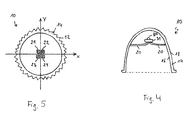
- Fig. 5 an embodiment is indicated in which the light source (as shown in FIG Fig. 3 ) is arranged on the bottom surface of the reflector 10, in the form of a plurality of, for example, four LEDs 21, 22, 23, 24. In the example shown, one LED 21, 22, 23, 24 associated with a quarter of the reflector 10.
- a coordinate system is used in the following, in which - as in Fig. 5 sketched - the x-axis and the y-axis perpendicular to the main axis S of the reflector 10 run.
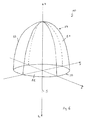
- Fig. 6 a perspective sketch of the main structure of the reflector 10 is shown.
- the reflector 10 may be a cup-shaped overall. It can be seen that with this definition for the reflector 10 a Light emission of the corresponding lamp is provided in a direction which is along the main axis S.
- the z-axis extends along the major axis S, the light output being directed in the negative z-direction; in Fig. 6 the direction of the light output is denoted by L.
- the reflector 10 in the direction of the light output L a reflector opening 50.
- the edge of the reflector opening 50 extends in the xy plane.
- eight octants I to VIII are formed by the coordinate system, with the reflector 10 being in the first four octants I to IV.
- the reflector 10 has a first reflector segment 51 and a second reflector segment 52, wherein the first reflector segment 51 is mechanically connected to the second reflector segment 52.
- the two reflector segments 51, 52 may represent parts of the reflector 10, which are formed by at least one section along a plane E, which extends through the main axis S of the reflector 10. It can be provided that the first reflector segment and the second reflector segment are formed such that they form a complete cup-shaped reflector in combination.
- the first reflector segment 51 is that part of the reflector 10 which lies in the first octant I
- the second reflector segment 52 that part of the reflector 10 which lies in the fourth octant IV.
- Fig. 7 is a longitudinal section through the first reflector segment 51 sketched schematically and in Fig. 8 a corresponding cross-section.
- the corresponding LED 22, which is assigned to the first reflector segment 51 It may in turn be arranged, for example, on a circuit board which is arranged directly on the "bottom surface” of the reflector segment 51.
- bottom surface is an end region of the reflector segment 51 located in the z-direction.
- the two reflector segments 51, 52 may have different optical properties.
- each of the two reflector segments 51, 52 may for example be part of a reflector which is rotationally symmetrical about the main axis S, hereinafter referred to as "R" for short.
- R rotationally symmetrical about the main axis S
- Fig. 9 the corresponding cross section is sketched.
- each of the two reflector segments 51, 52 may be a corresponding part of a so-called “wallwashers”; the corresponding cross section is in Fig. 10 sketched and labeled "WW”.
- each of the two reflector segments 51, 52 may be a corresponding part of a so-called "corner wallwashers"; the corresponding cross section is in Fig. 11 sketched and labeled "EW".
- the reflector segments 51, 52 may therefore differ, for example, in their shape - in particular in the form of their inner reflector walls - and as a result have different optical properties.
- the mechanical connection of the reflector segments 51, 52 may be non-positive and / or positive.
- the reflector segments 51, 52 may be connected to one another by means of plug connections. It can be provided that the reflector segments 51, 52 for this purpose at their adjacent boundaries - in Fig. 8 indicated - have flanges 60, where appropriate connecting means can attack.
- the mutually facing edges of the reflector segments 51, 52 are congruent.
- a total of four reflector segments 51, 52, 53, 54 are provided, wherein the third reflector segment 53 is that part of the reflector 10 which is in the third octant III, the fourth reflector segment 54 that part of the reflector 10, in the second octant II lies.
- the four reflector segments 51, 52, 53, 54 can thus be formed by two cuts, which run perpendicular to each other and each extend through the main axis S.
- the third and the fourth reflector segments 53, 54 may be constructed analogously to the first two reflector segments 51, 52.
- FIGS. 12, 13, 14 and 15 are outlined by corresponding cross-sections examples of reflectors, which are composed in different ways by the described reflector segments.
- Fig. 12 is a rotationally symmetrical reflector formed by four reflector segments "R”.
- Fig. 13 a reflector is formed, which is formed to one half of two reflector segments "R", the other half of two reflector segments "W”.
- Fig. 14 a reflector is formed, which is formed in three quarters of three reflector segments "R" and a quarter of a reflector segment "EW”.
- Fig. 15 a reflector is formed, which is formed into four quarters of four reflector segments "WW"; This results in a "double wallwasher”. So it is as it were a “reflector kit” formed, which makes it advantageous manufacturing technology to form with different reflector segments many different reflectors with different optical properties.
- each of the reflector segments each one or more LEDs is assigned or are - arranged for example on the bottom surface of the respective reflector segment.
- a luminaire can be formed with a light source and a reflector, in which the light source is arranged within a space circumscribed by the reflector.
- this luminaire can be a downlight.
Landscapes
- Engineering & Computer Science (AREA)
- General Engineering & Computer Science (AREA)
- Non-Portable Lighting Devices Or Systems Thereof (AREA)
Abstract
Description
- Die Erfindung betrifft einen Reflektor für eine Leuchte, sowie eine entsprechende Leuchte.
- Aus dem Stand der Technik sind derartige Leuchten beziehungsweise Reflektoren mit unterschiedlich gearteten Lichtverteilungseigenschaften bekannt. Beispielsweise gibt es Leuchten, die Licht rotationssymmetrisch verteilen oder Leuchten in Form von so genannten Wallwashern; mit einem Wallwasher wird eine unsymmetrische Lichtverteilung erzielt, die üblicherweise dazu dient, eine Wandfläche zu beleuchten. Zur Herstellung entsprechender Leuchten beziehungsweise Reflektoren ist es üblich, jeweils einen dementsprechenden Reflektortyp zu erzeugen.
- Der vorliegenden Erfindung liegt die Aufgabe zu Grunde, die Herstellung derartiger Leuchten beziehungsweise Reflektoren zu vereinfachen.
- Diese Aufgabe wird gemäß der Erfindung mit den in den unabhängigen Ansprüchen genannten Gegenständen gelöst. Besondere Ausführungsarten der Erfindung sind in den abhängigen Ansprüchen angegeben.
- Gemäß der Erfindung ist ein Reflektor für eine Leuchte vorgesehen; dabei weist der Reflektor ein erstes und ein zweites Reflektorsegment auf, die miteinander mechanisch verbunden sind.
- Auf diese Weise ist es möglich, mittels Herstellung lediglich zweier - hinsichtlich ihrer optischen Eigenschaften - unterschiedlicher Typen von Reflektorsegmenten Reflektoren beziehungsweise Leuchten von drei unterschiedlichen Typen zu bilden. Bezeichnet man mit "A" den ersten Reflektorsegmenttyp und mit "B" den zweiten Reflektorsegmenttyp, so ergibt eine Zusammensetzung von "A" mit "A", im Folgenden kurz mit "AA" bezeichnet, einen Reflektor eines ersten Typs, eine Zusammensetzung von "A" mit "B" beziehungsweise "AB" einen Reflektor eines zweiten Typs und eine Zusammensetzung von "B" mit "B" beziehungsweise "BB" einen Reflektor eines dritten Typs, wobei sich alle drei Reflektortypen in ihren optischen Eigenschaften voneinander unterscheiden. Im Gegensatz zum Stand der Technik ist es auf diese Weise möglich, mit nur zwei unterschiedlichen Reflektorbauteilen drei unterschiedliche Reflektoren beziehungsweise entsprechende Leuchten zu bilden. Die Herstellung ist dementsprechend vereinfacht.
- Vorteilhaft weist der Reflektor eine Hauptachse auf, wobei eine Lichtabgabe der Leuchte in einer Richtung längs der Hauptachse vorgesehen ist; das erste und das zweite Reflektorsegment stellen dabei Teile des Reflektors dar, die durch wenigstens einen durch die Hauptachse des Reflektors verlaufenden Schnitt gebildet sind.
- Vorteilhaft weisen das erste und das zweite Reflektorsegment unterschiedliche optische Eigenschaften auf.
- Vorteilhaft sind dabei die Reflektorsegmente kraftschlüssig und/oder formschlüssig, miteinander verbunden. Dies ist eine herstellungstechnisch besonders einfache und dabei geeignete Verbindungsart. Beispielsweise können die Reflektorsegmente mittels Steckverbindungen miteinander verbunden sein.
- Vorteilhaft weist der Reflektor weiterhin ein drittes Reflektorsegment und ein viertes Reflektorsegment auf, wobei die vier Reflektorsegmente Teile des Reflektors darstellen, die durch zwei senkrecht zueinander verlaufende Schnitte gebildet sind. Auf diese Weise lassen sich beispielsweise bei Verwendung lediglich zweier unterschiedlicher Typen von Reflektorsegmenten "A" und "B" sechs optisch unterschiedlich wirkende Reflektoren bilden, nämlich - unter Verwendung der obigen Bezeichnungsweise - die Typen "AAAA", "AAAB", "AABB", "ABBB", "BBBB" und "ABAB".
- Gemäß einem weiteren Aspekt der Erfindung ist eine Leuchte mit einer Lichtquelle und einem erfindungsgemäßen Reflektor vorgesehen, wobei die Lichtquelle innerhalb eines von dem Reflektor umschriebenen Raums angeordnet ist.
- Die Lichtquelle kann wenigstens eine LED umfassen. Dabei kann an jedem der Reflektorsegmente wenigstens eine LED angeordnet sein.
- Die wenigstens eine LED kann an einer Platine angeordnet sein, und die Platine unmittelbar an dem Reflektorsegment, beispielsweise an einer inneren Fläche einer Wand des Reflektorsegments.
- Vorteilhaft ist die Leuchte ein Downlight.
- Die Erfindung wird im Folgenden anhand eines Ausführungsbeispiels und mit Bezug auf die Zeichnungen näher erläutert. Es zeigen:
- Fig. 1
- einen schematischen Querschnitt durch eine erste Ausführungsform eines erfindungsgemäßen Reflektors,
- Fig. 2
- einen schematischen Querschnitt durch eine zweite Ausführungsform eines erfindungsgemäßen Reflektors,
- Fig. 3
- einen schematischen Längsschnitt durch einen erfindungsgemäßen Reflektor mit einer LED als Lichtquelle,
- Fig. 4
- einen schematischen Längsschnitt durch eine Variante eines erfindungsgemäßen Reflektors, bei der die Lichtquelle über eine Heatpipe mit dem Reflektor verbunden ist,
- Fig. 5
- eine Skizze zur möglichen Anordnung einer Lichtquelle,
- Fig. 6
- eine perspektivische Skizze der Hauptstruktur eines erfindungsgemäßen Reflektors,
- Fig. 7
- einen schematischen Längsschnitt durch ein erstes Reflektorsegment,
- Fig. 8
- einen entsprechenden Querschnitt,
- Figuren 9 bis 11
- Skizzen zu Beispielen von unterschiedlich geformten Reflektorsegmenten, und
- Figuren 12 bis 15
- Skizzen zu Reflektoren, die aus den gezeigten Reflektorsegmenten zusammengesetzt sind.
- In
Fig. 1 ist in sehr schematischer Form ein Querschnitt durch ein erstes Ausführungsbeispiel eines Reflektors 10 skizziert.Fig. 3 zeigt einen entsprechenden, ebenfalls sehr schematischen Längsschnitt. Der Reflektor 10 ist für eine (als solche nicht gezeigte) Leuchte mit einer Lichtquelle vorgesehen. Der Reflektor 10 dient zur Beeinflussung des Lichts, das von der Lichtquelle der Leuchte erzeugt wird. Die Lichtquelle kann, wie inFig. 3 angedeutet, beispielsweise wenigstens eine LED 2 umfassen. Die LED 2 kann dabei direkt auf einer Platine 3 angeordnet sein, die wiederum direkt an dem Reflektor 10, und zwar an dessen Bodenfläche, angeordnet ist. - Der Reflektor 10 weist Kühlrippen 12 auf, die dazu dienen, Wärme abzuführen, die von der Lichtquelle 2 bei Betrieb der Leuchte erzeugt wird. In dem in
Fig. 3 gezeigten Längsschnitt sind der Übersichtlichkeit halber die Kühlrippen nicht näher skizziert. - Die Kühlrippen 12 können in an sich bekannter Weise geformt sein. Die Kühlrippen 12 können insbesondere so groß gewählt sein, dass eine besonders effektive Wärmeabfuhr ermöglicht ist. Beispielsweise kann vorgesehen sein, dass die einzelnen Kühlrippen etwa mindestens so groß sind, dass sie eine Größenordnung kleiner sind, als der Reflektordurchmesser.
- Der Reflektor 10 kann eine Reflektorwand 14 umfassen, die - mit Bezug auf die für die Lichtquelle vorgesehene Lage - eine innere Fläche 16 und eine äußere Fläche 18 aufweist, wobei die Kühlrippen 12 an der inneren Fläche 16 und/oder an der äußeren Fläche 18 angeordnet sind. Bei dem in
Fig. 1 gezeigten Beispiel sind die Kühlrippen 12 an der inneren Fläche 16 angeordnet. -
Fig. 2 zeigt in einer derFig. 1 entsprechenden Darstellung ein zweites Ausführungsbeispiel, wobei die Bezugszeichen analog verwendet sind. Bei diesem Beispiel sind die Kühlrippen 12 an der äußeren Fläche 18 der Reflektorwand 14 angeordnet. - Es kann natürlich vorgesehen sein, dass die Kühlrippen 12 sowohl an der inneren Fläche 16, als auch an der äußeren Fläche 18 angeordnet sind. Dies ist grundsätzlich hinsichtlich einer besonders effektiven Wärmeabfuhr vorteilhaft.
- In den gezeigten Skizzen ist angedeutet, dass die Kühlrippen die gesamte innere Fläche 16 beziehungsweise die gesamte äußere Fläche 18 einnehmen. Es kann allerdings auch vorgesehen sein, dass die Kühlrippen 12 die entsprechende Fläche beziehungsweise die entsprechenden Flächen nur teilweise besetzen. Beispielsweise kann vorgesehen sein, dass die Kühlrippen 12 mindestens ein Viertel, vorzugsweise mindestens ein Drittel oder mindestens die Hälfte derjenigen Oberfläche des Reflektors 10 besetzen, die sich ohne die Kühlrippen 12 ergeben würde.
- Die innere Fläche 16 kann insbesondere eine reflektierende Fläche sein, die - in an sich bekannter Weise - dazu vorgesehen ist, Licht, das von der Lichtquelle stammt, in bestimmter Weise zu reflektieren, so dass eine gewünschte Abstrahlung erzielt werden kann. Wenn Kühlrippen 12 an dieser inneren, reflektierenden Fläche 16 vorgesehen sind, ist vorteilhaft sicherzustellen, dass die Art der Lichtabgabe nicht durch die Kühlrippen 12 in unerwünschter Wiese beeinträchtigt wird.
- Der erfindungsgemäße Reflektor 10 kann eine, in
Fig. 3 angedeutete Hauptachse S aufweisen. Insbesondere kann der Reflektor 10 einen - zur Hauptachse S senkrechten - Querschnitt aufweisen, der eine Kreisform festlegt. Dies ist an sich bei Reflektoren, die für Downlights verwendet werden, an sich so bekannt und üblich. - Bei dem Reflektor 10 können in diesem Fall die Kühlrippen 12 mit Bezug auf die Hauptachse S symmetrisch, insbesondere achsensymmetrisch oder rotationssymmetrisch ausgebildet sein.
- Bei einer entsprechenden Leuchte kann die Anordnung der Lichtquelle der in
Fig. 3 skizzierten Anordnung der Lichtquelle entsprechen, d. h. die Lichtquelle kann an der Bodenfläche des Reflektors 10 angeordnet sein. Vorteilhaft ist dabei die Lichtquelle thermisch möglichst unmittelbar mit dem Reflektor 10 verbunden, um einen möglichst effektiven Wärmeübergang von der Lichtquelle zu dem Reflektor 10 zu ermöglichen. - Die Lichtquelle kann, wie oben erwähnt, eine LED umfassen. In diesem Fall kann vorgesehen sein, dass die LED auf einer Platine angeordnet ist und die Platine unmittelbar an dem Reflektor 10 angeordnet ist.
- Bei der Leuchte kann es sich um ein Downlight handeln, bei dem eine oder mehrere LEDs als Lichtquelle vorgesehen sind; ein Reflektor für ein Downlight ist vergleichsweise groß, so dass eine vergleichsweise große Wärmeübergangsfläche gebildet ist. Außerdem ist der Reflektor im eingebauten Zustand der Leuchte üblicherweise nicht im isolierten Deckenhohlraum angeordnet, sondern steht mit der Umgebungsluft der zu beleuchtenden Anwendung in Kontakt.
- Wie in
Fig. 4 gezeigt, kann auch vorgesehen sein, dass die Lichtquelle über wenigstens eine Heatpipe 20 mit dem Reflektor 10 thermisch verbunden ist. In der Skizze derFig. 4 sind zwei Heatpipes 20 gezeigt. Bei der Lichtquelle kann es sich um wenigstens eine LED 30 handeln, die auf einer Platine 31 angeordnet ist, wobei die Platine 31 thermisch unmittelbar mit der wenigstens einen Heatpipe 20 verbunden ist. Die Heatpipe 20 kann auf der anderen Seite unmittelbar thermisch mit dem Reflektor 10, beispielsweise mit der inneren Reflektorwand 16, verbunden sein. Die Kühlrippen sind inFig. 4 der Übersichtlichkeit halber wiederum nicht skizziert; sie sind jedoch bei diesem Beispiel vorgesehen. - In
Fig. 5 ist eine Ausführungsform angedeutet, bei der die Lichtquelle (entsprechend der Darstellung ausFig. 3 ) an der Bodenfläche des Reflektors 10 angeordnet ist, und zwar in Form von mehreren, beispielsweise vier LEDs 21, 22, 23, 24. Im gezeigten Beispiel ist je eine LED 21, 22, 23, 24 einem Viertel des Reflektors 10 zugeordnet. - Zur leichteren Beschreibbarkeit wird im Folgenden ein Koordinatensystem verwendet, bei dem - wie in
Fig. 5 skizziert - die x-Achse und die y-Achse senkrecht zur Hauptachse S des Reflektors 10 verlaufen. InFig. 6 ist eine perspektivische Skizze der Hauptstruktur des Reflektors 10 dargestellt. Der Reflektor 10 kann insgesamt topfförmig sein. Man erkennt, dass mit dieser Festlegung für den Reflektor 10 eine Lichtabgabe der entsprechenden Leuchte in einer Richtung vorgesehen ist, die längs der Hauptachse S liegt. Bei dem gewählten Koordinatensystem verläuft die z-Achse längs der Hauptachse S, wobei die Lichtabgabe in die negative z-Richtung gerichtet ist; inFig. 6 ist die Richtung der Lichtabgabe mit L bezeichnet. Damit weist der Reflektor 10 in Richtung der Lichtabgabe L eine Reflektoröffnung 50 auf. Im gezeigten Beispiel verläuft der Rand der Reflektoröffnung 50 in der x-y-Ebene. Durch das Koordinatensystem sind somit acht Oktanten I bis VIII gebildet, wobei sich der Reflektor 10 in den ersten vier Oktanten I bis IV befindet. - Der erfindungsgemäße Reflektor 10 weist ein erstes Reflektorsegment 51 und ein zweites Reflektorsegment 52 auf, wobei das erste Reflektorsegment 51 mit dem zweiten Reflektorsegment 52 mechanisch verbunden ist. Die beiden Reflektorsegmente 51, 52 können Teile des Reflektors 10 darstellen, die durch wenigstens einen Schnitt längs einer Ebene E gebildet sind, die durch die Hauptachse S des Reflektors 10 verläuft. Es kann vorgesehen sein, dass das erste Reflektorsegment und das zweite Reflektorsegment derart ausgebildet sind, dass sie zusammengesetzt einen vollständigen topfförmigen Reflektor bilden. Im gezeigten Beispiel ist das erste Reflektorsegment 51 derjenige Teil des Reflektors 10, der im ersten Oktanten I liegt, das zweite Reflektorsegment 52 derjenige Teil des Reflektors 10, der im vierten Oktanten IV liegt.
- In
Fig. 7 ist ein Längsschnitt durch das erste Reflektorsegment 51 schematisch skizziert und inFig. 8 ein entsprechender Querschnitt. Man erkennt die entsprechende LED 22, die dem ersten Reflektorsegment 51 zugeordnet ist. Sie kann wiederum beispielsweise auf einer Platine angeordnet sein, die direkt an der "Bodenfläche" des Reflektorsegments 51 angeordnet ist. Mit "Bodenfläche" sei dabei ein in z-Richtung gelegener Endbereich des Reflektorsegments 51 bezeichnet. - Die beiden Reflektorsegmente 51, 52 können unterschiedliche optische Eigenschaften aufweisen. Dabei kann jedes der beiden Reflektorsegmente 51, 52 beispielsweise Teil eines um die Hauptachse S rotationssymmetrischen Reflektors sein, im Folgenden kurz mit "R" bezeichnet. In
Fig. 9 ist der entsprechende Querschnitt skizziert. Weiterhin beispielsweise kann jedes der beiden Reflektorsegmente 51, 52 ein entsprechendes Teil eines so genannten "Wallwashers" sein; der entsprechende Querschnitt ist inFig. 10 skizziert und mit "WW" bezeichnet. Weiterhin beispielsweise kann jedes der beiden Reflektorsegmente 51, 52 ein entsprechendes Teil eines so genannten "Eck-Wallwashers" sein; der entsprechende Querschnitt ist inFig. 11 skizziert und mit "EW" bezeichnet. - Die Reflektorsegmente 51, 52 können sich also beispielsweise in ihrer Form unterscheiden - insbesondere in der Form ihrer inneren Reflektorwände - und dadurch bedingt unterschiedliche optische Eigenschaften aufweisen.
- Die mechanische Verbindung der Reflektorsegmente 51, 52 kann kraftschlüssig und/oder formschlüssig sein. Beispielsweise können die Reflektorsegmente 51, 52 mittels Steckverbindungen miteinander verbunden sein. Es kann vorgesehen sein, dass die Reflektorsegmente 51, 52 hierfür an ihren benachbarten Begrenzungen - in
Fig. 8 angedeutete - Flansche 60 aufweisen, an denen entsprechende Verbindungsmittel angreifen können. Vorzugsweise sind die zueinander weisenden Ränder der Reflektorsegmente 51, 52 deckungsgleich. - Es kann vorgesehen sein, dass mehr als zwei Reflektorsegmente vorgesehen sind, die zusammengesetzt einen topfförmigen Reflektor bilden. In dem Beispiel, das in
Fig. 6 skizzenhaft gezeigt ist, sind insgesamt vier Reflektorsegmente 51, 52, 53, 54 vorgesehen, wobei das dritte Reflektorsegment 53 derjenige Teil des Reflektors 10 ist, der im dritten Oktanten III liegt, das vierte Reflektorsegment 54 derjenige Teil des Reflektors 10, der im zweiten Oktanten II liegt. Die vier Reflektorsegmente 51, 52, 53, 54 können also durch zwei Schnitte gebildet sein, die senkrecht zueinander verlaufen und jeweils durch die Hauptachse S verlaufen. Das dritte und das vierte Reflektorsegment 53, 54 können analog zu den ersten beiden Reflektorsegmenten 51, 52 aufgebaut sein. - In den
Figuren 12, 13, 14 und 15 sind anhand von entsprechenden Querschnitten Beispiele für Reflektoren skizziert, die in unterschiedlicher Weise durch die beschriebenen Reflektorsegmente zusammengesetzt sind. GemäßFig. 12 ist ein rotationssymmetrischer Reflektor durch vier Reflektorsegmente "R" gebildet. GemäßFig. 13 ist ein Reflektor gebildet, der zur einen Hälfte aus zwei Reflektorsegmenten "R" gebildet ist, zur anderen Hälfte aus zwei Reflektorsegmenten "W". GemäßFig. 14 ist ein Reflektor gebildet, der zu drei Vierteln aus drei Reflektorsegmenten "R" gebildet ist und zu einem Viertel aus einem Reflektorsegment "EW". GemäßFig. 15 ist ein Reflektor gebildet, der zu vier Vierteln aus vier Reflektorsegmenten "WW" gebildet ist; hierdurch ergibt sich ein "Doppel-Wallwasher". Es ist also so zusagen ein "Reflektorbaukasten" gebildet, der es herstellungstechnisch vorteilhaft ermöglicht, mit unterschiedlichen Reflektorsegmenten viele unterschiedliche Reflektoren mit unterschiedlichen optischen Eigenschaften zu bilden. - Als Lichtquelle kann vorgesehen sein, dass - wie oben dargestellt - jedem der Reflektorsegmente jeweils eine oder auch mehrere LEDs zugeordnet ist beziehungsweise sind - beispielsweise an der Bodenfläche des betreffenden Reflektorsegments angeordnet. Auf diese Weise kann eine Leuchte mit einer Lichtquelle und einem Reflektor gebildet sein, bei der die Lichtquelle innerhalb eines von dem Reflektor umschriebenen Raums angeordnet ist.
- Bei dieser Leuchte kann es sich beispielsweise um ein Downlight handeln.
Claims (11)
- Reflektor für eine Leuchte,
dadurch gekennzeichnet,
dass der Reflektor (10) ein erstes und ein zweites Reflektorsegment (51, 52) aufweist, wobei das erste und das zweite Reflektorsegment (51, 52) mechanisch miteinander verbunden sind. - Reflektor nach Anspruch 1,
aufweisend eine Hauptachse (S), wobei eine Lichtabgabe der Leuchte in einer Richtung (L) längs der Hauptachse (S) vorgesehen ist,
wobei das erste und das zweite Reflektorsegment (51, 52) Teile des Reflektors (10) darstellen, die durch wenigstens einen durch die Hauptachse (S) des Reflektors (10) verlaufenden Schnitt gebildet sind. - Reflektor nach Anspruch 1 oder 2,
wobei das erste Reflektorsegment (51) und das zweite Reflektorsegment (52) unterschiedliche optische Eigenschaften aufweisen. - Reflektor nach einem der vorhergehenden Ansprüche,
bei dem die Reflektorsegmente (51, 52) kraftschlüssig und/oder formschlüssig, miteinander verbunden sind. - Reflektor nach Anspruch 4,
bei dem die Reflektorsegmente (51, 52) mittels Steckverbindungen miteinander verbunden sind. - Reflektor nach einem der vorhergehenden Ansprüche,
weiterhin aufweisend ein drittes Reflektorsegment (53) und ein viertes Reflektorsegment (54), wobei die vier Reflektorsegmente (51, 52, 53, 54) Teile des Reflektors (10) darstellen, die durch zwei senkrecht zueinander verlaufende Schnitte gebildet sind. - Leuchte mit einer Lichtquelle und einem Reflektor nach einem der vorhergehenden Ansprüche, wobei die Lichtquelle (2, 21, 22, 23, 24, 30) innerhalb eines von dem Reflektor (10) umschriebenen Raums angeordnet ist.
- Leuchte nach Anspruch 7,
bei der die Lichtquelle wenigstens eine LED (2, 21, 22, 23, 24, 30) umfasst. - Leuchte nach Anspruch 7 oder 8,
bei der an jedem Reflektorsegment (51, 52, 53, 54) wenigstens eine LED (21, 22, 23, 24) angeordnet ist. - Leuchte nach Anspruch 8 oder 9,
bei der die wenigstens eine LED (21, 22, 23, 24) an einer Platine angeordnet ist und die Platine unmittelbar an einer Innenseite des Reflektors. - Leuchte nach einem der Ansprüche 7 bis 10
in Form eines Downlights.
Applications Claiming Priority (1)
| Application Number | Priority Date | Filing Date | Title |
|---|---|---|---|
| DE102009007490A DE102009007490A1 (de) | 2009-02-05 | 2009-02-05 | Reflektorbaukastensystem |
Publications (2)
| Publication Number | Publication Date |
|---|---|
| EP2216588A1 true EP2216588A1 (de) | 2010-08-11 |
| EP2216588B1 EP2216588B1 (de) | 2014-07-30 |
Family
ID=42103860
Family Applications (1)
| Application Number | Title | Priority Date | Filing Date |
|---|---|---|---|
| EP10152754.7A Not-in-force EP2216588B1 (de) | 2009-02-05 | 2010-02-05 | Reflektorbaukastensystem |
Country Status (2)
| Country | Link |
|---|---|
| EP (1) | EP2216588B1 (de) |
| DE (1) | DE102009007490A1 (de) |
Cited By (2)
| Publication number | Priority date | Publication date | Assignee | Title |
|---|---|---|---|---|
| WO2014019703A1 (de) * | 2012-08-03 | 2014-02-06 | Bartenbach Holding Gmbh | Beleuchtungsvorrichtung |
| US11258283B2 (en) | 2013-10-31 | 2022-02-22 | Resmed Paris Sas | Apparatus for treating a respiratory disorder with a power source connection |
Citations (6)
| Publication number | Priority date | Publication date | Assignee | Title |
|---|---|---|---|---|
| US6382803B1 (en) * | 2000-05-02 | 2002-05-07 | Nsi Enterprises, Inc. | Faceted reflector assembly |
| US20050088758A1 (en) * | 2003-02-04 | 2005-04-28 | Light Prescriptions Innovators, Llc, A Delaware Limited Liability Company | Etendue-squeezing illumination optics |
| DE102004046389A1 (de) * | 2004-09-24 | 2006-04-06 | Bruggaier, Christoph F. | Scheinwerfer und Verfahren zu seiner Herstellung |
| US20060181873A1 (en) * | 2005-02-17 | 2006-08-17 | Underwater Kinetics, Inc. | Lighting system and method and reflector for use in same |
| US20070268707A1 (en) * | 2006-05-22 | 2007-11-22 | Edison Price Lighting, Inc. | LED array wafer lighting fixture |
| EP2019253A2 (de) * | 2007-07-26 | 2009-01-28 | ERCO GmbH | Leuchte zur Ausleuchtung einer Gebäudefläche |
Family Cites Families (2)
| Publication number | Priority date | Publication date | Assignee | Title |
|---|---|---|---|---|
| US7237927B2 (en) * | 2004-06-17 | 2007-07-03 | Osram Sylvania Inc. | Light emitting diode lamp with conically focused light guides |
| DE202005018591U1 (de) * | 2005-11-28 | 2006-03-09 | Siteco Beleuchtungstechnik Gmbh | Downlight mit zwei Lampen |
-
2009
- 2009-02-05 DE DE102009007490A patent/DE102009007490A1/de not_active Withdrawn
-
2010
- 2010-02-05 EP EP10152754.7A patent/EP2216588B1/de not_active Not-in-force
Patent Citations (6)
| Publication number | Priority date | Publication date | Assignee | Title |
|---|---|---|---|---|
| US6382803B1 (en) * | 2000-05-02 | 2002-05-07 | Nsi Enterprises, Inc. | Faceted reflector assembly |
| US20050088758A1 (en) * | 2003-02-04 | 2005-04-28 | Light Prescriptions Innovators, Llc, A Delaware Limited Liability Company | Etendue-squeezing illumination optics |
| DE102004046389A1 (de) * | 2004-09-24 | 2006-04-06 | Bruggaier, Christoph F. | Scheinwerfer und Verfahren zu seiner Herstellung |
| US20060181873A1 (en) * | 2005-02-17 | 2006-08-17 | Underwater Kinetics, Inc. | Lighting system and method and reflector for use in same |
| US20070268707A1 (en) * | 2006-05-22 | 2007-11-22 | Edison Price Lighting, Inc. | LED array wafer lighting fixture |
| EP2019253A2 (de) * | 2007-07-26 | 2009-01-28 | ERCO GmbH | Leuchte zur Ausleuchtung einer Gebäudefläche |
Cited By (3)
| Publication number | Priority date | Publication date | Assignee | Title |
|---|---|---|---|---|
| WO2014019703A1 (de) * | 2012-08-03 | 2014-02-06 | Bartenbach Holding Gmbh | Beleuchtungsvorrichtung |
| EP3199869A1 (de) | 2012-08-03 | 2017-08-02 | Bartenbach Holding GmbH | Beleuchtungsvorrichtung |
| US11258283B2 (en) | 2013-10-31 | 2022-02-22 | Resmed Paris Sas | Apparatus for treating a respiratory disorder with a power source connection |
Also Published As
| Publication number | Publication date |
|---|---|
| EP2216588B1 (de) | 2014-07-30 |
| DE102009007490A1 (de) | 2010-08-12 |
Similar Documents
| Publication | Publication Date | Title |
|---|---|---|
| DE102007037822A1 (de) | Beleuchtungsvorrichtung | |
| WO2006076899A2 (de) | Beleuchtungseinrichtung | |
| EP2204604A1 (de) | Leuchte | |
| DE102009047558A1 (de) | Zweiteiliger LED-Streifen-Steckverbinder für Oberflächenmontage und LED-Baugruppe | |
| DE202008017116U1 (de) | Glühbirnenanordnung | |
| DE102017116885B4 (de) | Leuchtmittel und Linse für ein Leuchtmittel | |
| EP3473918B1 (de) | Beleuchtungsvorrichtung für einen kraftfahrzeugscheinwerfer | |
| EP2360427A2 (de) | Drei-Zonen Reflektor | |
| DE202013011143U1 (de) | LED-Einheit mit Linse | |
| EP2986894B1 (de) | Leiterplatte für eine leuchte | |
| DE202013010052U1 (de) | Anordnung zur Lichtabgabe sowie Leuchte mit einer solchen Anordnung | |
| DE202011052295U1 (de) | LED-Leuchte insbesondere für Schienenfahrzeuge, insbesondere LED-Leuchte zur Verwendung als Signalleuchte und/oder Scheinwerfer, sowie optisches Bauelement für LED-Signalleuchten und LED-Scheinwerfer | |
| EP2216588B1 (de) | Reflektorbaukastensystem | |
| EP2439445A2 (de) | LED-Leuchte mit gebogenem Lichtabgabebereich | |
| WO2016096608A1 (de) | Led-träger mit einer led und leuchte mit einem derartigen led-träger | |
| DE102008006229B4 (de) | Straßenbeleuchtungseinrichtung | |
| EP2365243B1 (de) | Leuchte | |
| EP3582263A1 (de) | Lichterzeugende baugruppe für einen scheinwerfer sowie scheinwerfer | |
| EP2989378B1 (de) | Led-leuchte mit unterschiedlich einstellbaren lichtverteilungen | |
| DE102011012132B3 (de) | Unterwasserscheinwerfer | |
| EP2734777B2 (de) | Anordnung zur lichtabgabe | |
| DE202010008431U1 (de) | Flexible Beleuchtungsanordnung | |
| DE202022101995U1 (de) | Lichtleitelement für Rettungszeichenleuchte | |
| DE102010001628A1 (de) | Reflektor als Kühlkörper | |
| EP2796779A1 (de) | Leuchte mit optischem System zur Lichtabgabe über eine längliche Lichtaustrittsöffnung |
Legal Events
| Date | Code | Title | Description |
|---|---|---|---|
| PUAI | Public reference made under article 153(3) epc to a published international application that has entered the european phase |
Free format text: ORIGINAL CODE: 0009012 |
|
| AK | Designated contracting states |
Kind code of ref document: A1 Designated state(s): AT BE BG CH CY CZ DE DK EE ES FI FR GB GR HR HU IE IS IT LI LT LU LV MC MK MT NL NO PL PT RO SE SI SK SM TR |
|
| AX | Request for extension of the european patent |
Extension state: AL BA RS |
|
| 17P | Request for examination filed |
Effective date: 20110211 |
|
| 17Q | First examination report despatched |
Effective date: 20121114 |
|
| RIC1 | Information provided on ipc code assigned before grant |
Ipc: F21Y 101/02 20060101ALN20131216BHEP Ipc: F21V 7/09 20060101ALI20131216BHEP Ipc: F21V 7/10 20060101ALI20131216BHEP Ipc: F21V 7/04 20060101ALI20131216BHEP Ipc: F21S 8/02 20060101AFI20131216BHEP |
|
| GRAP | Despatch of communication of intention to grant a patent |
Free format text: ORIGINAL CODE: EPIDOSNIGR1 |
|
| INTG | Intention to grant announced |
Effective date: 20140220 |
|
| RIN1 | Information on inventor provided before grant (corrected) |
Inventor name: VAMBERSZKY, KLAUS |
|
| GRAS | Grant fee paid |
Free format text: ORIGINAL CODE: EPIDOSNIGR3 |
|
| GRAA | (expected) grant |
Free format text: ORIGINAL CODE: 0009210 |
|
| AK | Designated contracting states |
Kind code of ref document: B1 Designated state(s): AT BE BG CH CY CZ DE DK EE ES FI FR GB GR HR HU IE IS IT LI LT LU LV MC MK MT NL NO PL PT RO SE SI SK SM TR |
|
| REG | Reference to a national code |
Ref country code: GB Ref legal event code: FG4D Free format text: NOT ENGLISH |
|
| REG | Reference to a national code |
Ref country code: CH Ref legal event code: NV Representative=s name: FIAMMENGHI-FIAMMENGHI, CH Ref country code: CH Ref legal event code: EP |
|
| REG | Reference to a national code |
Ref country code: AT Ref legal event code: REF Ref document number: 680163 Country of ref document: AT Kind code of ref document: T Effective date: 20140815 |
|
| REG | Reference to a national code |
Ref country code: IE Ref legal event code: FG4D Free format text: LANGUAGE OF EP DOCUMENT: GERMAN |
|
| REG | Reference to a national code |
Ref country code: DE Ref legal event code: R096 Ref document number: 502010007545 Country of ref document: DE Effective date: 20140911 |
|
| REG | Reference to a national code |
Ref country code: NL Ref legal event code: VDEP Effective date: 20140730 |
|
| REG | Reference to a national code |
Ref country code: LT Ref legal event code: MG4D |
|
| PG25 | Lapsed in a contracting state [announced via postgrant information from national office to epo] |
Ref country code: BG Free format text: LAPSE BECAUSE OF FAILURE TO SUBMIT A TRANSLATION OF THE DESCRIPTION OR TO PAY THE FEE WITHIN THE PRESCRIBED TIME-LIMIT Effective date: 20141030 Ref country code: LT Free format text: LAPSE BECAUSE OF FAILURE TO SUBMIT A TRANSLATION OF THE DESCRIPTION OR TO PAY THE FEE WITHIN THE PRESCRIBED TIME-LIMIT Effective date: 20140730 Ref country code: NO Free format text: LAPSE BECAUSE OF FAILURE TO SUBMIT A TRANSLATION OF THE DESCRIPTION OR TO PAY THE FEE WITHIN THE PRESCRIBED TIME-LIMIT Effective date: 20141030 Ref country code: GR Free format text: LAPSE BECAUSE OF FAILURE TO SUBMIT A TRANSLATION OF THE DESCRIPTION OR TO PAY THE FEE WITHIN THE PRESCRIBED TIME-LIMIT Effective date: 20141031 Ref country code: SE Free format text: LAPSE BECAUSE OF FAILURE TO SUBMIT A TRANSLATION OF THE DESCRIPTION OR TO PAY THE FEE WITHIN THE PRESCRIBED TIME-LIMIT Effective date: 20140730 Ref country code: FI Free format text: LAPSE BECAUSE OF FAILURE TO SUBMIT A TRANSLATION OF THE DESCRIPTION OR TO PAY THE FEE WITHIN THE PRESCRIBED TIME-LIMIT Effective date: 20140730 Ref country code: PT Free format text: LAPSE BECAUSE OF FAILURE TO SUBMIT A TRANSLATION OF THE DESCRIPTION OR TO PAY THE FEE WITHIN THE PRESCRIBED TIME-LIMIT Effective date: 20141202 Ref country code: ES Free format text: LAPSE BECAUSE OF FAILURE TO SUBMIT A TRANSLATION OF THE DESCRIPTION OR TO PAY THE FEE WITHIN THE PRESCRIBED TIME-LIMIT Effective date: 20140730 |
|
| PG25 | Lapsed in a contracting state [announced via postgrant information from national office to epo] |
Ref country code: HR Free format text: LAPSE BECAUSE OF FAILURE TO SUBMIT A TRANSLATION OF THE DESCRIPTION OR TO PAY THE FEE WITHIN THE PRESCRIBED TIME-LIMIT Effective date: 20140730 Ref country code: NL Free format text: LAPSE BECAUSE OF FAILURE TO SUBMIT A TRANSLATION OF THE DESCRIPTION OR TO PAY THE FEE WITHIN THE PRESCRIBED TIME-LIMIT Effective date: 20140730 Ref country code: LV Free format text: LAPSE BECAUSE OF FAILURE TO SUBMIT A TRANSLATION OF THE DESCRIPTION OR TO PAY THE FEE WITHIN THE PRESCRIBED TIME-LIMIT Effective date: 20140730 Ref country code: IS Free format text: LAPSE BECAUSE OF FAILURE TO SUBMIT A TRANSLATION OF THE DESCRIPTION OR TO PAY THE FEE WITHIN THE PRESCRIBED TIME-LIMIT Effective date: 20141130 Ref country code: PL Free format text: LAPSE BECAUSE OF FAILURE TO SUBMIT A TRANSLATION OF THE DESCRIPTION OR TO PAY THE FEE WITHIN THE PRESCRIBED TIME-LIMIT Effective date: 20140730 Ref country code: CY Free format text: LAPSE BECAUSE OF FAILURE TO SUBMIT A TRANSLATION OF THE DESCRIPTION OR TO PAY THE FEE WITHIN THE PRESCRIBED TIME-LIMIT Effective date: 20140730 |
|
| PG25 | Lapsed in a contracting state [announced via postgrant information from national office to epo] |
Ref country code: EE Free format text: LAPSE BECAUSE OF FAILURE TO SUBMIT A TRANSLATION OF THE DESCRIPTION OR TO PAY THE FEE WITHIN THE PRESCRIBED TIME-LIMIT Effective date: 20140730 Ref country code: CZ Free format text: LAPSE BECAUSE OF FAILURE TO SUBMIT A TRANSLATION OF THE DESCRIPTION OR TO PAY THE FEE WITHIN THE PRESCRIBED TIME-LIMIT Effective date: 20140730 Ref country code: DK Free format text: LAPSE BECAUSE OF FAILURE TO SUBMIT A TRANSLATION OF THE DESCRIPTION OR TO PAY THE FEE WITHIN THE PRESCRIBED TIME-LIMIT Effective date: 20140730 Ref country code: IT Free format text: LAPSE BECAUSE OF FAILURE TO SUBMIT A TRANSLATION OF THE DESCRIPTION OR TO PAY THE FEE WITHIN THE PRESCRIBED TIME-LIMIT Effective date: 20140730 Ref country code: SK Free format text: LAPSE BECAUSE OF FAILURE TO SUBMIT A TRANSLATION OF THE DESCRIPTION OR TO PAY THE FEE WITHIN THE PRESCRIBED TIME-LIMIT Effective date: 20140730 Ref country code: RO Free format text: LAPSE BECAUSE OF FAILURE TO SUBMIT A TRANSLATION OF THE DESCRIPTION OR TO PAY THE FEE WITHIN THE PRESCRIBED TIME-LIMIT Effective date: 20140730 |
|
| REG | Reference to a national code |
Ref country code: DE Ref legal event code: R097 Ref document number: 502010007545 Country of ref document: DE |
|
| PLBE | No opposition filed within time limit |
Free format text: ORIGINAL CODE: 0009261 |
|
| STAA | Information on the status of an ep patent application or granted ep patent |
Free format text: STATUS: NO OPPOSITION FILED WITHIN TIME LIMIT |
|
| PG25 | Lapsed in a contracting state [announced via postgrant information from national office to epo] |
Ref country code: BE Free format text: LAPSE BECAUSE OF NON-PAYMENT OF DUE FEES Effective date: 20150228 |
|
| 26N | No opposition filed |
Effective date: 20150504 |
|
| PG25 | Lapsed in a contracting state [announced via postgrant information from national office to epo] |
Ref country code: LU Free format text: LAPSE BECAUSE OF FAILURE TO SUBMIT A TRANSLATION OF THE DESCRIPTION OR TO PAY THE FEE WITHIN THE PRESCRIBED TIME-LIMIT Effective date: 20150205 |
|
| PG25 | Lapsed in a contracting state [announced via postgrant information from national office to epo] |
Ref country code: MC Free format text: LAPSE BECAUSE OF FAILURE TO SUBMIT A TRANSLATION OF THE DESCRIPTION OR TO PAY THE FEE WITHIN THE PRESCRIBED TIME-LIMIT Effective date: 20140730 |
|
| REG | Reference to a national code |
Ref country code: IE Ref legal event code: MM4A |
|
| PG25 | Lapsed in a contracting state [announced via postgrant information from national office to epo] |
Ref country code: SI Free format text: LAPSE BECAUSE OF FAILURE TO SUBMIT A TRANSLATION OF THE DESCRIPTION OR TO PAY THE FEE WITHIN THE PRESCRIBED TIME-LIMIT Effective date: 20140730 |
|
| PG25 | Lapsed in a contracting state [announced via postgrant information from national office to epo] |
Ref country code: IE Free format text: LAPSE BECAUSE OF NON-PAYMENT OF DUE FEES Effective date: 20150205 |
|
| REG | Reference to a national code |
Ref country code: FR Ref legal event code: PLFP Year of fee payment: 7 |
|
| PGFP | Annual fee paid to national office [announced via postgrant information from national office to epo] |
Ref country code: CH Payment date: 20160225 Year of fee payment: 7 |
|
| PGFP | Annual fee paid to national office [announced via postgrant information from national office to epo] |
Ref country code: AT Payment date: 20160225 Year of fee payment: 7 |
|
| PG25 | Lapsed in a contracting state [announced via postgrant information from national office to epo] |
Ref country code: MT Free format text: LAPSE BECAUSE OF FAILURE TO SUBMIT A TRANSLATION OF THE DESCRIPTION OR TO PAY THE FEE WITHIN THE PRESCRIBED TIME-LIMIT Effective date: 20140730 |
|
| REG | Reference to a national code |
Ref country code: FR Ref legal event code: PLFP Year of fee payment: 8 |
|
| PG25 | Lapsed in a contracting state [announced via postgrant information from national office to epo] |
Ref country code: HU Free format text: LAPSE BECAUSE OF FAILURE TO SUBMIT A TRANSLATION OF THE DESCRIPTION OR TO PAY THE FEE WITHIN THE PRESCRIBED TIME-LIMIT; INVALID AB INITIO Effective date: 20100205 Ref country code: SM Free format text: LAPSE BECAUSE OF FAILURE TO SUBMIT A TRANSLATION OF THE DESCRIPTION OR TO PAY THE FEE WITHIN THE PRESCRIBED TIME-LIMIT Effective date: 20140730 |
|
| PG25 | Lapsed in a contracting state [announced via postgrant information from national office to epo] |
Ref country code: TR Free format text: LAPSE BECAUSE OF FAILURE TO SUBMIT A TRANSLATION OF THE DESCRIPTION OR TO PAY THE FEE WITHIN THE PRESCRIBED TIME-LIMIT Effective date: 20140730 |
|
| REG | Reference to a national code |
Ref country code: CH Ref legal event code: PL |
|
| REG | Reference to a national code |
Ref country code: AT Ref legal event code: MM01 Ref document number: 680163 Country of ref document: AT Kind code of ref document: T Effective date: 20170205 |
|
| PG25 | Lapsed in a contracting state [announced via postgrant information from national office to epo] |
Ref country code: AT Free format text: LAPSE BECAUSE OF NON-PAYMENT OF DUE FEES Effective date: 20170205 Ref country code: CH Free format text: LAPSE BECAUSE OF NON-PAYMENT OF DUE FEES Effective date: 20170228 Ref country code: LI Free format text: LAPSE BECAUSE OF NON-PAYMENT OF DUE FEES Effective date: 20170228 |
|
| REG | Reference to a national code |
Ref country code: FR Ref legal event code: PLFP Year of fee payment: 9 |
|
| PG25 | Lapsed in a contracting state [announced via postgrant information from national office to epo] |
Ref country code: MK Free format text: LAPSE BECAUSE OF FAILURE TO SUBMIT A TRANSLATION OF THE DESCRIPTION OR TO PAY THE FEE WITHIN THE PRESCRIBED TIME-LIMIT Effective date: 20140730 |
|
| REG | Reference to a national code |
Ref country code: DE Ref legal event code: R084 Ref document number: 502010007545 Country of ref document: DE |
|
| RIC2 | Information provided on ipc code assigned after grant |
Ipc: F21Y 101/02 20000101ALN20131216BHEP Ipc: F21S 8/02 20060101AFI20131216BHEP Ipc: F21V 7/10 20060101ALI20131216BHEP Ipc: F21V 7/09 20060101ALI20131216BHEP Ipc: F21V 7/04 20060101ALI20131216BHEP |
|
| PGFP | Annual fee paid to national office [announced via postgrant information from national office to epo] |
Ref country code: GB Payment date: 20220222 Year of fee payment: 13 |
|
| PGFP | Annual fee paid to national office [announced via postgrant information from national office to epo] |
Ref country code: FR Payment date: 20220224 Year of fee payment: 13 |
|
| PGFP | Annual fee paid to national office [announced via postgrant information from national office to epo] |
Ref country code: DE Payment date: 20230227 Year of fee payment: 14 |
|
| P01 | Opt-out of the competence of the unified patent court (upc) registered |
Effective date: 20230530 |
|
| GBPC | Gb: european patent ceased through non-payment of renewal fee |
Effective date: 20230205 |
|
| PG25 | Lapsed in a contracting state [announced via postgrant information from national office to epo] |
Ref country code: GB Free format text: LAPSE BECAUSE OF NON-PAYMENT OF DUE FEES Effective date: 20230205 |
|
| PG25 | Lapsed in a contracting state [announced via postgrant information from national office to epo] |
Ref country code: GB Free format text: LAPSE BECAUSE OF NON-PAYMENT OF DUE FEES Effective date: 20230205 Ref country code: FR Free format text: LAPSE BECAUSE OF NON-PAYMENT OF DUE FEES Effective date: 20230228 |
|
| REG | Reference to a national code |
Ref country code: DE Ref legal event code: R119 Ref document number: 502010007545 Country of ref document: DE |
|
| PG25 | Lapsed in a contracting state [announced via postgrant information from national office to epo] |
Ref country code: DE Free format text: LAPSE BECAUSE OF NON-PAYMENT OF DUE FEES Effective date: 20240903 |
|
| PG25 | Lapsed in a contracting state [announced via postgrant information from national office to epo] |
Ref country code: DE Free format text: LAPSE BECAUSE OF NON-PAYMENT OF DUE FEES Effective date: 20240903 |