EP2218835A1 - Shovel loader comprising two hinged frames. - Google Patents
Shovel loader comprising two hinged frames. Download PDFInfo
- Publication number
- EP2218835A1 EP2218835A1 EP10447007A EP10447007A EP2218835A1 EP 2218835 A1 EP2218835 A1 EP 2218835A1 EP 10447007 A EP10447007 A EP 10447007A EP 10447007 A EP10447007 A EP 10447007A EP 2218835 A1 EP2218835 A1 EP 2218835A1
- Authority
- EP
- European Patent Office
- Prior art keywords
- frame
- hinge pin
- relation
- liquid
- reservoirs
- Prior art date
- Legal status (The legal status is an assumption and is not a legal conclusion. Google has not performed a legal analysis and makes no representation as to the accuracy of the status listed.)
- Granted
Links
Images



Classifications
-
- E—FIXED CONSTRUCTIONS
- E02—HYDRAULIC ENGINEERING; FOUNDATIONS; SOIL SHIFTING
- E02F—DREDGING; SOIL-SHIFTING
- E02F9/00—Component parts of dredgers or soil-shifting machines, not restricted to one of the kinds covered by groups E02F3/00 - E02F7/00
- E02F9/08—Superstructures; Supports for superstructures
- E02F9/0841—Articulated frame, i.e. having at least one pivot point between two travelling gear units
Definitions
- the invention concerns a vehicle, in particular a shovel loader, comprising a first frame with a first set of wheels and a second frame with a second set of wheels, whereby the first frame is connected to the second frame by means of a hinged joint, such that the first frame can move in relation to the second frame, whereby means are provided to dampen the movement of the first frame in relation to the second frame.
- Such vehicles are thus provided with a buckling control, whereby a first frame, which for example forms the front part of the vehicle, is hinge-mounted and/or mounted in a pivoting manner to a second frame which then forms the rear part of the vehicle.
- These vehicles usually comprise four wheels whereby the front and the rear part of the vehicle are each carried by wheels.
- Said rear part usually has a large mass so as to keep the vehicle stable, and it is usually provided with a seat for the driver.
- said vehicles are usually provided with a lifting arm on which can be mounted detachable elements such as for example a loading shovel.
- a lifting arm on which can be mounted detachable elements such as for example a loading shovel.
- These vehicles are particularly advantageous in that they are very manoeuvrable and compact, but it turns out that they are very unstable and that, when used on rough ground, a lot of accidents happen due to the vehicle tipping when riding over a bump or along a slope at reasonable speed. The latter is all the more so when the loading bucket of the vehicle is loaded with earth, for example, and the lifting arm is directed upward.
- Document FR 2 663 590 describes a vehicle comprising two frames which are connected by means of a hinged joint.
- the hinged joint which is applied in said vehicle, the risk of the vehicle tipping is practically negligible.
- Said document FR 2 663 590 describes a system which makes it possible to dampen oscillations of both frames in relation to one another on the one hand, and to stabilize both frames in relation to one another when the vehicle is being worked with on the other hand.
- no solution is offered to stabilize a vehicle moving with a load in the loading bucket over rough ground.
- the invention aims to remedy the above-mentioned disadvantages and to provide a vehicle with buckling control which proves to be extremely stable, even when moving at high speed with a loaded loading bucket over rough ground.
- said means to dampen the movement of the first frame in relation to the second frame comprise two liquid reservoirs containing a hydraulic liquid which are connected via a throttle valve whereby, during the movement of said first frame in relation to the second frame, said liquid is displaced between both reservoirs via said throttle valve.
- said hinged joint has a hinge pin around which the first frame can rotate in relation to the second frame, whereby this hinge pin can also pivot and said liquid reservoirs co-operate with the hinged joint such that, when the hinge pin moves in a direction crosswise to the longitudinal axis of the second frame, liquid will be displaced between both reservoirs via said throttle valve.
- said hinged joint has a hinge pin which is determined by a point of rotation on the one hand around which the hinge pin can pivot, and which has a fixed position in relation to both frames, and a hinge point situated almost vertically above said point of rotation on the other hand which is fixed in relation to the first frame and hinge-mounted to the first far end of a rod, whereas the second far end of the rod is hinge-mounted to the second frame in a point which is preferably situated in a vertical plane of symmetry of the latter frame extending in the longitudinal direction, whereby said means dampen the movement of said hinge point according to an arc with said second far end of said rod as a centre.
- said hinge point forms the centre of a ball joint which connects said first frame to said rod, whereby each of the two liquid reservoirs is further provided with a corresponding hydraulic cylinder, whereby the axis of each of these cylinders extends such that it practically or almost touches said arc on either side of the ball joint between the latter and a supporting point on said second frame, such that these cylinders can exert a pressure force between the supporting point concerned and said ball joint.
- the invention also concerns a method for dampening the buckling movement of a vehicle with a first and a second frame which are hinge-mounted in relation to one another, whereby the movement of a hinge pin is dampened in a direction which is practically crosswise to the longitudinal direction of the vehicle by displacing a hydraulic liquid via a throttle valve between two liquid reservoirs, in particular between two hydraulic cylinders.
- FIGS 1 and 2 schematically represent a shovel loader according to the present state of the art.
- This shovel loader has a first frame 1 which is provided with a set of wheels with two wheels 2 and 3 and a second frame 4 with a set of wheels including wheels 5 and 6.
- the first frame 1 forms the front part of the vehicle and is provided with a hydraulically operated lifting arm 7 on which is mounted a loading bucket 8.
- the rear part of the vehicle is formed by said second frame 4 and has a steering wheel 9 and a seat 10 for the driver of the vehicle.
- Said rear part is further equipped with a hydraulic system, not represented in the drawings, which provides among others for the drive of the lifting arm 7, the loading bucket 8 and the steerage.
- Said steerage comprises a hydraulic cylinder 11 which can move the first frame 1 in relation to the second frame 4 round a hinge pin 12.
- said hinge pin 12 When the vehicle is situated on a flat horizontal surface, said hinge pin 12 will extend vertically and will be situated in a vertical plane of symmetry 14 extending in the longitudinal direction of the second frame 4. In this position, the hinge pin 12 is situated in what is called a neutral position.
- the first frame 1 is connected to the second frame 4 by means of a hinged joint 13.
- the latter makes it possible, among others, for the first frame 1 to move in relation to the second frame 4.
- the first frame 1 can be subjected to a rotation round the hinge pin 12 in relation to the second frame 4.
- the hinge pin 12 can also pivot round a point of rotation 15 which forms the centre of a ball joint 16.
- This ball joint 16 connects the first frame 1 to the second frame 2, whereby the point of rotation 15 thus has a fixed position in relation to both frames.
- a hinge point 17 is situated practically vertically above the point of rotation 15, which hinge point 17 is fixed in relation to the first frame 1 and is hinge-mounted to a rod 18.
- the hinge point 17 as well as the point of rotation 15 are situated on said hinge pin 12.
- the rod 18 may be somewhat elastically deformable in its longitudinal direction.
- the hinge point 17 is situated in the centre of a second ball joint 19 which forms a first far end of said rod 18.
- the other far end of this rod 18 is hinge-mounted to the second frame 4 in a point which is preferably situated in the vertical plane of symmetry of the latter, extending in the longitudinal direction.
- this other far end of the rod 18 is preferably also formed of a ball joint 20.
- the first frame 1 can thus undergo a rotation in relation to the second frame 4 round an axis of rotation 21 situated in said plane of symmetry 14 and going through said point of rotation 15.
- the hinge pin 12 is thereby subjected to a pivoting movement round said point of rotation 15, and the hinge point 17 describes an arc having said ball joint 20 as a centre.
- the first frame will be subjected to a sudden acceleration round said axis of rotation 21, and it will move at a relatively high speed in relation to the second frame 4 until a maximum rotation of the first frame 1 in relation to the second frame 2 is reached, determined among others by said rod 18. Consequently, the mass of this second frame cannot immediately stabilise the vehicle. As soon as the maximum rotation round the axis of rotation 21 is reached, both frames form a rigid whole in said direction of rotation. Due to the inertia of the moving, filled loading bucket, the mass of the second frame will not suffice, however, to maintain the vehicle in a stable position, and consequently it will tip.
- figure 3 shows the vehicle from figures 1 and 2 , whereby means are provided to dampen the movement of the first frame 1 in relation to the second frame 4.
- these means comprise two liquid reservoirs which are filled with a hydraulic liquid and which are connected via a hydraulic line 22 in which has been provided a throttle valve 23.
- a hydraulic line 22 in which has been provided a throttle valve 23.
- Each of these liquid reservoirs is situated in a corresponding hydraulic cylinder 24 and 25 with a cylinder housing and a piston rod.
- These cylinders 24 and 25 are connected to respective supports 26 and 27 with their cylinder housing, which supports are fixed to said second frame 4.
- the corresponding far ends of the respective piston rods of these cylinders 24 and 25 rest freely against the ball joint 19 on either side of the above-mentioned plane of symmetry 14.
- the axis of each of said cylinders 24 and 25 hereby extends such that it almost touches the above-mentioned arc on either side of the ball joint 19, such that said cylinders can exert a pressure force on the ball joint 19.
- the piston rod of the cylinder 24 will exert a pressure force on the ball joint 19 which makes sure that the movement of the hinge pin 12 round the point of rotation 15, and thus also the movement of the first frame in relation to the second frame, is slowed down.
- the throttling of the flow of the hydraulic liquid through the throttle valve is adjusted such that, under normal working conditions, the dampening due to the displacement of the liquid is negligible, whereas in case of a quick and sudden movement of both frames in relation to one another round the axis of rotation 15, said throttling will make sure that the movement is slowed down and that both frames form a practically rigid whole, at least approximately, such that the mass of the second frame 4 provides for stabilisation and prevents the vehicle from tipping.
- the influence of the throttle valve 23 is particularly negligible when the shovel loader is in a stable position.
- the force exerted by the cylinders 24 and 25 will be negligible compared to the force that must be exerted by the steerage, in particular by the hydraulic cylinder 11 of the latter.
- the dimensions of the piston rod and the cylinder housing of the hydraulic cylinders 24 and 25 are selected as a function of the loads to be expected and the size of the vehicle. Usually, a pressure in the order of magnitude of 200 bar is used as an operating pressure for the hydraulic liquid.
- the diameter of the hydraulic line 22 is normally selected in the order of magnitude of 3 to 4 mm, as is usually applied as standard in hydraulic systems.
- the hydraulic cylinder has a piston with a diameter (D) in the order of magnitude of 30 mm
- D diameter of the hydraulic liquid
- the diameter (d) of the passage of the throttle valve 23 will be preferably 0.8 mm.
- the D/d ratio of the diameter (D) of the piston in relation to the diameter (d) of the passage of the throttle valve 23 is situated between 35 and 65.
- this D/d ratio is in the order of magnitude of 50.
- the diameter (d) of the passage of the throttle valve 23 is preferably selected as a function of the allowed speed of movement of the hinge pin 12 in relation to the second frame 4, taking into account the diameter (D) of the piston of the hydraulic cylinders 24 and 25.
- the length of stroke of the piston rods is preferably in the order of magnitude of 9 cm, but it may deviate as a function of the allowed movement of the first frame 1 in relation to the second frame 4.
- a quantity of hydraulic liquid of some 63 cc will be displaced when the diameter of the piston amounts to 30 mm, and of some 113 cc when said diameter amounts to 40 mm.
- both hydraulic cylinders 24 and 25 it is indicated for the piston rods of both hydraulic cylinders 24 and 25 to maintain contact with said ball joint 19, possibly save for a little play. This is obtained as the reservoirs of both hydraulic cylinders are connected such that when one of the piston rods is being compressed over a certain distance, the other piston rod will be automatically moved over the same distance. Thus, the distance between both piston rods remains practically constant and is about equal to the diameter of the ball joint 19 concerned.
- piston rods rest freely on said ball joint 19, it is of course possible for said piston rods to be either fixed to the latter or directly to the first frame 1 in the vicinity of said hinge pin 12, the hinge point 17 or the ball joint 19 concerned.
- the above-mentioned hydraulic line 22 may further be provided with a stop valve 30 which can prevent the displacement of liquid between said reservoirs of the hydraulic cylinders 24 and 25 concerned.
- said hydraulic line is preferably connected to a hydraulic system via a non-return valve 31 in order to bring the liquid in said reservoirs to a certain pressure, whereby the hydraulic liquid cannot flow back from said liquid reservoirs to the hydraulic system.
- the hydraulic cylinders which are represented in figures 3 to 5 may consist of single-acting hydraulic cylinders and are preferably formed of a piston cylinder.
- said reservoirs are part of one and the same double-acting hydraulic cylinder which connects said first frame to a supporting point which has a practically fixed position in relation to said second frame in the vicinity of said hinge pin.
- FIG. 6 Yet another embodiment of the vehicle according to the invention is represented in figure 6 .
- This hydraulic cylinder 32 is formed of a double-acting cylinder which thus contains two liquid reservoirs 28 and 29 in the cylinder housing which are separated by means of a piston 33. Said reservoirs 28 and 29 are connected via a hydraulic line containing a throttle valve 23.
- the piston 33 of this double-acting cylinder 32 is fixed to a piston rod 34 of which one far end is connected to said hinge point 17 or thus to the corresponding ball joint 19.
- this far end of the piston rod 34 is hinge-mounted to a flange 35 which is fixed to said ball joint 19.
- the cylinder housing of the hydraulic cylinder 32 is connected to said second frame 4 in a hinge point 36.
- a piston rod 34 of a double-acting cylinder 32 is fixed to said second frame 4 via supports 26 and 27, as represented in figure 7 .
- a piston 33 is fixed to this piston rod 34 and divides the cylinder housing of the cylinder 32 in two liquid reservoirs 28 and 29.
- the cylinder housing of the cylinder 32 thereby has two flanges 37 and 38 extending laterally on either side of said ball joint 19 or said hinge point 17, and practically joining the latter.
Landscapes
- Engineering & Computer Science (AREA)
- Mining & Mineral Resources (AREA)
- Civil Engineering (AREA)
- General Engineering & Computer Science (AREA)
- Structural Engineering (AREA)
- Body Structure For Vehicles (AREA)
Abstract
Description
- The invention concerns a vehicle, in particular a shovel loader, comprising a first frame with a first set of wheels and a second frame with a second set of wheels, whereby the first frame is connected to the second frame by means of a hinged joint, such that the first frame can move in relation to the second frame, whereby means are provided to dampen the movement of the first frame in relation to the second frame.
- Such vehicles are thus provided with a buckling control, whereby a first frame, which for example forms the front part of the vehicle, is hinge-mounted and/or mounted in a pivoting manner to a second frame which then forms the rear part of the vehicle. These vehicles usually comprise four wheels whereby the front and the rear part of the vehicle are each carried by wheels. Said rear part usually has a large mass so as to keep the vehicle stable, and it is usually provided with a seat for the driver.
- On the front side, said vehicles are usually provided with a lifting arm on which can be mounted detachable elements such as for example a loading shovel. These vehicles are particularly advantageous in that they are very manoeuvrable and compact, but it turns out that they are very unstable and that, when used on rough ground, a lot of accidents happen due to the vehicle tipping when riding over a bump or along a slope at reasonable speed. The latter is all the more so when the loading bucket of the vehicle is loaded with earth, for example, and the lifting arm is directed upward.
- Moreover, said problem arises in particular with smaller vehicles having no cabin, which implies a real risk of serious injuries for the driver should the vehicle tip.
-
Document FR 2 663 590 document FR 2 663 590 - The invention aims to remedy the above-mentioned disadvantages and to provide a vehicle with buckling control which proves to be extremely stable, even when moving at high speed with a loaded loading bucket over rough ground.
- To this aim, said means to dampen the movement of the first frame in relation to the second frame comprise two liquid reservoirs containing a hydraulic liquid which are connected via a throttle valve whereby, during the movement of said first frame in relation to the second frame, said liquid is displaced between both reservoirs via said throttle valve.
- Practically, said hinged joint has a hinge pin around which the first frame can rotate in relation to the second frame, whereby this hinge pin can also pivot and said liquid reservoirs co-operate with the hinged joint such that, when the hinge pin moves in a direction crosswise to the longitudinal axis of the second frame, liquid will be displaced between both reservoirs via said throttle valve.
- Advantageously, said hinged joint has a hinge pin which is determined by a point of rotation on the one hand around which the hinge pin can pivot, and which has a fixed position in relation to both frames, and a hinge point situated almost vertically above said point of rotation on the other hand which is fixed in relation to the first frame and hinge-mounted to the first far end of a rod, whereas the second far end of the rod is hinge-mounted to the second frame in a point which is preferably situated in a vertical plane of symmetry of the latter frame extending in the longitudinal direction, whereby said means dampen the movement of said hinge point according to an arc with said second far end of said rod as a centre.
- According to a preferred embodiment of the vehicle according to the invention, said hinge point forms the centre of a ball joint which connects said first frame to said rod, whereby each of the two liquid reservoirs is further provided with a corresponding hydraulic cylinder, whereby the axis of each of these cylinders extends such that it practically or almost touches said arc on either side of the ball joint between the latter and a supporting point on said second frame, such that these cylinders can exert a pressure force between the supporting point concerned and said ball joint.
- The invention also concerns a method for dampening the buckling movement of a vehicle with a first and a second frame which are hinge-mounted in relation to one another, whereby the movement of a hinge pin is dampened in a direction which is practically crosswise to the longitudinal direction of the vehicle by displacing a hydraulic liquid via a throttle valve between two liquid reservoirs, in particular between two hydraulic cylinders.
- Other particularities and advantages of the invention will become clear from the following description of a few special embodiments of the vehicle and the method according to the invention; this description is given as an example only and does not limit the scope of the claimed protection in any way; the figures of reference used hereafter refer to the accompanying drawings.
-
Figure 1 is a schematic side elevation of a vehicle with a lifting arm and a loading bucket provided with a buckling control according to the present state of the art. -
Figure 2 is a schematic view from above of the vehicle fromfigure 1 , whereby the lifting arm and the loading bucket have been omitted for clarity's sake. -
Figure 3 is a schematic view from above of a vehicle according to an interesting embodiment of the vehicle according to the invention. -
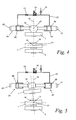
Figure 4 is a highly schematic section of the hinged joint fromfigure 3 according to line IV-IV in a neutral position. -
Figure 5 is the schematic section of the hinged joint fromfigure 4 whereby both frames of the vehicle according to the invention are rotated in relation to one another round an axis extending in the longitudinal direction of the vehicle. -
Figure 6 is a schematic view from above of a vehicle according to a variant embodiment of the vehicle according to the invention -
Figure 7 is a schematic view from above of a vehicle according to another embodiment of the vehicle according to the invention - In the different drawings, the same reference figures refer to identical or analogous elements.
-
Figures 1 and 2 schematically represent a shovel loader according to the present state of the art. This shovel loader has afirst frame 1 which is provided with a set of wheels with twowheels second frame 4 with a set ofwheels including wheels - The
first frame 1 forms the front part of the vehicle and is provided with a hydraulically operated lifting arm 7 on which is mounted aloading bucket 8. The rear part of the vehicle is formed by saidsecond frame 4 and has asteering wheel 9 and aseat 10 for the driver of the vehicle. Said rear part is further equipped with a hydraulic system, not represented in the drawings, which provides among others for the drive of the lifting arm 7, theloading bucket 8 and the steerage. Said steerage comprises ahydraulic cylinder 11 which can move thefirst frame 1 in relation to thesecond frame 4 round ahinge pin 12. When the vehicle is situated on a flat horizontal surface, saidhinge pin 12 will extend vertically and will be situated in a vertical plane ofsymmetry 14 extending in the longitudinal direction of thesecond frame 4. In this position, thehinge pin 12 is situated in what is called a neutral position. - The
first frame 1 is connected to thesecond frame 4 by means of ahinged joint 13. The latter makes it possible, among others, for thefirst frame 1 to move in relation to thesecond frame 4. In particular, thefirst frame 1 can be subjected to a rotation round thehinge pin 12 in relation to thesecond frame 4. In addition to this, thehinge pin 12 can also pivot round a point ofrotation 15 which forms the centre of aball joint 16. Thisball joint 16 connects thefirst frame 1 to thesecond frame 2, whereby the point ofrotation 15 thus has a fixed position in relation to both frames. - In said neutral position, a
hinge point 17 is situated practically vertically above the point ofrotation 15, whichhinge point 17 is fixed in relation to thefirst frame 1 and is hinge-mounted to arod 18. Thehinge point 17 as well as the point ofrotation 15 are situated on saidhinge pin 12. Therod 18 may be somewhat elastically deformable in its longitudinal direction. - The
hinge point 17 is situated in the centre of asecond ball joint 19 which forms a first far end of saidrod 18. The other far end of thisrod 18 is hinge-mounted to thesecond frame 4 in a point which is preferably situated in the vertical plane of symmetry of the latter, extending in the longitudinal direction. In particular, this other far end of therod 18 is preferably also formed of aball joint 20. - When the vehicle moves over rough ground, the
first frame 1 can thus undergo a rotation in relation to thesecond frame 4 round an axis ofrotation 21 situated in said plane ofsymmetry 14 and going through said point ofrotation 15. Thehinge pin 12 is thereby subjected to a pivoting movement round said point ofrotation 15, and thehinge point 17 describes an arc having saidball joint 20 as a centre. - If this vehicle rides over a bumpiness with one of the
front wheels loading bucket 8 being loaded, the first frame will be subjected to a sudden acceleration round said axis ofrotation 21, and it will move at a relatively high speed in relation to thesecond frame 4 until a maximum rotation of thefirst frame 1 in relation to thesecond frame 2 is reached, determined among others by saidrod 18. Consequently, the mass of this second frame cannot immediately stabilise the vehicle. As soon as the maximum rotation round the axis ofrotation 21 is reached, both frames form a rigid whole in said direction of rotation. Due to the inertia of the moving, filled loading bucket, the mass of the second frame will not suffice, however, to maintain the vehicle in a stable position, and consequently it will tip. - This situation is remedied thanks to the application of an interesting embodiment of the present invention as illustrated in
figures 3 to 5 . In particular,figure 3 shows the vehicle fromfigures 1 and 2 , whereby means are provided to dampen the movement of thefirst frame 1 in relation to thesecond frame 4. - In particular, these means comprise two liquid reservoirs which are filled with a hydraulic liquid and which are connected via a
hydraulic line 22 in which has been provided athrottle valve 23. During the movement of saidfirst frame 1 in relation to thesecond frame 4 round the axis ofrotation 21, said liquid is displaced between both reservoirs via thethrottle valve 23. - Each of these liquid reservoirs is situated in a corresponding
hydraulic cylinder cylinders respective supports second frame 4. The corresponding far ends of the respective piston rods of thesecylinders ball joint 19 on either side of the above-mentioned plane ofsymmetry 14. The axis of each of saidcylinders ball joint 19, such that said cylinders can exert a pressure force on theball joint 19. - When the
first frame 1 is subjected to a rotation round the axis ofrotation 15 in relation to thesecond frame 4, as represented infigure 5 , theball joint 19 will push against the piston rod of thehydraulic cylinder 24. This makes sure that theliquid reservoir 28 in the cylinder housing of thecylinder 24 is moved via theline 22 and thethrottle valve 23 to thereservoir 29 of the oppositehydraulic cylinder 25. - Thus, the piston rod of the
cylinder 24 will exert a pressure force on theball joint 19 which makes sure that the movement of thehinge pin 12 round the point ofrotation 15, and thus also the movement of the first frame in relation to the second frame, is slowed down. - In particular, the throttling of the flow of the hydraulic liquid through the throttle valve is adjusted such that, under normal working conditions, the dampening due to the displacement of the liquid is negligible, whereas in case of a quick and sudden movement of both frames in relation to one another round the axis of
rotation 15, said throttling will make sure that the movement is slowed down and that both frames form a practically rigid whole, at least approximately, such that the mass of thesecond frame 4 provides for stabilisation and prevents the vehicle from tipping. - The influence of the
throttle valve 23 is particularly negligible when the shovel loader is in a stable position. In such a case, while driving the vehicle, the force exerted by thecylinders hydraulic cylinder 11 of the latter. - It is clear that the dimensions of the piston rod and the cylinder housing of the
hydraulic cylinders hydraulic line 22 is normally selected in the order of magnitude of 3 to 4 mm, as is usually applied as standard in hydraulic systems. - When the hydraulic cylinder has a piston with a diameter (D) in the order of magnitude of 30 mm, it is found that an appropriate throttling in the
throttle valve 23 is obtained when the latter has a passage for the hydraulic liquid with a diameter (d) of about 0.6 mm. In the case of a hydraulic cylinder with a piston having a diameter (D) of 40 mm, the diameter (d) of the passage of thethrottle valve 23 will be preferably 0.8 mm. - More generally it can be said that, according to the invention, the D/d ratio of the diameter (D) of the piston in relation to the diameter (d) of the passage of the
throttle valve 23 is situated between 35 and 65. Preferably, this D/d ratio is in the order of magnitude of 50. - The diameter (d) of the passage of the
throttle valve 23 is preferably selected as a function of the allowed speed of movement of thehinge pin 12 in relation to thesecond frame 4, taking into account the diameter (D) of the piston of thehydraulic cylinders - The length of stroke of the piston rods is preferably in the order of magnitude of 9 cm, but it may deviate as a function of the allowed movement of the
first frame 1 in relation to thesecond frame 4. When the length of stroke amounts to 9 cm and the piston is moved over this length, a quantity of hydraulic liquid of some 63 cc will be displaced when the diameter of the piston amounts to 30 mm, and of some 113 cc when said diameter amounts to 40 mm. - It is indicated for the piston rods of both
hydraulic cylinders - Consequently, the
hydraulic cylinders hinge point 17 according to an arc which has said secondfar end 20 of saidrod 18 as a centre. - Although in the preceding embodiment, the piston rods rest freely on said ball joint 19, it is of course possible for said piston rods to be either fixed to the latter or directly to the
first frame 1 in the vicinity of saidhinge pin 12, thehinge point 17 or the ball joint 19 concerned. - Further, it is clear that the axis of said hydraulic cylinders must not necessarily touch the arc being described by the
hinge point 17, but that these cylinders should only be able to exert a force component according to a tangent to said arc. - The above-mentioned
hydraulic line 22 may further be provided with astop valve 30 which can prevent the displacement of liquid between said reservoirs of thehydraulic cylinders - Further, said hydraulic line is preferably connected to a hydraulic system via a
non-return valve 31 in order to bring the liquid in said reservoirs to a certain pressure, whereby the hydraulic liquid cannot flow back from said liquid reservoirs to the hydraulic system. - The hydraulic cylinders which are represented in
figures 3 to 5 may consist of single-acting hydraulic cylinders and are preferably formed of a piston cylinder. - According to an alternative embodiment of the vehicle according to the invention, said reservoirs are part of one and the same double-acting hydraulic cylinder which connects said first frame to a supporting point which has a practically fixed position in relation to said second frame in the vicinity of said hinge pin.
- Yet another embodiment of the vehicle according to the invention is represented in
figure 6 . In this embodiment is provided only onehydraulic cylinder 32 to dampen the movement of thefirst frame 1 in relation to thesecond frame 4. Thishydraulic cylinder 32 is formed of a double-acting cylinder which thus contains twoliquid reservoirs piston 33. Saidreservoirs throttle valve 23. - The
piston 33 of this double-actingcylinder 32 is fixed to apiston rod 34 of which one far end is connected to saidhinge point 17 or thus to the corresponding ball joint 19. Thus, this far end of thepiston rod 34 is hinge-mounted to aflange 35 which is fixed to said ball joint 19. - The cylinder housing of the
hydraulic cylinder 32 is connected to saidsecond frame 4 in ahinge point 36. - When the
first frame 1 moves in relation to thesecond frame 4, this movement will be dampened by the displacement of hydraulic liquid via thehydraulic line 22 and thecorresponding throttle valve 23 between saidliquid reservoirs - In a variant of this embodiment of the vehicle according to the invention, a
piston rod 34 of a double-actingcylinder 32 is fixed to saidsecond frame 4 viasupports figure 7 . Apiston 33 is fixed to thispiston rod 34 and divides the cylinder housing of thecylinder 32 in twoliquid reservoirs cylinder 32 thereby has twoflanges hinge point 17, and practically joining the latter. When thefirst frame 1 with the ball joint 19 is thus moved in relation to thesecond frame 4, said ball joint 19 will push against one of theflanges cylinder 32 moves along thepiston rod 34. Hydraulic liquid is thereby displaced between theliquid reservoirs hydraulic line 22 and athrottle valve 23, such that the movement of thefirst frame 1 in relation to thesecond frame 4 is dampened. - Naturally, with the double-acting hydraulic cylinders from
figures 6 and 7 , it is possible to integrate a throttle valve in the cylinder itself, for example in thepiston 33.
Claims (13)
- Vehicle, in particular a shovel loader, comprising a first frame (1) with a first set of wheels (2,3) and a second frame (4) with a second set of wheels (5,6), whereby the first frame (1) is connected to the second frame (4) by means of a hinged joint, such that the first frame (1) can move in relation to the second frame (4), whereby means are provided to dampen the movement of the first frame (1) in relation to the second frame (4), characterised in that said means comprise two liquid reservoirs (28,29) with a hydraulic liquid which are connected via a throttle valve (23), whereby during the movement of said first frame (1) in relation to the second frame (4) said liquid is displaced between both reservoirs (28,29) via said throttle valve (23).
- Vehicle according to claim 1, whereby said hinged joint has a hinge pin (12) around which the first frame (1) can rotate in relation to the second frame (4), whereby this hinge pin (12) can also pivot and said liquid reservoirs co-operate with this hinged joint, such that when the hinge pin (12) is moved in a direction crosswise to the longitudinal axis of the second frame (4), liquid is displaced between both reservoirs (28,29) via said throttle valve (23).
- Vehicle according to claim 1 or 2, whereby said reservoirs (28,29) are part of at least one hydraulic cylinder (24,25,32) connecting said first frame (1) to a supporting point (26,27) which has a practically fixed position in relation to said second frame (4) in the vicinity of said hinge pin (12).
- Vehicle according to claim 3, whereby said hydraulic cylinder (24,25,32) has a piston with a diameter (D), whereas said throttle valve (23) has a passage for said liquid with a diameter (d), whereby the (D/d) ratio of the diameter (D) of the piston in relation to the diameter (d) of the passage of the throttle valve (23) is situated between about 35 and about 65 and is in particular in the order of magnitude of about 50.
- Vehicle according to any one of claims 1 to 4, whereby said hinged joint has a hinge pin (12) which is determined by a point of rotation (15) on the one hand around which this hinge pin (12) can pivot and which has a fixed position in relation to both frames (1,4), and a hinge point (17) situated practically vertically above this point of rotation (15) on the other hand, which is fixed in relation to the first frame (1) and which is hinge-mounted to the first far end of a rod (18), whereas the second far end of this rod (18) is hinge-mounted to the second frame (4) in a point which is preferably situated in a plane of symmetry (14) of the latter extending vertically in the longitudinal direction, whereby said means dampen the movement of said hinge point (17) according to an arc having said second far end of the rod (18) as a centre.
- Vehicle according to claim 5, whereby said hinge point (17) forms the centre of a ball joint (19) which connects said first frame (1) to said rod (18), whereby each of the two liquid reservoirs (28,29) is further provided in a corresponding hydraulic cylinder (24,25,32), whereby the axis of each of these cylinders extends on either side of the ball joint (19), almost touching said arc, between the latter and a supporting point (26,27) on said second frame (4), such that these cylinders (24,25,32) can exert a pressure force between the supporting point (26,27) concerned and said ball joint (19).
- Vehicle according to any one of claims 1 to 6, whereby said reservoirs (26,27) are connected via a hydraulic line (22) in which said throttle valve (23) is provided and which further contains a stop valve (30) to prevent any displacement of liquid between said reservoirs (26,27).
- Vehicle according to any one of claims 1 to 6, whereby said liquid reservoirs (28,29) are connected to a hydraulic system in order to bring the liquid in said reservoirs (28,29) to a certain pressure, via a non-return valve (31), such that hydraulic liquid cannot flow back from said liquid reservoirs (28,29) to the hydraulic system.
- Method for stabilising a vehicle, in particular a shovel loader, comprising a first frame (1) with a first set of wheels (2,3) and a second frame (4) with a second set of wheels (5,6), whereby the first frame (1) is connected to the second frame (4) by means of a hinged joint,
whereby this hinged joint has a hinge pin (12) which is determined by a point of rotation (15) on the one hand around which this hinge pin (12) can pivot and having a fixed position in relation to both frames (1,4), and a hinge point (17) situated above this point of rotation (15) on the other hand which is fixed in relation to the first frame (1) and hinge-mounted to the first far end of a rod (18), whereas the second far end of this rod (18) is hinge-mounted to the second frame (4) in a point which is preferably situated in a vertical plane of symmetry (14) of the latter extending in the longitudinal direction,
characterised in that the movement of said hinge pin (12) in relation to the second frame (4) is dampened. - Method according to claim 9, whereby the movement of said hinge pin (12) is dampened by displacing a hydraulic liquid through a throttle valve (23).
- Method according to claim 10, whereby a diameter for the passage of said throttle valve (23) is selected such that the dampening of the movement of the hinge pin (12) through the throttle valve (23) is practically negligible when the speed of movement of said hinge pin (12) is lower than a preset value, whereby this movement of the hinge pin (12) is dampened when said predetermined value is exceeded.
- Method according to claim 10 or 11, whereby said hinge pin (12) co-operates with two liquid reservoirs (28,29) containing a hydraulic liquid, such that hydraulic liquid is displaced via said throttle valve (12) between both reservoirs (28,29) when said hinge pin (12) is moved.
- Method according to claim 12, whereby said reservoirs (28,29) are part of at least one hydraulic cylinder (24,25,32) connecting said first frame (1) to a supporting point (26,27) which has a practically fixed position in relation to said second frame (4) in the vicinity of said hinge pin (12), whereby said cylinder (24,25,32) is operated by the movement of the hinge pin (12).
Priority Applications (1)
| Application Number | Priority Date | Filing Date | Title |
|---|---|---|---|
| PL10447007T PL2218835T3 (en) | 2009-02-12 | 2010-02-12 | Shovel loader comprising two hinged frames. |
Applications Claiming Priority (2)
| Application Number | Priority Date | Filing Date | Title |
|---|---|---|---|
| BE2009/0079A BE1018654A3 (en) | 2009-02-12 | 2009-02-12 | LOADER. |
| BE200900481 | 2009-08-10 |
Publications (2)
| Publication Number | Publication Date |
|---|---|
| EP2218835A1 true EP2218835A1 (en) | 2010-08-18 |
| EP2218835B1 EP2218835B1 (en) | 2012-10-31 |
Family
ID=42153711
Family Applications (1)
| Application Number | Title | Priority Date | Filing Date |
|---|---|---|---|
| EP10447007A Active EP2218835B1 (en) | 2009-02-12 | 2010-02-12 | Shovel loader comprising two hinged frames. |
Country Status (3)
| Country | Link |
|---|---|
| EP (1) | EP2218835B1 (en) |
| DK (1) | DK2218835T3 (en) |
| PL (1) | PL2218835T3 (en) |
Cited By (11)
| Publication number | Priority date | Publication date | Assignee | Title |
|---|---|---|---|---|
| DE202016101145U1 (en) | 2016-03-03 | 2016-03-24 | Wacker Neuson Linz Gmbh | Electric powered dumper with energy storage unit |
| DE202016102237U1 (en) | 2016-04-27 | 2016-05-19 | Kramer-Werke Gmbh | Electric drive train for a work vehicle |
| DE202016101868U1 (en) | 2016-04-08 | 2016-07-08 | Wacker Neuson Linz Gmbh | Work vehicle with fold-out tilting edge |
| DE202016101740U1 (en) | 2016-04-01 | 2016-07-13 | Wacker Neuson Linz Gmbh | Work vehicle with protection |
| DE202016100964U1 (en) | 2016-02-24 | 2017-05-26 | Wacker Neuson Linz Gmbh | Work vehicle with revolving driver's seat |
| DE102016102857A1 (en) | 2016-02-18 | 2017-08-24 | Weidemann GmbH | Work vehicle with articulated pendulum joint damping |
| DE102016102854A1 (en) | 2016-02-18 | 2017-08-24 | Weidemann GmbH | Work vehicle with steerable articulated suspension joint damping and method for driving stabilization of the working vehicle |
| DE102016106459A1 (en) | 2016-04-08 | 2017-10-12 | Weidemann GmbH | Work vehicle with articulated steering and load-dependent steering angle limitation |
| EP4269201A1 (en) | 2022-04-28 | 2023-11-01 | Wacker Neuson Linz GmbH | Work vehicle with collision warning device |
| DE102023122064A1 (en) | 2023-08-17 | 2025-02-20 | Wacker Neuson Linz Gmbh | Work vehicle with rotating device for rotating a driver's cab |
| EP4647307A1 (en) | 2024-05-08 | 2025-11-12 | Wacker Neuson Linz GmbH | Work vehicle with automatic shut-off function for a brake assist device |
Families Citing this family (2)
| Publication number | Priority date | Publication date | Assignee | Title |
|---|---|---|---|---|
| CA3295285A1 (en) | 2016-09-15 | 2026-03-02 | Terex Australia Pty Ltd | Crane counterweight and suspension |
| CN115210130A (en) | 2020-01-30 | 2022-10-18 | 沃尔沃建筑设备公司 | Articulated work machine vehicle |
Citations (7)
| Publication number | Priority date | Publication date | Assignee | Title |
|---|---|---|---|---|
| JPS61116132A (en) * | 1984-11-09 | 1986-06-03 | Hitachi Ltd | vibration isolator |
| EP0266785A1 (en) * | 1986-11-05 | 1988-05-11 | Ahlmann Baumaschinen GmbH | Self-propelled multipurpose device |
| WO1990002681A1 (en) * | 1988-09-12 | 1990-03-22 | Lasse Karilainen | Transmission and articulation arrangement between a terrain vehicle and a trailer |
| FR2663590A1 (en) | 1990-06-21 | 1991-12-27 | Mecalac | Civil engineering works vehicle or the like including an articulated two-part chassis |
| FR2702012A1 (en) * | 1993-02-25 | 1994-09-02 | Sacmi | Hydraulic device for controlling the oscillations of a moving body and application to the oscillating train of a motor vehicle. |
| EP0803384A2 (en) * | 1996-04-24 | 1997-10-29 | Xaver Fendt GmbH & Co. | Device for limiting the oscillating motion of a rigid axle of a commercial vehicle, especially of an agricultural tractor |
| WO2005121594A2 (en) * | 2004-06-12 | 2005-12-22 | Siemens Aktiengesellschaft | An apparatus for damping the torsional excitation of a drive shaft |
-
2010
- 2010-02-12 EP EP10447007A patent/EP2218835B1/en active Active
- 2010-02-12 DK DK10447007.5T patent/DK2218835T3/en active
- 2010-02-12 PL PL10447007T patent/PL2218835T3/en unknown
Patent Citations (7)
| Publication number | Priority date | Publication date | Assignee | Title |
|---|---|---|---|---|
| JPS61116132A (en) * | 1984-11-09 | 1986-06-03 | Hitachi Ltd | vibration isolator |
| EP0266785A1 (en) * | 1986-11-05 | 1988-05-11 | Ahlmann Baumaschinen GmbH | Self-propelled multipurpose device |
| WO1990002681A1 (en) * | 1988-09-12 | 1990-03-22 | Lasse Karilainen | Transmission and articulation arrangement between a terrain vehicle and a trailer |
| FR2663590A1 (en) | 1990-06-21 | 1991-12-27 | Mecalac | Civil engineering works vehicle or the like including an articulated two-part chassis |
| FR2702012A1 (en) * | 1993-02-25 | 1994-09-02 | Sacmi | Hydraulic device for controlling the oscillations of a moving body and application to the oscillating train of a motor vehicle. |
| EP0803384A2 (en) * | 1996-04-24 | 1997-10-29 | Xaver Fendt GmbH & Co. | Device for limiting the oscillating motion of a rigid axle of a commercial vehicle, especially of an agricultural tractor |
| WO2005121594A2 (en) * | 2004-06-12 | 2005-12-22 | Siemens Aktiengesellschaft | An apparatus for damping the torsional excitation of a drive shaft |
Cited By (17)
| Publication number | Priority date | Publication date | Assignee | Title |
|---|---|---|---|---|
| DE102016102854A1 (en) | 2016-02-18 | 2017-08-24 | Weidemann GmbH | Work vehicle with steerable articulated suspension joint damping and method for driving stabilization of the working vehicle |
| DE102016102857A1 (en) | 2016-02-18 | 2017-08-24 | Weidemann GmbH | Work vehicle with articulated pendulum joint damping |
| EP3211141A2 (en) | 2016-02-24 | 2017-08-30 | Wacker Neuson Linz GmbH | Dumper with articulated steering and with a rotatable driver seat |
| DE202016100964U1 (en) | 2016-02-24 | 2017-05-26 | Wacker Neuson Linz Gmbh | Work vehicle with revolving driver's seat |
| DE202016101145U1 (en) | 2016-03-03 | 2016-03-24 | Wacker Neuson Linz Gmbh | Electric powered dumper with energy storage unit |
| DE202016101740U1 (en) | 2016-04-01 | 2016-07-13 | Wacker Neuson Linz Gmbh | Work vehicle with protection |
| DE102016106459A1 (en) | 2016-04-08 | 2017-10-12 | Weidemann GmbH | Work vehicle with articulated steering and load-dependent steering angle limitation |
| DE202016101868U1 (en) | 2016-04-08 | 2016-07-08 | Wacker Neuson Linz Gmbh | Work vehicle with fold-out tilting edge |
| US10112518B2 (en) | 2016-04-08 | 2018-10-30 | Wacker Neuson Linz Gmbh | Work vehicle with fold-out tipping edge |
| DE202016102237U1 (en) | 2016-04-27 | 2016-05-19 | Kramer-Werke Gmbh | Electric drive train for a work vehicle |
| DE102017004006A1 (en) | 2016-04-27 | 2017-11-02 | Kramer-Werke Gmbh | Electric drive train for a work vehicle |
| EP4269201A1 (en) | 2022-04-28 | 2023-11-01 | Wacker Neuson Linz GmbH | Work vehicle with collision warning device |
| DE102022110385A1 (en) | 2022-04-28 | 2023-11-02 | Wacker Neuson Linz Gmbh | Work vehicle with collision warning device |
| DE102023122064A1 (en) | 2023-08-17 | 2025-02-20 | Wacker Neuson Linz Gmbh | Work vehicle with rotating device for rotating a driver's cab |
| EP4516642A1 (en) | 2023-08-17 | 2025-03-05 | Wacker Neuson Linz GmbH | Work vehicle with turning device for turning a driver's canopy |
| EP4647307A1 (en) | 2024-05-08 | 2025-11-12 | Wacker Neuson Linz GmbH | Work vehicle with automatic shut-off function for a brake assist device |
| DE102024112935A1 (en) | 2024-05-08 | 2025-11-13 | Wacker Neuson Linz Gmbh | Work vehicle with automatic mute function for radar-based brake assist |
Also Published As
| Publication number | Publication date |
|---|---|
| PL2218835T3 (en) | 2013-04-30 |
| EP2218835B1 (en) | 2012-10-31 |
| DK2218835T3 (en) | 2013-02-11 |
Similar Documents
| Publication | Publication Date | Title |
|---|---|---|
| EP2218835B1 (en) | Shovel loader comprising two hinged frames. | |
| EP1975114B2 (en) | Oscillation compensation for the lifting frame of an industrial truck | |
| US9956842B2 (en) | System and method for controlling stability of milling machines | |
| DE60128599T2 (en) | implement | |
| EP2085299A2 (en) | Articulated vehicle stabilization system | |
| US5997013A (en) | Chassis stabilization system | |
| US7770909B2 (en) | Articulated vehicle stabilization system | |
| EP3571113B1 (en) | Work machine | |
| US20060232025A1 (en) | Control device for a truck having an oscillating axle | |
| DE10304658A1 (en) | Industrial truck | |
| DE112008000131T5 (en) | Transportation vehicle | |
| EP2544985B1 (en) | Self-moving operating machine with integrated lateral movement and leveling device | |
| DE3637709C2 (en) | ||
| DE60316762T2 (en) | Driver's cab cradle of a land vehicle | |
| DE102013113428A1 (en) | Truck | |
| US20120251283A1 (en) | Construction equipment machine with improved boom suspension | |
| WO2007058572A1 (en) | Suspension device for a vehicle component | |
| FI117795B (en) | Articulated vehicle stabilization | |
| DE3511336C2 (en) | ||
| EP3059104B1 (en) | A hydraulic cylinder arrangement, suspension arrangement as well as control arrangement for impact, noice and vibration absorbing suspension of an operator cab | |
| CN1867473A (en) | cab support | |
| EP1195470A1 (en) | Earth-moving machine | |
| JP5926114B2 (en) | Vehicle-mounted crane | |
| US8777543B2 (en) | Rollback carrier gravity tilt dampening system | |
| KR20110105549A (en) | Tilting structure of steering column for vehicle |
Legal Events
| Date | Code | Title | Description |
|---|---|---|---|
| PUAI | Public reference made under article 153(3) epc to a published international application that has entered the european phase |
Free format text: ORIGINAL CODE: 0009012 |
|
| AK | Designated contracting states |
Kind code of ref document: A1 Designated state(s): AT BE BG CH CY CZ DE DK EE ES FI FR GB GR HR HU IE IS IT LI LT LU LV MC MK MT NL NO PL PT RO SE SI SK SM TR |
|
| AX | Request for extension of the european patent |
Extension state: AL BA RS |
|
| 17P | Request for examination filed |
Effective date: 20110218 |
|
| 17Q | First examination report despatched |
Effective date: 20110513 |
|
| GRAP | Despatch of communication of intention to grant a patent |
Free format text: ORIGINAL CODE: EPIDOSNIGR1 |
|
| GRAS | Grant fee paid |
Free format text: ORIGINAL CODE: EPIDOSNIGR3 |
|
| GRAA | (expected) grant |
Free format text: ORIGINAL CODE: 0009210 |
|
| AK | Designated contracting states |
Kind code of ref document: B1 Designated state(s): AT BE BG CH CY CZ DE DK EE ES FI FR GB GR HR HU IE IS IT LI LT LU LV MC MK MT NL NO PL PT RO SE SI SK SM TR |
|
| REG | Reference to a national code |
Ref country code: GB Ref legal event code: FG4D Ref country code: CH Ref legal event code: EP |
|
| REG | Reference to a national code |
Ref country code: AT Ref legal event code: REF Ref document number: 582107 Country of ref document: AT Kind code of ref document: T Effective date: 20121115 |
|
| REG | Reference to a national code |
Ref country code: IE Ref legal event code: FG4D |
|
| REG | Reference to a national code |
Ref country code: DE Ref legal event code: R096 Ref document number: 602010003441 Country of ref document: DE Effective date: 20121227 |
|
| REG | Reference to a national code |
Ref country code: DK Ref legal event code: T3 |
|
| REG | Reference to a national code |
Ref country code: SE Ref legal event code: TRGR |
|
| REG | Reference to a national code |
Ref country code: NL Ref legal event code: T3 |
|
| RAP2 | Party data changed (patent owner data changed or rights of a patent transferred) |
Owner name: TOINE BROCK CONSTRUCTIE/MECHANISATIE B.V. |
|
| RIN2 | Information on inventor provided after grant (corrected) |
Inventor name: TOINE BROCK CONSTRUCTIE/MECHANISATIE B.V. |
|
| REG | Reference to a national code |
Ref country code: NO Ref legal event code: T2 Effective date: 20121031 |
|
| REG | Reference to a national code |
Ref country code: LT Ref legal event code: MG4D |
|
| REG | Reference to a national code |
Ref country code: NL Ref legal event code: SD Effective date: 20130402 |
|
| PG25 | Lapsed in a contracting state [announced via postgrant information from national office to epo] |
Ref country code: IS Free format text: LAPSE BECAUSE OF FAILURE TO SUBMIT A TRANSLATION OF THE DESCRIPTION OR TO PAY THE FEE WITHIN THE PRESCRIBED TIME-LIMIT Effective date: 20130228 Ref country code: LT Free format text: LAPSE BECAUSE OF FAILURE TO SUBMIT A TRANSLATION OF THE DESCRIPTION OR TO PAY THE FEE WITHIN THE PRESCRIBED TIME-LIMIT Effective date: 20121031 Ref country code: ES Free format text: LAPSE BECAUSE OF FAILURE TO SUBMIT A TRANSLATION OF THE DESCRIPTION OR TO PAY THE FEE WITHIN THE PRESCRIBED TIME-LIMIT Effective date: 20130211 Ref country code: HR Free format text: LAPSE BECAUSE OF FAILURE TO SUBMIT A TRANSLATION OF THE DESCRIPTION OR TO PAY THE FEE WITHIN THE PRESCRIBED TIME-LIMIT Effective date: 20121031 |
|
| REG | Reference to a national code |
Ref country code: PL Ref legal event code: T3 |
|
| REG | Reference to a national code |
Ref country code: GB Ref legal event code: 732E Free format text: REGISTERED BETWEEN 20130404 AND 20130410 |
|
| PG25 | Lapsed in a contracting state [announced via postgrant information from national office to epo] |
Ref country code: LV Free format text: LAPSE BECAUSE OF FAILURE TO SUBMIT A TRANSLATION OF THE DESCRIPTION OR TO PAY THE FEE WITHIN THE PRESCRIBED TIME-LIMIT Effective date: 20121031 Ref country code: SI Free format text: LAPSE BECAUSE OF FAILURE TO SUBMIT A TRANSLATION OF THE DESCRIPTION OR TO PAY THE FEE WITHIN THE PRESCRIBED TIME-LIMIT Effective date: 20121031 Ref country code: PT Free format text: LAPSE BECAUSE OF FAILURE TO SUBMIT A TRANSLATION OF THE DESCRIPTION OR TO PAY THE FEE WITHIN THE PRESCRIBED TIME-LIMIT Effective date: 20130228 Ref country code: GR Free format text: LAPSE BECAUSE OF FAILURE TO SUBMIT A TRANSLATION OF THE DESCRIPTION OR TO PAY THE FEE WITHIN THE PRESCRIBED TIME-LIMIT Effective date: 20130201 |
|
| REG | Reference to a national code |
Ref country code: AT Ref legal event code: PC Ref document number: 582107 Country of ref document: AT Kind code of ref document: T Owner name: TOINE BROCK CONSTRUCTIE/MECHANISATIE B.V., NL Effective date: 20130506 |
|
| REG | Reference to a national code |
Ref country code: DE Ref legal event code: R081 Ref document number: 602010003441 Country of ref document: DE Owner name: TOINE BROCK CONSTRUCTIE/MECHANISATIE B.V., NL Free format text: FORMER OWNER: DIDDEN, LUC, LAAKDAL, BE Effective date: 20130429 |
|
| PG25 | Lapsed in a contracting state [announced via postgrant information from national office to epo] |
Ref country code: EE Free format text: LAPSE BECAUSE OF FAILURE TO SUBMIT A TRANSLATION OF THE DESCRIPTION OR TO PAY THE FEE WITHIN THE PRESCRIBED TIME-LIMIT Effective date: 20121031 Ref country code: SK Free format text: LAPSE BECAUSE OF FAILURE TO SUBMIT A TRANSLATION OF THE DESCRIPTION OR TO PAY THE FEE WITHIN THE PRESCRIBED TIME-LIMIT Effective date: 20121031 Ref country code: BG Free format text: LAPSE BECAUSE OF FAILURE TO SUBMIT A TRANSLATION OF THE DESCRIPTION OR TO PAY THE FEE WITHIN THE PRESCRIBED TIME-LIMIT Effective date: 20130131 |
|
| PG25 | Lapsed in a contracting state [announced via postgrant information from national office to epo] |
Ref country code: RO Free format text: LAPSE BECAUSE OF FAILURE TO SUBMIT A TRANSLATION OF THE DESCRIPTION OR TO PAY THE FEE WITHIN THE PRESCRIBED TIME-LIMIT Effective date: 20121031 |
|
| PLBE | No opposition filed within time limit |
Free format text: ORIGINAL CODE: 0009261 |
|
| STAA | Information on the status of an ep patent application or granted ep patent |
Free format text: STATUS: NO OPPOSITION FILED WITHIN TIME LIMIT |
|
| PG25 | Lapsed in a contracting state [announced via postgrant information from national office to epo] |
Ref country code: MC Free format text: LAPSE BECAUSE OF NON-PAYMENT OF DUE FEES Effective date: 20130228 |
|
| 26N | No opposition filed |
Effective date: 20130801 |
|
| REG | Reference to a national code |
Ref country code: DE Ref legal event code: R097 Ref document number: 602010003441 Country of ref document: DE Effective date: 20130801 |
|
| PG25 | Lapsed in a contracting state [announced via postgrant information from national office to epo] |
Ref country code: CY Free format text: LAPSE BECAUSE OF FAILURE TO SUBMIT A TRANSLATION OF THE DESCRIPTION OR TO PAY THE FEE WITHIN THE PRESCRIBED TIME-LIMIT Effective date: 20121031 |
|
| REG | Reference to a national code |
Ref country code: IE Ref legal event code: MM4A |
|
| PG25 | Lapsed in a contracting state [announced via postgrant information from national office to epo] |
Ref country code: IE Free format text: LAPSE BECAUSE OF NON-PAYMENT OF DUE FEES Effective date: 20130212 |
|
| PG25 | Lapsed in a contracting state [announced via postgrant information from national office to epo] |
Ref country code: MT Free format text: LAPSE BECAUSE OF FAILURE TO SUBMIT A TRANSLATION OF THE DESCRIPTION OR TO PAY THE FEE WITHIN THE PRESCRIBED TIME-LIMIT Effective date: 20121031 |
|
| PG25 | Lapsed in a contracting state [announced via postgrant information from national office to epo] |
Ref country code: SM Free format text: LAPSE BECAUSE OF FAILURE TO SUBMIT A TRANSLATION OF THE DESCRIPTION OR TO PAY THE FEE WITHIN THE PRESCRIBED TIME-LIMIT Effective date: 20121031 |
|
| PG25 | Lapsed in a contracting state [announced via postgrant information from national office to epo] |
Ref country code: HU Free format text: LAPSE BECAUSE OF FAILURE TO SUBMIT A TRANSLATION OF THE DESCRIPTION OR TO PAY THE FEE WITHIN THE PRESCRIBED TIME-LIMIT; INVALID AB INITIO Effective date: 20100212 Ref country code: MK Free format text: LAPSE BECAUSE OF FAILURE TO SUBMIT A TRANSLATION OF THE DESCRIPTION OR TO PAY THE FEE WITHIN THE PRESCRIBED TIME-LIMIT Effective date: 20121031 |
|
| REG | Reference to a national code |
Ref country code: FR Ref legal event code: PLFP Year of fee payment: 7 |
|
| REG | Reference to a national code |
Ref country code: FR Ref legal event code: PLFP Year of fee payment: 8 |
|
| PGFP | Annual fee paid to national office [announced via postgrant information from national office to epo] |
Ref country code: TR Payment date: 20170201 Year of fee payment: 8 |
|
| REG | Reference to a national code |
Ref country code: FR Ref legal event code: PLFP Year of fee payment: 9 |
|
| PGFP | Annual fee paid to national office [announced via postgrant information from national office to epo] |
Ref country code: LU Payment date: 20180227 Year of fee payment: 9 |
|
| PGFP | Annual fee paid to national office [announced via postgrant information from national office to epo] |
Ref country code: CZ Payment date: 20180208 Year of fee payment: 9 |
|
| PG25 | Lapsed in a contracting state [announced via postgrant information from national office to epo] |
Ref country code: LU Free format text: LAPSE BECAUSE OF NON-PAYMENT OF DUE FEES Effective date: 20190212 Ref country code: CZ Free format text: LAPSE BECAUSE OF NON-PAYMENT OF DUE FEES Effective date: 20190212 |
|
| PGFP | Annual fee paid to national office [announced via postgrant information from national office to epo] |
Ref country code: PL Payment date: 20200121 Year of fee payment: 11 |
|
| PG25 | Lapsed in a contracting state [announced via postgrant information from national office to epo] |
Ref country code: TR Free format text: LAPSE BECAUSE OF NON-PAYMENT OF DUE FEES Effective date: 20180212 |
|
| PG25 | Lapsed in a contracting state [announced via postgrant information from national office to epo] |
Ref country code: PL Free format text: LAPSE BECAUSE OF NON-PAYMENT OF DUE FEES Effective date: 20210212 |
|
| REG | Reference to a national code |
Ref country code: CH Ref legal event code: U11 Free format text: ST27 STATUS EVENT CODE: U-0-0-U10-U11 (AS PROVIDED BY THE NATIONAL OFFICE) Effective date: 20260301 |
|
| PGFP | Annual fee paid to national office [announced via postgrant information from national office to epo] |
Ref country code: NL Payment date: 20260226 Year of fee payment: 17 |
|
| PGFP | Annual fee paid to national office [announced via postgrant information from national office to epo] |
Ref country code: SE Payment date: 20260227 Year of fee payment: 17 |
|
| PGFP | Annual fee paid to national office [announced via postgrant information from national office to epo] |
Ref country code: GB Payment date: 20260227 Year of fee payment: 17 |
|
| PGFP | Annual fee paid to national office [announced via postgrant information from national office to epo] |
Ref country code: NO Payment date: 20260227 Year of fee payment: 17 Ref country code: DK Payment date: 20260225 Year of fee payment: 17 Ref country code: DE Payment date: 20260227 Year of fee payment: 17 |
|
| PGFP | Annual fee paid to national office [announced via postgrant information from national office to epo] |
Ref country code: AT Payment date: 20260227 Year of fee payment: 17 |
|
| PGFP | Annual fee paid to national office [announced via postgrant information from national office to epo] |
Ref country code: BE Payment date: 20260227 Year of fee payment: 17 Ref country code: FI Payment date: 20260225 Year of fee payment: 17 Ref country code: IT Payment date: 20260219 Year of fee payment: 17 |
|
| PGFP | Annual fee paid to national office [announced via postgrant information from national office to epo] |
Ref country code: FR Payment date: 20260225 Year of fee payment: 17 |
|
| PGFP | Annual fee paid to national office [announced via postgrant information from national office to epo] |
Ref country code: CH Payment date: 20260301 Year of fee payment: 17 |