EP2221474A1 - Offshore wind park - Google Patents
Offshore wind park Download PDFInfo
- Publication number
- EP2221474A1 EP2221474A1 EP09153330A EP09153330A EP2221474A1 EP 2221474 A1 EP2221474 A1 EP 2221474A1 EP 09153330 A EP09153330 A EP 09153330A EP 09153330 A EP09153330 A EP 09153330A EP 2221474 A1 EP2221474 A1 EP 2221474A1
- Authority
- EP
- European Patent Office
- Prior art keywords
- wind
- wind farm
- wind turbines
- buoyant structure
- columns
- Prior art date
- Legal status (The legal status is an assumption and is not a legal conclusion. Google has not performed a legal analysis and makes no representation as to the accuracy of the status listed.)
- Withdrawn
Links
Images
Classifications
-
- F—MECHANICAL ENGINEERING; LIGHTING; HEATING; WEAPONS; BLASTING
- F03—MACHINES OR ENGINES FOR LIQUIDS; WIND, SPRING, OR WEIGHT MOTORS; PRODUCING MECHANICAL POWER OR A REACTIVE PROPULSIVE THRUST, NOT OTHERWISE PROVIDED FOR
- F03D—WIND MOTORS
- F03D1/00—Wind motors with rotation axis substantially parallel to the air flow entering the rotor
-
- F—MECHANICAL ENGINEERING; LIGHTING; HEATING; WEAPONS; BLASTING
- F03—MACHINES OR ENGINES FOR LIQUIDS; WIND, SPRING, OR WEIGHT MOTORS; PRODUCING MECHANICAL POWER OR A REACTIVE PROPULSIVE THRUST, NOT OTHERWISE PROVIDED FOR
- F03D—WIND MOTORS
- F03D7/00—Controlling wind motors
- F03D7/02—Controlling wind motors the wind motors having rotation axis substantially parallel to the air flow entering the rotor
- F03D7/0204—Controlling wind motors the wind motors having rotation axis substantially parallel to the air flow entering the rotor for orientation in relation to wind direction
-
- B—PERFORMING OPERATIONS; TRANSPORTING
- B63—SHIPS OR OTHER WATERBORNE VESSELS; RELATED EQUIPMENT
- B63B—SHIPS OR OTHER WATERBORNE VESSELS; EQUIPMENT FOR SHIPPING
- B63B1/00—Hydrodynamic or hydrostatic features of hulls or of hydrofoils
-
- B—PERFORMING OPERATIONS; TRANSPORTING
- B63—SHIPS OR OTHER WATERBORNE VESSELS; RELATED EQUIPMENT
- B63B—SHIPS OR OTHER WATERBORNE VESSELS; EQUIPMENT FOR SHIPPING
- B63B1/00—Hydrodynamic or hydrostatic features of hulls or of hydrofoils
- B63B1/02—Hydrodynamic or hydrostatic features of hulls or of hydrofoils deriving lift mainly from water displacement
- B63B1/10—Hydrodynamic or hydrostatic features of hulls or of hydrofoils deriving lift mainly from water displacement with multiple hulls
- B63B1/107—Semi-submersibles; Small waterline area multiple hull vessels and the like, e.g. SWATH
-
- B—PERFORMING OPERATIONS; TRANSPORTING
- B63—SHIPS OR OTHER WATERBORNE VESSELS; RELATED EQUIPMENT
- B63B—SHIPS OR OTHER WATERBORNE VESSELS; EQUIPMENT FOR SHIPPING
- B63B35/00—Vessels or similar floating structures specially adapted for specific purposes and not otherwise provided for
- B63B35/44—Floating buildings, stores, drilling platforms, or workshops, e.g. carrying water-oil separating devices
-
- F—MECHANICAL ENGINEERING; LIGHTING; HEATING; WEAPONS; BLASTING
- F03—MACHINES OR ENGINES FOR LIQUIDS; WIND, SPRING, OR WEIGHT MOTORS; PRODUCING MECHANICAL POWER OR A REACTIVE PROPULSIVE THRUST, NOT OTHERWISE PROVIDED FOR
- F03D—WIND MOTORS
- F03D13/00—Assembly, mounting or commissioning of wind motors; Arrangements specially adapted for transporting wind motor components
- F03D13/10—Assembly of wind motors; Arrangements for erecting wind motors
-
- F—MECHANICAL ENGINEERING; LIGHTING; HEATING; WEAPONS; BLASTING
- F03—MACHINES OR ENGINES FOR LIQUIDS; WIND, SPRING, OR WEIGHT MOTORS; PRODUCING MECHANICAL POWER OR A REACTIVE PROPULSIVE THRUST, NOT OTHERWISE PROVIDED FOR
- F03D—WIND MOTORS
- F03D13/00—Assembly, mounting or commissioning of wind motors; Arrangements specially adapted for transporting wind motor components
- F03D13/20—Arrangements for mounting or supporting wind motors; Masts or towers for wind motors
- F03D13/25—Arrangements for mounting or supporting wind motors; Masts or towers for wind motors specially adapted for offshore installation
-
- B—PERFORMING OPERATIONS; TRANSPORTING
- B63—SHIPS OR OTHER WATERBORNE VESSELS; RELATED EQUIPMENT
- B63B—SHIPS OR OTHER WATERBORNE VESSELS; EQUIPMENT FOR SHIPPING
- B63B1/00—Hydrodynamic or hydrostatic features of hulls or of hydrofoils
- B63B1/02—Hydrodynamic or hydrostatic features of hulls or of hydrofoils deriving lift mainly from water displacement
- B63B1/10—Hydrodynamic or hydrostatic features of hulls or of hydrofoils deriving lift mainly from water displacement with multiple hulls
- B63B1/12—Hydrodynamic or hydrostatic features of hulls or of hydrofoils deriving lift mainly from water displacement with multiple hulls the hulls being interconnected rigidly
- B63B2001/128—Hydrodynamic or hydrostatic features of hulls or of hydrofoils deriving lift mainly from water displacement with multiple hulls the hulls being interconnected rigidly comprising underwater connectors between the hulls
-
- B—PERFORMING OPERATIONS; TRANSPORTING
- B63—SHIPS OR OTHER WATERBORNE VESSELS; RELATED EQUIPMENT
- B63B—SHIPS OR OTHER WATERBORNE VESSELS; EQUIPMENT FOR SHIPPING
- B63B35/00—Vessels or similar floating structures specially adapted for specific purposes and not otherwise provided for
- B63B35/44—Floating buildings, stores, drilling platforms, or workshops, e.g. carrying water-oil separating devices
- B63B2035/4433—Floating structures carrying electric power plants
- B63B2035/446—Floating structures carrying electric power plants for converting wind energy into electric energy
-
- F—MECHANICAL ENGINEERING; LIGHTING; HEATING; WEAPONS; BLASTING
- F05—INDEXING SCHEMES RELATING TO ENGINES OR PUMPS IN VARIOUS SUBCLASSES OF CLASSES F01-F04
- F05B—INDEXING SCHEME RELATING TO WIND, SPRING, WEIGHT, INERTIA OR LIKE MOTORS, TO MACHINES OR ENGINES FOR LIQUIDS COVERED BY SUBCLASSES F03B, F03D AND F03G
- F05B2240/00—Components
- F05B2240/90—Mounting on supporting structures or systems
- F05B2240/93—Mounting on supporting structures or systems on a structure floating on a liquid surface
-
- F—MECHANICAL ENGINEERING; LIGHTING; HEATING; WEAPONS; BLASTING
- F05—INDEXING SCHEMES RELATING TO ENGINES OR PUMPS IN VARIOUS SUBCLASSES OF CLASSES F01-F04
- F05B—INDEXING SCHEME RELATING TO WIND, SPRING, WEIGHT, INERTIA OR LIKE MOTORS, TO MACHINES OR ENGINES FOR LIQUIDS COVERED BY SUBCLASSES F03B, F03D AND F03G
- F05B2240/00—Components
- F05B2240/90—Mounting on supporting structures or systems
- F05B2240/95—Mounting on supporting structures or systems offshore
-
- F—MECHANICAL ENGINEERING; LIGHTING; HEATING; WEAPONS; BLASTING
- F05—INDEXING SCHEMES RELATING TO ENGINES OR PUMPS IN VARIOUS SUBCLASSES OF CLASSES F01-F04
- F05B—INDEXING SCHEME RELATING TO WIND, SPRING, WEIGHT, INERTIA OR LIKE MOTORS, TO MACHINES OR ENGINES FOR LIQUIDS COVERED BY SUBCLASSES F03B, F03D AND F03G
- F05B2240/00—Components
- F05B2240/90—Mounting on supporting structures or systems
- F05B2240/96—Mounting on supporting structures or systems as part of a wind turbine farm
-
- Y—GENERAL TAGGING OF NEW TECHNOLOGICAL DEVELOPMENTS; GENERAL TAGGING OF CROSS-SECTIONAL TECHNOLOGIES SPANNING OVER SEVERAL SECTIONS OF THE IPC; TECHNICAL SUBJECTS COVERED BY FORMER USPC CROSS-REFERENCE ART COLLECTIONS [XRACs] AND DIGESTS
- Y02—TECHNOLOGIES OR APPLICATIONS FOR MITIGATION OR ADAPTATION AGAINST CLIMATE CHANGE
- Y02E—REDUCTION OF GREENHOUSE GAS [GHG] EMISSIONS, RELATED TO ENERGY GENERATION, TRANSMISSION OR DISTRIBUTION
- Y02E10/00—Energy generation through renewable energy sources
- Y02E10/70—Wind energy
- Y02E10/72—Wind turbines with rotation axis in wind direction
-
- Y—GENERAL TAGGING OF NEW TECHNOLOGICAL DEVELOPMENTS; GENERAL TAGGING OF CROSS-SECTIONAL TECHNOLOGIES SPANNING OVER SEVERAL SECTIONS OF THE IPC; TECHNICAL SUBJECTS COVERED BY FORMER USPC CROSS-REFERENCE ART COLLECTIONS [XRACs] AND DIGESTS
- Y02—TECHNOLOGIES OR APPLICATIONS FOR MITIGATION OR ADAPTATION AGAINST CLIMATE CHANGE
- Y02E—REDUCTION OF GREENHOUSE GAS [GHG] EMISSIONS, RELATED TO ENERGY GENERATION, TRANSMISSION OR DISTRIBUTION
- Y02E10/00—Energy generation through renewable energy sources
- Y02E10/70—Wind energy
- Y02E10/727—Offshore wind turbines
Definitions
- the invention relates to a wind farm or wind park comprising two or more wind turbines.
- buoyant foundations can be used, such as the WindFloat® system of the US company Marine Innovation & Technology.
- a minimum distance between the wind turbines is required to prevent that turbulence caused by a wind mill would disturb the wind flow impinging an adjacent wind turbine.
- the minimum distance would be substantially less if the wind turbines would have a parallel rotor axis.
- wind turbines are typically provided with yaw systems allowing them to turn with the wind and to maintain an upwind or downwind orientation with every wind direction to maximize energy efficiency. As a result, the wind turbines cannot constantly be maintained in a parallel orientation.
- the object of the invention is to enhance the energy yield of an offshore wind park of a given size.
- a further object is to provide a high yield wind park with wind turbines of a simple construction.
- offshore means any location on water, e.g., at sea, ocean or a lake, near shore or far offshore.
- a wind park comprising one or more buoyant structures, wherein at least a part of the buoyant structures carries two or more wind turbines.
- the wind turbines have a fixed orientation relative to the buoyant structure, wherein the wind turbines each comprise a rotor with one or more rotor blades defining plane of rotation, wherein the planes of rotation of the wind turbines are within the same plane.
- the rotor blades define a plane of rotation, it is not required that the blades have parallel straight longitudinal axes.
- the blades may wholly or partially be curved, twisted and/or coned relative to the hub, if so desired. However, in the overall impression the blades will define a plane of rotation.
- the buoyant structure can be rotated to position the wind turbines in an upwind or downwind position.
- the structure can for example comprise a mooring section for mooring lines anchoring the floating structure to a sea bed. This mooring section can form a point or rotation.
- Turret mooring systems are particularly suitable.
- a turret mooring system is a mooring system where lines are connected to a turret which via bearings allows the buoyant structure to rotate around the anchor legs.
- Single-point mooring systems permit the buoyant structure to weathervane to the desired upwind or downwind position.
- the structure may be provided with one or more drive units, e.g., one or more thrusters on one or more of the corners, for a more exact positioning of the buoyant structure. Since no yaw mechanism is needed, the wind turbines contains less moving parts and requires less maintenance and repair.
- the buoyant stricture can for example comprise three or more corners with two wind turbines being positioned on two corners, and wherein the mooring section is located on the third corner, or on a further free corner.
- the wind farm can for example comprise electrical equipment, such as a converter and/or transformer, shared by both wind turbines, the electrical equipment being located on or near the third corner, or a further free corner, of the buoyant structure.
- electrical equipment such as a converter and/or transformer
- Other shared facilities can also be present on the buoyant structure, such as a helideck.
- a shared helideck has the advantage that with each flight two wind turbines can be serviced. The number of flights needed for maintenance of the wind turbines can substantially be reduced.
- the buoyant structure can have a center of gravity located at or above its center of buoyancy.
- the structure can for instance comprise two or more vertical columns and a submerged horizontal water entrapment plate attached to the lower end of each column, extending outwardly such as to form a section of a circle or a polygon around the base of each column, wherein the water entrapment plate area exceeds the cross-sectional area of the stabilizing column upon which it is attached, and wherein the water entrapment plate is supported by a plurality of radial beams each connected at one end to the base of the columns, and at the other end to the edges of the water entrapment plate, and transverse beams each connected at its both ends to the base of the columns and providing continuous support to the water entrapment plate.
- the buoyant structure comprises a deck attached to the upper ends or the columns, and/or it can be provided with walkways between the columns.
- Such a buoyant structure can for example comprise three columns disposed about a vertical axis to form a triangle, or it may have four columns disposed about a vertical axis to form a quadrilateral. Other configurations can also be used, if so desired.
- the wind turbines typically comprise a tower carrying a gondola or nacelle with a rotor hub carrying a rotor with at least one rotor blade. Wind force on the one or more blades induces rotation of the rotor which is linked, e.g., gearless or via a gear transmission, to a generator, which can for example be located in the nacelle.
- the buoyant structure can comprise a buoyant substructure, a deck supporting minimum offshore facilities and / or an umbilical between the structure and possible subsea facilities beneath the buoyant structure.
- the substructure can comprise a plurality of vertical buoyant columns attached to a horizontal water entrapment plate at their lower end and to a deck that supports facilities at their upper end.
- the horizontal plate can extend radially from each column to cover the area formed by the center of the columns base.
- the buoyant structure can for example comprise further facilities such as antennas and other communication equipment to exchange information with a host platform, a helideck, storage and distribution systems, overnight accommodations for maintenance personnel, a crane or gantry to move equipment on the deck, a winch, or the like.
- the buoyant structure can be a column-stabilized unit with a large water-entrapment plate attached at the base of the columns.
- the submerged horizontal water entrapment plate can be designed to provide increased resistance to vertical accelerations and to roll and pitch rotational accelerations. Large amounts of water are displaced as the plate tends to move vertically. The mass of this displaced water is of the same order or larger than the mass of the buoyant structure.
- the total area of the plate is several times the cross-sectional area of the columns. The plate size and shape is adjusted so that it can compensate not only for heave, but also for strong wind force acting upon the carried wind turbines. This ensures that the motion of the buoyant structure remains small during normal operation.
- the plate can extend radially from each column forming a section of a polygon.
- the radial distance can be adjusted to control the natural roll and pitch period.
- the overall plate area is adjusted to control the heave natural period.
- no support to other parts of the hull is available near the plate outer edge, and therefore the water-entrapment plate must be cantilevered from the column.
- large structural supports are required to ensure the integrity of the plate and of its connection to the column.
- Such a buoyant structure is suitable to dampen wave and turbine motion, enabling wind turbines to be sited in previously inaccessible locations with strong winds.
- a suitable construction for a buoyant structure is for example disclosed in US 7281881 .
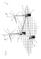
- FIG. 1 shows a perspective view on an offshore wind farm 1 according to the present invention.
- the wind farm 1 comprises a buoyant structure 2 carrying two wind turbines 3.
- the wind turbines 3 comprise a tower 4 carrying a gondola or nacelle 5 with a rotor 6 comprising a hub 7 carrying three rotor blades 8.
- Wind force impinging the rotor blades 7 induces rotation of the rotor 6 which is linked, e.g., gearless or via a gear transmission, to a generator located in the nacelle, converting the mechanical energy of the rotor into electrical energy, which is fed into a utility grid.
- the rotor blades 7 of each wind turbine 3 define plane of rotation. As shown in Figure 1 , these planes of rotation of both wind turbines lay within the same plane.
- the wind turbines 3 have a fixed orientation relative to the buoyant structure 2 and do not have a yaw mechanism.
- the buoyant structure 2 has a center of gravity located above its center of buoyancy.
- the structure 2 comprises three vertical columns 10 in a triangular arrangement. Attached to the lower end of each these columns 10 is a submerged horizontal water entrapment plate (not shown) extending outwardly such as to form a section of a circle or a polygon around the base of each column 3.
- the water entrapment plate area exceeds the cross-sectional area of the stabilizing column 3 upon which it is attached.
- the water entrapment plate is supported by a plurality of radial beams each connected at one end to the base of the columns 3, and at the other end to the edges of the water entrapment plate, and transverse beams each connected at its both ends to the base of the columns and providing continuous support to the water entrapment plate.
- the three columns 10 form a triangle.
- the tops or the columns 10 form a deck 20.
- Two or these decks 20 carry a wind turbine 3.
- the deck 20 on the third corner 21 may carry shared facilities, such as a common converter or transformer used for both wind turbines and/or a shared helideck or the like (not shown).
- the deck 20 on the third corner 21 is also used as a mooring section for attaching mooring lines anchoring the floating structure 2 to the sea bed.
- the floating structure 2 can rotate around the third corner. Wind force will orient the buoyant structure 2 with the wind turbines 3 to an upwind orientation.
- the three columns 10 are linked by a frame 22.
Landscapes
- Engineering & Computer Science (AREA)
- Chemical & Material Sciences (AREA)
- Mechanical Engineering (AREA)
- Combustion & Propulsion (AREA)
- Sustainable Energy (AREA)
- Life Sciences & Earth Sciences (AREA)
- Sustainable Development (AREA)
- General Engineering & Computer Science (AREA)
- Ocean & Marine Engineering (AREA)
- Physics & Mathematics (AREA)
- Fluid Mechanics (AREA)
- Architecture (AREA)
- Civil Engineering (AREA)
- Structural Engineering (AREA)
- Wind Motors (AREA)
Abstract
Description
- The invention relates to a wind farm or wind park comprising two or more wind turbines.
- Offshore locations are particularly useful for wind parks, since higher wind energy yields can be obtained than on shore and there are less spatial restrictions. To build offshore wind parks, buoyant foundations can be used, such as the WindFloat® system of the US company Marine Innovation & Technology.
- In offshore wind farms or wind parks, a minimum distance between the wind turbines is required to prevent that turbulence caused by a wind mill would disturb the wind flow impinging an adjacent wind turbine. The minimum distance would be substantially less if the wind turbines would have a parallel rotor axis. However, wind turbines are typically provided with yaw systems allowing them to turn with the wind and to maintain an upwind or downwind orientation with every wind direction to maximize energy efficiency. As a result, the wind turbines cannot constantly be maintained in a parallel orientation.
- The object of the invention is to enhance the energy yield of an offshore wind park of a given size. A further object is to provide a high yield wind park with wind turbines of a simple construction.
- In this context, offshore means any location on water, e.g., at sea, ocean or a lake, near shore or far offshore.
- The object of the invention is achieved by a wind park comprising one or more buoyant structures, wherein at least a part of the buoyant structures carries two or more wind turbines. Preferably, the wind turbines have a fixed orientation relative to the buoyant structure, wherein the wind turbines each comprise a rotor with one or more rotor blades defining plane of rotation, wherein the planes of rotation of the wind turbines are within the same plane. This way, the turbulence caused by the wind turbines does not disturb the wind flow impacting the neighboring wind turbine, so the wind turbines can stand closer together. As a result, not only the energy yield per buoyant structure is doubled, but also more wind turbines per surface area can be used and a compact wind farm with high turbine density can be realized.
- While the rotor blades define a plane of rotation, it is not required that the blades have parallel straight longitudinal axes. The blades may wholly or partially be curved, twisted and/or coned relative to the hub, if so desired. However, in the overall impression the blades will define a plane of rotation.
- Since the wind turbines have a fixed orientation relative to the floating structure they do not need to have a yaw mechanism. The buoyant structure can be rotated to position the wind turbines in an upwind or downwind position. The structure can for example comprise a mooring section for mooring lines anchoring the floating structure to a sea bed. This mooring section can form a point or rotation. Turret mooring systems are particularly suitable. A turret mooring system is a mooring system where lines are connected to a turret which via bearings allows the buoyant structure to rotate around the anchor legs.
- Single-point mooring systems permit the buoyant structure to weathervane to the desired upwind or downwind position. Optionally, the structure may be provided with one or more drive units, e.g., one or more thrusters on one or more of the corners, for a more exact positioning of the buoyant structure. Since no yaw mechanism is needed, the wind turbines contains less moving parts and requires less maintenance and repair.
- The buoyant stricture can for example comprise three or more corners with two wind turbines being positioned on two corners, and wherein the mooring section is located on the third corner, or on a further free corner.
- The wind farm can for example comprise electrical equipment, such as a converter and/or transformer, shared by both wind turbines, the electrical equipment being located on or near the third corner, or a further free corner, of the buoyant structure. Other shared facilities can also be present on the buoyant structure, such as a helideck. A shared helideck has the advantage that with each flight two wind turbines can be serviced. The number of flights needed for maintenance of the wind turbines can substantially be reduced.
- In a specific embodiment, the buoyant structure can have a center of gravity located at or above its center of buoyancy. The structure can for instance comprise two or more vertical columns and a submerged horizontal water entrapment plate attached to the lower end of each column, extending outwardly such as to form a section of a circle or a polygon around the base of each column, wherein the water entrapment plate area exceeds the cross-sectional area of the stabilizing column upon which it is attached, and wherein the water entrapment plate is supported by a plurality of radial beams each connected at one end to the base of the columns, and at the other end to the edges of the water entrapment plate, and transverse beams each connected at its both ends to the base of the columns and providing continuous support to the water entrapment plate.
- Optionally, the buoyant structure comprises a deck attached to the upper ends or the columns, and/or it can be provided with walkways between the columns.
- Such a buoyant structure can for example comprise three columns disposed about a vertical axis to form a triangle, or it may have four columns disposed about a vertical axis to form a quadrilateral. Other configurations can also be used, if so desired.
- The wind turbines typically comprise a tower carrying a gondola or nacelle with a rotor hub carrying a rotor with at least one rotor blade. Wind force on the one or more blades induces rotation of the rotor which is linked, e.g., gearless or via a gear transmission, to a generator, which can for example be located in the nacelle.
- The buoyant structure can comprise a buoyant substructure, a deck supporting minimum offshore facilities and / or an umbilical between the structure and possible subsea facilities beneath the buoyant structure. The substructure can comprise a plurality of vertical buoyant columns attached to a horizontal water entrapment plate at their lower end and to a deck that supports facilities at their upper end. The horizontal plate can extend radially from each column to cover the area formed by the center of the columns base. The buoyant structure can for example comprise further facilities such as antennas and other communication equipment to exchange information with a host platform, a helideck, storage and distribution systems, overnight accommodations for maintenance personnel, a crane or gantry to move equipment on the deck, a winch, or the like. The buoyant structure can be a column-stabilized unit with a large water-entrapment plate attached at the base of the columns. The submerged horizontal water entrapment plate can be designed to provide increased resistance to vertical accelerations and to roll and pitch rotational accelerations. Large amounts of water are displaced as the plate tends to move vertically. The mass of this displaced water is of the same order or larger than the mass of the buoyant structure. The total area of the plate is several times the cross-sectional area of the columns. The plate size and shape is adjusted so that it can compensate not only for heave, but also for strong wind force acting upon the carried wind turbines. This ensures that the motion of the buoyant structure remains small during normal operation. The plate can extend radially from each column forming a section of a polygon. The radial distance can be adjusted to control the natural roll and pitch period. The overall plate area is adjusted to control the heave natural period. In the section of the water-entrapment plate extending outward of the columns, no support to other parts of the hull is available near the plate outer edge, and therefore the water-entrapment plate must be cantilevered from the column. Because of the large hydrodynamic loads sustained by the water-entrapment plate, large structural supports are required to ensure the integrity of the plate and of its connection to the column. Such a buoyant structure is suitable to dampen wave and turbine motion, enabling wind turbines to be sited in previously inaccessible locations with strong winds. A suitable construction for a buoyant structure is for example disclosed in
US 7281881 . - The invention is further explained with reference to the accompanying drawing, in which:
- Fig. 1
- shows in perspective a wind farm according to the present invention.
-
Figure 1 shows a perspective view on an offshore wind farm 1 according to the present invention. The wind farm 1 comprises a buoyant structure 2 carrying twowind turbines 3. Thewind turbines 3 comprise a tower 4 carrying a gondola or nacelle 5 with a rotor 6 comprising a hub 7 carrying three rotor blades 8. Wind force impinging the rotor blades 7 induces rotation of the rotor 6 which is linked, e.g., gearless or via a gear transmission, to a generator located in the nacelle, converting the mechanical energy of the rotor into electrical energy, which is fed into a utility grid. The rotor blades 7 of eachwind turbine 3 define plane of rotation. As shown inFigure 1 , these planes of rotation of both wind turbines lay within the same plane. Thewind turbines 3 have a fixed orientation relative to the buoyant structure 2 and do not have a yaw mechanism. - The buoyant structure 2 has a center of gravity located above its center of buoyancy. The structure 2 comprises three vertical columns 10 in a triangular arrangement. Attached to the lower end of each these columns 10 is a submerged horizontal water entrapment plate (not shown) extending outwardly such as to form a section of a circle or a polygon around the base of each
column 3. The water entrapment plate area exceeds the cross-sectional area of the stabilizingcolumn 3 upon which it is attached. The water entrapment plate is supported by a plurality of radial beams each connected at one end to the base of thecolumns 3, and at the other end to the edges of the water entrapment plate, and transverse beams each connected at its both ends to the base of the columns and providing continuous support to the water entrapment plate. - The three columns 10 form a triangle. The tops or the columns 10 form a
deck 20. Two or thesedecks 20 carry awind turbine 3. Thedeck 20 on the third corner 21 may carry shared facilities, such as a common converter or transformer used for both wind turbines and/or a shared helideck or the like (not shown). Thedeck 20 on the third corner 21 is also used as a mooring section for attaching mooring lines anchoring the floating structure 2 to the sea bed. The floating structure 2 can rotate around the third corner. Wind force will orient the buoyant structure 2 with thewind turbines 3 to an upwind orientation. The three columns 10 are linked by aframe 22.
Claims (11)
- Wind farm comprising at least one buoyant structure carrying two or more wind turbines.
- Wind farm according to claim 1 wherein the wind turbines have a fixed orientation relative to the buoyant structure, wherein the wind turbines each comprise a rotor with one or more rotor blades defining plane of rotation, wherein the planes of rotation of the wind turbines are within the same plane.
- Wind farm according to claim 2 wherein the wind turbines do not have a yaw mechanism.
- Wind farm according to any one of claims 1 - 3 wherein the structure comprises a mooring section for mooring lines anchoring the structure to a sea bed.
- Wind farm according to claim 4 wherein the buoyant structure comprises a turret mooring system.
- Wind farm according to claim 4 or 5 wherein the platform comprises at least three corners with two wind turbines being positioned on two corners, and wherein the mooring section is located on a third or further corner.
- Wind farm according to any one of the preceding claims 5 or 6 wherein the buoyant structure has a center of gravity located above its center of buoyancy, the buoyant structure platform comprising a plurality of vertical columns and a submerged horizontal water entrapment plate attached to the lower end of each the columns extending outwardly such as to form a section of a circle or a polygon around the base of each column, wherein the water entrapment plate area exceeds the cross-sectional area of the stabilizing column upon which it is attached, and wherein the water entrapment plate is supported by a plurality of radial beams each connected at one end to the base of the columns, and at the other end to the edges of the water entrapment plate, and transverse beams each connected at its both ends to the base of the columns and providing continuous support to the water entrapment plate.
- Wind farm according to claim 7 wherein the wind farm comprises three columns disposed about a vertical axis to form a triangle.
- Wind farm according to claim 7 wherein the wind farm comprises four columns disposed about a vertical axis to form a quadrilateral.
- Wind farm according to any one of the preceding claims 6 - 9 wherein the buoyant structure comprises shared facilities for the two or more wind turbines, such as a helideck and/or electrical equipment, such as a converter and/or transformer, the shared facilities being located on or near the third corner.
- Buoyant structure for a wind farm according to any one of the preceding claims.
Priority Applications (9)
| Application Number | Priority Date | Filing Date | Title |
|---|---|---|---|
| EP09153330A EP2221474A1 (en) | 2009-02-20 | 2009-02-20 | Offshore wind park |
| CN201080013223.1A CN102362068B (en) | 2009-02-20 | 2010-02-19 | Offshore wind park |
| EP10711622.0A EP2399026B1 (en) | 2009-02-20 | 2010-02-19 | Offshore wind park |
| CA2752970A CA2752970A1 (en) | 2009-02-20 | 2010-02-19 | Offshore wind park |
| KR1020117021597A KR20110130429A (en) | 2009-02-20 | 2010-02-19 | Offshore wind power plant |
| PCT/EP2010/052152 WO2010094776A1 (en) | 2009-02-20 | 2010-02-19 | Offshore wind park |
| US13/202,137 US8823198B2 (en) | 2009-02-20 | 2010-02-19 | Offshore wind park |
| JP2011550581A JP5738203B2 (en) | 2009-02-20 | 2010-02-19 | Offshore wind farm |
| ES10711622.0T ES2663352T3 (en) | 2009-02-20 | 2010-02-19 | Open sea wind farm |
Applications Claiming Priority (1)
| Application Number | Priority Date | Filing Date | Title |
|---|---|---|---|
| EP09153330A EP2221474A1 (en) | 2009-02-20 | 2009-02-20 | Offshore wind park |
Publications (1)
| Publication Number | Publication Date |
|---|---|
| EP2221474A1 true EP2221474A1 (en) | 2010-08-25 |
Family
ID=41327653
Family Applications (2)
| Application Number | Title | Priority Date | Filing Date |
|---|---|---|---|
| EP09153330A Withdrawn EP2221474A1 (en) | 2009-02-20 | 2009-02-20 | Offshore wind park |
| EP10711622.0A Active EP2399026B1 (en) | 2009-02-20 | 2010-02-19 | Offshore wind park |
Family Applications After (1)
| Application Number | Title | Priority Date | Filing Date |
|---|---|---|---|
| EP10711622.0A Active EP2399026B1 (en) | 2009-02-20 | 2010-02-19 | Offshore wind park |
Country Status (8)
| Country | Link |
|---|---|
| US (1) | US8823198B2 (en) |
| EP (2) | EP2221474A1 (en) |
| JP (1) | JP5738203B2 (en) |
| KR (1) | KR20110130429A (en) |
| CN (1) | CN102362068B (en) |
| CA (1) | CA2752970A1 (en) |
| ES (1) | ES2663352T3 (en) |
| WO (1) | WO2010094776A1 (en) |
Cited By (10)
| Publication number | Priority date | Publication date | Assignee | Title |
|---|---|---|---|---|
| WO2012169914A1 (en) * | 2011-06-07 | 2012-12-13 | Vistal Wind Power Sp. Z O.O. | Offshore wind power turbine and a method of erecting offshore wind power turbine. |
| WO2013084878A1 (en) * | 2011-12-05 | 2013-06-13 | 三菱重工業株式会社 | Parts transport method for floating windmill facility |
| WO2013084856A1 (en) * | 2011-12-05 | 2013-06-13 | 三菱重工業株式会社 | Floating-body type wind power generating device |
| EP2267297A3 (en) * | 2009-06-24 | 2014-03-12 | Hitachi, Ltd. | Floating offshore wind turbine |
| EP2811159A1 (en) * | 2013-06-03 | 2014-12-10 | Siemens Aktiengesellschaft | Plant for the production of wind energy at sea |
| EP2811160A1 (en) * | 2013-06-03 | 2014-12-10 | Siemens Aktiengesellschaft | Plant for the production of wind energy at sea |
| KR101475220B1 (en) * | 2012-07-19 | 2014-12-22 | 삼성중공업 주식회사 | Offshore wind farm |
| JPWO2013084878A1 (en) * | 2012-08-10 | 2015-04-27 | エムエイチアイ ヴェスタス オフショア ウィンド エー/エス | Parts transfer method for floating wind turbine equipment |
| EP3739202A1 (en) * | 2019-05-16 | 2020-11-18 | Siemens Gamesa Renewable Energy A/S | Floating foundation for an offshore wind turbine |
| WO2021032422A1 (en) * | 2019-08-16 | 2021-02-25 | EnBW Energie Baden-Württemberg AG | Floating wind turbine comprising an integrated electrical substation |
Families Citing this family (28)
| Publication number | Priority date | Publication date | Assignee | Title |
|---|---|---|---|---|
| WO2012107045A2 (en) | 2011-02-10 | 2012-08-16 | Per Uggen | Anchor or mooring arrangment, for actively controlling the direction of floating foundations equipped with two or more wind turbines, in order to be able to hold or point the floating foundation into the best given direction of the wind |
| US20120269628A1 (en) * | 2011-04-06 | 2012-10-25 | Liu Kuo-Shen | Device of Floating Wind Turbine Capable of Counterbalancing Torques Therein |
| US20120256423A1 (en) * | 2011-04-06 | 2012-10-11 | Liu Kuo-Shen | Device of floating wind turbine capable of counterbalancing torques therein |
| US8662793B2 (en) * | 2011-05-20 | 2014-03-04 | Carlos Wong | Floating wind farm with energy storage facility |
| WO2013040871A1 (en) * | 2011-09-22 | 2013-03-28 | Huang Canguang | Pre-stressed concrete floating platform for supporting offshore wind turbine and marine energy generator |
| JP5758501B2 (en) * | 2012-08-10 | 2015-08-05 | 三菱重工業株式会社 | Floating wind power generator |
| JP6414837B2 (en) * | 2013-12-25 | 2018-10-31 | 国立大学法人横浜国立大学 | Floating wind power generator |
| GB2527817B (en) * | 2014-07-02 | 2016-06-22 | Energy Tech Inst Llp | Tidal energy converter system |
| US10487807B2 (en) * | 2015-07-14 | 2019-11-26 | Vestas Wind Systems A/S | Cable routing for wind turbine system having multiple rotors |
| ES2927053T3 (en) | 2017-04-11 | 2022-11-02 | Xemc Darwind Bv | Floating structure that carries wind turbines |
| CN107120234A (en) * | 2017-06-20 | 2017-09-01 | 大连理工大学 | An Offshore Floating Dual Rotor Vertical Axis Wind Power Platform |
| US11293406B2 (en) | 2017-06-27 | 2022-04-05 | Philipp Wagner | Arrangement of tower structures braced by tendons |
| GB201719303D0 (en) * | 2017-11-21 | 2018-01-03 | Aep Group Ltd | Tension leg buoy |
| CN107742173B (en) * | 2017-11-22 | 2021-02-02 | 北京电子工程总体研究所 | Longitudinal layout method for horizontal axis wind turbine group |
| CN109838351B (en) * | 2017-11-24 | 2020-09-11 | 黄灿光 | Multi-wind turbine floating automatic wind power generation equipment on feng shui |
| WO2019143283A1 (en) | 2018-01-19 | 2019-07-25 | Freia Offshore Ab | Floating wind power platform with tension leg device |
| SE542925C2 (en) * | 2018-01-19 | 2020-09-15 | Freia Offshore Ab | Floating wind power platform |
| EP3877648B1 (en) * | 2018-11-09 | 2025-12-31 | Environmental Resources Management Ltd. | OFFSHORE WIND POWER PLANT FOR LARGE-SCALE HYDROGEN PRODUCTION |
| NO346590B1 (en) | 2020-09-18 | 2022-10-17 | Fred Olsen Ocean Ltd | Wind turbine with floating foundation |
| BR112023022321A2 (en) * | 2021-04-29 | 2024-01-16 | Seatrium Sg Pte Ltd | FLOATING STRUCTURE FOR OFFSHORE DEPLOYMENT |
| KR20240004955A (en) | 2021-05-06 | 2024-01-11 | 프리드 앤드 골드만, 엘엘씨 디/비/에이 프리드 앤드 골드만, 엘티디. | Systems and methods for rack structures for transport vessels configured for use with offshore self-elevating vessels |
| AU2022324975A1 (en) * | 2021-08-03 | 2024-03-14 | Principle Power, Inc. | A floating wind turbine platform |
| EP4490405B1 (en) | 2022-03-11 | 2026-02-11 | SOFEC, Inc. | Offshore wind turbine system |
| AU2022218537A1 (en) * | 2022-08-17 | 2022-11-03 | Thanh Tri Lam | System of three-dimensional flexible porous net of multiple floating objects |
| CN115610605A (en) * | 2022-10-28 | 2023-01-17 | 上海交通大学 | A yaw correction device for turret mooring non-yaw floating wind turbines |
| GB2629686B (en) * | 2023-01-06 | 2025-06-25 | Rainey Roderick | A floatable renewable energy platform |
| CN116868864A (en) * | 2023-08-02 | 2023-10-13 | 武汉理工大学 | An intelligent drip irrigation system based on combined wind and solar power generation |
| CN117329065A (en) * | 2023-10-09 | 2024-01-02 | 湖南大学 | Double wind rotor blade assemblies and wind turbines suitable for deep sea wind turbines |
Citations (4)
| Publication number | Priority date | Publication date | Assignee | Title |
|---|---|---|---|---|
| NL1008318C2 (en) * | 1998-02-16 | 1999-08-17 | Lagerwey Windturbine B V | Floating installation with windmill driven generators |
| DE19846796A1 (en) * | 1998-10-10 | 2000-04-13 | Dieter Kolbert | Floating wind power system, has electricity generating wind power devices attached to floating system to be as close as possible above sea surface, and symmetrical about floating system center |
| DE20109480U1 (en) * | 2001-06-07 | 2001-10-25 | Kusan, Kristian, Dipl.-Ing., 56564 Neuwied | Wind turbine with wind turbine with diffuser |
| WO2002073032A1 (en) * | 2001-03-08 | 2002-09-19 | Ishikawajima-Harima Jukogyo Kabushiki Kaisha | Offshore floating wind power generation plant |
Family Cites Families (14)
| Publication number | Priority date | Publication date | Assignee | Title |
|---|---|---|---|---|
| NL1006496C2 (en) * | 1997-07-07 | 1999-01-08 | Lagerwey Windturbine B V | Windmill island. |
| JP2001165032A (en) * | 1999-12-07 | 2001-06-19 | Mitsubishi Heavy Ind Ltd | Wind power generator |
| AU2003213772A1 (en) * | 2002-03-08 | 2003-09-22 | Ocean Wind Energy Systems | Offshore wind turbine |
| US7086809B2 (en) * | 2003-01-21 | 2006-08-08 | Marine Innovation & Technology | Minimum floating offshore platform with water entrapment plate and method of installation |
| NO20033807D0 (en) * | 2003-08-27 | 2003-08-27 | Norsk Hydro As | Wind turbine for offshore use |
| JP4638163B2 (en) * | 2004-03-19 | 2011-02-23 | 三菱重工業株式会社 | Windmill equipment |
| JP2007002721A (en) * | 2005-06-23 | 2007-01-11 | Teruo Kinoshita | Lever type marine windmill pump device, windmill artificial fishery, and marine floating wind power station |
| WO2007009464A1 (en) * | 2005-07-19 | 2007-01-25 | Pp Energy Aps | Plant for exploiting wind energy at sea |
| US7471006B2 (en) * | 2005-09-12 | 2008-12-30 | Gulfstream Technologies, Inc. | Apparatus and method for generating electric power from a subsurface water current |
| JP2007331414A (en) * | 2006-06-12 | 2007-12-27 | Shimizu Corp | Floating structure and position control method of the floating structure |
| JP2009030586A (en) * | 2006-10-10 | 2009-02-12 | Teruo Kinoshita | Sea windmill pump device, windmill pump artificial fisheries, and mooring type wind power station |
| GB2455784B (en) * | 2007-12-21 | 2012-10-24 | Tidal Energy Ltd | Tidal flow power generation |
| PL2727813T3 (en) * | 2008-04-23 | 2018-07-31 | Principle Power, Inc. | Column-stabilized offshore platform with water-entrapment plates and asymmetric mooring system for support of offshore wind turbines |
| SE533325C2 (en) * | 2008-10-24 | 2010-08-31 | Hm Power Ab | Removable wind turbine (Control circuit) |
-
2009
- 2009-02-20 EP EP09153330A patent/EP2221474A1/en not_active Withdrawn
-
2010
- 2010-02-19 KR KR1020117021597A patent/KR20110130429A/en not_active Withdrawn
- 2010-02-19 WO PCT/EP2010/052152 patent/WO2010094776A1/en not_active Ceased
- 2010-02-19 CN CN201080013223.1A patent/CN102362068B/en active Active
- 2010-02-19 ES ES10711622.0T patent/ES2663352T3/en active Active
- 2010-02-19 JP JP2011550581A patent/JP5738203B2/en active Active
- 2010-02-19 CA CA2752970A patent/CA2752970A1/en not_active Abandoned
- 2010-02-19 US US13/202,137 patent/US8823198B2/en active Active
- 2010-02-19 EP EP10711622.0A patent/EP2399026B1/en active Active
Patent Citations (4)
| Publication number | Priority date | Publication date | Assignee | Title |
|---|---|---|---|---|
| NL1008318C2 (en) * | 1998-02-16 | 1999-08-17 | Lagerwey Windturbine B V | Floating installation with windmill driven generators |
| DE19846796A1 (en) * | 1998-10-10 | 2000-04-13 | Dieter Kolbert | Floating wind power system, has electricity generating wind power devices attached to floating system to be as close as possible above sea surface, and symmetrical about floating system center |
| WO2002073032A1 (en) * | 2001-03-08 | 2002-09-19 | Ishikawajima-Harima Jukogyo Kabushiki Kaisha | Offshore floating wind power generation plant |
| DE20109480U1 (en) * | 2001-06-07 | 2001-10-25 | Kusan, Kristian, Dipl.-Ing., 56564 Neuwied | Wind turbine with wind turbine with diffuser |
Non-Patent Citations (2)
| Title |
|---|
| TODD WOODY: "Oregon's floating wind farm", 6 October 2008 (2008-10-06), XP002557081, Retrieved from the Internet <URL:http://www.principlepowerinc.com/news/articles/fortuneOregonOffshore.pdf> [retrieved on 20091124] * |
| ZAMBRANO T ET AL: "Dynamic modeling of deepwater offshore wind turbine structures in Gulf of Mexico storm conditions", 2006, PROCEEDINGS OF THE INTERNATIONAL CONFERENCE ON OFFSHORE MECHANICS AND ARCTIC ENGINEERING - OMAE - PROCEEDINGS OF 25TH INTERNATIONAL CONFERENCE ON OFFSHORE MECHANICS AND ARCTIC ENGINEERING, OMAE 2006 2006 AMERICAN SOCIETY OF MECHANICAL ENGINEERS US, V, XP002557080 * |
Cited By (14)
| Publication number | Priority date | Publication date | Assignee | Title |
|---|---|---|---|---|
| EP2267297A3 (en) * | 2009-06-24 | 2014-03-12 | Hitachi, Ltd. | Floating offshore wind turbine |
| WO2012169914A1 (en) * | 2011-06-07 | 2012-12-13 | Vistal Wind Power Sp. Z O.O. | Offshore wind power turbine and a method of erecting offshore wind power turbine. |
| WO2013084878A1 (en) * | 2011-12-05 | 2013-06-13 | 三菱重工業株式会社 | Parts transport method for floating windmill facility |
| WO2013084856A1 (en) * | 2011-12-05 | 2013-06-13 | 三菱重工業株式会社 | Floating-body type wind power generating device |
| KR101475220B1 (en) * | 2012-07-19 | 2014-12-22 | 삼성중공업 주식회사 | Offshore wind farm |
| JPWO2013084878A1 (en) * | 2012-08-10 | 2015-04-27 | エムエイチアイ ヴェスタス オフショア ウィンド エー/エス | Parts transfer method for floating wind turbine equipment |
| EP2811160A1 (en) * | 2013-06-03 | 2014-12-10 | Siemens Aktiengesellschaft | Plant for the production of wind energy at sea |
| EP2811159A1 (en) * | 2013-06-03 | 2014-12-10 | Siemens Aktiengesellschaft | Plant for the production of wind energy at sea |
| EP2811160B1 (en) | 2013-06-03 | 2017-09-20 | Siemens Aktiengesellschaft | Plant for the production of wind energy at sea |
| EP3739202A1 (en) * | 2019-05-16 | 2020-11-18 | Siemens Gamesa Renewable Energy A/S | Floating foundation for an offshore wind turbine |
| WO2021032422A1 (en) * | 2019-08-16 | 2021-02-25 | EnBW Energie Baden-Württemberg AG | Floating wind turbine comprising an integrated electrical substation |
| KR20220025024A (en) * | 2019-08-16 | 2022-03-03 | 앤비더블유 에네르기 바덴-뷔르템베르크 아게 | Floating wind turbine with integrated substation |
| AU2020333165B2 (en) * | 2019-08-16 | 2023-06-01 | EnBW Energie Baden-Württemberg AG | Floating wind turbine comprising an integrated electrical substation |
| US12173686B2 (en) | 2019-08-16 | 2024-12-24 | EnBW Energie Baden-Württemberg AG | Floating wind turbine comprising an integrated electrical substation |
Also Published As
| Publication number | Publication date |
|---|---|
| CN102362068A (en) | 2012-02-22 |
| EP2399026A1 (en) | 2011-12-28 |
| KR20110130429A (en) | 2011-12-05 |
| US8823198B2 (en) | 2014-09-02 |
| CA2752970A1 (en) | 2010-08-26 |
| ES2663352T3 (en) | 2018-04-12 |
| JP2012518736A (en) | 2012-08-16 |
| WO2010094776A1 (en) | 2010-08-26 |
| JP5738203B2 (en) | 2015-06-17 |
| EP2399026B1 (en) | 2017-12-20 |
| US20120043763A1 (en) | 2012-02-23 |
| CN102362068B (en) | 2015-04-22 |
Similar Documents
| Publication | Publication Date | Title |
|---|---|---|
| EP2399026B1 (en) | Offshore wind park | |
| US11084558B2 (en) | Integrated offshore renewable energy floating platform | |
| US8471399B2 (en) | Floating wind power apparatus | |
| EP1676029B1 (en) | Power generation assemblies | |
| US6294844B1 (en) | Artificial wind turbine island | |
| US9446822B2 (en) | Floating wind turbine platform with ballast control and water entrapment plate systems | |
| CN101965454B (en) | Power generation assemblies | |
| JP2013508609A (en) | Floating vertical axis wind turbine module system and method | |
| US8578586B2 (en) | Power generation assemblies, and apparatus for use therewith | |
| KR101257425B1 (en) | Floating offshore wind power generation plant | |
| WO2019190387A1 (en) | A floating vertical axis wind turbine with peripheral water turbine assemblies and a method of operating such | |
| KR20210110176A (en) | transition wind turbine | |
| CA3234230A1 (en) | Renewable energy system mounting apparatus and buoyant platform | |
| CN115539313A (en) | A semi-submersible hull equipped with offshore turbine generators | |
| HK1180750B (en) | Offshore wind turbine and methods of installing same | |
| Pratt | Floating wind turbines |
Legal Events
| Date | Code | Title | Description |
|---|---|---|---|
| PUAI | Public reference made under article 153(3) epc to a published international application that has entered the european phase |
Free format text: ORIGINAL CODE: 0009012 |
|
| AK | Designated contracting states |
Kind code of ref document: A1 Designated state(s): AT BE BG CH CY CZ DE DK EE ES FI FR GB GR HR HU IE IS IT LI LT LU LV MC MK MT NL NO PL PT RO SE SI SK TR |
|
| AX | Request for extension of the european patent |
Extension state: AL BA RS |
|
| AKY | No designation fees paid | ||
| REG | Reference to a national code |
Ref country code: DE Ref legal event code: R108 Effective date: 20110405 Ref country code: DE Ref legal event code: 8566 |
|
| STAA | Information on the status of an ep patent application or granted ep patent |
Free format text: STATUS: THE APPLICATION IS DEEMED TO BE WITHDRAWN |
|
| 18D | Application deemed to be withdrawn |
Effective date: 20110226 |