EP2240679B1 - Boucle egr d'un moteur a combustion interne d'un vehicule automobile - Google Patents
Boucle egr d'un moteur a combustion interne d'un vehicule automobile Download PDFInfo
- Publication number
- EP2240679B1 EP2240679B1 EP08872752.4A EP08872752A EP2240679B1 EP 2240679 B1 EP2240679 B1 EP 2240679B1 EP 08872752 A EP08872752 A EP 08872752A EP 2240679 B1 EP2240679 B1 EP 2240679B1
- Authority
- EP
- European Patent Office
- Prior art keywords
- egr
- flap
- valve
- fresh air
- inlet path
- Prior art date
- Legal status (The legal status is an assumption and is not a legal conclusion. Google has not performed a legal analysis and makes no representation as to the accuracy of the status listed.)
- Active
Links
Images


Classifications
-
- F—MECHANICAL ENGINEERING; LIGHTING; HEATING; WEAPONS; BLASTING
- F02—COMBUSTION ENGINES; HOT-GAS OR COMBUSTION-PRODUCT ENGINE PLANTS
- F02M—SUPPLYING COMBUSTION ENGINES IN GENERAL WITH COMBUSTIBLE MIXTURES OR CONSTITUENTS THEREOF
- F02M26/00—Engine-pertinent apparatus for adding exhaust gases to combustion-air, main fuel or fuel-air mixture, e.g. by exhaust gas recirculation [EGR] systems
- F02M26/51—EGR valves combined with other devices, e.g. with intake valves or compressors
-
- F—MECHANICAL ENGINEERING; LIGHTING; HEATING; WEAPONS; BLASTING
- F02—COMBUSTION ENGINES; HOT-GAS OR COMBUSTION-PRODUCT ENGINE PLANTS
- F02M—SUPPLYING COMBUSTION ENGINES IN GENERAL WITH COMBUSTIBLE MIXTURES OR CONSTITUENTS THEREOF
- F02M26/00—Engine-pertinent apparatus for adding exhaust gases to combustion-air, main fuel or fuel-air mixture, e.g. by exhaust gas recirculation [EGR] systems
- F02M26/02—EGR systems specially adapted for supercharged engines
- F02M26/04—EGR systems specially adapted for supercharged engines with a single turbocharger
- F02M26/06—Low pressure loops, i.e. wherein recirculated exhaust gas is taken out from the exhaust downstream of the turbocharger turbine and reintroduced into the intake system upstream of the compressor
-
- F—MECHANICAL ENGINEERING; LIGHTING; HEATING; WEAPONS; BLASTING
- F02—COMBUSTION ENGINES; HOT-GAS OR COMBUSTION-PRODUCT ENGINE PLANTS
- F02M—SUPPLYING COMBUSTION ENGINES IN GENERAL WITH COMBUSTIBLE MIXTURES OR CONSTITUENTS THEREOF
- F02M26/00—Engine-pertinent apparatus for adding exhaust gases to combustion-air, main fuel or fuel-air mixture, e.g. by exhaust gas recirculation [EGR] systems
- F02M26/52—Systems for actuating EGR valves
- F02M26/53—Systems for actuating EGR valves using electric actuators, e.g. solenoids
- F02M26/54—Rotary actuators, e.g. step motors
-
- F—MECHANICAL ENGINEERING; LIGHTING; HEATING; WEAPONS; BLASTING
- F02—COMBUSTION ENGINES; HOT-GAS OR COMBUSTION-PRODUCT ENGINE PLANTS
- F02M—SUPPLYING COMBUSTION ENGINES IN GENERAL WITH COMBUSTIBLE MIXTURES OR CONSTITUENTS THEREOF
- F02M26/00—Engine-pertinent apparatus for adding exhaust gases to combustion-air, main fuel or fuel-air mixture, e.g. by exhaust gas recirculation [EGR] systems
- F02M26/52—Systems for actuating EGR valves
- F02M26/64—Systems for actuating EGR valves the EGR valve being operated together with an intake air throttle
-
- F—MECHANICAL ENGINEERING; LIGHTING; HEATING; WEAPONS; BLASTING
- F02—COMBUSTION ENGINES; HOT-GAS OR COMBUSTION-PRODUCT ENGINE PLANTS
- F02M—SUPPLYING COMBUSTION ENGINES IN GENERAL WITH COMBUSTIBLE MIXTURES OR CONSTITUENTS THEREOF
- F02M26/00—Engine-pertinent apparatus for adding exhaust gases to combustion-air, main fuel or fuel-air mixture, e.g. by exhaust gas recirculation [EGR] systems
- F02M26/65—Constructional details of EGR valves
- F02M26/71—Multi-way valves
-
- F—MECHANICAL ENGINEERING; LIGHTING; HEATING; WEAPONS; BLASTING
- F02—COMBUSTION ENGINES; HOT-GAS OR COMBUSTION-PRODUCT ENGINE PLANTS
- F02M—SUPPLYING COMBUSTION ENGINES IN GENERAL WITH COMBUSTIBLE MIXTURES OR CONSTITUENTS THEREOF
- F02M26/00—Engine-pertinent apparatus for adding exhaust gases to combustion-air, main fuel or fuel-air mixture, e.g. by exhaust gas recirculation [EGR] systems
- F02M26/13—Arrangement or layout of EGR passages, e.g. in relation to specific engine parts or for incorporation of accessories
- F02M26/22—Arrangement or layout of EGR passages, e.g. in relation to specific engine parts or for incorporation of accessories with coolers in the recirculation passage
-
- Y—GENERAL TAGGING OF NEW TECHNOLOGICAL DEVELOPMENTS; GENERAL TAGGING OF CROSS-SECTIONAL TECHNOLOGIES SPANNING OVER SEVERAL SECTIONS OF THE IPC; TECHNICAL SUBJECTS COVERED BY FORMER USPC CROSS-REFERENCE ART COLLECTIONS [XRACs] AND DIGESTS
- Y10—TECHNICAL SUBJECTS COVERED BY FORMER USPC
- Y10T—TECHNICAL SUBJECTS COVERED BY FORMER US CLASSIFICATION
- Y10T137/00—Fluid handling
- Y10T137/8593—Systems
- Y10T137/86493—Multi-way valve unit
- Y10T137/86847—Pivoted valve unit
- Y10T137/86855—Gate
-
- Y—GENERAL TAGGING OF NEW TECHNOLOGICAL DEVELOPMENTS; GENERAL TAGGING OF CROSS-SECTIONAL TECHNOLOGIES SPANNING OVER SEVERAL SECTIONS OF THE IPC; TECHNICAL SUBJECTS COVERED BY FORMER USPC CROSS-REFERENCE ART COLLECTIONS [XRACs] AND DIGESTS
- Y10—TECHNICAL SUBJECTS COVERED BY FORMER USPC
- Y10T—TECHNICAL SUBJECTS COVERED BY FORMER US CLASSIFICATION
- Y10T137/00—Fluid handling
- Y10T137/8593—Systems
- Y10T137/87096—Valves with separate, correlated, actuators
- Y10T137/87113—Interlocked
-
- Y—GENERAL TAGGING OF NEW TECHNOLOGICAL DEVELOPMENTS; GENERAL TAGGING OF CROSS-SECTIONAL TECHNOLOGIES SPANNING OVER SEVERAL SECTIONS OF THE IPC; TECHNICAL SUBJECTS COVERED BY FORMER USPC CROSS-REFERENCE ART COLLECTIONS [XRACs] AND DIGESTS
- Y10—TECHNICAL SUBJECTS COVERED BY FORMER USPC
- Y10T—TECHNICAL SUBJECTS COVERED BY FORMER US CLASSIFICATION
- Y10T74/00—Machine element or mechanism
- Y10T74/19—Gearing
- Y10T74/19023—Plural power paths to and/or from gearing
- Y10T74/19074—Single drive plural driven
- Y10T74/19079—Parallel
- Y10T74/19084—Spur
Definitions
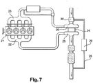
- the invention relates, with reference to the figure 7 in the appendix, the EGR loop of an internal combustion engine of a motor vehicle, comprising the engine 21, an exhaust manifold 22 for the combustion gases, a turbine 25 of a turbo-compressor 24, the recirculation loop of the gases 28 (exhaust) (EGR), with a cooler 29 and the low-pressure three-way valve disposed upstream of the compressor 26 of the turbo-compressor 24 and connected to it by its output and having two inputs for receiving fresh air and the cooled exhaust gas, a mixture whose pressure is increased in the compressor 26, and an intake manifold 23 of the engine for receiving the exhaust gas and the compressor air.
- EGR exhaust loop of an internal combustion engine of a motor vehicle
- the EGR loop aims to reduce the emission of nitrogen dioxide, by reducing the combustion temperature, by slowing down the combustion of the combustion mixture and absorbing part of the calories.
- the cooler of the EGR loop makes it possible to lower the combustion temperature at high speed (high load).
- the flow of EGR gas in the inlet channel EGR of the valve starting to decline after a rotation of the corresponding flap of about 55 ° it is in this angular position of the EGR gas shutter that the intake flap of the fresh air is started to close the fresh air intake path in the EGR valve.
- the rotation of the intake flap (5) can be carried out until it is rotated 90 °. This rotation can lead to completely close the air inlet (2).
- the pipe is closed only partially, for example by a flap whose diameter is smaller than the diameter of the pipe.
- the EGR valve 1 of Figures 1a, 1b, 1c schematically, comprises an air inlet 2, a recirculated exhaust gas inlet 3 and an air and gas outlet 4.
- the valve 1 is here a two-part valve, a flap 5 in the air inlet duct 2 and a flap 6 in the gas inlet duct 3.
- the air flap 5 is in an angular position (0 °) allowing a maximum air flow in the track 2 and the arrival flap of the gases 6, in an angular position (90 °) shutting off way 3.
- This zone III extends until the gas flap 6 reaches the angular position O ° of maximum opening of the gas inlet channel 3 and the air flap is in the angular position (90 °) total or partial closure of the air inlet 2.
- this three-way valve has the kinematics which will now be described with reference to the Figures 3 to 5 .
- the kinematics of the three-way valve 1 comprises a gear extending, here, between a DC motor 7 and two shafts 51, 61 for rotating the air flap 5 and the gas flap 6, respectively.
- the two shafts 51, 61 extend parallel to each other.
- the shaft 14 of the motor 7 is secured to a pinion 8 for driving an intermediate toothed wheel 9 bearing a peripheral toothing 10 and a central toothing 11.
- the peripheral toothing 10 of the intermediate wheel meshes with a ring gear 12 for rotating the air flap 5.
- the ring gear 12 is free to rotate relative to the axis 51 of the flap 5.
- the rotational drive this flap 5 by the ring 12 is via a drive finger 15 which is itself integral in rotation with the axis 51 of the flap 5.
- This finger 15 is disposed at rest against an adjustable stop 16 integral with the body of the valve (not shown).
- the ring 12 has an angular notch 17 adapted to allow the free rotation of the ring 12 on a defined angular sector, without driving the finger 15, that is to say the flap 5. It is when the ring 12 is driven in rotation beyond this angular sector, in one direction or the other, that the edge of the notch 17 then drives the finger 15.
- the central toothing 11 of the intermediate wheel 9 meshes with a ring gear 13 for rotating the flap of the gas 6.
- the ring gear 13 is rotationally integral with the axis 61 of the flap 6.
- the flap 6 is therefore rotated directly by the rotation of the ring 13, while the flap 5 is rotated only when the ring 12 rotates the finger 15.
- the wheel 9, by its teeth 10, 11 drives, in the opposite direction of the needles, the two toothed rings 12, 13, which are thus rotated by the same intermediate wheel 9, but via two gear teeth 10, 11.
- the gear ratio between the shaft 14 of the motor 7 and the flap of the gas 6 is here 15.67, the ratio between the shaft 14 and the air flap 5 when is driven being 6.67.
- the Figures 3, 4 , and 5 show the crowns and toothed wheels at different stages of rotation of the pinion 8.
- FIG. figure 6 An alternative embodiment of the phase shift mechanism is shown in FIG. figure 6 .
- a cross member 50 with two radial arms 52, 53 is mounted on the shaft 51 of the flap 5.
- Each of the arms 52, 53 comprises at its end a driving pin 54, 55, extending substantially parallel to the tree 51.
- the ring gear 12 In the ring gear 12 are formed two circular lights 56, 57 for driving fingers 54, 55 in circular translation.
- the fingers 54, 55 extend respectively in these two lights 56, 57.
- the angular opening of the lights must be less than 180 °. If ⁇ g is the angle of rotation of the gas flap 6, ⁇ a , the angle of rotation of the air flap 5, the relation (1) must be satisfied. ⁇ boy Wut - ⁇ at ⁇ ⁇ boy Wut ⁇ at ⁇ 180
- the circular lights 56, 57 are formed in the ring 12 relative to the toothed sector of the ring 12 taking into account the amplitude of the angular rotation of the gas flap 6 before the air flap 5 begins to rotate.
- valve that has just been described is remarkable for its uniqueness of control, at the single level of the DC motor 7, which makes it a better price and a smaller footprint.
- This control can be achieved using an H bridge, well known to those skilled in the art, with two pairs of switches in series and the component to be controlled - here the motor - connected to the two middle points of two pairs of switches, the two pairs being connected between a battery voltage and ground.
Landscapes
- Engineering & Computer Science (AREA)
- Chemical & Material Sciences (AREA)
- Combustion & Propulsion (AREA)
- Mechanical Engineering (AREA)
- General Engineering & Computer Science (AREA)
- Exhaust-Gas Circulating Devices (AREA)
- Mechanically-Actuated Valves (AREA)
- Multiple-Way Valves (AREA)
- Electrically Driven Valve-Operating Means (AREA)
Description
- L'invention concerne, en référence à la
figure 7 en annexe, la boucle EGR d'un moteur à combustion interne d'un véhicule automobile, comprenant le moteur 21, un collecteur d'échappement 22 des gaz de combustion, une turbine 25 de turbo-compresseur 24, la boucle de recirculation des gaz d'échappement (EGR) 28, avec un refroidisseur 29 et la vanne trois voies 30 basse pression disposée en amont du compresseur 26 du turbo-compresseur 24 et reliée à lui par sa sortie et comportant deux entrées pour recevoir de l'air frais et les gaz d'échappement refroidis, en un mélange dont la pression est augmentée dans le compresseur 26, et un collecteur d'admission 23 du moteur pour recevoir les gaz d'échappement et l'air du compresseur. - La boucle EGR vise à réduire l'émission de dioxyde d'azote, par diminution de la température de combustion, par ralentissement de la combustion du mélange comburant et absorption d'une partie des calories. Le refroidisseur de la boucle EGR permet de faire chuter la température de combustion à fort régime (forte charge).
- Plusieurs modes opératoires de la vanne trois voies et donc du moteur peuvent être envisagés. Deux dispositifs de réglage du débit de gaz EGR sont présentés dans le
US 2005/02 41 702 A1 et leFR 2 806 448 A1 - Ainsi, l'invention concerne un mode d'utilisation particulier de la boucle EGR ci-dessus, caractérisé par le fait que
- le débit de l'air frais dans la voie d'arrivée de l'air de la vanne EGR étant maximum,
- on ouvre progressivement la voie des gaz EGR dans la vanne et,
- avant que le débit des gaz EGR dans la vanne n'augmente plus,
- on ferme progressivement la voie d'arrivée de l'air frais pour continuer de faire croître le débit des gaz EGR, suivant une courbe monotone croissante.
- Dans le mode de mise en oeuvre selon l'invention, avec une vanne trois voies à deux volets, le débit de gaz EGR dans la voie d'entrée EGR de la vanne commençant à décliner après une rotation du volet correspondant d'environ 55°, c'est dans cette position angulaire du volet des gaz EGR qu'on commence à faire tourner le volet d'admission de l'air frais pour fermer la voie d'arrivée d'air frais dans la vanne EGR. La rotation du volet d'admission (5) peut être effectuée jusqu'à le faire tourner de 90°. Cette rotation peut conduire à obturer totalement la voie d'arrivée d'air (2). En variante, la conduite n'est obturée que partiellement, par exemple grâce à un volet dont le diamètre est inférieur au diamètre de la conduite.
- On notera que dans le moteur du document
US 2005/0193978 , la surpression définie par une vanne déterminée est toujours au niveau correspondant au fonctionnement du moteur ; si la surpression varie par cette vanne, la quantité d'air admise varie aussi. - L'invention sera mieux comprise à l'aide de la description suivante du mode d'utilisation de la vanne trois voies et donc de la boucle EGR, ainsi que de la vanne trois voies elle-même, en référence au dessin en annexe, sur lequel
- les
figures 1a, 1b, 1c, 1d illustrent les quatre modes d'utilisation de la vanne trois voies de la boucle EGR dont l'utilisation particulière est revendiquée par la présente demande ; - les
figures 2a, 2b, 2c représentent les courbes de débit d'air (1a), de débit naturel de gaz d'échappement EGR (dgn) et de débit, forcé selon l'invention, de gaz d'échappement EGR (dgf), en fonction des positions angulaires (α) des volets correspondants ; - la
figure 3 est une vue en perspective de la cinématique de la vanne trois voies à deux volets, volet d'air ouvert et volet des gaz fermé ; - la
figure 4 est une vue de la vanne de lafigure 3 , volet des gaz en position d'ouverture partielle ; - la
figure 5 est une vue de la vanne de lafigure 3 , volet des gaz ouvert et volet d'air fermé ; - la
figure 6 est une vue partielle en perspective de la cinématique d'une vanne trois voies selon une variante du mécanisme de déphasage temporel de la fermeture du volet d'air par rapport à l'ouverture du volet des gaz et - la
figure 7 représente de façon simplifiée, la boucle EGR utilisée selon l'invention. - La vanne EGR 1 des
figures 1a, 1b, 1c , schématiquement, comporte une entrée d'air 2, une entrée de gaz d'échappement recirculés 3 et une sortie d'air et de gaz 4. - La vanne 1 est ici une vanne à deux volets, un volet 5 dans la voie d'entrée d'air 2 et un volet 6 dans la voie d'entrée de gaz 3.
- Tout d'abord, le volet d'air 5 est dans une position angulaire (0°) permettant un débit d'air maximal dans la voie 2 et le volet d'arrivée des gaz 6, dans une position angulaire (90°) obturant la voie 3.
- Puis, sans que le volet d'air 5 ne pivote, le volet d'arrivée des gaz 6 - commence à pivoter pour ouvrir progressivement la voie 3 aux gaz d'échappement EGR (
figure 1a ). Il s'agit de la zone I des courbes 2. Puis, le volet d'air 5 restant dans la même position d'ouverture maximale de l'entrée d'air 3, le volet des gaz 6 pivote pour considérablement ouvrir la voie des gaz 6 (figure 1b ). Il s'agit de la zone II des courbes 2. Dans une certaine position angulaire du volet des gaz 6, ici de 35°, c'est-à-dire après une rotation de 55°, le débit des gaz dans la voie 3 n'augmente pratiquement plus et, tout en continuant de faire pivoter le volet des gaz 6, on commence alors à faire pivoter le volet d'air 5 pour fermer la voie d'arrivée d'air 2, avec un déphasage temporel correspondant, et, ainsi, forcer le moteur à aspirer d'avantage de gaz EGR (figure 1c ). - On entre dans la zone III des courbes 2, la courbe de débit des gaz d'échappement s'infléchissant pour continuer de monter.
- Cette zone III s'étend jusqu'à ce que le volet des gaz 6 atteigne la position angulaire O° d'ouverture maximale de la voie d'entrée de gaz 3 et que le volet d'air se trouve dans la position angulaire (90°) d'obturation totale ou partielle de la voie d'entrée d'air 2.
- Pour la mise en oeuvre de l'alimentation de la vanne EGR trois voies 1, telle que définie ci-dessus, cette vanne trois voies présente la cinématique qui va maintenant être décrite en référence aux
figures 3 à 5 . - La cinématique de la vanne trois voies 1 comporte un engrenage s'étendant, ici, entre un moteur à courant continu 7 et deux arbres 51, 61 d'entraînement en rotation du volet d'air 5 et du volet des gaz 6, respectivement. Les deux arbres 51, 61 s'étendent parallèlement l'un à l'autre.
- De l'arbre 14 du moteur 7 est solidaire un pignon 8 d'entraînement d'une roue dentée intermédiaire 9 portant une denture périphérique 10 et une denture centrale 11.
- La denture périphérique 10 de la roue intermédiaire engrène avec une couronne dentée 12 d'entraînement en rotation du volet d'air 5. La couronne dentée 12 est libre en rotation par rapport à l'axe 51 du volet 5. L'entraînement en rotation de ce volet 5 par la couronne 12 se fait par l'intermédiaire d'un doigt d'entraînement 15 qui est, lui, solidaire en rotation de l'axe 51 du volet 5. Ce doigt 15 est disposé au repos contre une butée réglable 16 solidaire du corps de la vanne (non représenté). La couronne 12 comporte une échancrure angulaire 17 adaptée à permettre la rotation libre de la couronne 12 sur un secteur angulaire défini, sans entraîner le doigt 15, c'est-à-dire le volet 5. C'est lorsque la couronne 12 est entraînée en rotation au-delà de ce secteur angulaire, dans un sens ou dans l'autre, que le bord de l'échancrure 17 entraîne alors le doigt 15.
- La denture centrale 11 de la roue intermédiaire 9 engrène quant à elle avec une couronne dentée 13 d'entraînement en rotation du volet des gaz 6. La couronne dentée 13 est solidaire en rotation de l'axe 61 du volet 6.
- Le volet 6 est donc entraîné en rotation directement par la rotation de la couronne 13, tandis que le volet 5 est entraîné en rotation seulement lorsque la couronne 12 entraîne en rotation le doigt 15.
- Dans l'exemple considéré, le moteur 7, par son pignon 8, entraîné en rotation dans le sens contraire des aiguilles d'une montre, entraîne la roue intermédiaire 9 en rotation dans le sens des aiguilles d'une montre. A son tour, la roue 9, par ses dentures 10, 11 entraîne, dans le sens contraire des aiguilles d'une montre, les deux couronnes dentées 12, 13, qui sont donc entraînées en rotation par la même roue intermédiaire 9, mais via deux dentures différentes 10, 11. Le rapport d'engrenage entre l'arbre 14 du moteur 7 et le volet des gaz 6 est ici de 15,67, le rapport entre l'arbre 14 et le volet d'air 5 lorsqu'il est entraîné étant de 6,67.
- Le mécanisme de déphasage de la fermeture du volet d'air 5 va maintenant être décrit.
- Les
figures 3, 4 , et5 montrent les couronnes et roues dentées à différentes étapes de la rotation du pignon 8. - De la
figure 3 à lafigure 4 , les couronnes 12 et 13 sont entraînées dans le sens contraire des aiguilles d'une montre de sorte provoquant l'ouverture du volet 6 tandis que le volet 5 reste immobile et ce grâce à l'échancrure angulaire 17. Sur la position de lafigure 4 , l'un des bords de cette échancrure 17 vient en contact avec le doigt 15. - La rotation de la couronne 12 se poursuit alors en direction de la position représentée
figure 5 , le doigt 15 (et par conséquent le volet 5) étant alors entraîné en rotation. Le volet 5 se ferme donc avec un déphasage temporel permis par l'échancrure 17. - Une variante de réalisation du mécanisme de déphasage est représentée à la
figure 6 . Selon cette variante, une traverse 50 à deux bras radiaux 52, 53 est montée sur l'arbre 51 du volet 5. Chacun des bras 52, 53 comporte à son extrémité un doigt d'entraînement 54, 55, s'étendant sensiblement parallèlement à l'arbre 51. - Dans la couronne dentée 12 sont ménagées deux lumières circulaires 56, 57 d'entraînement des doigts 54, 55 en translation circulaire. Les doigts 54, 55 s'étendent respectivement dans ces deux lumières 56, 57.
- Tant que les doigts 54, 55 ne sont pas en appui contre l'un des fonds 58 des lumières 56, 57, l'arbre 51 et le volet d'air 5 ne peuvent pas être entraînés en rotation. Dès que les doigts 54, 55 viennent en butée contre les fonds respectifs des deux lumières 56, 57, la couronne dentée 12 les entraîne avec elle, ce qui provoque la mise en rotation du volet 5.
- Pour assurer le fonctionnement correct de la vanne trois voies, il faut que l'ouverture angulaire des lumières soit inférieure à 180°. Si αg est l'angle de rotation du volet des gaz 6, αa, l'angle de rotation du volet d'air 5, la relation (1) doit être satisfaite

- Si on considère αg = 90° (
figure 2b ), alors l'angle de rotation αa du volet d'air 5 doit satisfaire la relation (2)
- Le rapport d'engrenage


- Dans l'exemple évoqué ci-dessus, on a considéré

- Les lumières circulaires 56, 57 sont ménagées dans la couronne 12 par rapport au secteur denté de la couronne 12 en tenant compte de l'amplitude de la rotation angulaire du volet des gaz 6 avant que le volet d'air 5 ne commence sa rotation.
- La vanne qui vient d'être décrite est remarquable par son unicité de commande, au seul niveau du moteur à courant continu 7, ce qui la rend d'un meilleur prix et d'un encombrement réduit.
- Cette commande peut être réalisée à l'aide d'un pont en H, bien connu de l'homme du métier, avec deux paires d'interrupteurs en série et le composant à commander - ici le moteur - relié aux deux points milieux des deux paires d'interrupteurs, les deux paires étant branchées entre une tension batterie et la masse.
Claims (4)
- Mode d'utilisation d'une boucle EGR d'un moteur à combustion interne d'un véhicule automobile, comprenant le moteur (21), un collecteur (22) d'échappement des gaz de combustion, une turbine (25) de turbo-compresseur (24), la boucle (28) de recirculation des gaz d'échappement (EGR), avec un refroidisseur (29) et une vanne trois voies basse pression (30) disposée en amont du compresseur (26) du turbo-compresseur et reliée à lui par sa sortie et comportant deux entrées pour recevoir de l'air frais et les gaz d'échappement refroidis en un mélange dont la pression est augmentée dans le compresseur, la vanne trois voies (1) ayant deux volets (5, 6) pour les deux voies air frais (2) et gaz EGR (3) respectivement,
et un collecteur d'admission (23) du moteur pour recevoir les gaz d'échappement et l'air du compresseur (26), caractérisé par le fait que- le débit de l'air frais dans la voie d'arrivée de l'air (2) de la vanne EGR (1) étant maximum,- on ouvre progressivement la voie des gaz EGR (3) dans la vanne et,- avant que le débit des gaz EGR dans la vanne n'augmente plus,- on ferme progressivement la voie (2) d'arrivée de l'air frais pour continuer de faire croître le débit des gaz EGR, suivant une courbe monotone croissante,le débit de gaz EGR dans la voie d'entrée EGR (3) de la vanne (1) commençant à décliner après une rotation du volet correspondant (6) d'environ 55°, c'est de cette position angulaire du volet des gaz EGR (6) qu'on commence à faire tourner le volet d'admission de l'air frais (5) pour fermer la voie d'arrivée d'air frais (2) dans la vanne EGR. - Mode d'utilisation selon la revendication 1, caractérisé en ce que la rotation du volet d'admission (5) est effectuée jusqu'à le faire tourner de 90°.
- Mode d'utilisation selon l'une des revendications 1 ou 2, caractérisé en ce que la rotation du volet d'admission (5) est effectuée jusqu'à obturer totalement la voie d'arrivée d'air (2).
- Mode d'utilisation selon l'une des revendications 1 ou 2, caractérisé en ce que la rotation du volet d'admission (5) est effectuée jusqu'à obturer partiellement la voie d'arrivée d'air (2).
Applications Claiming Priority (2)
| Application Number | Priority Date | Filing Date | Title |
|---|---|---|---|
| FR0800026A FR2926114B1 (fr) | 2008-01-03 | 2008-01-03 | Boucle egr d'un moteur a combustion interne d'un vehicule automobile |
| PCT/FR2008/001780 WO2009106726A1 (fr) | 2008-01-03 | 2008-12-18 | Boucle egr d'un moteur a combustion interne d'un vehicule automobile |
Publications (2)
| Publication Number | Publication Date |
|---|---|
| EP2240679A1 EP2240679A1 (fr) | 2010-10-20 |
| EP2240679B1 true EP2240679B1 (fr) | 2018-03-14 |
Family
ID=39705176
Family Applications (2)
| Application Number | Title | Priority Date | Filing Date |
|---|---|---|---|
| EP08872752.4A Active EP2240679B1 (fr) | 2008-01-03 | 2008-12-18 | Boucle egr d'un moteur a combustion interne d'un vehicule automobile |
| EP20080873011 Not-in-force EP2245349B1 (fr) | 2008-01-03 | 2008-12-18 | Vanne trois voies à deux volets |
Family Applications After (1)
| Application Number | Title | Priority Date | Filing Date |
|---|---|---|---|
| EP20080873011 Not-in-force EP2245349B1 (fr) | 2008-01-03 | 2008-12-18 | Vanne trois voies à deux volets |
Country Status (8)
| Country | Link |
|---|---|
| US (2) | US8381520B2 (fr) |
| EP (2) | EP2240679B1 (fr) |
| JP (2) | JP2011508850A (fr) |
| KR (3) | KR20100107494A (fr) |
| ES (1) | ES2458316T3 (fr) |
| FR (1) | FR2926114B1 (fr) |
| PL (1) | PL2245349T3 (fr) |
| WO (2) | WO2009106726A1 (fr) |
Families Citing this family (35)
| Publication number | Priority date | Publication date | Assignee | Title |
|---|---|---|---|---|
| FR2926113A1 (fr) * | 2008-01-03 | 2009-07-10 | Valeo Sys Controle Moteur Sas | Boucle egr d'un moteur a combustion interne d'un vehicule automobile |
| FR2926114B1 (fr) | 2008-01-03 | 2012-12-14 | Valeo Sys Controle Moteur Sas | Boucle egr d'un moteur a combustion interne d'un vehicule automobile |
| JP4730447B2 (ja) * | 2009-02-18 | 2011-07-20 | 株式会社デンソー | 低圧egr装置 |
| JP4935866B2 (ja) * | 2009-07-31 | 2012-05-23 | 株式会社デンソー | 低圧egr装置 |
| ITBO20090702A1 (it) * | 2009-10-28 | 2011-04-28 | Magneti Marelli Spa | Dispositivo miscelatore per un sistema egr di bassa pressione di un motore a combustione interna |
| EP2317109A1 (fr) * | 2009-11-03 | 2011-05-04 | Cooper-Standard Automotive (Deutschland) GmbH | Système de recircualtion des gaz d'échappement et procédé de fonctionnement d'un système de recirculation des gaz d'échappement |
| DE102009056251B4 (de) * | 2009-12-01 | 2014-01-09 | Pierburg Gmbh | Ventilvorrichtung für eine Verbrennungskraftmaschine |
| FR2954407B1 (fr) * | 2009-12-22 | 2018-11-23 | Valeo Systemes De Controle Moteur | Procede de commande d'un circuit egr d'un moteur de vehicule automobile, vanne pour la mise en oeuvre du procede et moteur avec la vanne. |
| DE112010004964T5 (de) * | 2009-12-22 | 2012-11-22 | Borgwarner Inc. | Verbrennungsmotor |
| FR2954408B1 (fr) * | 2009-12-22 | 2015-12-25 | Valeo Sys Controle Moteur Sas | Procede de commande d'un circuit egr d'un moteur de vehicule automobile. |
| DE102010052563A1 (de) * | 2010-11-25 | 2012-05-31 | Volkswagen Ag | Einrichtung zur Beeinflussung von Gas-Volumenströmen, Verfahren zur Steuerung und/oder Regelung eines Abgasstromes oder eines Ladeluftstromes, Abgasstrang und Kraftfahrzeug |
| JP5287953B2 (ja) * | 2011-04-27 | 2013-09-11 | 株式会社デンソー | 低圧egr装置 |
| FR2979409B1 (fr) * | 2011-08-23 | 2013-08-23 | Valeo Sys Controle Moteur Sas | Vanne trois-voies a deux obturateurs et detection de course, notamment pour circuit d'admission de moteur d'automobile |
| FR2979410B1 (fr) | 2011-08-23 | 2013-08-23 | Valeo Sys Controle Moteur Sas | Vanne, notamment pour circuit d'admission de moteur d'automobile, comportant un moyen d'entrainement en retour d'un volet obturateur en cas de defaillance du moyen de rappel |
| FR2984962B1 (fr) * | 2011-12-21 | 2013-11-29 | Valeo Sys Controle Moteur Sas | Dispositif de dosage a deux voies securise pour moteur d'automobile |
| FR2984960B1 (fr) * | 2011-12-21 | 2013-12-20 | Valeo Sys Controle Moteur Sas | Doseur deux voies avec dosage sur chaque voie |
| DE102012205691A1 (de) * | 2012-04-05 | 2013-10-10 | Continental Automotive Gmbh | Mischventil einer Brennkraftmaschine eines Kraftfahrzeuges |
| US8869835B1 (en) * | 2012-04-17 | 2014-10-28 | Burner Systems International, Inc. | Dual valve |
| EP2653709A1 (fr) * | 2012-04-18 | 2013-10-23 | Continental Automotive GmbH | Vanne mélangeuse d'un moteur à combustion d'un véhicule automobile |
| DE102012207122A1 (de) * | 2012-04-27 | 2013-10-31 | Continental Automotive Gmbh | Mischventil einer Brennkraftmaschine |
| FR2990726B1 (fr) * | 2012-05-15 | 2015-08-21 | Valeo Sys Controle Moteur Sas | Doseur deux voies et applications dudit doseur |
| FR3004502B1 (fr) * | 2013-04-12 | 2016-01-01 | Valeo Sys Controle Moteur Sas | Vanne, notamment de controle moteur, dotee d’un volet de dosage et d’un volet d’aiguillage |
| EP2843223B1 (fr) * | 2013-09-02 | 2017-02-01 | Continental Automotive GmbH | Vanne mélangeuse d'un moteur à combustion interne |
| KR101338272B1 (ko) | 2013-10-23 | 2013-12-09 | 캄텍주식회사 | 차량용 egr 밸브 |
| EP2884086B1 (fr) * | 2013-12-11 | 2017-12-20 | Borgwarner Inc. | Actionneur avec retour de soupape |
| KR101444193B1 (ko) * | 2014-03-05 | 2014-09-26 | 주식회사 디에이치콘트롤스 | 3방향 제어 밸브 |
| JP6223273B2 (ja) * | 2014-04-30 | 2017-11-01 | 日本電産サンキョー株式会社 | ダンパ装置 |
| DE102015106888B4 (de) | 2014-09-30 | 2022-01-27 | Hyundai Motor Company | Ansaugluftsteuerungsvorrichtung eines Verbrennungsmotors |
| GB2535995A (en) * | 2015-02-27 | 2016-09-07 | Ford Global Tech Llc | A geared valve system |
| JP6571395B2 (ja) * | 2015-05-29 | 2019-09-04 | 日本電産サンキョー株式会社 | ダンパ装置 |
| KR102107736B1 (ko) * | 2015-08-03 | 2020-05-07 | 주식회사 엘지화학 | 플렉시블 플라스틱 필름용 코팅 조성물 |
| JP6648740B2 (ja) * | 2016-11-29 | 2020-02-14 | 株式会社デンソー | 弁装置、及び、弁装置の製造方法 |
| US10683812B2 (en) * | 2018-08-17 | 2020-06-16 | Raytheon Technologies Corporation | Dual valve system with mechanical linkage |
| EP3708821A1 (fr) * | 2019-03-15 | 2020-09-16 | Borgwarner Inc. | Compresseur pour charger un moteur à combustion |
| US11391251B2 (en) | 2019-04-08 | 2022-07-19 | Spi.Systems Corporation | Systems and methods for treated exhaust gas recirculation in internal combustion engines |
Family Cites Families (25)
| Publication number | Priority date | Publication date | Assignee | Title |
|---|---|---|---|---|
| US3572656A (en) * | 1968-08-28 | 1971-03-30 | Takakazu Oshima | Valve mechanism in carburetor for car |
| US4295491A (en) * | 1980-05-15 | 1981-10-20 | Fox Valley Process Systems & Supply, Inc. | Double angled-disc diverter valve or the like |
| US4749004A (en) * | 1987-05-06 | 1988-06-07 | The Boeing Company | Airflow control valve having single inlet and multiple outlets |
| US4924840A (en) * | 1988-10-05 | 1990-05-15 | Ford Motor Company | Fast response exhaust gas recirculation (EGR) system |
| JPH06249044A (ja) * | 1993-02-25 | 1994-09-06 | Yamaha Motor Co Ltd | エンジン制御装置 |
| JPH07332119A (ja) * | 1994-06-10 | 1995-12-22 | Nippondenso Co Ltd | 可変気筒装置 |
| US5427141A (en) * | 1994-09-19 | 1995-06-27 | Fuji Oozx Inc. | Pressure fluid control valve device |
| GB2329001B (en) * | 1997-09-04 | 2001-09-05 | Gen Motors Corp | Exhaust gas recirculation valve |
| SE521713C2 (sv) * | 1998-11-09 | 2003-12-02 | Stt Emtec Ab | Förfarande och anordning för ett EGR-system, samt dylik ventil |
| LU90480B1 (en) * | 1999-11-29 | 2001-05-30 | Delphi Tech Inc | Exhaust gas re-circulation device for an internal combustion engine |
| FR2806448B1 (fr) * | 2000-03-16 | 2003-01-17 | Coutier Moulage Gen Ind | Dispositif d'obturation et de regulation du debit de gaz d'echappement dans une ligne de recyclage de gaz d'echappement connectee a une ligne d'admission d'air d'un moteur a combustion interne |
| JP4380072B2 (ja) * | 2001-03-09 | 2009-12-09 | 株式会社デンソー | Egr弁一体型電子ベンチュリ |
| JP3885569B2 (ja) * | 2001-11-29 | 2007-02-21 | いすゞ自動車株式会社 | 内燃機関のegr制御装置 |
| JP2004132290A (ja) | 2002-10-11 | 2004-04-30 | Mikuni Corp | 多連スロットル装置 |
| JP2005158008A (ja) * | 2003-11-06 | 2005-06-16 | Matsushita Electric Ind Co Ltd | タッチパネルおよびこれを用いたタッチパネル付き液晶表示装置 |
| JP2005248748A (ja) | 2004-03-02 | 2005-09-15 | Isuzu Motors Ltd | ディーゼルエンジン |
| SE526824C2 (sv) * | 2004-03-26 | 2005-11-08 | Stt Emtec Ab | Ventil |
| DE102004044894A1 (de) | 2004-09-14 | 2006-03-30 | Volkswagen Ag | Mischeinrichtung und Abgasrückführeinrichtung mit einer Mischeinrichtung |
| FR2879712B1 (fr) | 2004-12-17 | 2007-02-23 | Renault Sas | Connecteur fluidique pour vehicule automobile a liaison arbre-volet demontable |
| DE102005048911A1 (de) | 2005-10-10 | 2007-04-12 | Behr Gmbh & Co. Kg | Anordnung zur Rückführung und Kühlung von Abgas einer Brennkraftmaschine |
| WO2007089771A2 (fr) * | 2006-01-31 | 2007-08-09 | Borgwarner Inc. | Soupape de recirculation des gaz d'échappement et papillon des gaz intégrés |
| FR2900455B1 (fr) * | 2006-04-26 | 2008-07-04 | Valeo Sys Controle Moteur Sas | Vanne a deux papillons actionnes par un moteur commun |
| FR2926114B1 (fr) | 2008-01-03 | 2012-12-14 | Valeo Sys Controle Moteur Sas | Boucle egr d'un moteur a combustion interne d'un vehicule automobile |
| FR2926113A1 (fr) | 2008-01-03 | 2009-07-10 | Valeo Sys Controle Moteur Sas | Boucle egr d'un moteur a combustion interne d'un vehicule automobile |
| US7987837B2 (en) * | 2010-02-16 | 2011-08-02 | Ford Global Technologies, Llc | Exhaust treatment system for internal combustion engine |
-
2008
- 2008-01-03 FR FR0800026A patent/FR2926114B1/fr active Active
- 2008-12-18 US US12/811,114 patent/US8381520B2/en active Active
- 2008-12-18 KR KR1020107017253A patent/KR20100107494A/ko not_active Ceased
- 2008-12-18 JP JP2010541079A patent/JP2011508850A/ja active Pending
- 2008-12-18 US US12/811,116 patent/US8561645B2/en not_active Expired - Fee Related
- 2008-12-18 ES ES08873011T patent/ES2458316T3/es active Active
- 2008-12-18 KR KR1020107017281A patent/KR101646278B1/ko active Active
- 2008-12-18 PL PL08873011T patent/PL2245349T3/pl unknown
- 2008-12-18 EP EP08872752.4A patent/EP2240679B1/fr active Active
- 2008-12-18 WO PCT/FR2008/001780 patent/WO2009106726A1/fr not_active Ceased
- 2008-12-18 KR KR20157004865A patent/KR20150040311A/ko not_active Ceased
- 2008-12-18 EP EP20080873011 patent/EP2245349B1/fr not_active Not-in-force
- 2008-12-18 WO PCT/FR2008/001781 patent/WO2009106727A1/fr not_active Ceased
- 2008-12-18 JP JP2010541080A patent/JP2011508861A/ja active Pending
Also Published As
| Publication number | Publication date |
|---|---|
| WO2009106726A1 (fr) | 2009-09-03 |
| KR20100107494A (ko) | 2010-10-05 |
| US8381520B2 (en) | 2013-02-26 |
| KR20100116181A (ko) | 2010-10-29 |
| JP2011508861A (ja) | 2011-03-17 |
| EP2240679A1 (fr) | 2010-10-20 |
| US8561645B2 (en) | 2013-10-22 |
| FR2926114A1 (fr) | 2009-07-10 |
| ES2458316T3 (es) | 2014-04-30 |
| KR20150040311A (ko) | 2015-04-14 |
| EP2245349A1 (fr) | 2010-11-03 |
| FR2926114B1 (fr) | 2012-12-14 |
| PL2245349T3 (pl) | 2014-06-30 |
| EP2245349B1 (fr) | 2014-01-15 |
| US20110048004A1 (en) | 2011-03-03 |
| WO2009106727A1 (fr) | 2009-09-03 |
| US20110114211A1 (en) | 2011-05-19 |
| KR101646278B1 (ko) | 2016-08-05 |
| JP2011508850A (ja) | 2011-03-17 |
Similar Documents
| Publication | Publication Date | Title |
|---|---|---|
| EP2240679B1 (fr) | Boucle egr d'un moteur a combustion interne d'un vehicule automobile | |
| EP2562450B1 (fr) | Vanne trois-voies | |
| EP2562451B1 (fr) | Vanne trois-voies | |
| EP2516835B1 (fr) | Procede de commande d'un circuit egr d'un moteur de vehicule automobile. | |
| EP2516836B1 (fr) | Procede de commande d'un circuit egr d'un moteur de vehicule automobile et vanne pour la mise en oeuvre | |
| EP2795079B1 (fr) | Dispositif de dosage a deux voies securisé pour moteur d'automobile | |
| FR2571112A1 (fr) | Transmission comportant des arbres de sortie doubles animes d'un mouvement de rotation en sens contraire | |
| EP2932140B1 (fr) | Vanne a deux volets places en serie et actionnes par un moteur | |
| FR2926126A1 (fr) | Vanne trois voies | |
| WO2008078020A1 (fr) | Moteur a combustion interne suralimente comprenant des collecteurs d'echappement a volume variable | |
| FR2926125A1 (fr) | Vanne trois voies a deux volets | |
| EP2783097B1 (fr) | Vanne de controle pour systeme de recirculation des gaz d'echappement d'un moteur a combustion interne | |
| EP2795081B1 (fr) | Doseur deux voies avec un moteur unique agissant dans un seul sens | |
| FR2860834A1 (fr) | Moteur a combustion interne suralimente avec un dispositif de suralimentation muni d'un circuit de decharge des gaz d'echappement et procede de gestion des gaz d'echappement d'un tel moteur | |
| FR2752880A1 (fr) | Dispositif de suralimentation pour moteur a combustion interne | |
| EP3751112B1 (fr) | Procédé de pilotage d'un ensemble comportant un turbocompresseur et des moyens complémentaires d' entraînement | |
| FR2944322A1 (fr) | Dispositif de suralimentation de l'air d'admission d'un moteur a combustion interne avec un etage d'entrainement d'un turbocompresseur comportant au moins deux turbines | |
| FR2947867A3 (fr) | Moteur a combustion interne pour vehicule automobile suralimente par deux turbocompresseurs | |
| FR2879673A1 (fr) | Moteur a combustion interne comprenant un systeme d'obturation de conduit d'admission par volets a positions discretes et vehicule automobile comprenant un tel moteur | |
| BE505563A (fr) | ||
| EP2027379A1 (fr) | Procede et dispositif de regulation d'un flux de gaz de recirculation circulant dans une ligne de recirculation d'un moteur a combustion interne | |
| CH359566A (fr) | Installation motrice comprenant un moteur à combustion interne | |
| FR2905980A1 (fr) | "groupe motopropulseur, en particulier pour vehicule automobile, ainsi que circuit et procede de suralimentation de son moteur" | |
| FR3055026A1 (fr) | Commande de by-pass double clapet | |
| FR3045768A1 (fr) | Vanne de controle d'un debit de fluide |
Legal Events
| Date | Code | Title | Description |
|---|---|---|---|
| PUAI | Public reference made under article 153(3) epc to a published international application that has entered the european phase |
Free format text: ORIGINAL CODE: 0009012 |
|
| 17P | Request for examination filed |
Effective date: 20100730 |
|
| AK | Designated contracting states |
Kind code of ref document: A1 Designated state(s): AT BE BG CH CY CZ DE DK EE ES FI FR GB GR HR HU IE IS IT LI LT LU LV MC MT NL NO PL PT RO SE SI SK TR |
|
| AX | Request for extension of the european patent |
Extension state: AL BA MK RS |
|
| DAX | Request for extension of the european patent (deleted) | ||
| RIN1 | Information on inventor provided before grant (corrected) |
Inventor name: LEROUX, SAMUEL Inventor name: ALBERT, LAURENT Inventor name: ADENOT, SEBASTIEN |
|
| 17Q | First examination report despatched |
Effective date: 20131129 |
|
| REG | Reference to a national code |
Ref country code: DE Ref legal event code: R079 Ref document number: 602008054464 Country of ref document: DE Free format text: PREVIOUS MAIN CLASS: F02M0025070000 Ipc: F02M0026520000 |
|
| RIC1 | Information provided on ipc code assigned before grant |
Ipc: F02M 26/52 20160101AFI20170704BHEP |
|
| GRAP | Despatch of communication of intention to grant a patent |
Free format text: ORIGINAL CODE: EPIDOSNIGR1 |
|
| INTG | Intention to grant announced |
Effective date: 20171010 |
|
| GRAS | Grant fee paid |
Free format text: ORIGINAL CODE: EPIDOSNIGR3 |
|
| GRAA | (expected) grant |
Free format text: ORIGINAL CODE: 0009210 |
|
| AK | Designated contracting states |
Kind code of ref document: B1 Designated state(s): AT BE BG CH CY CZ DE DK EE ES FI FR GB GR HR HU IE IS IT LI LT LU LV MC MT NL NO PL PT RO SE SI SK TR |
|
| REG | Reference to a national code |
Ref country code: GB Ref legal event code: FG4D Free format text: NOT ENGLISH |
|
| REG | Reference to a national code |
Ref country code: CH Ref legal event code: EP Ref country code: AT Ref legal event code: REF Ref document number: 979136 Country of ref document: AT Kind code of ref document: T Effective date: 20180315 |
|
| REG | Reference to a national code |
Ref country code: IE Ref legal event code: FG4D Free format text: LANGUAGE OF EP DOCUMENT: FRENCH |
|
| REG | Reference to a national code |
Ref country code: DE Ref legal event code: R096 Ref document number: 602008054464 Country of ref document: DE |
|
| REG | Reference to a national code |
Ref country code: NL Ref legal event code: MP Effective date: 20180314 |
|
| REG | Reference to a national code |
Ref country code: LT Ref legal event code: MG4D |
|
| PG25 | Lapsed in a contracting state [announced via postgrant information from national office to epo] |
Ref country code: ES Free format text: LAPSE BECAUSE OF FAILURE TO SUBMIT A TRANSLATION OF THE DESCRIPTION OR TO PAY THE FEE WITHIN THE PRESCRIBED TIME-LIMIT Effective date: 20180314 Ref country code: LT Free format text: LAPSE BECAUSE OF FAILURE TO SUBMIT A TRANSLATION OF THE DESCRIPTION OR TO PAY THE FEE WITHIN THE PRESCRIBED TIME-LIMIT Effective date: 20180314 Ref country code: NO Free format text: LAPSE BECAUSE OF FAILURE TO SUBMIT A TRANSLATION OF THE DESCRIPTION OR TO PAY THE FEE WITHIN THE PRESCRIBED TIME-LIMIT Effective date: 20180614 Ref country code: CY Free format text: LAPSE BECAUSE OF FAILURE TO SUBMIT A TRANSLATION OF THE DESCRIPTION OR TO PAY THE FEE WITHIN THE PRESCRIBED TIME-LIMIT Effective date: 20180314 Ref country code: HR Free format text: LAPSE BECAUSE OF FAILURE TO SUBMIT A TRANSLATION OF THE DESCRIPTION OR TO PAY THE FEE WITHIN THE PRESCRIBED TIME-LIMIT Effective date: 20180314 Ref country code: FI Free format text: LAPSE BECAUSE OF FAILURE TO SUBMIT A TRANSLATION OF THE DESCRIPTION OR TO PAY THE FEE WITHIN THE PRESCRIBED TIME-LIMIT Effective date: 20180314 |
|
| REG | Reference to a national code |
Ref country code: AT Ref legal event code: MK05 Ref document number: 979136 Country of ref document: AT Kind code of ref document: T Effective date: 20180314 |
|
| PG25 | Lapsed in a contracting state [announced via postgrant information from national office to epo] |
Ref country code: GR Free format text: LAPSE BECAUSE OF FAILURE TO SUBMIT A TRANSLATION OF THE DESCRIPTION OR TO PAY THE FEE WITHIN THE PRESCRIBED TIME-LIMIT Effective date: 20180615 Ref country code: BG Free format text: LAPSE BECAUSE OF FAILURE TO SUBMIT A TRANSLATION OF THE DESCRIPTION OR TO PAY THE FEE WITHIN THE PRESCRIBED TIME-LIMIT Effective date: 20180614 Ref country code: LV Free format text: LAPSE BECAUSE OF FAILURE TO SUBMIT A TRANSLATION OF THE DESCRIPTION OR TO PAY THE FEE WITHIN THE PRESCRIBED TIME-LIMIT Effective date: 20180314 Ref country code: SE Free format text: LAPSE BECAUSE OF FAILURE TO SUBMIT A TRANSLATION OF THE DESCRIPTION OR TO PAY THE FEE WITHIN THE PRESCRIBED TIME-LIMIT Effective date: 20180314 |
|
| PG25 | Lapsed in a contracting state [announced via postgrant information from national office to epo] |
Ref country code: MT Free format text: LAPSE BECAUSE OF FAILURE TO SUBMIT A TRANSLATION OF THE DESCRIPTION OR TO PAY THE FEE WITHIN THE PRESCRIBED TIME-LIMIT Effective date: 20180314 |
|
| PG25 | Lapsed in a contracting state [announced via postgrant information from national office to epo] |
Ref country code: RO Free format text: LAPSE BECAUSE OF FAILURE TO SUBMIT A TRANSLATION OF THE DESCRIPTION OR TO PAY THE FEE WITHIN THE PRESCRIBED TIME-LIMIT Effective date: 20180314 Ref country code: PL Free format text: LAPSE BECAUSE OF FAILURE TO SUBMIT A TRANSLATION OF THE DESCRIPTION OR TO PAY THE FEE WITHIN THE PRESCRIBED TIME-LIMIT Effective date: 20180314 Ref country code: NL Free format text: LAPSE BECAUSE OF FAILURE TO SUBMIT A TRANSLATION OF THE DESCRIPTION OR TO PAY THE FEE WITHIN THE PRESCRIBED TIME-LIMIT Effective date: 20180314 Ref country code: EE Free format text: LAPSE BECAUSE OF FAILURE TO SUBMIT A TRANSLATION OF THE DESCRIPTION OR TO PAY THE FEE WITHIN THE PRESCRIBED TIME-LIMIT Effective date: 20180314 Ref country code: IT Free format text: LAPSE BECAUSE OF FAILURE TO SUBMIT A TRANSLATION OF THE DESCRIPTION OR TO PAY THE FEE WITHIN THE PRESCRIBED TIME-LIMIT Effective date: 20180314 |
|
| PG25 | Lapsed in a contracting state [announced via postgrant information from national office to epo] |
Ref country code: AT Free format text: LAPSE BECAUSE OF FAILURE TO SUBMIT A TRANSLATION OF THE DESCRIPTION OR TO PAY THE FEE WITHIN THE PRESCRIBED TIME-LIMIT Effective date: 20180314 Ref country code: SK Free format text: LAPSE BECAUSE OF FAILURE TO SUBMIT A TRANSLATION OF THE DESCRIPTION OR TO PAY THE FEE WITHIN THE PRESCRIBED TIME-LIMIT Effective date: 20180314 Ref country code: CZ Free format text: LAPSE BECAUSE OF FAILURE TO SUBMIT A TRANSLATION OF THE DESCRIPTION OR TO PAY THE FEE WITHIN THE PRESCRIBED TIME-LIMIT Effective date: 20180314 |
|
| REG | Reference to a national code |
Ref country code: DE Ref legal event code: R097 Ref document number: 602008054464 Country of ref document: DE |
|
| PG25 | Lapsed in a contracting state [announced via postgrant information from national office to epo] |
Ref country code: PT Free format text: LAPSE BECAUSE OF FAILURE TO SUBMIT A TRANSLATION OF THE DESCRIPTION OR TO PAY THE FEE WITHIN THE PRESCRIBED TIME-LIMIT Effective date: 20180716 |
|
| PLBE | No opposition filed within time limit |
Free format text: ORIGINAL CODE: 0009261 |
|
| STAA | Information on the status of an ep patent application or granted ep patent |
Free format text: STATUS: NO OPPOSITION FILED WITHIN TIME LIMIT |
|
| PG25 | Lapsed in a contracting state [announced via postgrant information from national office to epo] |
Ref country code: DK Free format text: LAPSE BECAUSE OF FAILURE TO SUBMIT A TRANSLATION OF THE DESCRIPTION OR TO PAY THE FEE WITHIN THE PRESCRIBED TIME-LIMIT Effective date: 20180314 |
|
| 26N | No opposition filed |
Effective date: 20181217 |
|
| PG25 | Lapsed in a contracting state [announced via postgrant information from national office to epo] |
Ref country code: SI Free format text: LAPSE BECAUSE OF FAILURE TO SUBMIT A TRANSLATION OF THE DESCRIPTION OR TO PAY THE FEE WITHIN THE PRESCRIBED TIME-LIMIT Effective date: 20180314 |
|
| REG | Reference to a national code |
Ref country code: CH Ref legal event code: PL |
|
| GBPC | Gb: european patent ceased through non-payment of renewal fee |
Effective date: 20181218 |
|
| PG25 | Lapsed in a contracting state [announced via postgrant information from national office to epo] |
Ref country code: LU Free format text: LAPSE BECAUSE OF NON-PAYMENT OF DUE FEES Effective date: 20181218 Ref country code: MC Free format text: LAPSE BECAUSE OF FAILURE TO SUBMIT A TRANSLATION OF THE DESCRIPTION OR TO PAY THE FEE WITHIN THE PRESCRIBED TIME-LIMIT Effective date: 20180314 |
|
| REG | Reference to a national code |
Ref country code: IE Ref legal event code: MM4A |
|
| REG | Reference to a national code |
Ref country code: BE Ref legal event code: MM Effective date: 20181231 |
|
| PG25 | Lapsed in a contracting state [announced via postgrant information from national office to epo] |
Ref country code: IE Free format text: LAPSE BECAUSE OF NON-PAYMENT OF DUE FEES Effective date: 20181218 |
|
| PG25 | Lapsed in a contracting state [announced via postgrant information from national office to epo] |
Ref country code: BE Free format text: LAPSE BECAUSE OF NON-PAYMENT OF DUE FEES Effective date: 20181231 |
|
| PG25 | Lapsed in a contracting state [announced via postgrant information from national office to epo] |
Ref country code: CH Free format text: LAPSE BECAUSE OF NON-PAYMENT OF DUE FEES Effective date: 20181231 Ref country code: GB Free format text: LAPSE BECAUSE OF NON-PAYMENT OF DUE FEES Effective date: 20181218 Ref country code: LI Free format text: LAPSE BECAUSE OF NON-PAYMENT OF DUE FEES Effective date: 20181231 |
|
| PG25 | Lapsed in a contracting state [announced via postgrant information from national office to epo] |
Ref country code: TR Free format text: LAPSE BECAUSE OF FAILURE TO SUBMIT A TRANSLATION OF THE DESCRIPTION OR TO PAY THE FEE WITHIN THE PRESCRIBED TIME-LIMIT Effective date: 20180314 |
|
| PG25 | Lapsed in a contracting state [announced via postgrant information from national office to epo] |
Ref country code: HU Free format text: LAPSE BECAUSE OF FAILURE TO SUBMIT A TRANSLATION OF THE DESCRIPTION OR TO PAY THE FEE WITHIN THE PRESCRIBED TIME-LIMIT; INVALID AB INITIO Effective date: 20081218 |
|
| PG25 | Lapsed in a contracting state [announced via postgrant information from national office to epo] |
Ref country code: IS Free format text: LAPSE BECAUSE OF FAILURE TO SUBMIT A TRANSLATION OF THE DESCRIPTION OR TO PAY THE FEE WITHIN THE PRESCRIBED TIME-LIMIT Effective date: 20180714 |
|
| P01 | Opt-out of the competence of the unified patent court (upc) registered |
Effective date: 20230528 |
|
| PGFP | Annual fee paid to national office [announced via postgrant information from national office to epo] |
Ref country code: FR Payment date: 20251230 Year of fee payment: 18 |
|
| PGFP | Annual fee paid to national office [announced via postgrant information from national office to epo] |
Ref country code: DE Payment date: 20251231 Year of fee payment: 18 |