EP2241425A1 - Bearbeitungsverfahren von einem Bauteil aus Holz oder dergleichen, insbesondere für Bestandteile von Tür- oder Fensterrahmen - Google Patents
Bearbeitungsverfahren von einem Bauteil aus Holz oder dergleichen, insbesondere für Bestandteile von Tür- oder Fensterrahmen Download PDFInfo
- Publication number
- EP2241425A1 EP2241425A1 EP10172236A EP10172236A EP2241425A1 EP 2241425 A1 EP2241425 A1 EP 2241425A1 EP 10172236 A EP10172236 A EP 10172236A EP 10172236 A EP10172236 A EP 10172236A EP 2241425 A1 EP2241425 A1 EP 2241425A1
- Authority
- EP
- European Patent Office
- Prior art keywords
- machining
- clamp
- grip
- component part
- component parts
- Prior art date
- Legal status (The legal status is an assumption and is not a legal conclusion. Google has not performed a legal analysis and makes no representation as to the accuracy of the status listed.)
- Granted
Links
Images


Classifications
-
- B—PERFORMING OPERATIONS; TRANSPORTING
- B27—WORKING OR PRESERVING WOOD OR SIMILAR MATERIAL; NAILING OR STAPLING MACHINES IN GENERAL
- B27M—WORKING OF WOOD NOT PROVIDED FOR IN SUBCLASSES B27B - B27L; MANUFACTURE OF SPECIFIC WOODEN ARTICLES
- B27M1/00—Working of wood not provided for in subclasses B27B - B27L, e.g. by stretching
- B27M1/08—Working of wood not provided for in subclasses B27B - B27L, e.g. by stretching by multi-step processes
-
- B—PERFORMING OPERATIONS; TRANSPORTING
- B27—WORKING OR PRESERVING WOOD OR SIMILAR MATERIAL; NAILING OR STAPLING MACHINES IN GENERAL
- B27F—DOVETAILED WORK; TENONS; SLOTTING MACHINES FOR WOOD OR SIMILAR MATERIAL; NAILING OR STAPLING MACHINES
- B27F1/00—Dovetailed work; Tenons; Making tongues or grooves; Groove- and- tongue jointed work; Finger- joints
- B27F1/02—Making tongues or grooves, of indefinite length
- B27F1/04—Making tongues or grooves, of indefinite length along only one edge of a board
Definitions
- the present invention relates to a method of machining component parts of wood or similar, in particular door and window frame component parts.
- Door and window frame component parts are known to be machined on a machine of the type comprising an elongated bed with two longitudinal guide members; a number of cross members fitted in sliding manner to the longitudinal members; at least one clamp fitted to each cross member to clamp the component parts for machining; a bridge movable along the bed in a first direction; and a machining head movable along the bridge in a second direction crosswise to the first.
- the clamps are normally movable along the cross members in the second direction by means of respective actuating devices to machine the two opposite sides of each component part.
- the component part is first clamped by at least one first clamp to enable the machining head to machine a first side of the component part, and is then gripped along the first side by at least one second clamp to remove the component part from the first clamp and enable the machining head to machine a second side of the component part.
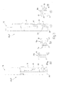
- Number 1 in Figure 1 indicates as a whole a machine for machining door and window frame component parts 2 of wood or similar, and which comprises an elongated, substantially U-shaped bed 3 extending in a horizontal direction 4 and having two lateral longitudinal members 5 extending parallel to direction 4 and each supporting a respective rail 6 also parallel to direction 4.
- Machine 1 also comprises a bridge 7, in turn comprising an upright 8 which is fitted in known manner to bed 3, is moved linearly in direction 4 along bed 3 by a known actuating device not shown, and is fitted on its free end with a cross member 9 extending over bed 3 in a horizontal direction 10 crosswise to direction 4, and bounded laterally by two opposite faces 11, 12 substantially perpendicular to direction 4.
- Bridge 7 supports a known machining head 13 which is fitted to face 11, is fitted in known manner to cross member 9 to move linearly along cross member 9 in direction 10, and comprises at least one tool spindle (not shown) fitted in known manner to head 13 to move in a vertical direction 14 perpendicular to directions 4 and 10.
- Machine 1 also comprises a number of cross members 15 - hereinafter referred to as "work surfaces” - which extend between rails 6 in direction 10, and are fitted to rails 6 to slide manually, or by means of respective known actuating devices not shown, along rails 6 in direction 4.
- Work surfaces 15 support a number of clamps 16, the arrangement of which on relative work surfaces 15 substantially depends on the size of, and the type of work to be carried out on, component parts 2.
- each clamp 16 comprises a fixed bottom jaw 17 fixed to relative work surface 15 and defining, with jaws 17 of the other clamps 16, a substantially horizontal supporting surface P1 for at least one component part 2; and a movable top jaw 18 which extends parallel to surface P1, is fitted to the free end of an output rod (not shown) of an actuating cylinder (not shown), and is moved by the actuating cylinder (not shown) between a clamped position ( Figure 1 ) and a release position respectively clamping and releasing component part 2.
- Machine 1 also comprises a feed device 19 for component parts 2, which comprises a bed 20 located alongside bed 3 in direction 4 and supporting a number of belt conveyors 21, which are aligned in direction 4, extend in respective vertical planes parallel to one another and to direction 10, and have respective coplanar top conveying branches defining a horizontal conveying surface P2 parallel to surface P1.
- a feed device 19 for component parts 2 which comprises a bed 20 located alongside bed 3 in direction 4 and supporting a number of belt conveyors 21, which are aligned in direction 4, extend in respective vertical planes parallel to one another and to direction 10, and have respective coplanar top conveying branches defining a horizontal conveying surface P2 parallel to surface P1.
- Conveyors 21 extend in direction 10 between a loading station 22 where component parts 2 for machining are loaded onto device 19, and an unloading station 23 where component parts 2 for machining are unloaded off device 19.
- Component parts 2 are transferred between clamps 16 and feed device 19 by a grip-and-carry assembly 24 comprising an arm 25, which projects in direction 4 from face 12 of cross member 9, is fitted in known manner to cross member 9 to move linearly along cross member 9 in direction 10 under the control of a known actuating device not shown, and is fitted, in the example shown, with two grip-and-carry device 26, 27 movable with respect to each other in direction 4.
- a grip-and-carry assembly 24 comprising an arm 25, which projects in direction 4 from face 12 of cross member 9, is fitted in known manner to cross member 9 to move linearly along cross member 9 in direction 10 under the control of a known actuating device not shown, and is fitted, in the example shown, with two grip-and-carry device 26, 27 movable with respect to each other in direction 4.
- device 26 is fixed to arm 25 in direction 4, while device 27 is fitted in known manner to arm 25 to move linearly along arm 25 in direction 4 under the control of a known actuating device not shown.
- each device 26, 27 comprises a gripper, in turn comprising a substantially L-shaped bottom jaw 28 movable in direction 14 under the control of a known actuating device not shown; and a top jaw 29 which is fitted to the free end of an output rod 30 of an actuating cylinder 31 fixed to jaw 28, and is moved by actuating cylinder 31 between a grip position and a release position respectively gripping and releasing component part 2.
- component parts 2 are loaded successively onto device 19 at loading station 22, either manually or by means of a known loader not shown, are positioned contacting at least two known stops (not shown) located at station 22 to ensure each component part 2 is positioned correctly in direction 10, and are then fed successively in steps to unloading station 23.
- component parts 2 are loaded onto feed device 19, the component part 2 located at station 23 is transferred by grip-and-carry assembly 24 to clamps 16 for machining by machining head 13, feed device 19 is operated to move another component part 2 into station 23, and the machined component part 2 is transferred by assembly 24 from clamps 16 to station 22.
- the component part 2 unloaded at station 22 is then moved forward, behind the component parts 2 already unloaded at station 22 ( Figure 2 ), by a push device (not shown) operated independently of feed device 19 when device 19 is stopped.
- the component part 2 for machining is picked up from station 23 by assembly 24; is inserted by assembly 24 inside at least one first clamp 16 (hereinafter indicated 16a) in an insertion direction 10a parallel to direction 10 ( Figure 3a ) to enable machining head 13 to machine a first side 2a of component part 2 ( Figure 3b ); is withdrawn from clamp 16a by assembly 24 ( Figure 3c ); and is inserted by assembly 24 inside at least one second clamp 16 (hereinafter indicated 16b) in an insertion direction 10b parallel to and opposite direction 10a, to enable machining head 13 to machine a second side 2b, opposite side 2a, of component part 2 ( Figure 3d ).
- component part 2 may be withdrawn from clamp 16a, moved in directions 10 and 14 onto the opposite side of clamp 16a, and inserted once more into the same clamp 16a in direction 10b to also machine side 2b.
- grip-and-carry devices 26, 27 are replaced by respective dual grip-and-carry devices 32, 33, each comprising a respective slide 34, which is movable in direction 14 and supports two superimposed grippers 35, 36, with gripper 35 located over gripper 36.
- Gripper 35 comprises a bottom jaw 37 projecting in direction 10 from slide 34 and cooperating with a top jaw 38, which is movable in direction 14, with respect to slide 34 and under the control of an actuating cylinder 39 fixed to slide 34, between a grip position and a release position respectively gripping and releasing a first component part 2; and gripper 36 comprises a top jaw defined by bottom jaw 37 of gripper 35, and a bottom jaw 40, which is movable in direction 14, with respect to slide 34 and under the control of an actuating cylinder 41 fixed to slide 34, between a grip position and a release position respectively gripping and releasing a second component part 2.
- slide 34 of device 33 is in turn fitted to a slide (not shown) movable in direction 4 along arm 25.
- grip-and-carry assembly 24 in Figure 4 In actual use, at each operating cycle, grip-and-carry assembly 24 in Figure 4 :
- feed device 19 is replaced by two feed devices 42, which are identical to device 19, define two parallel, superimposed supporting surfaces P2, and are located one (hereinafter indicated 42a) over the other (hereinafter indicated 42b).
- Device 42a extends between loading station 22 and unloading station 23, and successively feeds component parts 2 for machining from station 22 to station 23; and device 42b feeds the machined component part 2 from an input station 43, projecting beyond station 23 in direction 10, to an output station 44 opposite station 43 and located at station 22.
- device 42b is associated with a lifting device 45 comprising a substantially vertical supporting beam 46 facing bed 20 of devices 42a, 42b in direction 10; and a number of arms 47, which project from beam 46 in direction 10, are offset with respect to belt conveyors 21 of device 42b in direction 4, and define a supporting surface P3 for at least one machined component part 2.
- Beam 46 is movable in direction 14 between a raised position, in which device 45 receives the machined component part 2 from assembly 24, and a lowered position, in which arms 47 are positioned between conveyors 21, and surface P3 is positioned below surface P2 of device 42b.
- component parts 2 for machining are fed successively by device 42a from loading station 22 to unloading station 23, are picked up successively at station 23 by assembly 24, are transferred to clamps 16, and are machined by head 13.
- the machined component parts 2 are removed from clamps 16 by assembly 24, are released by assembly 24 onto surface P3 when device 45 is in the raised position, are lowered by device 45 at input station 43, are released by device 45 onto device 42b, and are fed by device 42b to output station 44.
- lifting device 45 may be eliminated, and the machined component parts 2 released directly by assembly 24 at input station 43 of device 42b.
- component parts 2 for machining may be loaded onto device 42a at station 22, and the machined component parts 2 unloaded off device 42b at station 44 either manually or automatically by means of respective feed devices, possibly associated with further machines identical to machine 1.
- bridge 7 supports machining head 13 only, and grip-and-carry assembly 24 is fitted to a further bridge identical to bridge 7.
Landscapes
- Engineering & Computer Science (AREA)
- Life Sciences & Earth Sciences (AREA)
- Mechanical Engineering (AREA)
- Wood Science & Technology (AREA)
- Forests & Forestry (AREA)
- Milling, Drilling, And Turning Of Wood (AREA)
- Feeding Of Workpieces (AREA)
- Door And Window Frames Mounted To Openings (AREA)
- Automatic Assembly (AREA)
- Multi-Process Working Machines And Systems (AREA)
- Chemical And Physical Treatments For Wood And The Like (AREA)
Applications Claiming Priority (2)
| Application Number | Priority Date | Filing Date | Title |
|---|---|---|---|
| IT000356A ITBO20070356A1 (it) | 2007-05-14 | 2007-05-14 | Metodo per la lavorazione di componenti di legno o simili, in particolare componenti per infissi |
| EP07121372A EP1992464B1 (de) | 2007-05-14 | 2007-11-22 | Bearbeitungsverfahren von einem Bauteil aus Holz oder dergleichen, insbesondere für Bestandteile von Tür- oder Fensterrahmen |
Related Parent Applications (1)
| Application Number | Title | Priority Date | Filing Date |
|---|---|---|---|
| EP07121372.2 Division | 2007-11-22 |
Publications (2)
| Publication Number | Publication Date |
|---|---|
| EP2241425A1 true EP2241425A1 (de) | 2010-10-20 |
| EP2241425B1 EP2241425B1 (de) | 2012-03-14 |
Family
ID=39639557
Family Applications (2)
| Application Number | Title | Priority Date | Filing Date |
|---|---|---|---|
| EP07121372A Active EP1992464B1 (de) | 2007-05-14 | 2007-11-22 | Bearbeitungsverfahren von einem Bauteil aus Holz oder dergleichen, insbesondere für Bestandteile von Tür- oder Fensterrahmen |
| EP10172236A Active EP2241425B1 (de) | 2007-05-14 | 2007-11-22 | Bearbeitungsverfahren von einem Bauteil aus Holz oder dergleichen, insbesondere für Bestandteile von Tür- oder Fensterrahmen |
Family Applications Before (1)
| Application Number | Title | Priority Date | Filing Date |
|---|---|---|---|
| EP07121372A Active EP1992464B1 (de) | 2007-05-14 | 2007-11-22 | Bearbeitungsverfahren von einem Bauteil aus Holz oder dergleichen, insbesondere für Bestandteile von Tür- oder Fensterrahmen |
Country Status (3)
| Country | Link |
|---|---|
| EP (2) | EP1992464B1 (de) |
| AT (2) | ATE549142T1 (de) |
| IT (1) | ITBO20070356A1 (de) |
Cited By (4)
| Publication number | Priority date | Publication date | Assignee | Title |
|---|---|---|---|---|
| DE102015212541A1 (de) * | 2014-09-22 | 2016-03-24 | Homag Holzbearbeitungssysteme Gmbh | Bearbeitungsvorrichtung |
| JP2018195019A (ja) * | 2017-05-16 | 2018-12-06 | 株式会社平安コーポレーション | プレカット加工方法及びそのシステム |
| JP2020113293A (ja) * | 2020-02-27 | 2020-07-27 | 株式会社平安コーポレーション | プレカット加工方法及びそのシステム |
| CN112705986A (zh) * | 2020-12-21 | 2021-04-27 | 常州工程职业技术学院 | 一种机械加工用自动化上料装置 |
Families Citing this family (16)
| Publication number | Priority date | Publication date | Assignee | Title |
|---|---|---|---|---|
| ITBO20080140A1 (it) * | 2008-03-03 | 2009-09-04 | Biesse Spa | Metodo e macchina per la lavorazione di componenti di legno o simili |
| DE102008032302A1 (de) * | 2008-07-09 | 2010-01-14 | Weinmann Holzbausystemtechnik Gmbh | Vorrichtung zum Fördern eines Werkstücks |
| IT1391400B1 (it) * | 2008-09-02 | 2011-12-23 | Biesse Spa | Centro di lavoro per la lavorazione di componenti di legno o simili di forma allungata, in particolare componenti per infissi |
| WO2010041285A1 (en) * | 2008-10-10 | 2010-04-15 | Working Process S.R.L. | Working center |
| IT1408447B1 (it) * | 2010-10-21 | 2014-06-20 | Working Process S R L | Centro di lavoro con manipolatore perfezionato |
| IT1402782B1 (it) * | 2010-10-21 | 2013-09-18 | Working Process S R L | Centro di lavoro con piano di riscontro e raddrizzamento separato |
| IT1402597B1 (it) * | 2010-10-21 | 2013-09-13 | Working Process S R L | Centro di lavoro |
| DE102014223910A1 (de) * | 2014-11-24 | 2016-05-25 | Homag Holzbearbeitungssysteme Gmbh | Werkstückzuführvorrichtung |
| DE102015204719A1 (de) * | 2015-03-16 | 2016-09-22 | Homag Holzbearbeitungssysteme Gmbh | Bearbeitungsvorrichtung |
| ITRN20150015A1 (it) * | 2015-04-22 | 2016-10-22 | Masterwood Spa | Centro di lavorazione automatico per componenti di infissi. |
| DE102015208618A1 (de) * | 2015-05-08 | 2016-11-10 | Homag Gmbh | Werkstückzuführvorrichtung bzw. Werkstückabführvorrichtung |
| DE102015218814A1 (de) | 2015-09-29 | 2017-03-30 | Homag Gmbh | Bearbeitungsvorrichtung |
| CN106625983A (zh) * | 2015-11-02 | 2017-05-10 | 东北林业大学 | 数控下回料两台封边机生产线 |
| CN106925804A (zh) * | 2017-04-07 | 2017-07-07 | 南兴装备股份有限公司 | 自动进出料自动扫条码的智能化通过式数控钻设备 |
| EP3950218B1 (de) * | 2020-08-03 | 2024-10-02 | F.O.M. Industrie S.r.l. | Arbeitsstation zur verarbeitung von profilstäben, insbesondere aus aluminium, leichtlegierungen, pvc oder dergleichen |
| EP3950217B1 (de) * | 2020-08-03 | 2024-07-10 | F.O.M. Industrie S.r.l. | Verfahren zum einrichten eines arbeitsplatzes zum bearbeiten von profilstäben, insbesondere aus aluminium, leichtlegierungen, pvc oder dergleichen |
Citations (4)
| Publication number | Priority date | Publication date | Assignee | Title |
|---|---|---|---|---|
| EP0724939A1 (de) * | 1995-02-04 | 1996-08-07 | Hans Hundegger | Abbundanlage zum Bearbeiten von Werkstücken, insbesondere Brettern, Kanthölzern und dergleichen |
| EP0894565A2 (de) * | 1997-08-02 | 1999-02-03 | Engelbert Güntert | Abbundanlage |
| DE10030997A1 (de) * | 1999-07-02 | 2001-01-11 | Biesse Spa | Anlage zum Bearbeiten von ebenen Körpern, insbesondere von Holztafeln |
| DE202004005893U1 (de) * | 2003-05-26 | 2004-06-09 | Celaschi S.P.A., Vigolzone | Holzbearbeitungsmaschine für Rahmenteile |
Family Cites Families (4)
| Publication number | Priority date | Publication date | Assignee | Title |
|---|---|---|---|---|
| DE19752685A1 (de) * | 1997-11-28 | 1999-07-01 | Ima Maschinenfabriken Klessmann Gmbh | Maschine zum Bearbeiten von Fensterrahmen-Holmen |
| IT1320885B1 (it) * | 2000-02-22 | 2003-12-10 | Biesse Spa | Macchina per la lavorazione di pannelli di legno o similari |
| ITBO20010643A1 (it) * | 2001-10-19 | 2003-04-19 | Impresa 2000 Di Sacchi Paride | Metodo e macchina per la lavorazione di componenti di legno o simili |
| ITMO20060021A1 (it) * | 2006-01-20 | 2007-07-21 | Scm Group Spa | Macchina utensile |
-
2007
- 2007-05-14 IT IT000356A patent/ITBO20070356A1/it unknown
- 2007-11-22 EP EP07121372A patent/EP1992464B1/de active Active
- 2007-11-22 AT AT10172236T patent/ATE549142T1/de active
- 2007-11-22 EP EP10172236A patent/EP2241425B1/de active Active
- 2007-11-22 AT AT07121372T patent/ATE552953T1/de active
Patent Citations (4)
| Publication number | Priority date | Publication date | Assignee | Title |
|---|---|---|---|---|
| EP0724939A1 (de) * | 1995-02-04 | 1996-08-07 | Hans Hundegger | Abbundanlage zum Bearbeiten von Werkstücken, insbesondere Brettern, Kanthölzern und dergleichen |
| EP0894565A2 (de) * | 1997-08-02 | 1999-02-03 | Engelbert Güntert | Abbundanlage |
| DE10030997A1 (de) * | 1999-07-02 | 2001-01-11 | Biesse Spa | Anlage zum Bearbeiten von ebenen Körpern, insbesondere von Holztafeln |
| DE202004005893U1 (de) * | 2003-05-26 | 2004-06-09 | Celaschi S.P.A., Vigolzone | Holzbearbeitungsmaschine für Rahmenteile |
Cited By (5)
| Publication number | Priority date | Publication date | Assignee | Title |
|---|---|---|---|---|
| DE102015212541A1 (de) * | 2014-09-22 | 2016-03-24 | Homag Holzbearbeitungssysteme Gmbh | Bearbeitungsvorrichtung |
| US10668643B2 (en) | 2014-09-22 | 2020-06-02 | Homag Gmbh | Machining device |
| JP2018195019A (ja) * | 2017-05-16 | 2018-12-06 | 株式会社平安コーポレーション | プレカット加工方法及びそのシステム |
| JP2020113293A (ja) * | 2020-02-27 | 2020-07-27 | 株式会社平安コーポレーション | プレカット加工方法及びそのシステム |
| CN112705986A (zh) * | 2020-12-21 | 2021-04-27 | 常州工程职业技术学院 | 一种机械加工用自动化上料装置 |
Also Published As
| Publication number | Publication date |
|---|---|
| EP2241425B1 (de) | 2012-03-14 |
| EP1992464A3 (de) | 2009-09-02 |
| EP1992464B1 (de) | 2012-04-11 |
| EP1992464A2 (de) | 2008-11-19 |
| ATE552953T1 (de) | 2012-04-15 |
| ATE549142T1 (de) | 2012-03-15 |
| ITBO20070356A1 (it) | 2008-11-15 |
Similar Documents
| Publication | Publication Date | Title |
|---|---|---|
| EP2241425B1 (de) | Bearbeitungsverfahren von einem Bauteil aus Holz oder dergleichen, insbesondere für Bestandteile von Tür- oder Fensterrahmen | |
| EP1810803B1 (de) | Maschine zur Bearbeitung von Holzelementen mit automatischer Ladung und Entladung dieser Elemente sowie Verfahren zum Laden dieser Elemente | |
| CN106794594B (zh) | 加工装置 | |
| AU2020217311B2 (en) | Processing machine for flat material parts with a support unit and method therefor | |
| CN101312805B (zh) | 机床 | |
| EP1810802A1 (de) | Werkzeugmaschine | |
| CN109562431B (zh) | 用于机器的装载和卸载装置、用于加工板状工件的机器、用于这种机器的工件支撑件及装载和卸载这种机器的方法 | |
| EP2305440A1 (de) | Verfahren und Vorrichtung zur Verarbeitung von Bauteilen aus Holz und dergleichen | |
| CN114786869B (zh) | 具有至少两个加工机器人的加工单元 | |
| KR100889009B1 (ko) | 누적공차 최소화 및 다기종 센터링기능이 구비되는 이송및 삽입 적재장치 및 방법 | |
| CN114453496B (zh) | 一种电动剃须刀刀片的冲压成型设备 | |
| EP2842705A1 (de) | Verfahren und Maschine zur Verarbeitung von Holzkomponenten oder Ähnlichem | |
| CN110181075B (zh) | 加工装置 | |
| EP2098344B2 (de) | Verfahren und Vorrichtung zur maschinellen Verarbeitung von Holzkomponenten oder Ähnlichem | |
| US11040426B2 (en) | Machine tool having a tool spindle and a loading portal | |
| EP1250213B1 (de) | Werkzeugmaschine und verfahren zur bearbeitung von länglichen elementen, insbesondere metallischen profilelementen | |
| EP2105269A2 (de) | Verfahren und Maschine zur Profilierung verlängerter Holzkomponenten oder ähnlicher Elemente, insbesondere für Tür- und Fensterrahmen | |
| US12145191B2 (en) | Bending system and tool transport method | |
| EP2210723A1 (de) | Machine und Verfahren für die Bearbeitung von Holz oder ähnlichen Materialien | |
| CN210125734U (zh) | 加工装置 | |
| JP7083188B2 (ja) | マニピュレータのクランプ構造及びそれを用いた板材の曲げ加工方法 | |
| CN210968022U (zh) | 一种汽车零部件工件装夹系统 | |
| CN114039259B (zh) | 一种实现定位组装及存线的线束加工设备 | |
| CN210388249U (zh) | 一种装配设备及流水线系统 | |
| CN214421615U (zh) | 一种接头上料机构 |
Legal Events
| Date | Code | Title | Description |
|---|---|---|---|
| PUAI | Public reference made under article 153(3) epc to a published international application that has entered the european phase |
Free format text: ORIGINAL CODE: 0009012 |
|
| AC | Divisional application: reference to earlier application |
Ref document number: 1992464 Country of ref document: EP Kind code of ref document: P |
|
| AK | Designated contracting states |
Kind code of ref document: A1 Designated state(s): AT BE BG CH CY CZ DE DK EE ES FI FR GB GR HU IE IS IT LI LT LU LV MC MT NL PL PT RO SE SI SK TR |
|
| 17P | Request for examination filed |
Effective date: 20110420 |
|
| RIC1 | Information provided on ipc code assigned before grant |
Ipc: B23Q 7/04 20060101ALI20110706BHEP Ipc: B27F 1/04 20060101ALI20110706BHEP Ipc: B27M 1/08 20060101AFI20110706BHEP |
|
| GRAP | Despatch of communication of intention to grant a patent |
Free format text: ORIGINAL CODE: EPIDOSNIGR1 |
|
| GRAS | Grant fee paid |
Free format text: ORIGINAL CODE: EPIDOSNIGR3 |
|
| GRAA | (expected) grant |
Free format text: ORIGINAL CODE: 0009210 |
|
| AC | Divisional application: reference to earlier application |
Ref document number: 1992464 Country of ref document: EP Kind code of ref document: P |
|
| AK | Designated contracting states |
Kind code of ref document: B1 Designated state(s): AT BE BG CH CY CZ DE DK EE ES FI FR GB GR HU IE IS IT LI LT LU LV MC MT NL PL PT RO SE SI SK TR |
|
| REG | Reference to a national code |
Ref country code: GB Ref legal event code: FG4D |
|
| REG | Reference to a national code |
Ref country code: AT Ref legal event code: REF Ref document number: 549142 Country of ref document: AT Kind code of ref document: T Effective date: 20120315 Ref country code: CH Ref legal event code: EP |
|
| REG | Reference to a national code |
Ref country code: IE Ref legal event code: FG4D |
|
| REG | Reference to a national code |
Ref country code: DE Ref legal event code: R096 Ref document number: 602007021389 Country of ref document: DE Effective date: 20120510 |
|
| REG | Reference to a national code |
Ref country code: NL Ref legal event code: VDEP Effective date: 20120314 |
|
| PG25 | Lapsed in a contracting state [announced via postgrant information from national office to epo] |
Ref country code: LT Free format text: LAPSE BECAUSE OF FAILURE TO SUBMIT A TRANSLATION OF THE DESCRIPTION OR TO PAY THE FEE WITHIN THE PRESCRIBED TIME-LIMIT Effective date: 20120314 |
|
| LTIE | Lt: invalidation of european patent or patent extension |
Effective date: 20120314 |
|
| PG25 | Lapsed in a contracting state [announced via postgrant information from national office to epo] |
Ref country code: FI Free format text: LAPSE BECAUSE OF FAILURE TO SUBMIT A TRANSLATION OF THE DESCRIPTION OR TO PAY THE FEE WITHIN THE PRESCRIBED TIME-LIMIT Effective date: 20120314 Ref country code: GR Free format text: LAPSE BECAUSE OF FAILURE TO SUBMIT A TRANSLATION OF THE DESCRIPTION OR TO PAY THE FEE WITHIN THE PRESCRIBED TIME-LIMIT Effective date: 20120615 Ref country code: LV Free format text: LAPSE BECAUSE OF FAILURE TO SUBMIT A TRANSLATION OF THE DESCRIPTION OR TO PAY THE FEE WITHIN THE PRESCRIBED TIME-LIMIT Effective date: 20120314 |
|
| PG25 | Lapsed in a contracting state [announced via postgrant information from national office to epo] |
Ref country code: CY Free format text: LAPSE BECAUSE OF FAILURE TO SUBMIT A TRANSLATION OF THE DESCRIPTION OR TO PAY THE FEE WITHIN THE PRESCRIBED TIME-LIMIT Effective date: 20120314 |
|
| PG25 | Lapsed in a contracting state [announced via postgrant information from national office to epo] |
Ref country code: BE Free format text: LAPSE BECAUSE OF FAILURE TO SUBMIT A TRANSLATION OF THE DESCRIPTION OR TO PAY THE FEE WITHIN THE PRESCRIBED TIME-LIMIT Effective date: 20120314 Ref country code: RO Free format text: LAPSE BECAUSE OF FAILURE TO SUBMIT A TRANSLATION OF THE DESCRIPTION OR TO PAY THE FEE WITHIN THE PRESCRIBED TIME-LIMIT Effective date: 20120314 Ref country code: IS Free format text: LAPSE BECAUSE OF FAILURE TO SUBMIT A TRANSLATION OF THE DESCRIPTION OR TO PAY THE FEE WITHIN THE PRESCRIBED TIME-LIMIT Effective date: 20120714 Ref country code: EE Free format text: LAPSE BECAUSE OF FAILURE TO SUBMIT A TRANSLATION OF THE DESCRIPTION OR TO PAY THE FEE WITHIN THE PRESCRIBED TIME-LIMIT Effective date: 20120314 Ref country code: SI Free format text: LAPSE BECAUSE OF FAILURE TO SUBMIT A TRANSLATION OF THE DESCRIPTION OR TO PAY THE FEE WITHIN THE PRESCRIBED TIME-LIMIT Effective date: 20120314 Ref country code: SE Free format text: LAPSE BECAUSE OF FAILURE TO SUBMIT A TRANSLATION OF THE DESCRIPTION OR TO PAY THE FEE WITHIN THE PRESCRIBED TIME-LIMIT Effective date: 20120314 Ref country code: CZ Free format text: LAPSE BECAUSE OF FAILURE TO SUBMIT A TRANSLATION OF THE DESCRIPTION OR TO PAY THE FEE WITHIN THE PRESCRIBED TIME-LIMIT Effective date: 20120314 Ref country code: PL Free format text: LAPSE BECAUSE OF FAILURE TO SUBMIT A TRANSLATION OF THE DESCRIPTION OR TO PAY THE FEE WITHIN THE PRESCRIBED TIME-LIMIT Effective date: 20120314 |
|
| PG25 | Lapsed in a contracting state [announced via postgrant information from national office to epo] |
Ref country code: SK Free format text: LAPSE BECAUSE OF FAILURE TO SUBMIT A TRANSLATION OF THE DESCRIPTION OR TO PAY THE FEE WITHIN THE PRESCRIBED TIME-LIMIT Effective date: 20120314 Ref country code: PT Free format text: LAPSE BECAUSE OF FAILURE TO SUBMIT A TRANSLATION OF THE DESCRIPTION OR TO PAY THE FEE WITHIN THE PRESCRIBED TIME-LIMIT Effective date: 20120716 |
|
| PLBE | No opposition filed within time limit |
Free format text: ORIGINAL CODE: 0009261 |
|
| STAA | Information on the status of an ep patent application or granted ep patent |
Free format text: STATUS: NO OPPOSITION FILED WITHIN TIME LIMIT |
|
| PG25 | Lapsed in a contracting state [announced via postgrant information from national office to epo] |
Ref country code: NL Free format text: LAPSE BECAUSE OF FAILURE TO SUBMIT A TRANSLATION OF THE DESCRIPTION OR TO PAY THE FEE WITHIN THE PRESCRIBED TIME-LIMIT Effective date: 20120314 Ref country code: DK Free format text: LAPSE BECAUSE OF FAILURE TO SUBMIT A TRANSLATION OF THE DESCRIPTION OR TO PAY THE FEE WITHIN THE PRESCRIBED TIME-LIMIT Effective date: 20120314 |
|
| 26N | No opposition filed |
Effective date: 20121217 |
|
| PG25 | Lapsed in a contracting state [announced via postgrant information from national office to epo] |
Ref country code: IT Free format text: LAPSE BECAUSE OF FAILURE TO SUBMIT A TRANSLATION OF THE DESCRIPTION OR TO PAY THE FEE WITHIN THE PRESCRIBED TIME-LIMIT Effective date: 20120314 |
|
| REG | Reference to a national code |
Ref country code: DE Ref legal event code: R097 Ref document number: 602007021389 Country of ref document: DE Effective date: 20121217 |
|
| PG25 | Lapsed in a contracting state [announced via postgrant information from national office to epo] |
Ref country code: ES Free format text: LAPSE BECAUSE OF FAILURE TO SUBMIT A TRANSLATION OF THE DESCRIPTION OR TO PAY THE FEE WITHIN THE PRESCRIBED TIME-LIMIT Effective date: 20120625 |
|
| REG | Reference to a national code |
Ref country code: CH Ref legal event code: PL |
|
| GBPC | Gb: european patent ceased through non-payment of renewal fee |
Effective date: 20121122 |
|
| PG25 | Lapsed in a contracting state [announced via postgrant information from national office to epo] |
Ref country code: BG Free format text: LAPSE BECAUSE OF FAILURE TO SUBMIT A TRANSLATION OF THE DESCRIPTION OR TO PAY THE FEE WITHIN THE PRESCRIBED TIME-LIMIT Effective date: 20120614 Ref country code: CH Free format text: LAPSE BECAUSE OF NON-PAYMENT OF DUE FEES Effective date: 20121130 Ref country code: LI Free format text: LAPSE BECAUSE OF NON-PAYMENT OF DUE FEES Effective date: 20121130 |
|
| REG | Reference to a national code |
Ref country code: IE Ref legal event code: MM4A |
|
| REG | Reference to a national code |
Ref country code: FR Ref legal event code: ST Effective date: 20130731 |
|
| PG25 | Lapsed in a contracting state [announced via postgrant information from national office to epo] |
Ref country code: IE Free format text: LAPSE BECAUSE OF NON-PAYMENT OF DUE FEES Effective date: 20121122 |
|
| PG25 | Lapsed in a contracting state [announced via postgrant information from national office to epo] |
Ref country code: MT Free format text: LAPSE BECAUSE OF FAILURE TO SUBMIT A TRANSLATION OF THE DESCRIPTION OR TO PAY THE FEE WITHIN THE PRESCRIBED TIME-LIMIT Effective date: 20120314 Ref country code: FR Free format text: LAPSE BECAUSE OF NON-PAYMENT OF DUE FEES Effective date: 20121130 Ref country code: GB Free format text: LAPSE BECAUSE OF NON-PAYMENT OF DUE FEES Effective date: 20121122 |
|
| PG25 | Lapsed in a contracting state [announced via postgrant information from national office to epo] |
Ref country code: MC Free format text: LAPSE BECAUSE OF NON-PAYMENT OF DUE FEES Effective date: 20121130 Ref country code: TR Free format text: LAPSE BECAUSE OF FAILURE TO SUBMIT A TRANSLATION OF THE DESCRIPTION OR TO PAY THE FEE WITHIN THE PRESCRIBED TIME-LIMIT Effective date: 20120314 |
|
| PG25 | Lapsed in a contracting state [announced via postgrant information from national office to epo] |
Ref country code: LU Free format text: LAPSE BECAUSE OF NON-PAYMENT OF DUE FEES Effective date: 20121122 |
|
| PG25 | Lapsed in a contracting state [announced via postgrant information from national office to epo] |
Ref country code: HU Free format text: LAPSE BECAUSE OF FAILURE TO SUBMIT A TRANSLATION OF THE DESCRIPTION OR TO PAY THE FEE WITHIN THE PRESCRIBED TIME-LIMIT Effective date: 20071122 |
|
| PGFP | Annual fee paid to national office [announced via postgrant information from national office to epo] |
Ref country code: DE Payment date: 20251126 Year of fee payment: 19 |
|
| PGFP | Annual fee paid to national office [announced via postgrant information from national office to epo] |
Ref country code: AT Payment date: 20251118 Year of fee payment: 19 |