EP2241704A1 - Device for mechanical interconnection to a square axis for door handles - Google Patents
Device for mechanical interconnection to a square axis for door handles Download PDFInfo
- Publication number
- EP2241704A1 EP2241704A1 EP20100160068 EP10160068A EP2241704A1 EP 2241704 A1 EP2241704 A1 EP 2241704A1 EP 20100160068 EP20100160068 EP 20100160068 EP 10160068 A EP10160068 A EP 10160068A EP 2241704 A1 EP2241704 A1 EP 2241704A1
- Authority
- EP
- European Patent Office
- Prior art keywords
- rod
- operating position
- retaining element
- opening
- enable
- Prior art date
- Legal status (The legal status is an assumption and is not a legal conclusion. Google has not performed a legal analysis and makes no representation as to the accuracy of the status listed.)
- Withdrawn
Links
- 230000008878 coupling Effects 0.000 claims abstract description 23
- 238000010168 coupling process Methods 0.000 claims abstract description 23
- 238000005859 coupling reaction Methods 0.000 claims abstract description 23
- 238000003780 insertion Methods 0.000 claims abstract description 16
- 230000037431 insertion Effects 0.000 claims abstract description 16
- 238000000605 extraction Methods 0.000 claims abstract description 13
- 230000003213 activating effect Effects 0.000 claims description 16
- 238000000034 method Methods 0.000 claims description 3
- 238000006073 displacement reaction Methods 0.000 description 3
- 230000000694 effects Effects 0.000 description 2
- 230000001419 dependent effect Effects 0.000 description 1
- 238000004519 manufacturing process Methods 0.000 description 1
Images



Classifications
-
- E—FIXED CONSTRUCTIONS
- E05—LOCKS; KEYS; WINDOW OR DOOR FITTINGS; SAFES
- E05B—LOCKS; ACCESSORIES THEREFOR; HANDCUFFS
- E05B3/00—Fastening knobs or handles to lock or latch parts
- E05B3/04—Fastening the knob or the handle shank to the spindle by screws, springs or snap bolts
-
- E—FIXED CONSTRUCTIONS
- E05—LOCKS; KEYS; WINDOW OR DOOR FITTINGS; SAFES
- E05B—LOCKS; ACCESSORIES THEREFOR; HANDCUFFS
- E05B3/00—Fastening knobs or handles to lock or latch parts
- E05B2003/006—Fastening knobs or handles to the spindle by means of tilt-plates
Definitions
- the invention relates to a mechanical connection with a rod.
- the invention relates to a mechanical interconnection device with a rod for mounting door handles.
- door handles are generally mounted on respective rods by inserting the rods in interconnecting openings afforded on the body of the handles and then fastening the handles on the rods using fastening screws which are inserted and screwed into respective holes realised on the body of the handles. The screw is then screwed up to constraining the rod internally of the door handle, possibly in a housing seating afforded in the rod, thus fastening handle and rod together.
- the handle rod is then coupled to a respective rotation mechanism housed internally of the door and another handle is mounted to the other end of the rod.
- the technical objective underlying the present invention is to make available a device for mechanical interconnection with a rod which obviates the above-cited drawbacks.
- a particular aim of the present invention is to realise a mechanical interconnection device with a rod for mounting door handles.
- one of the aims of the present invention is to provide a device for door handles which is able to accelerate and considerably simplify the mounting and/or demounting operations of door handles.
- a further aim of the present invention is to provide a device which can be used with any handle.
- a still further aim of the present invention is to make available a device which is simple and economical to manufacture.
- the invention relates to a device as in any one of the claims in which the through-opening exhibits a main central axis that coincides with a main central axis of a coupling opening in a first operating position, inclined with respect to the main central axis of the coupling opening in a second operating position.
- the invention relates to a device of any one of the claims wherein the passage opening and/or the coupling opening are substantially complementarily-shaped to the section of the rod.
- the invention relates to a device of any one of the claims, characterised in that it further comprises a rod which is insertable in the body.
- the invention relates to a device as in any one of the claims wherein in the first operating position the through-opening exhibits a projection on the plane that is perpendicular to the insertion direction which projection is larger than the section of the rod and in the second position the projection of the coupling opening on the plane exhibits at least a smaller dimension that the corresponding of the rod section.
- the invention relates to a method as in claim 10 which further comprises a stage of removing the rod by acting on the activating portion of the retaining element in order to displace the retaining element towards the first opening position, thus freeing the rod, enabling its extraction from the coupling opening.
- a mechanical interconnecting device with a stem for mounting door handles of the present invention is denoted in its entirety by reference number 1.
- the device 1 comprises a body 2 provided with a coupling opening 3 destined to enable insertion of a rod 4 internally thereof, in an insertion sense 26a along an insertion direction 26, for coupling the body 2 to the rod 4.
- the device 1 further comprises a retaining element 5 provided with a through-opening 6 having a profile 7 destined to be crossed by the rod 4.
- the retaining element 5 is housed in a seating 8 afforded in a portion of the coupling opening 3 of the body 2 configured such as to enable displacement of the retaining element 5 internally of the body 2.
- the displacement is made between a first operating position in which the retaining element 5 exhibits the through-opening 6 arranged such as to enable passage of the stem 4 and a second operating position in which at least a portion of the profile 7 of the through-opening 6 interferes with the rod 4 in order to prevent extraction thereof from the body 2.
- At least two portions of profile 7 enter into contact with the surface of the stem 4 in the second operating position.
- the through-opening 6 preferably exhibits a projection on the plane that is perpendicular to the insertion direction having at least a predetermined dimension which is destined to enable passage of the rod 4, while in the second position the dimension of the projection of the coupling opening on the plane is smaller than the predetermined dimension.
- the retaining element 5 is advantageously arranged perpendicular to the insertion direction of the rod 4 when in the first operating position and is instead inclined when in the second operating position.
- the retaining element 5 is displaceable from the second operating position to the first operating position by effect of the thrust exerted by the rod 4 during the insertion of the body 2 and is displaceable towards the second operation position by effect of the thrust exerted by the rod 4 in extraction from the coupling opening 3.
- the body 2 further comprises a closing element 9 destined to contain the retaining element 5 internally of the body 2 and provided with a central opening 10 which enables the rod 4 to cross.
- the closing element 9 exhibits a first external surface 12 and a second rest surface 13 facing towards the inside of the seating 8 and complementarily-inclined with respect to the inclination assumed by the retaining element 5 when in the second operating position.
- a first rest surface 11 on the seating 8 is defined at the coupling opening 3, defining the first operating position of the retaining element 5, while the second rest surface 13 of the closing element 9 defines, for the retaining element 5, the second operating position and is inclined with respect to the first rest surface 11.
- the body 2 preferably further comprises a stop ring 14, for example a common seeger ring, destined to insert in a seating afforded in the body 2 and to maintain the closing element 9 internally of the body 2 and to prevent exit thereof, especially during the stages of insertion and extraction of the rod 4 from the body 2 of the device 1.
- a stop ring 14 for example a common seeger ring, destined to insert in a seating afforded in the body 2 and to maintain the closing element 9 internally of the body 2 and to prevent exit thereof, especially during the stages of insertion and extraction of the rod 4 from the body 2 of the device 1.
- the body 2 advantageously further comprises an elastic element 15 housed internally thereof for pushing the retaining element 5 towards the second operating position.
- the elastic element 15 is preferably positioned at an axial slot 16 in the body 2. With reference to figures 3 and 4 , the elastic element 15 is positioned such as not to interfere with the passage of the rod 4. It extends from the seating 8 towards the closing element 9 and acts in an axial direction.
- the elastic element 15 is a helix spring housed at a first end 18a in a hole 27 afforded in the body 2 and having a second end 18b which is operatively active on the retaining element 5.
- the elastic element 15 could be constituted by a different element suitable for the purpose.
- the retaining element 5 is substantially plate-shaped and exhibits an activating portion 17 which is preferably constituted by a radially-extending protuberance.
- the activating portion 17 rests on the second end 18b of the elastic element 15, as can be seen in figure 2 .
- the retaining element 5 moves internally of the seating 8 and the activating portion 17 slides internally of the axial slot 16.
- the body 2 advantageously affords a further axial slot 19 for housing a pin 20 that is solidly constrained to the closing element 9.
- the pin 20 guarantees correct orientation of the closing element 9 (e.g. the correct angular position of the closing element 9) and the second rest surface 13 on which the retaining element 5 rests in the second operating position.
- the retaining element 5 is advantageously inclined at an angle comprised between 3° and 30°, and preferably between 5° and 10°, with respect to the first operating position.
- the body 2 is insertable in a cavity 21 afforded in a handle 22.
- the body 2 is further fastenable to the handle 22 by means of a fastening screw 23.
- the body 2 is additionally provided with an activating opening 24 destined to enable displacement of the retaining element 5 from the second to the first operating position, overcoming the resistance of the elastic element 15.
- the activating portion 17 is activatable through the activating opening 24 by means of a specially-shaped key 25 (visible in figure 4 , in which it is shaped such as to displace the activating portion 17 following a rotation thereof), in order to enable extraction of the rod 4 inserted in the body 2 from the body 2 itself.
- the activating opening 24 is defined by a portion of the slot 16 and is further associated and aligned to an additional activating opening 24' defined in the handle 22.
- a further embodiment of the present invention illustrated in figures 5 and 6 , comprises the body 2 of the device 1 fashioned in a single piece from the handle 22, and therefore integral there-with.
- the fastening screw 23 is not present, as the body 2 is already solidly constrained to the handle 22.
- the functioning is entirely similar to what is described for the first embodiment.
- activating opening 24 is defined directly in the body 2, solidly with the handle 22, and an additional activating opening 24' is not required.
- the rod 4 is represented solidly associated to a second handle 28.
- the shape of the section of the rod 4 and the cited openings can be any, for example square, rectangular, circular, elliptical, triangular, polygonal, etc.
- the invention further relates to a method for rapid mounting of a door handle by means of the above-described device, comprising steps of mounting the rod 4 for door handles to a door, inserting a free end of the rod 4 in the coupling opening 3, pushing the stem 4 internally of the body 2 such as to displace, by means of the rod 4, the retaining element 5 from the second operating position to the first operating position and pushing the free end of the rod 4 through the through-opening 6 of the retaining element 5.
- the rod 4 is inserted in the coupling opening 3, and pushed internally of the body 2, such as to displace the retaining element 5 from the second operating position to the first operating position.
- the retaining element 5 is newly pushed towards the second operating position by the elastic element 15, maintaining the rod 4 coupled with the body 2.
- the retaining element 5 prevents extraction of the rod 4 from the body 2 as the extraction force exerted in an extraction direction 26b opposite the insertion direction 26a determines a push on the retaining element 5 towards the second operating position and a consequent interference with the rod 4, which remains in a coupling with the body 2.
- the present invention attains the set aims, obviating the drawbacks in the prior art.
- the device is structurally simple and thus involves only contained costs.
- the assembly or deassembly of the handle is done following a simple push of the rod in the coupling opening, and is thus simple and rapid.
Landscapes
- Engineering & Computer Science (AREA)
- Mechanical Engineering (AREA)
- Lock And Its Accessories (AREA)
Abstract
A device (1) for mechanical interconnection to a rod (4) for door handles, comprising a body (2) provided with a coupling opening (3) designed to enable insertion of a rod (4) internally thereof along an insertion direction such as to couple the body (2) with the rod (4), a retaining element (5) provided with a through-opening (6) having a profile (7) destined to be crossed by the rod (4), the retaining element (5) being housed in a seating (8) obtained in a portion of the coupling opening (3) of the body (2), the seating (8) being configured such as to enable movement of the retaining element (5) at least between a first operating position in which the retaining element (5) exhibits the through-opening (6) arranged such as to enable the passage of the rod (4), and at least a second operating position in which at least a portion of the profile (7) of the through-opening (6) interferes with the rod (4) such as to prevent extraction thereof from the body (2)
Description
- The invention relates to a mechanical connection with a rod. In particular the invention relates to a mechanical interconnection device with a rod for mounting door handles.
- In the prior art door handles are generally mounted on respective rods by inserting the rods in interconnecting openings afforded on the body of the handles and then fastening the handles on the rods using fastening screws which are inserted and screwed into respective holes realised on the body of the handles. The screw is then screwed up to constraining the rod internally of the door handle, possibly in a housing seating afforded in the rod, thus fastening handle and rod together.
- The handle rod is then coupled to a respective rotation mechanism housed internally of the door and another handle is mounted to the other end of the rod.
- Know devices exhibit some drawbacks, in particular in relation to the laboriousness of the mounting and demounting operations of the handles on the relative rods. In order to constrain or release the handle from the relative rod, the operator has to insert the rod into the coupling opening and then fasten the screw, which is small, in order to obtain a correct handle mounting. The mounting operation is thus laborious and requires a time which though not very long for a single handle becomes relevant if we consider that often numerous handles are mounted at the same time on the doors of new buildings or on replacing a large number of doors.
- Further, in a case in which an existing handle has to be replaced, first the screw from the old handle has to be unscrewed and then the new one mounted. In this situation the technical objective underlying the present invention is to make available a device for mechanical interconnection with a rod which obviates the above-cited drawbacks.
- A particular aim of the present invention is to realise a mechanical interconnection device with a rod for mounting door handles.
- In the ambit of the technical objective, one of the aims of the present invention is to provide a device for door handles which is able to accelerate and considerably simplify the mounting and/or demounting operations of door handles.
- A further aim of the present invention is to provide a device which can be used with any handle.
- A still further aim of the present invention is to make available a device which is simple and economical to manufacture.
- These aims and others besides, which will better emerge in the following description, are substantially attained by a mechanical interconnection device having a rod as in one or more of the accompanying claims, each of which can be taken alone (without the relative dependent claims) or in any combination with the other claims.
- In a further aspect, the invention relates to a device as in any one of the claims in which the through-opening exhibits a main central axis that coincides with a main central axis of a coupling opening in a first operating position, inclined with respect to the main central axis of the coupling opening in a second operating position. In a further aspect the invention relates to a device of any one of the claims wherein the passage opening and/or the coupling opening are substantially complementarily-shaped to the section of the rod.
- In a further aspect, the invention relates to a device of any one of the claims, characterised in that it further comprises a rod which is insertable in the body. In a further aspect, the invention relates to a device as in any one of the claims wherein in the first operating position the through-opening exhibits a projection on the plane that is perpendicular to the insertion direction which projection is larger than the section of the rod and in the second position the projection of the coupling opening on the plane exhibits at least a smaller dimension that the corresponding of the rod section.
- In a further aspect the invention relates to a method as in
claim 10 which further comprises a stage of removing the rod by acting on the activating portion of the retaining element in order to displace the retaining element towards the first opening position, thus freeing the rod, enabling its extraction from the coupling opening. - Further characteristics and advantages will better emerge from the detailed description that follows of some embodiments, among which a preferred though not exclusive embodiment, of the device for door handles of the present invention. The description will be made with reference with the accompanying figures of the drawings, which are provided by way of non-limiting example, and in which:
-
figure 1 is a perspective exploded view of a first embodiment of the mechanical interconnection device of the present invention; -
figure 1a is a further perspective exploded view of the device offigure 1 ; -
figure 2 is a longitudinal section view of the device offigure 1 in a condition in which the rod is completely removed from the body of the device; -
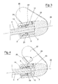
figure 3 is a longitudinal section view of the device offigure 1 in a condition in which the rod is coupled to the body and the retaining element is in a second operating position; -
figure 4 is a similar view tofigure 3 in a condition in which the retaining element is brought into a first operating position in order to enable removal of the rod from the body; -
figure 5 is a perspective exploded view of a second embodiment of the mechanical interconnection device of the present invention; -
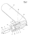
figure 6 is a longitudinal section view of the device offigure 5 in a condition in which the rod is completely inserted into the handle body. - With reference to the accompanying figures of the drawings, a mechanical interconnecting device with a stem for mounting door handles of the present invention is denoted in its entirety by reference number 1.
- In a first embodiment, the device 1 comprises a
body 2 provided with a coupling opening 3 destined to enable insertion of arod 4 internally thereof, in aninsertion sense 26a along aninsertion direction 26, for coupling thebody 2 to therod 4. The device 1 further comprises aretaining element 5 provided with a through-opening 6 having aprofile 7 destined to be crossed by therod 4. In greater detail, theretaining element 5 is housed in aseating 8 afforded in a portion of thecoupling opening 3 of thebody 2 configured such as to enable displacement of theretaining element 5 internally of thebody 2. The displacement is made between a first operating position in which theretaining element 5 exhibits the through-opening 6 arranged such as to enable passage of thestem 4 and a second operating position in which at least a portion of theprofile 7 of the through-opening 6 interferes with therod 4 in order to prevent extraction thereof from thebody 2. - In the preferred embodiment at least two portions of profile 7 (an upper and a lower portion) enter into contact with the surface of the
stem 4 in the second operating position. In the first operating position the through-opening 6 preferably exhibits a projection on the plane that is perpendicular to the insertion direction having at least a predetermined dimension which is destined to enable passage of therod 4, while in the second position the dimension of the projection of the coupling opening on the plane is smaller than the predetermined dimension. - The
retaining element 5 is advantageously arranged perpendicular to the insertion direction of therod 4 when in the first operating position and is instead inclined when in the second operating position. Theretaining element 5 is displaceable from the second operating position to the first operating position by effect of the thrust exerted by therod 4 during the insertion of thebody 2 and is displaceable towards the second operation position by effect of the thrust exerted by therod 4 in extraction from thecoupling opening 3. - In the embodiments illustrated in the figures, the
body 2 further comprises aclosing element 9 destined to contain theretaining element 5 internally of thebody 2 and provided with acentral opening 10 which enables therod 4 to cross. Theclosing element 9 exhibits a firstexternal surface 12 and asecond rest surface 13 facing towards the inside of theseating 8 and complementarily-inclined with respect to the inclination assumed by theretaining element 5 when in the second operating position. - In this way, a
first rest surface 11 on theseating 8 is defined at thecoupling opening 3, defining the first operating position of theretaining element 5, while thesecond rest surface 13 of theclosing element 9 defines, for theretaining element 5, the second operating position and is inclined with respect to thefirst rest surface 11. - The
body 2 preferably further comprises astop ring 14, for example a common seeger ring, destined to insert in a seating afforded in thebody 2 and to maintain theclosing element 9 internally of thebody 2 and to prevent exit thereof, especially during the stages of insertion and extraction of therod 4 from thebody 2 of the device 1. - The
body 2 advantageously further comprises anelastic element 15 housed internally thereof for pushing theretaining element 5 towards the second operating position. Theelastic element 15 is preferably positioned at anaxial slot 16 in thebody 2. With reference tofigures 3 and 4 , theelastic element 15 is positioned such as not to interfere with the passage of therod 4. It extends from theseating 8 towards theclosing element 9 and acts in an axial direction. - In the illustrated embodiments the
elastic element 15 is a helix spring housed at afirst end 18a in ahole 27 afforded in thebody 2 and having asecond end 18b which is operatively active on theretaining element 5. Alternatively theelastic element 15 could be constituted by a different element suitable for the purpose. - As illustrated in
figure 1 , theretaining element 5 is substantially plate-shaped and exhibits an activatingportion 17 which is preferably constituted by a radially-extending protuberance. The activatingportion 17 rests on thesecond end 18b of theelastic element 15, as can be seen infigure 2 . In the passage between an operating position and the other, theretaining element 5 moves internally of theseating 8 and the activatingportion 17 slides internally of theaxial slot 16. - The
body 2 advantageously affords a furtheraxial slot 19 for housing apin 20 that is solidly constrained to theclosing element 9. Thepin 20 guarantees correct orientation of the closing element 9 (e.g. the correct angular position of the closing element 9) and thesecond rest surface 13 on which theretaining element 5 rests in the second operating position. - In the second position, the
retaining element 5 is advantageously inclined at an angle comprised between 3° and 30°, and preferably between 5° and 10°, with respect to the first operating position. - In the first embodiment, the
body 2 is insertable in acavity 21 afforded in ahandle 22. Thebody 2 is further fastenable to thehandle 22 by means of afastening screw 23. - As is better illustrated in
figure 4 , thebody 2 is additionally provided with an activatingopening 24 destined to enable displacement of theretaining element 5 from the second to the first operating position, overcoming the resistance of theelastic element 15. The activatingportion 17 is activatable through the activatingopening 24 by means of a specially-shaped key 25 (visible infigure 4 , in which it is shaped such as to displace the activatingportion 17 following a rotation thereof), in order to enable extraction of therod 4 inserted in thebody 2 from thebody 2 itself. In the first embodiment the activatingopening 24 is defined by a portion of theslot 16 and is further associated and aligned to an additional activating opening 24' defined in thehandle 22. - A further embodiment of the present invention, illustrated in
figures 5 and 6 , comprises thebody 2 of the device 1 fashioned in a single piece from thehandle 22, and therefore integral there-with. In this case thefastening screw 23 is not present, as thebody 2 is already solidly constrained to thehandle 22. The functioning is entirely similar to what is described for the first embodiment. - In this case the activating
opening 24 is defined directly in thebody 2, solidly with thehandle 22, and an additional activating opening 24' is not required. - In the figures, the
rod 4 is represented solidly associated to asecond handle 28. The shape of the section of therod 4 and the cited openings can be any, for example square, rectangular, circular, elliptical, triangular, polygonal, etc. - The invention further relates to a method for rapid mounting of a door handle by means of the above-described device, comprising steps of mounting the
rod 4 for door handles to a door, inserting a free end of therod 4 in thecoupling opening 3, pushing thestem 4 internally of thebody 2 such as to displace, by means of therod 4, the retainingelement 5 from the second operating position to the first operating position and pushing the free end of therod 4 through the through-opening 6 of the retainingelement 5. - In the functioning of the device 1 the
rod 4 is inserted in thecoupling opening 3, and pushed internally of thebody 2, such as to displace the retainingelement 5 from the second operating position to the first operating position. When therod 4 is inserted in thebody 2, the retainingelement 5 is newly pushed towards the second operating position by theelastic element 15, maintaining therod 4 coupled with thebody 2. - The retaining
element 5 prevents extraction of therod 4 from thebody 2 as the extraction force exerted in anextraction direction 26b opposite theinsertion direction 26a determines a push on the retainingelement 5 towards the second operating position and a consequent interference with therod 4, which remains in a coupling with thebody 2. The greater the extraction force of therod 4, the greater the push exerted by the retainingelement 5 on therod 4. - To enable removal of the
rod 4, it is sufficient to act, for example by means of the key 25, on the activatingportion 17 of the retainingelement 5 in order to displace the retainingelement 5 towards the first operating position and thus free therod 4, enabling it to be extracted from thecoupling opening 3. - The present invention attains the set aims, obviating the drawbacks in the prior art.
- Firstly, the device is structurally simple and thus involves only contained costs.
- Further, as above-specified, the assembly or deassembly of the handle is done following a simple push of the rod in the coupling opening, and is thus simple and rapid.
- Consequently, the mounting operations are particularly fast. Further, also the removal of the handle is very simple and rapid.
Claims (10)
- A device (1) for mechanical interconnection to a rod (4) for door handles, comprising:a body (2) provided with a coupling opening (3) designed to enable insertion of a rod (4) internally thereof along an insertion direction such as to couple the body (2) with the rod (4);a retaining element (5) provided with a through-opening (6) having a profile (7) destined to be crossed by the rod (4), the retaining element (5) being housed in a seating (8) obtained in a portion of the coupling opening (3) of the body (2), the seating (8) being configured such as to enable movement of the retaining element (5) internally of the body (2), at least between a first operating position in which the retaining element (5) exhibits the through-opening (6) arranged such as to enable the passage of the rod (4), and at least a second operating position in which at least a portion of the profile (7) of the through-opening (6) interferes with the rod (4) such as to prevent extraction thereof from the body (2).
- The device according to the preceding claim, wherein the retaining element (5) can be moved from the second operating position to the first operating position as a result of the thrust exerted by the rod (4) when inserted into the body (2), and it can be shifted towards the second operating position as a result of the thrust exerted by the rod (4) during extraction from the coupling opening (3).
- The device according to any one of the preceding claims, wherein in the first operating position the through-opening (6) has a projection, on a plane that is perpendicular to the insertion direction, having at least a predetermined dimension destined to enable passage of the rod (4), and in the second operating position the dimension of the projection of the through-opening (6) on the plane is smaller than the predetermined dimension.
- The device according to any one of the preceding claims, wherein the retaining element (5) has a substantially plate-like conformation.
- The device according to any one of the preceding claims, wherein the retaining element (5) is arranged perpendicular to the insertion direction (26) in the first operating position, and in the second operating position is arranged tilted with respect to the insertion direction (26), and wherein it exhibits, at the seating (8), a first supporting surface (11) for the retaining element (5) defining the first operating position, and a second supporting surface (13) for the retaining element (5) defining the second operating position and tilted with respect to the first supporting surface (11).
- The device according to any one of the preceding claims, wherein the retaining element (5) is tilted in the second operating position of an angle ranging from 3° to 30°, and preferably from 5° to 10°, with respect to the first operating position.
- The device according to any one of the preceding claims, characterized in that it further comprises an elastic element (15) housed in the body (2) for pushing the retaining element (5) towards the second operating position.
- The device according to any one of the preceding claims, wherein the body (2) is provided with an activating opening (24) destined to enable the movement of the retaining element (5) between the second and the first operating position, and the retaining element (5) is provided with an activating portion (17) which can be actuated through the activating opening (24), such as to enable extraction of the rod (4) inserted in the body (2) from the body (2).
- A rapid assembly device for a door handle, comprising a device for interconnection according to any one of the preceding claims, fastened to the handle (22), and a rod (4) which can be coupled with the device for interconnection.
- A method for rapid assembly of a door handle by means of a device according to any one of the preceding claims, comprising the following steps:mounting a rod (4) for door handles to a door,inserting a free end of the rod (4) into the coupling opening (3) pushing the rod (4) inside the body (2) such as to move, by means of the rod (4), the retaining element (5) from the second operating position into the first operating position,pushing the free end of the rod (4) through the through-opening (6) of the retaining element (5).
Applications Claiming Priority (1)
| Application Number | Priority Date | Filing Date | Title |
|---|---|---|---|
| IT000072A ITBS20090072A1 (en) | 2009-04-17 | 2009-04-17 | MECHANICAL INTERCONNECTION DEVICE WITH A STEM FOR DOOR HANDLES |
Publications (1)
| Publication Number | Publication Date |
|---|---|
| EP2241704A1 true EP2241704A1 (en) | 2010-10-20 |
Family
ID=41280434
Family Applications (1)
| Application Number | Title | Priority Date | Filing Date |
|---|---|---|---|
| EP20100160068 Withdrawn EP2241704A1 (en) | 2009-04-17 | 2010-04-15 | Device for mechanical interconnection to a square axis for door handles |
Country Status (2)
| Country | Link |
|---|---|
| EP (1) | EP2241704A1 (en) |
| IT (1) | ITBS20090072A1 (en) |
Cited By (12)
| Publication number | Priority date | Publication date | Assignee | Title |
|---|---|---|---|---|
| JP2012067497A (en) * | 2010-09-22 | 2012-04-05 | West Inx Ltd | Connection structure of door handle |
| NL2008525C2 (en) * | 2012-03-22 | 2013-09-25 | Artitec B V | CONTROL PANEL FOR A PANEL, COMPOSITION OF TWO CONTROLS AND A METHOD OF CLAMPING-RESISTANT AGAINST A PANEL POSITIONING THE CONTROL PANEL. |
| WO2014131522A1 (en) * | 2013-02-28 | 2014-09-04 | Almar S.P.A. | Actuating handle |
| JP2015071906A (en) * | 2013-10-03 | 2015-04-16 | 株式会社竹内製作所 | Handle for door |
| EP3202999A1 (en) * | 2016-02-04 | 2017-08-09 | Hoppe Ag | Actuating handle and insert member for an actuating handle |
| EP3480394A1 (en) * | 2017-11-06 | 2019-05-08 | MasterLAB S.r.l. - Unipersonale | Moving device for moving manoeuvring or closing members of a window or door |
| WO2019229260A1 (en) | 2018-06-01 | 2019-12-05 | Bronze Alu | Window and door handle for quick, tool-free assembly and disassembly |
| WO2020088933A1 (en) * | 2018-10-30 | 2020-05-07 | Fischerwerke Gmbh & Co. Kg | Fastening element for mounting handles |
| CN111295492A (en) * | 2017-11-03 | 2020-06-16 | 帕斯卡·勒克莱克 | Manual controls for opening and closing door or window locks |
| CN111295493A (en) * | 2017-11-03 | 2020-06-16 | 帕斯卡·勒克莱克 | Manual controls for opening and closing door or window locks |
| IT201900003755A1 (en) * | 2019-03-14 | 2020-09-14 | C F M G S R L | Automatic tensioner and method of realization of the same |
| EP4253700B1 (en) | 2018-11-22 | 2025-06-04 | Griffwerk GmbH | Door fitting having a handle which can be locked on one side |
Citations (4)
| Publication number | Priority date | Publication date | Assignee | Title |
|---|---|---|---|---|
| US708336A (en) * | 1902-06-10 | 1902-09-02 | Yale & Towne Mfg Co | Door-knob. |
| JPH08232511A (en) * | 1995-02-28 | 1996-09-10 | Nagasawa Seisakusho:Kk | Coupling structure of lever handle for door |
| JP2003097103A (en) * | 2001-09-27 | 2003-04-03 | Nishi Seisakusho:Kk | Door handle connection structure |
| DE202005017497U1 (en) * | 2005-11-07 | 2007-03-15 | Hoppe Ag | Actuating handle |
-
2009
- 2009-04-17 IT IT000072A patent/ITBS20090072A1/en unknown
-
2010
- 2010-04-15 EP EP20100160068 patent/EP2241704A1/en not_active Withdrawn
Patent Citations (4)
| Publication number | Priority date | Publication date | Assignee | Title |
|---|---|---|---|---|
| US708336A (en) * | 1902-06-10 | 1902-09-02 | Yale & Towne Mfg Co | Door-knob. |
| JPH08232511A (en) * | 1995-02-28 | 1996-09-10 | Nagasawa Seisakusho:Kk | Coupling structure of lever handle for door |
| JP2003097103A (en) * | 2001-09-27 | 2003-04-03 | Nishi Seisakusho:Kk | Door handle connection structure |
| DE202005017497U1 (en) * | 2005-11-07 | 2007-03-15 | Hoppe Ag | Actuating handle |
Cited By (17)
| Publication number | Priority date | Publication date | Assignee | Title |
|---|---|---|---|---|
| JP2012067497A (en) * | 2010-09-22 | 2012-04-05 | West Inx Ltd | Connection structure of door handle |
| NL2008525C2 (en) * | 2012-03-22 | 2013-09-25 | Artitec B V | CONTROL PANEL FOR A PANEL, COMPOSITION OF TWO CONTROLS AND A METHOD OF CLAMPING-RESISTANT AGAINST A PANEL POSITIONING THE CONTROL PANEL. |
| WO2014131522A1 (en) * | 2013-02-28 | 2014-09-04 | Almar S.P.A. | Actuating handle |
| RU2598835C1 (en) * | 2013-02-28 | 2016-09-27 | Альмар С.П.А. | Drive handle |
| JP2015071906A (en) * | 2013-10-03 | 2015-04-16 | 株式会社竹内製作所 | Handle for door |
| RU2721044C2 (en) * | 2016-02-04 | 2020-05-15 | Хоппе Аг | Control handle and insert for control handle |
| EP3202999A1 (en) * | 2016-02-04 | 2017-08-09 | Hoppe Ag | Actuating handle and insert member for an actuating handle |
| CN107035228A (en) * | 2016-02-04 | 2017-08-11 | 霍帕股份公司 | Operating handle and insert for operating handle |
| CN111295492A (en) * | 2017-11-03 | 2020-06-16 | 帕斯卡·勒克莱克 | Manual controls for opening and closing door or window locks |
| CN111295493A (en) * | 2017-11-03 | 2020-06-16 | 帕斯卡·勒克莱克 | Manual controls for opening and closing door or window locks |
| CN111295493B (en) * | 2017-11-03 | 2021-10-12 | 帕斯卡·勒克莱克 | Manual control device for a lock for opening and closing a door or window |
| EP3480394A1 (en) * | 2017-11-06 | 2019-05-08 | MasterLAB S.r.l. - Unipersonale | Moving device for moving manoeuvring or closing members of a window or door |
| FR3081902A1 (en) | 2018-06-01 | 2019-12-06 | Bronze Alu | DOOR HANDLE AND WINDOW FOR QUICK ASSEMBLY AND REMOVAL WITHOUT TOOL |
| WO2019229260A1 (en) | 2018-06-01 | 2019-12-05 | Bronze Alu | Window and door handle for quick, tool-free assembly and disassembly |
| WO2020088933A1 (en) * | 2018-10-30 | 2020-05-07 | Fischerwerke Gmbh & Co. Kg | Fastening element for mounting handles |
| EP4253700B1 (en) | 2018-11-22 | 2025-06-04 | Griffwerk GmbH | Door fitting having a handle which can be locked on one side |
| IT201900003755A1 (en) * | 2019-03-14 | 2020-09-14 | C F M G S R L | Automatic tensioner and method of realization of the same |
Also Published As
| Publication number | Publication date |
|---|---|
| ITBS20090072A1 (en) | 2010-10-18 |
Similar Documents
| Publication | Publication Date | Title |
|---|---|---|
| EP2241704A1 (en) | Device for mechanical interconnection to a square axis for door handles | |
| EP0460729B1 (en) | Plugged fastening device with snap-action locking for control and/or signalling units | |
| CN109844330B (en) | Connecting device | |
| JP2008008140A (en) | Method for mounting drive assembly for door frame and window frame | |
| KR100826041B1 (en) | Hollow Drill Holder | |
| CN108498170B (en) | Endoscope connection structure of laparoscopic surgery mirror robot | |
| US7679017B1 (en) | Switch structure | |
| CN113431431A (en) | Adapter for mounting a retaining element of a door or window handle | |
| CN105164355A (en) | Rotary lever lock | |
| CN113195849A (en) | Handle assembly for a window or door type opening blade | |
| US8746022B2 (en) | Pull-up latch mechanism | |
| CA2689829A1 (en) | Actuating lever | |
| CN105350843A (en) | Fixing mechanism for an insert member in a door handle assembly | |
| KR20100125066A (en) | Jig device | |
| US9177731B2 (en) | Flexible cable assembly for high-power switch gear | |
| US11879493B2 (en) | Split nut | |
| US9177732B2 (en) | Flexible cable assembly with improved manufacturability | |
| EP3023566A1 (en) | Diagonal draw bar structure having micro ventilation function | |
| KR101439242B1 (en) | Lock door lock comprising a display device | |
| EP2299037A1 (en) | Mechanical interconnection device for coupling with an hollow body | |
| JPH08232511A (en) | Coupling structure of lever handle for door | |
| KR200420247Y1 (en) | Door handle lever device for operating Mortis lock | |
| CN112312799B (en) | Drawer and method for mounting rear panel on side frame of drawer | |
| KR101130653B1 (en) | Captive screw | |
| CN113775251A (en) | Handle device and disassembling and assembling method thereof |
Legal Events
| Date | Code | Title | Description |
|---|---|---|---|
| PUAI | Public reference made under article 153(3) epc to a published international application that has entered the european phase |
Free format text: ORIGINAL CODE: 0009012 |
|
| AK | Designated contracting states |
Kind code of ref document: A1 Designated state(s): AT BE BG CH CY CZ DE DK EE ES FI FR GB GR HR HU IE IS IT LI LT LU LV MC MK MT NL NO PL PT RO SE SI SK SM TR |
|
| AX | Request for extension of the european patent |
Extension state: AL BA ME RS |
|
| STAA | Information on the status of an ep patent application or granted ep patent |
Free format text: STATUS: THE APPLICATION IS DEEMED TO BE WITHDRAWN |
|
| 18D | Application deemed to be withdrawn |
Effective date: 20110421 |