EP2243558B1 - Kolben zum Auspressen von Füllsubstanzen - Google Patents
Kolben zum Auspressen von Füllsubstanzen Download PDFInfo
- Publication number
- EP2243558B1 EP2243558B1 EP10003966.8A EP10003966A EP2243558B1 EP 2243558 B1 EP2243558 B1 EP 2243558B1 EP 10003966 A EP10003966 A EP 10003966A EP 2243558 B1 EP2243558 B1 EP 2243558B1
- Authority
- EP
- European Patent Office
- Prior art keywords
- piston
- end wall
- wall
- peripheral
- cartridge
- Prior art date
- Legal status (The legal status is an assumption and is not a legal conclusion. Google has not performed a legal analysis and makes no representation as to the accuracy of the status listed.)
- Not-in-force
Links
- 239000000945 filler Substances 0.000 title description 6
- 230000002093 peripheral effect Effects 0.000 claims description 35
- 239000000126 substance Substances 0.000 claims description 18
- 238000007789 sealing Methods 0.000 claims description 14
- 230000007704 transition Effects 0.000 claims description 14
- 239000004033 plastic Substances 0.000 claims description 10
- 229920003023 plastic Polymers 0.000 claims description 10
- 239000000463 material Substances 0.000 claims description 7
- 239000004743 Polypropylene Substances 0.000 claims description 4
- 229920001903 high density polyethylene Polymers 0.000 claims description 4
- 239000004700 high-density polyethylene Substances 0.000 claims description 4
- 229920001684 low density polyethylene Polymers 0.000 claims description 4
- 239000004702 low-density polyethylene Substances 0.000 claims description 4
- 229920001155 polypropylene Polymers 0.000 claims description 4
- -1 Polypropylene Polymers 0.000 claims description 2
- 230000002787 reinforcement Effects 0.000 claims 8
- 239000012858 resilient material Substances 0.000 claims 1
- 238000001125 extrusion Methods 0.000 description 11
- 239000013013 elastic material Substances 0.000 description 4
- 239000003351 stiffener Substances 0.000 description 4
- 230000009471 action Effects 0.000 description 3
- 230000000694 effects Effects 0.000 description 3
- 238000000034 method Methods 0.000 description 3
- 230000008569 process Effects 0.000 description 3
- 238000007373 indentation Methods 0.000 description 2
- 238000010521 absorption reaction Methods 0.000 description 1
- 230000015572 biosynthetic process Effects 0.000 description 1
- 230000008859 change Effects 0.000 description 1
- 238000006243 chemical reaction Methods 0.000 description 1
- 229920000098 polyolefin Polymers 0.000 description 1
- 229920001296 polysiloxane Polymers 0.000 description 1
- 230000009467 reduction Effects 0.000 description 1
- XLYOFNOQVPJJNP-UHFFFAOYSA-N water Substances O XLYOFNOQVPJJNP-UHFFFAOYSA-N 0.000 description 1
Images


Classifications
-
- B—PERFORMING OPERATIONS; TRANSPORTING
- B05—SPRAYING OR ATOMISING IN GENERAL; APPLYING FLUENT MATERIALS TO SURFACES, IN GENERAL
- B05C—APPARATUS FOR APPLYING FLUENT MATERIALS TO SURFACES, IN GENERAL
- B05C17/00—Hand tools or apparatus using hand held tools, for applying liquids or other fluent materials to, for spreading applied liquids or other fluent materials on, or for partially removing applied liquids or other fluent materials from, surfaces
- B05C17/005—Hand tools or apparatus using hand held tools, for applying liquids or other fluent materials to, for spreading applied liquids or other fluent materials on, or for partially removing applied liquids or other fluent materials from, surfaces for discharging material from a reservoir or container located in or on the hand tool through an outlet orifice by pressure without using surface contacting members like pads or brushes
- B05C17/00576—Hand tools or apparatus using hand held tools, for applying liquids or other fluent materials to, for spreading applied liquids or other fluent materials on, or for partially removing applied liquids or other fluent materials from, surfaces for discharging material from a reservoir or container located in or on the hand tool through an outlet orifice by pressure without using surface contacting members like pads or brushes characterised by the construction of a piston as pressure exerting means, or of the co-operating container
-
- B—PERFORMING OPERATIONS; TRANSPORTING
- B05—SPRAYING OR ATOMISING IN GENERAL; APPLYING FLUENT MATERIALS TO SURFACES, IN GENERAL
- B05C—APPARATUS FOR APPLYING FLUENT MATERIALS TO SURFACES, IN GENERAL
- B05C17/00—Hand tools or apparatus using hand held tools, for applying liquids or other fluent materials to, for spreading applied liquids or other fluent materials on, or for partially removing applied liquids or other fluent materials from, surfaces
- B05C17/005—Hand tools or apparatus using hand held tools, for applying liquids or other fluent materials to, for spreading applied liquids or other fluent materials on, or for partially removing applied liquids or other fluent materials from, surfaces for discharging material from a reservoir or container located in or on the hand tool through an outlet orifice by pressure without using surface contacting members like pads or brushes
- B05C17/01—Hand tools or apparatus using hand held tools, for applying liquids or other fluent materials to, for spreading applied liquids or other fluent materials on, or for partially removing applied liquids or other fluent materials from, surfaces for discharging material from a reservoir or container located in or on the hand tool through an outlet orifice by pressure without using surface contacting members like pads or brushes with manually mechanically or electrically actuated piston or the like
-
- B—PERFORMING OPERATIONS; TRANSPORTING
- B05—SPRAYING OR ATOMISING IN GENERAL; APPLYING FLUENT MATERIALS TO SURFACES, IN GENERAL
- B05C—APPARATUS FOR APPLYING FLUENT MATERIALS TO SURFACES, IN GENERAL
- B05C17/00—Hand tools or apparatus using hand held tools, for applying liquids or other fluent materials to, for spreading applied liquids or other fluent materials on, or for partially removing applied liquids or other fluent materials from, surfaces
- B05C17/005—Hand tools or apparatus using hand held tools, for applying liquids or other fluent materials to, for spreading applied liquids or other fluent materials on, or for partially removing applied liquids or other fluent materials from, surfaces for discharging material from a reservoir or container located in or on the hand tool through an outlet orifice by pressure without using surface contacting members like pads or brushes
- B05C17/015—Hand tools or apparatus using hand held tools, for applying liquids or other fluent materials to, for spreading applied liquids or other fluent materials on, or for partially removing applied liquids or other fluent materials from, surfaces for discharging material from a reservoir or container located in or on the hand tool through an outlet orifice by pressure without using surface contacting members like pads or brushes with pneumatically or hydraulically actuated piston or the like
Definitions
- the invention relates to a piston made of elastic material for pressing filling substances from a container under pressure load, wherein the piston has a piston peripheral wall and an end wall, and wherein the end wall in the unloaded state has a curved in the extrusion direction.
- EP0153669A2 and DE2629682 A1 are known and come in connection with a designed as a cartridge cylindrical container for use. Such a cartridge is typically inserted into a cartridge gun and used for grouting and sealing, for example, wet rooms. That for this Required tool comprises a filled with the joint material plastic cartridge, at one end of a so-called dome can escape over the means of a screw-nozzle, for example, the joint material, if at its other, open end on the piston, a corresponding pressure on the joint material or the filling substance is exerted in the cartridge. To squeeze out the filler, the piston is usually moved mechanically by a sliding punch. The piston performs a straight line movement from the open end of the cartridge to the end with the dome and the plugged, snapped or screwed nozzle out.
- a piston of the aforementioned type wherein under pressure load, the end wall is deformed into a state of lesser curvature, and that the end wall is radially expanded at least in a transition region from the end wall to the piston peripheral wall.
- This radial expansion which occurs under the pressure load of the Auspressvorgangs, has the consequence that significantly less residues of the filler on the inside of the container (the container, for example, the shape of a plastic cartridge ) stay behind.
- the entire filling substance eg silicone
- the residue-free pressing allows a cleaner and more economical use of filled cartridges, especially in the professional field of application.
- the widening of the piston in the radial direction is a consequence of the elastic deformability of the piston, in particular a consequence of the elastic deformability of the curved end wall.
- the piston is made of an elastic material, typically a plastic.
- the designed as a cartridge container is also usually made of an elastic plastic, so that at a relatively strong radial expansion of the piston according to the invention, the container can yield to a certain extent, without causing wedging of the piston and container.
- the container is typically cylindrical, in particular circular cylindrical.
- the piston peripheral wall is generally cylindrical, in particular circular cylindrical.
- the tank and the piston can also have other cross sections such as oval, angular (any polygons) or combinations thereof.
- Examples of a curvature in the context of the invention are any elevations of the end wall in the extrusion direction. Such elevations arise, for example, from rounding profiles, which were rotated about a central axis of the piston.
- the piston according to the invention is generally a rotationally symmetrical component.
- the piston according to the invention is characterized in that an at least partially circumferential portion is formed on the piston circumferential wall, which has a smaller wall thickness in comparison to the remaining piston peripheral wall.
- the piston peripheral wall is partially weakened, creating a kind of revolving, but at least partially revolving, hinge.
- a hinge ring hinge or film hinge
- the peripheral portion of the piston peripheral wall is able to better follow the radial expansion of the end wall, as it has a smaller wall thickness and thus the expansion less opposes resistance, as a piston peripheral wall with the same wall thickness.
- the section or the ring hinge can also be designed, for example, as a notch, groove, indentation, recess or groove.
- a series of punctiform holes in the piston perimeter wall may also represent the circumferential section.
- a sufficient height of the circumferential section (eg 1 ⁇ 4 of the piston height) ensures a good hinge effect.
- the at least partially circumferential portion may also be formed on a piston made of tough elastic and / or rubber-elastic material whose end face is divided into a central portion and an annular outer portion, wherein the central portion is dimensionally stable and opposite radially outward forces stiffened outer section expands under pressure.
- the central portion may be connected to the outer portion via a first connection point and the outer portion may be connected to the piston peripheral wall via a second connection point, wherein the first connection point is set back in the direction of extrusion of the piston relative to the second connection point.
- the outer portion and the central portion of such a piston may form an annular or a plurality of annular portions recess, wherein the recess comprises a coaxial with the piston peripheral wall disposed first partial surface and a second partial surface connected to the second, forming the outer portion, part surface, and wherein the second partial surface expands in the extrusion direction and in the radial direction and ends at the piston peripheral wall.
- the portion of lesser wall thickness directly adjoins the transition region from the end wall to the piston peripheral wall.
- the hinge action of the section and also the radial expansion advantageously remain limited to the immediate transition area.
- the remaining part of the piston, in particular the piston peripheral wall then continues to form a stable unit.
- a further preferred embodiment is characterized in that at least one sealing edge is formed at the transition region from the end wall to the piston peripheral wall.
- the sealing edge slides during the Auspressvorgangs on the inside of the generally cylindrical container along. The formation of a defined sealing edge favors a clean, complete and thus residue-free extrusion of the filling substance from the cylindrical container or the cartridge.
- piston circumferential wall has at least one sealing lip on its outside is particularly preferred. Then an increased security is given in an advantageous manner, that also at a possibly injured sealing edge, the filling substance can be pressed out of the cylindrical container or the cartridge as far as possible without residue.
- the piston is compressed air.
- the piston is versatile with the cylindrical container. In particular, automation on a larger scale in professional applications is possible.
- Another preferred embodiment is characterized in that the piston is pressure-loadable by a mechanically displaceable punch.
- Mechanically displaceable punches allow in a very simple manner control over the Auspressvorgang the filler.
- stiffening elements are formed on the piston in the transition region from the end wall to the piston circumferential wall.
- the stiffening elements are integrally formed both on the end wall and on the piston peripheral wall.
- the stiffening elements are usually formed on the piston inside as ribs. The stiffening elements formed in this way can serve as contact points for a punch for mechanical extrusion of the filling substance.
- the degree of stiffening of the stiffening elements in the radial direction increases toward the piston outer circumference.
- Such formed pistons have a stiffening geometry, by which the piston in the piston circumferential direction can be widened easily, while the circumferential stresses are minimized in the piston.
- Stiffening degree is understood to mean the number of stiffening elements per surface.
- An increasing in the radial direction Degree of stiffening can be realized, for example, by the fact that radially extending ribs branch more and more frequently towards the outer circumference of the piston, and thus the number of ribs per unit area in the vicinity of the transitional region from the piston circumferential wall to the end wall is increased in comparison to the end wall center.
- stiffening means are formed on the end wall, which adjoin the stiffening elements, wherein the stiffening means extend in the direction of the end wall center.
- the stiffening prevent a purely local deformation of the end wall (eg deformation by dents) and give the end wall sufficient stability to forward the contact pressure of the piston to the container can.
- a piston expansion is thus possible even with small end wall deformations. Due to the widening possibility in the circumferential direction during expansion no higher hoop stresses occur in the piston.
- the stiffening means are typically formed on the inside of the end wall.
- an additional stiffening on the end wall is formed, wherein the additional stiffening is formed in the region of the center of the end wall.
- the additional stiffening is not usually formed on the other stiffening and / or stiffening elements, but mounted isolated on the end wall. Such stiffening may e.g. have the shape of a hollow cylinder.
- the additional stiffening is usually formed on the inside of the end wall.
- stiffeners can also be formed on the outside of the end wall.
- the stiffeners protrude into the space bounded by the piston and the container (cartridge).
- a stiffener may be formed, for example, as a rib, web or the like.
- stiffening is also understood to mean a local increase in material thickness or a local recess reduction in the material thickness of a piston wall.
- the piston is made of low density polyethylene (LDPE), high density polyethylene (HDPE), polypropylene (PP) or another plastic.
- LDPE low density polyethylene
- HDPE high density polyethylene
- PP polypropylene
- the piston is given many advantageous properties, e.g. a high resistance through high toughness and elongation at break values as well as a good sliding behavior with at the same time very low water absorption. The latter is particularly advantageous if an unwanted reaction of the filler is to be avoided by contact with the piston.
- a piston for storing and pressing of filling substances in the container, in particular in a cartridge, is used.
- the storage and squeezing of filling substances is allowed, which are located in the interior, which is limited by the piston and the container.
- a piston can be used as a soft or hard piston or a piston made of a combination of tough and rubber-elastic plastics together with known cartridges.
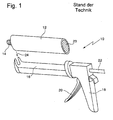
- FIG. 1 is denoted by 10 a cartridge gun into which a cartridge 12 with dome 14 can be inserted.
- the cartridge gun 10 has for this purpose an elongated guide 16, to which a handle 18 connects via the means of a lever 20 a punch with a punch rod 22 via the open end 23 of the cartridge 12 in the cartridge 12 can be moved linearly.
- the cartridge 12 is closed at the open end 23 via a piston, not shown in the figure.
- the piston can be pushed into the cartridge 12 via the punch formed at one end of the punch rod 22 after the cartridge 12 has been inserted in the direction of the arrow 24 into the cartridge gun 10.
- About the piston stored in the cartridge 12 filling substance, for example via the dome 14 and a screwed onto the dome 14, pressed out nozzle, not shown, and then further processed.
- the FIG. 2 shows a piston 30 in cross-section, wherein the piston 30 comprises a cylindrical piston peripheral wall 32 and a bulging in the extrusion direction 34 end wall 36.
- the piston 30 comprises a cylindrical piston peripheral wall 32 and a bulging in the extrusion direction 34 end wall 36.
- stiffening elements 38 are formed on the piston.
- the stiffening elements 38 are integrally formed with a web side on the end wall 36 and with another web side to the cylindrical piston peripheral wall 32.
- stiffening means 40 are integrally formed on the end wall 36, wherein the stiffening means 40 are also formed as ribs.
- the extent of the stiffening elements 38 in the direction of the end wall center is limited radially (in the FIG. 2 to about 35% of the piston radius R).
- the stiffening elements 38 can serve to bear a stamp, with which the pressure for pressing the filling material is exerted on the piston 30.
- the piston 30 is a rotationally symmetrical part made of plastic.
- the end wall 36 has on its outer side 42 in its center a conical tip 44.
- the transition from the end wall 36 to the piston peripheral wall 32 (transition region 37) is defined on the outside by a sealing edge 46. It is in the inserted into the cartridge state directly on the inside of the cartridge. Immediately adjacent the sealing edge 46, on the outer side 48 of the piston perimeter wall 32, there is a portion 50 having a reduced wall thickness (e.g., half wall thickness of the remaining piston perimeter wall 32). The section 50 has rounded transitions 52 at its edges. Furthermore, 32 sealing lips 54,56 are formed on the outer side 48 of the piston peripheral wall.
- the piston 30 from the FIG. 2 is shown in unloaded condition. That is, the end wall 32 has its usual, the unloaded state corresponding curvature.
- FIG. 3 shows a side view of the piston 30 from the FIG. 2 ,
- the dome-like shape of the curved end wall 36 can be seen.
- This curvature also corresponds to the unloaded state of the piston 30 in the cartridge.
- the portion 50 on the piston peripheral wall 32 can be seen, which develops a hinge action during a pressure load of the piston 30 during a Auspressvorgangs.
- the FIG. 4 shows the piston 30 in the loaded state.
- This state is characterized by a pushed back (pushed back in the direction of arrow 60) end wall 36.
- the pushed-back state of the end wall 36 is expressed in a reduced curvature (larger radius of curvature) of the end wall 36 in comparison to the curvature of the end wall 36 from the FIGS. 2 and 3 .
- the pushing back of the end wall 36 in the loaded state also has the consequence that the end wall 36 expands or increases in the radial direction (see arrow directions 62).
- the sealing edge 46 is increasingly moved in the radial directions 62 and in the case that the piston 30 is inserted into the cartridge, pressed to the inside of the cartridge (cartridge not shown).
- a widening in the radial direction 62 is facilitated by the portion 50. Due to the reduced wall thickness in the region of the section 50, the section 50 assumes a kind of hinge action, which manifests itself in a lateral opening of the section 50 during the widening of the end wall 36.
- FIG. 5 shows a plan view of the inside of the piston 30. It is thus the course of the stiffening elements 38 and the stiffening means 40 on the inside of the end wall 36 can be seen. Representing the entire outer region of the end wall 36, the course of the stiffening elements 38 is shown in dashed area 68.
- the stiffening elements 38 (shown here as webs or ribs) branch increasingly towards the outer edge of the end wall 36. As a result, an increasing stiffening of the end wall 36 in the radial direction 62 (from the center of the end wall 36 to its outer circumference or edge) is achieved (increasing degree of stiffening).
- the stiffening means 40 In the inner region 70 of the end wall 36 (indicated by the dot-dashed circle), however, only the radially extending stiffening means 40 are formed.
- the stiffening means 40 in contrast to the stiffening elements 38 no branches.
- the end wall 38 is thus stiffened in its inner region such that the end wall 36 in the loaded state (during squeezing) withstand the pressure and does not give way locally by kinking or buckling or, for example, "folds".
- the stiffening elements 38 stabilize the outer region of the end wall 36 so that it allows the expansion of the piston 30 without the outer region of the end wall 36 entering or otherwise being damaged.
- the outer region of the end wall 36 and in particular the stiffening elements 38 continue to serve the plant of a punch or slider for moving the piston 30 in the cartridge.
- the invention relates to a piston 30 made of elastic material for pressing filling substances from a container such as a cartridge 12 under pressure load, wherein the piston 30 has a piston peripheral wall 32 and an end wall 36, wherein the end wall 36 in the unloaded state has a bulge in the extrusion direction wherein the end wall 36 is deformable under pressure load in a state of lesser curvature, and wherein the end wall 36 is radially expanded.
- the widening of the end wall 36 has an increased sealing effect of the piston 30 relative to the cartridge 12 for. Thus, undesirable residues on the inner surface of the cartridge 12 are prevented.
Landscapes
- Engineering & Computer Science (AREA)
- Mechanical Engineering (AREA)
- Coating Apparatus (AREA)
- Containers And Packaging Bodies Having A Special Means To Remove Contents (AREA)
- Pistons, Piston Rings, And Cylinders (AREA)
Priority Applications (1)
| Application Number | Priority Date | Filing Date | Title |
|---|---|---|---|
| PL10003966T PL2243558T3 (pl) | 2009-04-20 | 2010-04-15 | Tłok do wyciskania substancji wypełniających |
Applications Claiming Priority (1)
| Application Number | Priority Date | Filing Date | Title |
|---|---|---|---|
| DE202009005745U DE202009005745U1 (de) | 2009-04-20 | 2009-04-20 | Kolben zum Auspressen von Füllsubstanzen |
Publications (3)
| Publication Number | Publication Date |
|---|---|
| EP2243558A2 EP2243558A2 (de) | 2010-10-27 |
| EP2243558A3 EP2243558A3 (de) | 2012-12-26 |
| EP2243558B1 true EP2243558B1 (de) | 2014-06-04 |
Family
ID=40822574
Family Applications (1)
| Application Number | Title | Priority Date | Filing Date |
|---|---|---|---|
| EP10003966.8A Not-in-force EP2243558B1 (de) | 2009-04-20 | 2010-04-15 | Kolben zum Auspressen von Füllsubstanzen |
Country Status (3)
| Country | Link |
|---|---|
| EP (1) | EP2243558B1 (pl) |
| DE (1) | DE202009005745U1 (pl) |
| PL (1) | PL2243558T3 (pl) |
Families Citing this family (1)
| Publication number | Priority date | Publication date | Assignee | Title |
|---|---|---|---|---|
| DE202009013792U1 (de) | 2009-10-09 | 2010-02-18 | Gfv Verschlusstechnik Gmbh & Co. Kg | Kolben zum Auspressen von Füllsubstanzen |
Family Cites Families (3)
| Publication number | Priority date | Publication date | Assignee | Title |
|---|---|---|---|---|
| DE2034047C2 (de) * | 1970-07-09 | 1972-03-30 | Alfred Fischbach KG Kunststoff-Spritzgußwerk, 5252 Ründeroth | Als Ausdrückkolben für plastische Masse dienender Verschluss aus elastischem Werkstoff für einen hohlzylindrischen Strangpressbehälter |
| DE2629682C3 (de) * | 1976-07-01 | 1979-11-08 | Niels Skibby Bay-Schmith (Daenemark) | Ausdrückkolben für hohlzylindrische Strangpreßbehälter, insbesondere Kartusche |
| CH662328A5 (de) * | 1984-02-23 | 1987-09-30 | Arthur Steiger | Verschiebbarer napfboden fuer kartusche zum ausdruecken von pasten. |
-
2009
- 2009-04-20 DE DE202009005745U patent/DE202009005745U1/de not_active Expired - Lifetime
-
2010
- 2010-04-15 EP EP10003966.8A patent/EP2243558B1/de not_active Not-in-force
- 2010-04-15 PL PL10003966T patent/PL2243558T3/pl unknown
Also Published As
| Publication number | Publication date |
|---|---|
| PL2243558T3 (pl) | 2014-11-28 |
| EP2243558A2 (de) | 2010-10-27 |
| EP2243558A3 (de) | 2012-12-26 |
| DE202009005745U1 (de) | 2009-07-02 |
Similar Documents
| Publication | Publication Date | Title |
|---|---|---|
| DE69426607T2 (de) | Balgbehälter | |
| EP1391640B1 (de) | Dichtungsring | |
| EP2539245B1 (de) | Verpackung | |
| EP1871686B1 (de) | Mehrkomponenten-kartusche | |
| EP1500606B1 (de) | Mehrkomponentenkartusche | |
| EP2108599B1 (de) | Kartuschenkolben | |
| DE102015118053A1 (de) | Verschlusseinrichtung für einen Behälter | |
| CH661109A5 (en) | Method for producing a bonded socket-pipe connection and a means, which is suitable for this purpose, for carrying out the method | |
| EP2989019B1 (de) | Behälterverschluss | |
| DE69933920T2 (de) | Rohrdichtung mit einem niedrigen einführungsprofil | |
| DE7029199U (de) | Behaelter mit falzverbindung | |
| EP3741469B1 (de) | Mehrkammerkartusche und verfahren zu ihrer befüllung | |
| DE102008005717A1 (de) | Kraftstofftank mit einem Einfüllrohr und einem Einfüllstutzenkopf | |
| EP2243558B1 (de) | Kolben zum Auspressen von Füllsubstanzen | |
| DE2462123A1 (de) | Selbsttaetiger verschluss fuer einen behaelter mit beim austritt fluessiger, pastoeser oder schaumfoermiger fuellung | |
| DE10207763A1 (de) | Mehrkomponenten-Kartusche | |
| EP1836100B1 (de) | Ringkolben für eine kartusche zum auspressen von pastösen substanzen | |
| DE3107414C2 (de) | Einmalspritze für den medizinischen Gebrauch | |
| DE202008007834U1 (de) | Kolben zum Auspressen von Füllsubstanzen | |
| EP2475915A1 (de) | Ringdichtung für ein schliessglied eines ventils sowie dichtungsanordnung mit einer solchen ringdichtung | |
| WO2024200219A1 (de) | Ressourcenschonende verschlusseinrichtung | |
| WO1999026865A1 (de) | Kartusche für pastöse massen | |
| DE202009013792U1 (de) | Kolben zum Auspressen von Füllsubstanzen | |
| EP2199228B1 (de) | Mehrkomponentenkartusche | |
| DE102006018527A1 (de) | Verschluss für ein Behältnis |
Legal Events
| Date | Code | Title | Description |
|---|---|---|---|
| PUAI | Public reference made under article 153(3) epc to a published international application that has entered the european phase |
Free format text: ORIGINAL CODE: 0009012 |
|
| AK | Designated contracting states |
Kind code of ref document: A2 Designated state(s): AT BE BG CH CY CZ DE DK EE ES FI FR GB GR HR HU IE IS IT LI LT LU LV MC MK MT NL NO PL PT RO SE SI SK SM TR |
|
| AX | Request for extension of the european patent |
Extension state: AL BA ME RS |
|
| PUAL | Search report despatched |
Free format text: ORIGINAL CODE: 0009013 |
|
| AK | Designated contracting states |
Kind code of ref document: A3 Designated state(s): AT BE BG CH CY CZ DE DK EE ES FI FR GB GR HR HU IE IS IT LI LT LU LV MC MK MT NL NO PL PT RO SE SI SK SM TR |
|
| AX | Request for extension of the european patent |
Extension state: AL BA ME RS |
|
| RIC1 | Information provided on ipc code assigned before grant |
Ipc: B65D 83/00 20060101ALI20121116BHEP Ipc: B05C 17/01 20060101ALN20121116BHEP Ipc: B05C 17/005 20060101ALI20121116BHEP Ipc: B05C 17/00 20060101AFI20121116BHEP Ipc: B05C 17/015 20060101ALN20121116BHEP |
|
| 17P | Request for examination filed |
Effective date: 20130614 |
|
| RBV | Designated contracting states (corrected) |
Designated state(s): AT BE BG CH CY CZ DE DK EE ES FI FR GB GR HR HU IE IS IT LI LT LU LV MC MK MT NL NO PL PT RO SE SI SK SM TR |
|
| RIC1 | Information provided on ipc code assigned before grant |
Ipc: B05C 17/005 20060101ALI20131030BHEP Ipc: B05C 17/00 20060101AFI20131030BHEP Ipc: B65D 83/00 20060101ALI20131030BHEP Ipc: B05C 17/01 20060101ALN20131030BHEP Ipc: B05C 17/015 20060101ALN20131030BHEP |
|
| GRAP | Despatch of communication of intention to grant a patent |
Free format text: ORIGINAL CODE: EPIDOSNIGR1 |
|
| INTG | Intention to grant announced |
Effective date: 20131211 |
|
| RIC1 | Information provided on ipc code assigned before grant |
Ipc: B05C 17/00 20060101AFI20131129BHEP Ipc: B05C 17/015 20060101ALN20131129BHEP Ipc: B65D 83/00 20060101ALI20131129BHEP Ipc: B05C 17/005 20060101ALI20131129BHEP Ipc: B05C 17/01 20060101ALN20131129BHEP |
|
| RIN1 | Information on inventor provided before grant (corrected) |
Inventor name: SAIER, HANNS-ULRICH |
|
| GRAS | Grant fee paid |
Free format text: ORIGINAL CODE: EPIDOSNIGR3 |
|
| GRAA | (expected) grant |
Free format text: ORIGINAL CODE: 0009210 |
|
| AK | Designated contracting states |
Kind code of ref document: B1 Designated state(s): AT BE BG CH CY CZ DE DK EE ES FI FR GB GR HR HU IE IS IT LI LT LU LV MC MK MT NL NO PL PT RO SE SI SK SM TR |
|
| REG | Reference to a national code |
Ref country code: GB Ref legal event code: FG4D Free format text: NOT ENGLISH |
|
| REG | Reference to a national code |
Ref country code: CH Ref legal event code: EP |
|
| REG | Reference to a national code |
Ref country code: AT Ref legal event code: REF Ref document number: 670755 Country of ref document: AT Kind code of ref document: T Effective date: 20140615 |
|
| REG | Reference to a national code |
Ref country code: IE Ref legal event code: FG4D Free format text: LANGUAGE OF EP DOCUMENT: GERMAN |
|
| REG | Reference to a national code |
Ref country code: DE Ref legal event code: R096 Ref document number: 502010007085 Country of ref document: DE Effective date: 20140717 |
|
| REG | Reference to a national code |
Ref country code: NL Ref legal event code: T3 |
|
| PG25 | Lapsed in a contracting state [announced via postgrant information from national office to epo] |
Ref country code: LT Free format text: LAPSE BECAUSE OF FAILURE TO SUBMIT A TRANSLATION OF THE DESCRIPTION OR TO PAY THE FEE WITHIN THE PRESCRIBED TIME-LIMIT Effective date: 20140604 Ref country code: FI Free format text: LAPSE BECAUSE OF FAILURE TO SUBMIT A TRANSLATION OF THE DESCRIPTION OR TO PAY THE FEE WITHIN THE PRESCRIBED TIME-LIMIT Effective date: 20140604 Ref country code: NO Free format text: LAPSE BECAUSE OF FAILURE TO SUBMIT A TRANSLATION OF THE DESCRIPTION OR TO PAY THE FEE WITHIN THE PRESCRIBED TIME-LIMIT Effective date: 20140904 Ref country code: GR Free format text: LAPSE BECAUSE OF FAILURE TO SUBMIT A TRANSLATION OF THE DESCRIPTION OR TO PAY THE FEE WITHIN THE PRESCRIBED TIME-LIMIT Effective date: 20140905 Ref country code: CY Free format text: LAPSE BECAUSE OF FAILURE TO SUBMIT A TRANSLATION OF THE DESCRIPTION OR TO PAY THE FEE WITHIN THE PRESCRIBED TIME-LIMIT Effective date: 20140604 |
|
| REG | Reference to a national code |
Ref country code: LT Ref legal event code: MG4D |
|
| PG25 | Lapsed in a contracting state [announced via postgrant information from national office to epo] |
Ref country code: HR Free format text: LAPSE BECAUSE OF FAILURE TO SUBMIT A TRANSLATION OF THE DESCRIPTION OR TO PAY THE FEE WITHIN THE PRESCRIBED TIME-LIMIT Effective date: 20140604 Ref country code: LV Free format text: LAPSE BECAUSE OF FAILURE TO SUBMIT A TRANSLATION OF THE DESCRIPTION OR TO PAY THE FEE WITHIN THE PRESCRIBED TIME-LIMIT Effective date: 20140604 Ref country code: SE Free format text: LAPSE BECAUSE OF FAILURE TO SUBMIT A TRANSLATION OF THE DESCRIPTION OR TO PAY THE FEE WITHIN THE PRESCRIBED TIME-LIMIT Effective date: 20140604 |
|
| REG | Reference to a national code |
Ref country code: PL Ref legal event code: T3 |
|
| PG25 | Lapsed in a contracting state [announced via postgrant information from national office to epo] |
Ref country code: EE Free format text: LAPSE BECAUSE OF FAILURE TO SUBMIT A TRANSLATION OF THE DESCRIPTION OR TO PAY THE FEE WITHIN THE PRESCRIBED TIME-LIMIT Effective date: 20140604 Ref country code: PT Free format text: LAPSE BECAUSE OF FAILURE TO SUBMIT A TRANSLATION OF THE DESCRIPTION OR TO PAY THE FEE WITHIN THE PRESCRIBED TIME-LIMIT Effective date: 20141006 Ref country code: SK Free format text: LAPSE BECAUSE OF FAILURE TO SUBMIT A TRANSLATION OF THE DESCRIPTION OR TO PAY THE FEE WITHIN THE PRESCRIBED TIME-LIMIT Effective date: 20140604 Ref country code: RO Free format text: LAPSE BECAUSE OF FAILURE TO SUBMIT A TRANSLATION OF THE DESCRIPTION OR TO PAY THE FEE WITHIN THE PRESCRIBED TIME-LIMIT Effective date: 20140604 Ref country code: CZ Free format text: LAPSE BECAUSE OF FAILURE TO SUBMIT A TRANSLATION OF THE DESCRIPTION OR TO PAY THE FEE WITHIN THE PRESCRIBED TIME-LIMIT Effective date: 20140604 Ref country code: ES Free format text: LAPSE BECAUSE OF FAILURE TO SUBMIT A TRANSLATION OF THE DESCRIPTION OR TO PAY THE FEE WITHIN THE PRESCRIBED TIME-LIMIT Effective date: 20140604 |
|
| PG25 | Lapsed in a contracting state [announced via postgrant information from national office to epo] |
Ref country code: IS Free format text: LAPSE BECAUSE OF FAILURE TO SUBMIT A TRANSLATION OF THE DESCRIPTION OR TO PAY THE FEE WITHIN THE PRESCRIBED TIME-LIMIT Effective date: 20141004 |
|
| REG | Reference to a national code |
Ref country code: DE Ref legal event code: R097 Ref document number: 502010007085 Country of ref document: DE |
|
| PLBE | No opposition filed within time limit |
Free format text: ORIGINAL CODE: 0009261 |
|
| STAA | Information on the status of an ep patent application or granted ep patent |
Free format text: STATUS: NO OPPOSITION FILED WITHIN TIME LIMIT |
|
| PG25 | Lapsed in a contracting state [announced via postgrant information from national office to epo] |
Ref country code: DK Free format text: LAPSE BECAUSE OF FAILURE TO SUBMIT A TRANSLATION OF THE DESCRIPTION OR TO PAY THE FEE WITHIN THE PRESCRIBED TIME-LIMIT Effective date: 20140604 Ref country code: IT Free format text: LAPSE BECAUSE OF FAILURE TO SUBMIT A TRANSLATION OF THE DESCRIPTION OR TO PAY THE FEE WITHIN THE PRESCRIBED TIME-LIMIT Effective date: 20140604 |
|
| 26N | No opposition filed |
Effective date: 20150305 |
|
| REG | Reference to a national code |
Ref country code: DE Ref legal event code: R097 Ref document number: 502010007085 Country of ref document: DE Effective date: 20150305 |
|
| PG25 | Lapsed in a contracting state [announced via postgrant information from national office to epo] |
Ref country code: SI Free format text: LAPSE BECAUSE OF FAILURE TO SUBMIT A TRANSLATION OF THE DESCRIPTION OR TO PAY THE FEE WITHIN THE PRESCRIBED TIME-LIMIT Effective date: 20140604 |
|
| PG25 | Lapsed in a contracting state [announced via postgrant information from national office to epo] |
Ref country code: MC Free format text: LAPSE BECAUSE OF FAILURE TO SUBMIT A TRANSLATION OF THE DESCRIPTION OR TO PAY THE FEE WITHIN THE PRESCRIBED TIME-LIMIT Effective date: 20140604 Ref country code: LU Free format text: LAPSE BECAUSE OF FAILURE TO SUBMIT A TRANSLATION OF THE DESCRIPTION OR TO PAY THE FEE WITHIN THE PRESCRIBED TIME-LIMIT Effective date: 20150415 |
|
| REG | Reference to a national code |
Ref country code: CH Ref legal event code: PL |
|
| GBPC | Gb: european patent ceased through non-payment of renewal fee |
Effective date: 20150415 |
|
| REG | Reference to a national code |
Ref country code: IE Ref legal event code: MM4A |
|
| PG25 | Lapsed in a contracting state [announced via postgrant information from national office to epo] |
Ref country code: GB Free format text: LAPSE BECAUSE OF NON-PAYMENT OF DUE FEES Effective date: 20150415 Ref country code: LI Free format text: LAPSE BECAUSE OF NON-PAYMENT OF DUE FEES Effective date: 20150430 Ref country code: CH Free format text: LAPSE BECAUSE OF NON-PAYMENT OF DUE FEES Effective date: 20150430 |
|
| REG | Reference to a national code |
Ref country code: FR Ref legal event code: ST Effective date: 20151231 |
|
| PG25 | Lapsed in a contracting state [announced via postgrant information from national office to epo] |
Ref country code: FR Free format text: LAPSE BECAUSE OF NON-PAYMENT OF DUE FEES Effective date: 20150430 |
|
| PG25 | Lapsed in a contracting state [announced via postgrant information from national office to epo] |
Ref country code: IE Free format text: LAPSE BECAUSE OF NON-PAYMENT OF DUE FEES Effective date: 20150415 |
|
| REG | Reference to a national code |
Ref country code: AT Ref legal event code: MM01 Ref document number: 670755 Country of ref document: AT Kind code of ref document: T Effective date: 20150415 |
|
| PG25 | Lapsed in a contracting state [announced via postgrant information from national office to epo] |
Ref country code: AT Free format text: LAPSE BECAUSE OF NON-PAYMENT OF DUE FEES Effective date: 20150415 |
|
| PG25 | Lapsed in a contracting state [announced via postgrant information from national office to epo] |
Ref country code: MT Free format text: LAPSE BECAUSE OF FAILURE TO SUBMIT A TRANSLATION OF THE DESCRIPTION OR TO PAY THE FEE WITHIN THE PRESCRIBED TIME-LIMIT Effective date: 20140604 |
|
| PG25 | Lapsed in a contracting state [announced via postgrant information from national office to epo] |
Ref country code: HU Free format text: LAPSE BECAUSE OF FAILURE TO SUBMIT A TRANSLATION OF THE DESCRIPTION OR TO PAY THE FEE WITHIN THE PRESCRIBED TIME-LIMIT; INVALID AB INITIO Effective date: 20100415 Ref country code: SM Free format text: LAPSE BECAUSE OF FAILURE TO SUBMIT A TRANSLATION OF THE DESCRIPTION OR TO PAY THE FEE WITHIN THE PRESCRIBED TIME-LIMIT Effective date: 20140604 Ref country code: BG Free format text: LAPSE BECAUSE OF FAILURE TO SUBMIT A TRANSLATION OF THE DESCRIPTION OR TO PAY THE FEE WITHIN THE PRESCRIBED TIME-LIMIT Effective date: 20140604 |
|
| PG25 | Lapsed in a contracting state [announced via postgrant information from national office to epo] |
Ref country code: TR Free format text: LAPSE BECAUSE OF FAILURE TO SUBMIT A TRANSLATION OF THE DESCRIPTION OR TO PAY THE FEE WITHIN THE PRESCRIBED TIME-LIMIT Effective date: 20140604 |
|
| PGFP | Annual fee paid to national office [announced via postgrant information from national office to epo] |
Ref country code: PL Payment date: 20180220 Year of fee payment: 9 |
|
| PG25 | Lapsed in a contracting state [announced via postgrant information from national office to epo] |
Ref country code: MK Free format text: LAPSE BECAUSE OF FAILURE TO SUBMIT A TRANSLATION OF THE DESCRIPTION OR TO PAY THE FEE WITHIN THE PRESCRIBED TIME-LIMIT Effective date: 20140604 |
|
| PGFP | Annual fee paid to national office [announced via postgrant information from national office to epo] |
Ref country code: NL Payment date: 20180423 Year of fee payment: 9 |
|
| PGFP | Annual fee paid to national office [announced via postgrant information from national office to epo] |
Ref country code: DE Payment date: 20180418 Year of fee payment: 9 |
|
| PGFP | Annual fee paid to national office [announced via postgrant information from national office to epo] |
Ref country code: BE Payment date: 20180423 Year of fee payment: 9 |
|
| REG | Reference to a national code |
Ref country code: DE Ref legal event code: R119 Ref document number: 502010007085 Country of ref document: DE |
|
| REG | Reference to a national code |
Ref country code: NL Ref legal event code: MM Effective date: 20190501 |
|
| REG | Reference to a national code |
Ref country code: BE Ref legal event code: MM Effective date: 20190430 |
|
| PG25 | Lapsed in a contracting state [announced via postgrant information from national office to epo] |
Ref country code: NL Free format text: LAPSE BECAUSE OF NON-PAYMENT OF DUE FEES Effective date: 20190501 Ref country code: DE Free format text: LAPSE BECAUSE OF NON-PAYMENT OF DUE FEES Effective date: 20191101 |
|
| PG25 | Lapsed in a contracting state [announced via postgrant information from national office to epo] |
Ref country code: BE Free format text: LAPSE BECAUSE OF NON-PAYMENT OF DUE FEES Effective date: 20190430 |
|
| PG25 | Lapsed in a contracting state [announced via postgrant information from national office to epo] |
Ref country code: PL Free format text: LAPSE BECAUSE OF NON-PAYMENT OF DUE FEES Effective date: 20190415 |