EP2251165A1 - Kantenanleimmaschine - Google Patents
Kantenanleimmaschine Download PDFInfo
- Publication number
- EP2251165A1 EP2251165A1 EP10162393A EP10162393A EP2251165A1 EP 2251165 A1 EP2251165 A1 EP 2251165A1 EP 10162393 A EP10162393 A EP 10162393A EP 10162393 A EP10162393 A EP 10162393A EP 2251165 A1 EP2251165 A1 EP 2251165A1
- Authority
- EP
- European Patent Office
- Prior art keywords
- workpiece
- edge
- conveyor belt
- machine according
- layer
- Prior art date
- Legal status (The legal status is an assumption and is not a legal conclusion. Google has not performed a legal analysis and makes no representation as to the accuracy of the status listed.)
- Withdrawn
Links
- 239000000463 material Substances 0.000 claims abstract description 15
- 239000002023 wood Substances 0.000 claims abstract description 6
- 230000000284 resting effect Effects 0.000 claims description 13
- 238000003825 pressing Methods 0.000 claims description 12
- 238000003754 machining Methods 0.000 claims description 11
- 238000004026 adhesive bonding Methods 0.000 claims description 9
- 229920001971 elastomer Polymers 0.000 claims description 8
- 239000000806 elastomer Substances 0.000 claims description 8
- 239000004744 fabric Substances 0.000 claims description 7
- 239000000126 substance Substances 0.000 claims description 5
- 239000000853 adhesive Substances 0.000 claims description 2
- 230000001070 adhesive effect Effects 0.000 claims description 2
- 230000000717 retained effect Effects 0.000 abstract description 2
- 230000008878 coupling Effects 0.000 description 5
- 238000010168 coupling process Methods 0.000 description 5
- 238000005859 coupling reaction Methods 0.000 description 5
- 238000009966 trimming Methods 0.000 description 4
- 238000004140 cleaning Methods 0.000 description 2
- -1 for example Polymers 0.000 description 2
- 239000003292 glue Substances 0.000 description 2
- 239000004033 plastic Substances 0.000 description 2
- 229920003023 plastic Polymers 0.000 description 2
- 238000005498 polishing Methods 0.000 description 2
- 238000005096 rolling process Methods 0.000 description 2
- 238000007790 scraping Methods 0.000 description 2
- 229920000742 Cotton Polymers 0.000 description 1
- 239000004698 Polyethylene Substances 0.000 description 1
- 229910000831 Steel Inorganic materials 0.000 description 1
- 230000001133 acceleration Effects 0.000 description 1
- 238000007792 addition Methods 0.000 description 1
- 239000000919 ceramic Substances 0.000 description 1
- 238000005520 cutting process Methods 0.000 description 1
- 230000001788 irregular Effects 0.000 description 1
- 239000000203 mixture Substances 0.000 description 1
- 229920000573 polyethylene Polymers 0.000 description 1
- 239000010959 steel Substances 0.000 description 1
Images


Classifications
-
- B—PERFORMING OPERATIONS; TRANSPORTING
- B27—WORKING OR PRESERVING WOOD OR SIMILAR MATERIAL; NAILING OR STAPLING MACHINES IN GENERAL
- B27D—WORKING VENEER OR PLYWOOD
- B27D5/00—Other working of veneer or plywood specially adapted to veneer or plywood
- B27D5/003—Other working of veneer or plywood specially adapted to veneer or plywood securing a veneer strip to a panel edge
Definitions
- the invention relates to edge-banding machines, in particular of the linear monolateral type, for edge-banding workpieces made of wood or similar materials.
- Edge-banding machines are known for applying and gluing edges to profiles of workpieces, for example panels, tables, wings, doors, etc, made of wood or similar materials.
- edge-banding machines have so far comprised, for example, the compact automatic edge-banding machine vicic K200® of the same applicant.
- the known machine further comprises, at the operating zone, a plurality of operating units arranged in sequence along the longitudinal direction in a lateral position with respect to the chain and to the presser.
- this machine comprises a gluing unit for gluing an edge to the workpiece, a cutter unit to cut an edge portion protruding laterally with respect to the workpiece, a trimming unit for trimming the edge with respect to the workpiece by removing the material protruding above and below the workpiece, scraping units for eliminating glue residue and finishing the connection between the edge and the machined workpiece and a brush unit for cleaning and polishing the edge.
- the known edge-banding machine further comprises a feeder for housing the edge to be applied to the workpiece, generally in the shape of a reel of plastics.
- One object of the invention is to improve known edge-banding machines.
- a further object is to obtain an edge-banding machine in which the workpieces are moved through the operating zone with regular motion.
- a still further object is to obtain an edge-banding machine in which the workpieces are retained in a firm and effective manner.
- Another object is to obtain an edge-banding machine that performs machinings on the workpieces with great precision. Still another object is to obtain an edge-banding machine for edge-banding workpieces ensuring good aesthetic quality of the edge-banded workpiece, i.e. an edge-banding machine that performs machinings on the aforesaid appearance without ruining the appearance.
- Another still further object is to obtain an edge-banding machine that is constructionally simple and cheap.
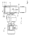
- edge-banding machine 1 in particular of the linear monolateral type, for edge-banding workpieces 2 to be machined, for example made of wood or similar materials.
- the edge-banding machine 1 may comprise a feeder 3, optionally of circular shape, arranged for supporting a laminar element in the form of a reel (which is not shown), to be applied to an edge of the workpiece 2.
- the edge-banding machine 1 may further comprise a frame 4, optionally supported by a plurality of foot elements 5, that rest on a floor of a room in which the machine 1 is located.
- the frame 4 can comprise a lower portion 6 that is contiguous with the foot elements 5, which is optionally hollow so as to define internally a cavity of substantially prismatic shape.
- this cavity which is optionally divided into several cavities that are adjacent to one another, can be housed, in particular, a large part of the electric cables that are necessary for the operation of the machine 1. Further, this cavity can receive a tank (which is not shown) containing an adhesive substance, typically glue, used for gluing the laminar element to the workpiece 2.
- the frame 4 may further comprise an upper portion 7, which is also optionally hollow so as to define, in the interior thereof, a further cavity of substantially prismatic shape.
- the upper portion 7 can receive a plurality of operating units 101, 102, 103, 104 (shown partially in Figure 2 and disclosed in greater detail below) arranged for performing subsequent machinings on the workpiece 2.
- the lower portion 6 and the upper portion 7 can be separated by an operating zone 8, in which the workpiece 2 is machined.
- the operating zone 8 is then substantially bound above by the upper portion 7 and below by the lower portion 6.
- the edge-banding machine 1 may comprise conveying means 9 for advancing the workpiece 2 along an advancement path P from an inlet zone 10 to an outlet zone 11 of the machine 1.
- the advancement path P which is optionally substantially parallel to an advancement direction X, the workpiece 2, as it advances, is subjected to subsequent machinings performed by the aforesaid plurality of operating units 101, 102, 103, 104 mounted on the machine 1.
- the conveying means 9 may comprise a conveyor belt 12 closed in a loop around a driving roller 13, around a first idle roller 14 and around a second idle roller 15, the latter being arranged in particular to maintain the conveyor belt 12 tensioned.
- the driving roller 13 can be driven by gearmotor means 24, shown in Figure 3 .
- the pressing means 41 comprising, for example, a plurality of rollers 42, exerts on the workpiece 2 a downward thrust in a substantially vertical direction.
- the conveyor belt 12 can be, for example, a conveyor belt of commercial type that is substantially similar to the conveyor belts used in the ceramic tile processing industry to advance tiles.
- the conveyor belt 12, a section of which is shown in greater detail in Figure 4 may comprise a plurality of layers, each of which is suitable for bestowing on the conveyor belt 12 particular mechanical and/or physical and/or chemical properties. It should be known that it is possible to define an operating portion 12a of the conveyor belt 12 like that portion of the conveyor belt 12 facing the operating zone 8.
- the conveyor belt 12 shown in Figure 4 may comprise a first external layer 16, for example made of an elastomer, configured for being brought into contact with the workpiece 2 to be machined.
- a lower surface 17 of the workpiece 2 rests on a contact surface 18 of the first layer 16.
- the conveyor belt 12 may further comprise a second layer 19, adjacent to the first layer 16 and, for example, made of a material comprising a double fabric that ensures the good tensioning and supporting features of the conveyor belt 12.
- the conveyor belt 12 may also comprise a third layer 20, adjacent to the second layer 19, and, for example, made of an elastomer, possibly having features that are different from the elastomer with which the first layer 16 can be made.
- the third layer 20 can be brought into contact laterally with a lateral containing element 30 that, as will be explained better below, limits side movement of the conveyor belt 12.
- the conveyor belt 12 is bounded by a contact surface 18, operationally brought into contact with the workpiece 2, and by a sliding surface 23, opposite the contact surface 18, and slidable on the resting plane 22.
- the contact surface 18 defines a conveying plane 25 on which the workpiece 2 is advanced along the advancement path P.
- the resting plane 22, extending substantially along the advancement direction X, comprises a coupling surface 26, in contact with, and on which, the sliding surface 23 of the fourth layer 21 of the conveyor belt 12 slides.
- the operating portion 12a of the conveyor belt 12 slides on the resting plane 22.
- the coupling surface 26 can be subjected to mechanical machinings that confer a good surface quality to the coupling surface 26.
- the resting plane 22 can be fixed to an elongated element 27, for example a hollow steel bar with a substantially square section shown in greater detail in Figure 3 .
- This elongated element 27 can extend prevalently along the advancement direction X optionally between the driving roller 13 and the first idle roller 14 and can support the resting plane 22.
- the elongated element 27 can be supported by a fixed bar connected to the frame 4. From the bar, substantially at a median zone of the bar, an arm extends that rotatably supports the second idle roller 15, which in turn comes into contact with the conveyor belt 12, tightening the conveyor belt 12. In particular the second idle roller 15, just like the first idle roller 14 and the driving roller 13, come into contact with the sliding surface 23 of the fourth layer 21 of the conveyor belt 12.
- the aforesaid lateral containing element 30 can be fixed to the elongated element 27, the aforesaid lateral containing element 30 being in particular made of plastics, such as, for example, polyethylene.
- the lateral containing element 30 can extend alongside the operating portion 12a of the conveyor belt 12 along the advancement direction X substantially for a length that is equal to that of the elongated element 27 and can be fixed to the latter by a plurality of fixing means 31, in particular threaded screws.
- the lateral containing element 30 can be brought into contact laterally, for example with the fourth layer 21 and with a portion of the thickness of the third layer 20 at a lateral contact surface 20a, as shown in Figure 4 .
- the lateral containing element 30 can be brought into contact laterally with an appropriate portion of the thickness of the conveyor belt 12 so as to lock the conveyor belt 12 and limit movements of the conveyor belt 12 along a direction Y, that is substantially transverse to the advancement direction X.
- the lateral containing element 30 is optionally arranged so as to be at a lower vertical height than the conveying plane 25 defined by the contact surface 18 on which the workpiece 2 rests.
- the edge-banding machine 1 may further comprise a supporting bar 32, extending optionally for a length substantially equal to the length of the machine 1 along the advancement direction X.
- the supporting bar 32 is movable along the direction Y to support the workpiece 2 to be machined in cooperation with the operating portion 12a of the conveyor belt 12.
- the supporting bar 32 is optionally movable by axially slidable coupling, for example of the type with a bar that is slidable within a cylindrical or prismatic guide.
- the coupling may comprise, optionally at opposite ends of the edge-banding machine 1, a guide 33 and a bar 34 that slides inside the guide 33 and is optionally fixed to connecting portions 35 of the supporting bar 32.
- the guides 33 optionally fixed to the lower portion 6 of the machine 1, guide the movement of the respective bars 34 along the direction Y.
- the supporting bar 32 comprises a plurality of rolling elements 36, in particular cylindrical rollers, on the side surfaces of which the workpiece 2 to be machined can slide. It should be noted that the contact points between these rolling elements 36 and the workpiece 2 are substantially comprised in the conveying plane 25.
- the edge-banding machine 1 may comprise an encoder 37 ( Figure 1 ) optionally mounted coaxially on a shaft of the first idle roller 14 to detect an angular position of this shaft and thus of the first idle roller 14.
- the encoder 37 can be supported by a plate 38 fixed to the elongated element 27 and to the aforesaid shaft, as shown in Figure 1 .
- the edge-banding machine 1 may further comprise a control and management unit 39 for controlling and commanding the plurality of operating units 101, 102, 103, 104 that operate on the workpiece 2 and the conveying means 9, in particular the advancement of the conveyor belt 12.
- the control and management unit 39 can be further arranged for receiving the electric signals sent by the encoder 37 that indicate the angular position of the first idle roller 14, and consequently the advancement of the conveyor belt 12. It should be noted that the encoder 37, mounted on the first idle roller 14, enables the position of the conveyor belt 12 to be detected, considering this position substantially coinciding with the angular position of the first idle roller 14.
- the machine 1 can be provided with an interface 40 by means of which an operator can insert the parameters of the workpiece 2 to be machined and of the machinings to be performed inside the control and management unit 39.
- the edge-banding machine 1 in particular of the linear monolateral type, enables a laminar element to be applied to an edge of a workpiece 2 to be machined, for example that is made of wood or similar materials, i.e. enables the workpiece 2 to be edge-banded.
- the operator positions the laminar element, which possibly is in form of a reel, on a feeder 3 of the edge-banding machine 1. It should be noted that this operation might not be necessary if the laminar element with which the workpiece 2 has to be edge-banded is the same as the one used to edge-band other workpieces that have just been machined.
- the operator adjusts, generally manually, the position of a supporting bar 32 along a direction Y in function of the size of the workpiece 2 to be machined in the direction Y, i.e. in function of the width of the workpiece 2.
- the operator positions the workpiece 2 at an inlet zone 10 of the edge-banding machine 1 by resting the workpiece on an operating portion 12a of a conveyor belt 12 and on the supporting bar 32.
- gearmotor means 24 drives the conveyor belt 12
- the workpiece 2 advances along an advancement path P that is substantially parallel to an advancement direction X.
- the workpiece 2 passes through an operating zone 8, in which the operating units 101, 102, 103, 104 comprised in the machine 1 perform successive machinings thereupon.
- the workpiece 2 is maintained pressed against the operating portion 12a of the conveyor belt 12 by pressing means 41, for example comprising a plurality of rollers 42.
- the operating units 101, 102, 103, 104 of the edge-banding machine 1 are generally that of known type mounted on known edge-banding machines.
- the aforesaid operating units 101, 102, 103, 104 comprise in succession along the advancement direction X: a gluing unit 101 for gluing the laminar element to an edge of the workpiece 2 to be machined, second pressing means 102 that is operationally arranged after the gluing unit 101 to press the laminar element against the edge of the workpiece 2 to be machined so as to fix to the workpiece 2 the laminar element.
- the operating units 101, 102, 103, 104 comprise at least one operating unit 103 to remove material protruding laterally and/or above and/or below said edge from the laminar element fixed to the edge.
- the operating units 101, 102, 103, 104 further comprise optionally, at least one finishing unit 104 for performing surface finishing machinings on the edge of the workpiece.
- the finishing unit 104 comprises a scraping unit for finishing the edge of the workpiece 2, and, optionally, brushes for cleaning and polishing the edge of the workpiece 2 to which the laminar element has been applied.
- the workpiece 2 exits the operating zone 8 at an outlet zone 11, from which the operator can remove the workpiece 2.
- a laminar element has been applied to an edge of the workpiece 2 and the tasks disclosed above have to be repeated for a number of times that is equal to the number of edges of the workpiece 2 that have to be edge-banded, thus generally another three times, so as to complete edge-banding of the workpiece 2.
- edge-banding machine 1 of the linear monolateral type in which the workpieces 2 to be machined are moved with regular motion by the conveyor belt 12 through the operating zone 8. Further, the edge-banding machine 1, in which the pressing means 41 maintains the workpiece 2 to be machined pressed against the conveyor belt 12, retains the workpiece 2 in a firm and effective manner.
- the conveyor belt 12 can be mounted and dismounted by the operator in a very short time.
- the edge-banding machine 1 thus enables workpieces 2 to be edge-banded in a precise and accurate manner without ruining the workpieces being machined, i.e. without damaging the final aesthetic appearance thereof.
- the encoder 37 can be mounted coaxially to a supporting shaft of the driving roller 13, or to a respective supporting shaft of the second idle roller 15, and thus not on the supporting shaft of the first idle roller 14.
Landscapes
- Life Sciences & Earth Sciences (AREA)
- Engineering & Computer Science (AREA)
- Mechanical Engineering (AREA)
- Wood Science & Technology (AREA)
- Forests & Forestry (AREA)
- Basic Packing Technique (AREA)
- Soil Working Implements (AREA)
- Confectionery (AREA)
- Bakery Products And Manufacturing Methods Therefor (AREA)
Applications Claiming Priority (1)
| Application Number | Priority Date | Filing Date | Title |
|---|---|---|---|
| IT000126A ITMO20090126A1 (it) | 2009-05-15 | 2009-05-15 | Macchina bordatrice |
Publications (1)
| Publication Number | Publication Date |
|---|---|
| EP2251165A1 true EP2251165A1 (de) | 2010-11-17 |
Family
ID=41435375
Family Applications (1)
| Application Number | Title | Priority Date | Filing Date |
|---|---|---|---|
| EP10162393A Withdrawn EP2251165A1 (de) | 2009-05-15 | 2010-05-10 | Kantenanleimmaschine |
Country Status (3)
| Country | Link |
|---|---|
| EP (1) | EP2251165A1 (de) |
| BR (1) | BRPI1001397A2 (de) |
| IT (1) | ITMO20090126A1 (de) |
Cited By (15)
| Publication number | Priority date | Publication date | Assignee | Title |
|---|---|---|---|---|
| CN102114662A (zh) * | 2010-12-07 | 2011-07-06 | 东莞市南兴木工机械有限公司 | 编码器控制的重型自动封边机 |
| ITMO20110130A1 (it) * | 2011-05-24 | 2012-11-25 | Scm Group Spa | Macchina bordatrice |
| CN103707385A (zh) * | 2013-12-12 | 2014-04-09 | 余成月 | 木板封边机 |
| CN103878862A (zh) * | 2014-03-03 | 2014-06-25 | 东莞市南兴家具装备制造股份有限公司 | 双端封边机的传动链条控制装置 |
| CN103878863A (zh) * | 2014-03-03 | 2014-06-25 | 东莞市南兴家具装备制造股份有限公司 | 大跨距双端封边机 |
| CN104354217A (zh) * | 2014-10-11 | 2015-02-18 | 东莞市南兴家具装备制造股份有限公司 | 封边机的封边带前后平切装置 |
| CN106042141A (zh) * | 2016-07-18 | 2016-10-26 | 青岛帝森露西娜厨具有限公司 | 全自动直角封边机 |
| CN106363766A (zh) * | 2016-11-15 | 2017-02-01 | 佛山市豪伟德机械有限公司 | 一种封边机的平刮边机构 |
| CN106426504A (zh) * | 2016-11-15 | 2017-02-22 | 佛山市豪伟德机械有限公司 | 一种分离安装的无动力修边机构 |
| CN112536882A (zh) * | 2020-12-04 | 2021-03-23 | 重庆非可智能家居有限公司 | 一种改进型门板生产用封边机 |
| EP3875176A2 (de) | 2020-03-04 | 2021-09-08 | Luigino Salvador | Leimverteileranordnung für eine kantenanleimmaschine und verfahren zum kantenanleimen von platten |
| WO2022226922A1 (zh) * | 2021-04-29 | 2022-11-03 | 南兴装备股份有限公司 | 一种高速双端封边机的控制系统 |
| CN115535519A (zh) * | 2022-09-21 | 2022-12-30 | 漳州市百事得家具有限公司 | 一种应用于定制家具生产的智能柔性封边生产线 |
| CN115972028A (zh) * | 2023-01-03 | 2023-04-18 | 北京大为家具集团有限公司 | 一种家具型材打磨装置 |
| IT202200002024A1 (it) | 2022-02-04 | 2023-08-04 | Ecosys S R L | Apparato per lavorazione e/o trattamento di una regione di bordo di un pezzo da lavorare |
Citations (3)
| Publication number | Priority date | Publication date | Assignee | Title |
|---|---|---|---|---|
| US2924007A (en) * | 1960-02-09 | Method for securing rubber-like weather stripping | ||
| DE1914358A1 (de) * | 1969-03-21 | 1970-10-01 | Paul Ott Kg Maschinenfabrik | Maschine zum Anleimen von Leisten,Baendern,insbesondere Kunststoff-Rollenmaterial u.dgl. |
| EP0897781A2 (de) * | 1997-08-22 | 1999-02-24 | E.I. Du Pont De Nemours And Company | Verfahren und Vorrichtung zur Kantenumleimung |
-
2009
- 2009-05-15 IT IT000126A patent/ITMO20090126A1/it unknown
-
2010
- 2010-05-10 EP EP10162393A patent/EP2251165A1/de not_active Withdrawn
- 2010-05-14 BR BRPI1001397 patent/BRPI1001397A2/pt not_active IP Right Cessation
Patent Citations (3)
| Publication number | Priority date | Publication date | Assignee | Title |
|---|---|---|---|---|
| US2924007A (en) * | 1960-02-09 | Method for securing rubber-like weather stripping | ||
| DE1914358A1 (de) * | 1969-03-21 | 1970-10-01 | Paul Ott Kg Maschinenfabrik | Maschine zum Anleimen von Leisten,Baendern,insbesondere Kunststoff-Rollenmaterial u.dgl. |
| EP0897781A2 (de) * | 1997-08-22 | 1999-02-24 | E.I. Du Pont De Nemours And Company | Verfahren und Vorrichtung zur Kantenumleimung |
Cited By (23)
| Publication number | Priority date | Publication date | Assignee | Title |
|---|---|---|---|---|
| CN102114662B (zh) * | 2010-12-07 | 2012-09-19 | 东莞市南兴家具装备制造股份有限公司 | 编码器控制的重型自动封边机 |
| CN102114662A (zh) * | 2010-12-07 | 2011-07-06 | 东莞市南兴木工机械有限公司 | 编码器控制的重型自动封边机 |
| ITMO20110130A1 (it) * | 2011-05-24 | 2012-11-25 | Scm Group Spa | Macchina bordatrice |
| EP2527108A1 (de) * | 2011-05-24 | 2012-11-28 | SCM Group S.p.A. | Kantenverkleidungsmaschine |
| CN103707385A (zh) * | 2013-12-12 | 2014-04-09 | 余成月 | 木板封边机 |
| CN103878863B (zh) * | 2014-03-03 | 2015-11-18 | 东莞市南兴家具装备制造股份有限公司 | 大跨距双端封边机 |
| CN103878862A (zh) * | 2014-03-03 | 2014-06-25 | 东莞市南兴家具装备制造股份有限公司 | 双端封边机的传动链条控制装置 |
| CN103878863A (zh) * | 2014-03-03 | 2014-06-25 | 东莞市南兴家具装备制造股份有限公司 | 大跨距双端封边机 |
| CN103878862B (zh) * | 2014-03-03 | 2015-11-18 | 东莞市南兴家具装备制造股份有限公司 | 双端封边机的传动链条控制装置 |
| CN104354217B (zh) * | 2014-10-11 | 2016-04-06 | 东莞市南兴家具装备制造股份有限公司 | 封边机的封边带前后平切装置 |
| CN104354217A (zh) * | 2014-10-11 | 2015-02-18 | 东莞市南兴家具装备制造股份有限公司 | 封边机的封边带前后平切装置 |
| CN106042141A (zh) * | 2016-07-18 | 2016-10-26 | 青岛帝森露西娜厨具有限公司 | 全自动直角封边机 |
| CN106363766A (zh) * | 2016-11-15 | 2017-02-01 | 佛山市豪伟德机械有限公司 | 一种封边机的平刮边机构 |
| CN106426504A (zh) * | 2016-11-15 | 2017-02-22 | 佛山市豪伟德机械有限公司 | 一种分离安装的无动力修边机构 |
| CN106426504B (zh) * | 2016-11-15 | 2018-12-21 | 佛山市豪伟德机械有限公司 | 一种分离安装的无动力修边机构 |
| EP3875176A2 (de) | 2020-03-04 | 2021-09-08 | Luigino Salvador | Leimverteileranordnung für eine kantenanleimmaschine und verfahren zum kantenanleimen von platten |
| EP3875175A1 (de) | 2020-03-04 | 2021-09-08 | Luigino Salvador | Leimverteileranordnung für kantenanleimmaschine und verfahren zum kantenanleimen von platten |
| CN112536882A (zh) * | 2020-12-04 | 2021-03-23 | 重庆非可智能家居有限公司 | 一种改进型门板生产用封边机 |
| WO2022226922A1 (zh) * | 2021-04-29 | 2022-11-03 | 南兴装备股份有限公司 | 一种高速双端封边机的控制系统 |
| IT202200002024A1 (it) | 2022-02-04 | 2023-08-04 | Ecosys S R L | Apparato per lavorazione e/o trattamento di una regione di bordo di un pezzo da lavorare |
| EP4223469A1 (de) | 2022-02-04 | 2023-08-09 | ECOSYS S.r.l. | Gerät zur bearbeitung und/oder behandlung eines kantenbereichs eines werkstücks |
| CN115535519A (zh) * | 2022-09-21 | 2022-12-30 | 漳州市百事得家具有限公司 | 一种应用于定制家具生产的智能柔性封边生产线 |
| CN115972028A (zh) * | 2023-01-03 | 2023-04-18 | 北京大为家具集团有限公司 | 一种家具型材打磨装置 |
Also Published As
| Publication number | Publication date |
|---|---|
| BRPI1001397A2 (pt) | 2011-12-20 |
| ITMO20090126A1 (it) | 2010-11-16 |
Similar Documents
| Publication | Publication Date | Title |
|---|---|---|
| EP2251165A1 (de) | Kantenanleimmaschine | |
| EP2181799A1 (de) | Automatische Bördelstation für Tafeln mit verschiedenen Peripherieprofilen | |
| CN110774090B (zh) | 一种木板边角打磨机 | |
| CN110328609B (zh) | 一种木材砂光机的自动上料机构 | |
| CA2199982C (en) | Belt refurbishing method and apparatus | |
| CN104384616B (zh) | 一种切断机械 | |
| US6748995B2 (en) | Apparatus and method for manufacturing panels from wood pieces | |
| CN112775852A (zh) | 具有多个驱动单元的线集中型水刀切割装置 | |
| US20110003539A1 (en) | Apparatus for double-sided grinding | |
| WO2013013809A1 (en) | Method for producing flexible end grain balsa panels | |
| KR101744675B1 (ko) | 쪽대의 절곡부 브이 커팅장치 | |
| EP2527108A1 (de) | Kantenverkleidungsmaschine | |
| CN220561126U (zh) | 一种机械加工用板材定位修边装置 | |
| DE19917741A1 (de) | Vorrichtung zum Anfahren eines Kantenstreifens an eine Schmalflächenseite einer eckigen Platte | |
| KR101521582B1 (ko) | 목재패널의 모서리 처리장치 | |
| KR101791970B1 (ko) | 판재 엣지 가공에서의 이송 판재 누름장치 | |
| CN2803622Y (zh) | 砂光研磨设备结构 | |
| PL202351B1 (pl) | Linia technologiczna do maszynowej obróbki płytowych detali z drewna i/lub substytutów drewna | |
| CN107097073A (zh) | 自动送料转向的数控开槽机 | |
| CN207682468U (zh) | 一种皮带分条机 | |
| US8066039B2 (en) | Rail end former for cabinet doors | |
| CN219337960U (zh) | 一种修条机 | |
| CN214557869U (zh) | 自动切割机 | |
| JPH06102321B2 (ja) | 木材又は類似材料、たとえばプラスチックから成る末加工物を切削加工する方法 | |
| CN210255472U (zh) | 一种数控节能液压切边、整形机 |
Legal Events
| Date | Code | Title | Description |
|---|---|---|---|
| PUAI | Public reference made under article 153(3) epc to a published international application that has entered the european phase |
Free format text: ORIGINAL CODE: 0009012 |
|
| AK | Designated contracting states |
Kind code of ref document: A1 Designated state(s): AL AT BE BG CH CY CZ DE DK EE ES FI FR GB GR HR HU IE IS IT LI LT LU LV MC MK MT NL NO PL PT RO SE SI SK SM TR |
|
| AX | Request for extension of the european patent |
Extension state: BA ME RS |
|
| STAA | Information on the status of an ep patent application or granted ep patent |
Free format text: STATUS: THE APPLICATION IS DEEMED TO BE WITHDRAWN |
|
| 18D | Application deemed to be withdrawn |
Effective date: 20110518 |