EP2251490B1 - Dispositif et procédé d'introduction de tuyaux dans le sol - Google Patents
Dispositif et procédé d'introduction de tuyaux dans le sol Download PDFInfo
- Publication number
- EP2251490B1 EP2251490B1 EP09006634A EP09006634A EP2251490B1 EP 2251490 B1 EP2251490 B1 EP 2251490B1 EP 09006634 A EP09006634 A EP 09006634A EP 09006634 A EP09006634 A EP 09006634A EP 2251490 B1 EP2251490 B1 EP 2251490B1
- Authority
- EP
- European Patent Office
- Prior art keywords
- pipe
- vibration generators
- tube
- vibration
- degrees
- Prior art date
- Legal status (The legal status is an assumption and is not a legal conclusion. Google has not performed a legal analysis and makes no representation as to the accuracy of the status listed.)
- Not-in-force
Links
- 238000000034 method Methods 0.000 title claims abstract description 30
- 239000002689 soil Substances 0.000 title claims abstract description 20
- 230000010355 oscillation Effects 0.000 claims abstract description 11
- 239000000463 material Substances 0.000 claims description 8
- 238000003780 insertion Methods 0.000 claims description 3
- 230000037431 insertion Effects 0.000 claims description 3
- 238000005265 energy consumption Methods 0.000 description 4
- 244000089486 Phragmites australis subsp australis Species 0.000 description 3
- 238000011161 development Methods 0.000 description 3
- 230000018109 developmental process Effects 0.000 description 3
- 230000003068 static effect Effects 0.000 description 3
- 238000000418 atomic force spectrum Methods 0.000 description 2
- 239000004576 sand Substances 0.000 description 2
- 230000000694 effects Effects 0.000 description 1
- 238000004519 manufacturing process Methods 0.000 description 1
- 239000002184 metal Substances 0.000 description 1
Images

Classifications
-
- E—FIXED CONSTRUCTIONS
- E02—HYDRAULIC ENGINEERING; FOUNDATIONS; SOIL SHIFTING
- E02D—FOUNDATIONS; EXCAVATIONS; EMBANKMENTS; UNDERGROUND OR UNDERWATER STRUCTURES
- E02D7/00—Methods or apparatus for placing sheet pile bulkheads, piles, mouldpipes, or other moulds
- E02D7/18—Placing by vibrating
-
- E—FIXED CONSTRUCTIONS
- E02—HYDRAULIC ENGINEERING; FOUNDATIONS; SOIL SHIFTING
- E02D—FOUNDATIONS; EXCAVATIONS; EMBANKMENTS; UNDERGROUND OR UNDERWATER STRUCTURES
- E02D5/00—Bulkheads, piles, or other structural elements specially adapted to foundation engineering
- E02D5/22—Piles
- E02D5/34—Concrete or concrete-like piles cast in position ; Apparatus for making same
- E02D5/38—Concrete or concrete-like piles cast in position ; Apparatus for making same making by use of mould-pipes or other moulds
Definitions
- the invention relates to a method for introducing pipes in the ground according to the preamble of claim 1.
- the invention further relates to a device for carrying out the aforementioned method according to the preamble of claim 11 and a pipe for introduction into the ground by means of the aforementioned method according to the Claim 15.
- vibration generators For introducing the pipes into the ground usually vibration generator are used.
- the vibration generators are linearly acting vibration exciters whose flying power is generated by rotating balancing.
- the size of the unbalance is also called the static moment.
- the history The speed of the linear vibration exciter corresponds to a periodically recurring function, in particular a sine function.
- the waves on which the imbalances rotate are arranged parallel to one another and move in opposite directions, which causes horizontally occurring centrifugal forces to cancel each other out and thus the centrifugal forces generated effectively only rest in the vertical direction.
- the invention aims to remedy this situation.
- the invention has for its object to provide a method for introducing pipes into the ground, in which the energy consumption and the soil vibration during piling are reduced. According to the invention, this object is achieved by the features of the characterizing part of patent claim 1.
- a method for introducing pipes into the ground in which the energy consumption and the soil vibration during the piling process are reduced. Due to the simultaneous rotation of the tube, a reduction of the skin friction is achieved, as this significantly reduces the static friction between pile and soil. Adherence of the surrounding soil to the pipe is counteracted. As a result of the continuous sliding friction between pile and soil at the same time a reduction of soil vibration during piling is achieved. In addition, a "cutting" of the Pipe diameter causes in the soil, because the lower edge of the tube is not pushed frontally against the ground, but it moves oscillating.
- the helical oscillation of the tube is formed such that a movement of the tube as an ellipse on the tube wall is apparent, whose vertical radius is between 2 mm and 10 mm, preferably between 5 mm and 8 mm.
- the tube is provided with at least two circumferentially acting vibration generators whose centrifugal force is not linear, but is circumferential, wherein the unbalance receiving waves of the vibrator are aligned with the center of the circular cross section of the tube.
- the imbalance masses mounted on parallel shafts do not rotate in opposite directions.
- the force curve corresponds to a vector which acts radially with respect to the shaft axis and rotates with the unbalanced mass.
- the waves of the vibration generator are rotated in the same direction in rotation.
- an addition of the horizontally directed centrifugal forces is effected.
- vibration generators each offset by 120 degrees to each other on the pipe.
- the vibration generator are designed to be single-wave.
- the linearly acting vibration generator are employed at an angle of 15 and 75 degrees to the cross-sectional plane of the tube.
- the vibration generators are advantageously designed such that the effective centrifugal force acts in the direction of the angle of attack of the vibration generator. Due to the oblique employment of the vibration generator to the edge of the tube, as it is a fferengangsoszillation the tube can be achieved.
- a helix for conveying soil material from the tube is arranged on the inner wall of the tube.
- the helix is stepped, preferably as a corrugated sheet. educated. As a result, a high Reibuge bronze can be achieved, which is feasible with single-wave vibrators.
- the invention is further based on the object to provide a device for carrying out the aforementioned method, which allows a reduction in energy consumption during piling. According to the invention, this object is solved by the features of the characterizing part of patent claim 11.
- an apparatus for carrying out the aforementioned method for introducing pipes is created in the ground, in which a reduction in energy consumption during piling is possible.
- the arrangement of the vibration generator on a plate allows a simple positionally accurate arrangement of the vibration generator on the edge of the pipe to be introduced into the soil.
- a plate may also be provided a frame or other linkage on which the vibration generator are arranged.
- the plate has means for receiving a tube, which are designed such that the inclusion of tubes of different outer and inner diameter is made possible.
- the use of the device is possible with different pipe designs.
- a device for attachment to a broker is arranged on the plate.
- the arrangement of the plate is made possible to a broker, whereby the vertical propulsion of the tube can be supported.
- At least two linearly acting vibration generator are arranged at an angle of between 15 and 75 degrees to the plate plane.
- the invention further provides a tube for introduction into the soil via the aforementioned method with the features of claim 15.
- a tube for introduction into the soil via the aforementioned method with the features of claim 15.
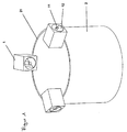
- a tube 2 is provided with three oscillators 1, which are designed as a single-wave exciter cells and each offset by 120 degrees to each other on the tube.
- the imbalance masses 12 receiving waves 11 of the vibrator 1 are respectively directed to the center of the circular cross-section 21 of the tube 2.
- the shafts 11 of the vibrators 1 are rotated in the same direction, whereby the centrifugal forces of the vibrators are added in both the vertical and in the horizontal direction.
- the horizontal centrifugal forces act tangentially to the tube 2, whereby this is set in rotation; the vertical centrifugal forces cause a vertical, sinusoidal oscillation, which, in combination with the weight force of the vibrator acting in the advancing direction, causes a feed movement into the ground.
- the superimposition of the horizontal and vertical movement results in a helical oscillation of the tube in the direction of the ground. In this vibration process, the movement of the tube against a fixed point as an ellipse on the pipe wall is characterized.
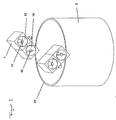
- FIG. 2 In the embodiment according to FIG. 2 are two twin-shaft vibrator 1 at an angle of 35 degrees to the pipe cross-sectional plane 21 employed.
- the vibration generators 1 each have two shafts 11, 13 provided with imbalance masses 12, 14, which are rotated in opposite directions to one another.
- the resulting centrifugal force acts in the direction of the angle of attack of 35 degrees to the tube cross-sectional plane 21.
- this drive form of the tube ground mass, in particular loose sand can be conveyed upwards during the introduction process in the tube via a helix arranged on the tube inner wall. A boring or sucking out of the tube can be omitted in this case.
- FIG. 3 the schematic arrangement for carrying out the method according to the invention is shown.
- a plate 3 is fixed, on the opposite two single-wave vibrator 1 are arranged.
- the waves 11 of the vibration generator 1 are directed in the direction of the center of the plate 3.
- a guide 31 is introduced, through which a guide rod 4 is guided.
- a guide insert 22 is further introduced within the tube 2.
- waves 11 of the vibrator 1 are rotated in the same direction, whereby a helical oscillation of the tube 2 is effected.
- the tube 2 is drilled along the guide rod 4 in the bottom 5.
- the plate 3 with the vibrators 1 and the guide rod 4 is removed from the tube. Subsequently, the material within the tube 2 is discharged and the interior of the tube 2 is filled with concrete. Subsequently, the tube 2 can be pulled out of the ground before the concrete has hardened.
Landscapes
- Engineering & Computer Science (AREA)
- Structural Engineering (AREA)
- Life Sciences & Earth Sciences (AREA)
- General Life Sciences & Earth Sciences (AREA)
- Mining & Mineral Resources (AREA)
- Paleontology (AREA)
- Civil Engineering (AREA)
- General Engineering & Computer Science (AREA)
- Investigation Of Foundation Soil And Reinforcement Of Foundation Soil By Compacting Or Drainage (AREA)
Claims (15)
- Procédé destiné à introduire un tuyau dans le sol, sachant que le tuyau entre en oscillation sous l'action d'au moins un générateur d'oscillations, caractérisé en ce que les oscillations d'au moins un générateur d'oscillations (1) sont transmises au tuyau (2) de telle sorte que le tuyau (2) entre en rotation en plus du mouvement linéaire, ce qui a pour effet d'imprimer au tuyau (2) une oscillation en forme de filet de vis hélicoïdal.
- Procédé selon la revendication 1, caractérisé en ce que l'oscillation du tuyau (2) en forme de filet de vis hélicoïdal est configurée de telle sorte qu'un mouvement du tuyau (2) se dessine sous forme d'ellipse sur la paroi du tuyau, ellipse dont le rayon vertical est compris entre 2 mm et 10 mm, de préférence entre 5 mm et 8 mm.
- Procédé selon la revendication 1 ou 2, caractérisé en ce que le tuyau est équipé d'au moins deux générateurs d'oscillations, sachant que les arbres (11, 13) du générateur (1) qui reçoivent les masselottes (12, 14) sont orientés vers le centre de la section circulaire (21) du tuyau (2).
- Procédé selon la revendication 3, caractérisé en ce que les arbres (11, 13) des générateurs d'oscillations (1) agissant circonférentiellement sont mis en rotation réciproquement dans le même sens.
- Procédé selon la revendication 4, caractérisé en ce que le générateur d'oscillations est configuré de sorte à générer une force centrifuge agissant circonférentiellement.
- Procédé selon les revendications 3 à 5, caractérisé en ce que les générateurs d'oscillations (1) sont réalisés mono-arbre.
- Procédé selon l'une des revendications 3 à 6, caractérisé en ce qu'au moins trois générateurs d'oscillations (1) sont agencés symétriquement répartis sur la circonférence du tube (2).
- Procédé selon la revendication 3, caractérisé en ce qu'au moins deux générateurs d'oscillations (1) agissant linéairement sont disposés selon un angle compris entre 15 et 75 degrés sur le plan de la section du tube.
- Procédé selon l'une des revendications précédentes, caractérisé en ce que contre la paroi intérieure du tuyau (2) est agencée une spirale servant à évacuer la terre hors du tuyau (2).
- Procédé selon la revendication 9, caractérisé en ce que la spirale est configurée en escaliers, de préférence sous forme de tôle ondulée.
- Dispositif pour exécuter un procédé selon l'une des revendications précédentes, comprenant une plaque (3) sur laquelle sont agencés au moins deux générateurs d'oscillations (1), générateurs dont les arbres (11, 13) recevant les masselottes (12, 14) sont orientés vers le centre de la plaque, laquelle se laisse fixer sur un tuyau.
- Dispositif selon la revendication 11, caractérisé en ce que la plaque (3) présente des moyens permettant de recevoir un tuyau (2), lesdits moyens étant configurés de sorte à permettre la réception de tuyaux présentant des diamètres extérieurs et intérieurs différents.
- Dispositif selon la revendication 11 ou 12, caractérisé en ce que trois générateurs d'oscillations (1) sont disposés espacés chacun de 120 degrés sur le tuyau (2).
- Dispositif selon la revendication 11 ou 12, caractérisé en ce qu'au moins deux générateurs d'oscillations (1) sont agencés pour former, par rapport au plan de la section du tuyau, un angle compris entre 15 et 75 degrés, de préférence entre 30 et 60 degrés.
- Dispositif selon l'une des revendications précédentes 11 à 14, caractérisé en ce que ledit dispositif contient un tuyau à introduire dans le sol au moyen d'un procédé selon la revendication 1, tuyau sur la paroi intérieure duquel se trouve une spirale destinée à évacuer la terre hors du tuyau (2) pendant le processus d'introduction.
Priority Applications (2)
| Application Number | Priority Date | Filing Date | Title |
|---|---|---|---|
| EP09006634A EP2251490B1 (fr) | 2009-05-16 | 2009-05-16 | Dispositif et procédé d'introduction de tuyaux dans le sol |
| AT09006634T ATE550494T1 (de) | 2009-05-16 | 2009-05-16 | Vorrichtung und verfahren zum einbringen von rohren in den boden |
Applications Claiming Priority (1)
| Application Number | Priority Date | Filing Date | Title |
|---|---|---|---|
| EP09006634A EP2251490B1 (fr) | 2009-05-16 | 2009-05-16 | Dispositif et procédé d'introduction de tuyaux dans le sol |
Publications (2)
| Publication Number | Publication Date |
|---|---|
| EP2251490A1 EP2251490A1 (fr) | 2010-11-17 |
| EP2251490B1 true EP2251490B1 (fr) | 2012-03-21 |
Family
ID=40848745
Family Applications (1)
| Application Number | Title | Priority Date | Filing Date |
|---|---|---|---|
| EP09006634A Not-in-force EP2251490B1 (fr) | 2009-05-16 | 2009-05-16 | Dispositif et procédé d'introduction de tuyaux dans le sol |
Country Status (2)
| Country | Link |
|---|---|
| EP (1) | EP2251490B1 (fr) |
| AT (1) | ATE550494T1 (fr) |
Family Cites Families (4)
| Publication number | Priority date | Publication date | Assignee | Title |
|---|---|---|---|---|
| EP0225420B1 (fr) * | 1985-12-13 | 1990-03-07 | Franz Plasser Bahnbaumaschinen-Industriegesellschaft m.b.H. | Installation pour enfoncer des tuyaux de fondation ou similaires dans des couches de sol par un dispositif de vibration |
| DE10029984A1 (de) * | 2000-06-26 | 2002-02-21 | Fritz Gehbauer | Verfahren zur Regelung des Betriebs einer Vibrationsramme |
| US6672805B1 (en) * | 2001-09-27 | 2004-01-06 | American Piledriving Equipment, Inc. | Systems and methods for driving large diameter caissons |
| DE102007049435A1 (de) * | 2007-10-16 | 2009-04-30 | Thyssenkrupp Gft Tiefbautechnik Gmbh | Vorrichtung zur Erzeugung von Schwingungen |
-
2009
- 2009-05-16 EP EP09006634A patent/EP2251490B1/fr not_active Not-in-force
- 2009-05-16 AT AT09006634T patent/ATE550494T1/de active
Also Published As
| Publication number | Publication date |
|---|---|
| ATE550494T1 (de) | 2012-04-15 |
| EP2251490A1 (fr) | 2010-11-17 |
Similar Documents
| Publication | Publication Date | Title |
|---|---|---|
| EP2105214B1 (fr) | Dispositif de production de vibrations | |
| EP3951057B1 (fr) | Système de rouleau de traitement du sol pour une machine de traitement du sol | |
| DE1634267A1 (de) | Verfahren und Vorrichtung zum Eintreiben langgestreckter Koerper in koerniges Medium in deren Laengsrichtung | |
| EP2732100B1 (fr) | Excitateur à balourd pour compacteur de sol | |
| EP2392413B1 (fr) | Marteaux à vibration | |
| EP3450631B1 (fr) | Vibreur en profondeur avec une masse non équilibrée réglable | |
| EP2105213A1 (fr) | Dispositif de production de vibrations | |
| EP2251490B1 (fr) | Dispositif et procédé d'introduction de tuyaux dans le sol | |
| EP3243573B1 (fr) | Dispositif de production de vibrations | |
| EP3215678B1 (fr) | Vibrofonceur | |
| EP2242590B1 (fr) | Excitateur à balourds comprenant un ou plusieurs balourds rotatifs | |
| DE102014019139A1 (de) | Tiefenrüttler mit veränderbarer Unwucht | |
| DE2802648C2 (de) | In der Marschrichtung umsteuerbare Rüttelplatte | |
| DE934220C (de) | Verfahren und Vorrichtung zum Eintreiben oder Ziehen von Pfaehlen, Bohlen, Rohren u. dgl. | |
| EP3165290B1 (fr) | Dispositif de production de vibrations et procede d'introduction de profile dans un sol | |
| DE102011008576A1 (de) | Verfahren und Vorrichtung zur Erzeugung einer schwingenden Bewegung einer Masse | |
| DE102014225726A1 (de) | Verfahren und Vorrichtungen zur Baugrundverbesserung | |
| EP0589196A1 (fr) | Dispositif pour la fabrication de tuyaux en béton | |
| EP3384096B1 (fr) | Agencement pour produire une force de compression pulsée | |
| DE858532C (de) | Verfahren zum Loesen fest gewordener Rohre in Tiefbohrungen durch Schwingungen | |
| DE102004035128A1 (de) | Prüfvorrichtung und Verfahren zum Prüfen von Fahrzeug-Stabilisatoren | |
| EP3051028B1 (fr) | Procede de battage par vibration | |
| DE4413471C1 (de) | Verfahren zur Herstellung von liegenden und/oder geneigten, verfestigten Säulen im Baugrund sowie Vorrichtung zur Durchführung des Verfahrens nebst Anwendung | |
| DE2521015B2 (de) | Vorrichtung zur Erzeugung von akustischen Schwingungen in einem flüssigen Medium | |
| EP3051027B1 (fr) | Procede de mise en place par vibrations et systeme de placer par vibrations |
Legal Events
| Date | Code | Title | Description |
|---|---|---|---|
| PUAI | Public reference made under article 153(3) epc to a published international application that has entered the european phase |
Free format text: ORIGINAL CODE: 0009012 |
|
| 17P | Request for examination filed |
Effective date: 20091021 |
|
| AK | Designated contracting states |
Kind code of ref document: A1 Designated state(s): AT BE BG CH CY CZ DE DK EE ES FI FR GB GR HR HU IE IS IT LI LT LU LV MC MK MT NL NO PL PT RO SE SI SK TR |
|
| AX | Request for extension of the european patent |
Extension state: AL BA RS |
|
| GRAP | Despatch of communication of intention to grant a patent |
Free format text: ORIGINAL CODE: EPIDOSNIGR1 |
|
| GRAS | Grant fee paid |
Free format text: ORIGINAL CODE: EPIDOSNIGR3 |
|
| GRAA | (expected) grant |
Free format text: ORIGINAL CODE: 0009210 |
|
| AK | Designated contracting states |
Kind code of ref document: B1 Designated state(s): AT BE BG CH CY CZ DE DK EE ES FI FR GB GR HR HU IE IS IT LI LT LU LV MC MK MT NL NO PL PT RO SE SI SK TR |
|
| REG | Reference to a national code |
Ref country code: GB Ref legal event code: FG4D Free format text: NOT ENGLISH |
|
| REG | Reference to a national code |
Ref country code: CH Ref legal event code: EP |
|
| REG | Reference to a national code |
Ref country code: IE Ref legal event code: FG4D Free format text: LANGUAGE OF EP DOCUMENT: GERMAN |
|
| REG | Reference to a national code |
Ref country code: AT Ref legal event code: REF Ref document number: 550494 Country of ref document: AT Kind code of ref document: T Effective date: 20120415 |
|
| REG | Reference to a national code |
Ref country code: DE Ref legal event code: R096 Ref document number: 502009003052 Country of ref document: DE Effective date: 20120516 |
|
| REG | Reference to a national code |
Ref country code: NL Ref legal event code: T3 |
|
| PG25 | Lapsed in a contracting state [announced via postgrant information from national office to epo] |
Ref country code: LT Free format text: LAPSE BECAUSE OF FAILURE TO SUBMIT A TRANSLATION OF THE DESCRIPTION OR TO PAY THE FEE WITHIN THE PRESCRIBED TIME-LIMIT Effective date: 20120321 Ref country code: HR Free format text: LAPSE BECAUSE OF FAILURE TO SUBMIT A TRANSLATION OF THE DESCRIPTION OR TO PAY THE FEE WITHIN THE PRESCRIBED TIME-LIMIT Effective date: 20120321 Ref country code: NO Free format text: LAPSE BECAUSE OF FAILURE TO SUBMIT A TRANSLATION OF THE DESCRIPTION OR TO PAY THE FEE WITHIN THE PRESCRIBED TIME-LIMIT Effective date: 20120621 |
|
| LTIE | Lt: invalidation of european patent or patent extension |
Effective date: 20120321 |
|
| PG25 | Lapsed in a contracting state [announced via postgrant information from national office to epo] |
Ref country code: LV Free format text: LAPSE BECAUSE OF FAILURE TO SUBMIT A TRANSLATION OF THE DESCRIPTION OR TO PAY THE FEE WITHIN THE PRESCRIBED TIME-LIMIT Effective date: 20120321 Ref country code: GR Free format text: LAPSE BECAUSE OF FAILURE TO SUBMIT A TRANSLATION OF THE DESCRIPTION OR TO PAY THE FEE WITHIN THE PRESCRIBED TIME-LIMIT Effective date: 20120622 Ref country code: FI Free format text: LAPSE BECAUSE OF FAILURE TO SUBMIT A TRANSLATION OF THE DESCRIPTION OR TO PAY THE FEE WITHIN THE PRESCRIBED TIME-LIMIT Effective date: 20120321 |
|
| PG25 | Lapsed in a contracting state [announced via postgrant information from national office to epo] |
Ref country code: CY Free format text: LAPSE BECAUSE OF FAILURE TO SUBMIT A TRANSLATION OF THE DESCRIPTION OR TO PAY THE FEE WITHIN THE PRESCRIBED TIME-LIMIT Effective date: 20120321 |
|
| PG25 | Lapsed in a contracting state [announced via postgrant information from national office to epo] |
Ref country code: EE Free format text: LAPSE BECAUSE OF FAILURE TO SUBMIT A TRANSLATION OF THE DESCRIPTION OR TO PAY THE FEE WITHIN THE PRESCRIBED TIME-LIMIT Effective date: 20120321 Ref country code: SE Free format text: LAPSE BECAUSE OF FAILURE TO SUBMIT A TRANSLATION OF THE DESCRIPTION OR TO PAY THE FEE WITHIN THE PRESCRIBED TIME-LIMIT Effective date: 20120321 Ref country code: PL Free format text: LAPSE BECAUSE OF FAILURE TO SUBMIT A TRANSLATION OF THE DESCRIPTION OR TO PAY THE FEE WITHIN THE PRESCRIBED TIME-LIMIT Effective date: 20120321 Ref country code: CZ Free format text: LAPSE BECAUSE OF FAILURE TO SUBMIT A TRANSLATION OF THE DESCRIPTION OR TO PAY THE FEE WITHIN THE PRESCRIBED TIME-LIMIT Effective date: 20120321 Ref country code: RO Free format text: LAPSE BECAUSE OF FAILURE TO SUBMIT A TRANSLATION OF THE DESCRIPTION OR TO PAY THE FEE WITHIN THE PRESCRIBED TIME-LIMIT Effective date: 20120321 Ref country code: IS Free format text: LAPSE BECAUSE OF FAILURE TO SUBMIT A TRANSLATION OF THE DESCRIPTION OR TO PAY THE FEE WITHIN THE PRESCRIBED TIME-LIMIT Effective date: 20120721 Ref country code: SI Free format text: LAPSE BECAUSE OF FAILURE TO SUBMIT A TRANSLATION OF THE DESCRIPTION OR TO PAY THE FEE WITHIN THE PRESCRIBED TIME-LIMIT Effective date: 20120321 |
|
| BERE | Be: lapsed |
Owner name: ABI ANLAGENTECHNIK-BAUMASCHINEN-INDUSTRIEBEDARF M Effective date: 20120531 |
|
| PG25 | Lapsed in a contracting state [announced via postgrant information from national office to epo] |
Ref country code: PT Free format text: LAPSE BECAUSE OF FAILURE TO SUBMIT A TRANSLATION OF THE DESCRIPTION OR TO PAY THE FEE WITHIN THE PRESCRIBED TIME-LIMIT Effective date: 20120723 Ref country code: SK Free format text: LAPSE BECAUSE OF FAILURE TO SUBMIT A TRANSLATION OF THE DESCRIPTION OR TO PAY THE FEE WITHIN THE PRESCRIBED TIME-LIMIT Effective date: 20120321 |
|
| PG25 | Lapsed in a contracting state [announced via postgrant information from national office to epo] |
Ref country code: MC Free format text: LAPSE BECAUSE OF NON-PAYMENT OF DUE FEES Effective date: 20120531 |
|
| PLBE | No opposition filed within time limit |
Free format text: ORIGINAL CODE: 0009261 |
|
| STAA | Information on the status of an ep patent application or granted ep patent |
Free format text: STATUS: NO OPPOSITION FILED WITHIN TIME LIMIT |
|
| PG25 | Lapsed in a contracting state [announced via postgrant information from national office to epo] |
Ref country code: DK Free format text: LAPSE BECAUSE OF FAILURE TO SUBMIT A TRANSLATION OF THE DESCRIPTION OR TO PAY THE FEE WITHIN THE PRESCRIBED TIME-LIMIT Effective date: 20120321 |
|
| 26N | No opposition filed |
Effective date: 20130102 |
|
| REG | Reference to a national code |
Ref country code: IE Ref legal event code: MM4A |
|
| PG25 | Lapsed in a contracting state [announced via postgrant information from national office to epo] |
Ref country code: MK Free format text: LAPSE BECAUSE OF FAILURE TO SUBMIT A TRANSLATION OF THE DESCRIPTION OR TO PAY THE FEE WITHIN THE PRESCRIBED TIME-LIMIT Effective date: 20120321 Ref country code: IT Free format text: LAPSE BECAUSE OF FAILURE TO SUBMIT A TRANSLATION OF THE DESCRIPTION OR TO PAY THE FEE WITHIN THE PRESCRIBED TIME-LIMIT Effective date: 20120321 Ref country code: BE Free format text: LAPSE BECAUSE OF NON-PAYMENT OF DUE FEES Effective date: 20120531 |
|
| REG | Reference to a national code |
Ref country code: DE Ref legal event code: R097 Ref document number: 502009003052 Country of ref document: DE Effective date: 20130102 |
|
| PG25 | Lapsed in a contracting state [announced via postgrant information from national office to epo] |
Ref country code: IE Free format text: LAPSE BECAUSE OF NON-PAYMENT OF DUE FEES Effective date: 20120516 Ref country code: ES Free format text: LAPSE BECAUSE OF FAILURE TO SUBMIT A TRANSLATION OF THE DESCRIPTION OR TO PAY THE FEE WITHIN THE PRESCRIBED TIME-LIMIT Effective date: 20120702 |
|
| PG25 | Lapsed in a contracting state [announced via postgrant information from national office to epo] |
Ref country code: BG Free format text: LAPSE BECAUSE OF FAILURE TO SUBMIT A TRANSLATION OF THE DESCRIPTION OR TO PAY THE FEE WITHIN THE PRESCRIBED TIME-LIMIT Effective date: 20120621 Ref country code: MT Free format text: LAPSE BECAUSE OF FAILURE TO SUBMIT A TRANSLATION OF THE DESCRIPTION OR TO PAY THE FEE WITHIN THE PRESCRIBED TIME-LIMIT Effective date: 20120321 |
|
| REG | Reference to a national code |
Ref country code: CH Ref legal event code: PL |
|
| GBPC | Gb: european patent ceased through non-payment of renewal fee |
Effective date: 20130516 |
|
| PG25 | Lapsed in a contracting state [announced via postgrant information from national office to epo] |
Ref country code: LI Free format text: LAPSE BECAUSE OF NON-PAYMENT OF DUE FEES Effective date: 20130531 Ref country code: CH Free format text: LAPSE BECAUSE OF NON-PAYMENT OF DUE FEES Effective date: 20130531 |
|
| PG25 | Lapsed in a contracting state [announced via postgrant information from national office to epo] |
Ref country code: TR Free format text: LAPSE BECAUSE OF FAILURE TO SUBMIT A TRANSLATION OF THE DESCRIPTION OR TO PAY THE FEE WITHIN THE PRESCRIBED TIME-LIMIT Effective date: 20120321 Ref country code: GB Free format text: LAPSE BECAUSE OF NON-PAYMENT OF DUE FEES Effective date: 20130516 |
|
| PG25 | Lapsed in a contracting state [announced via postgrant information from national office to epo] |
Ref country code: LU Free format text: LAPSE BECAUSE OF NON-PAYMENT OF DUE FEES Effective date: 20120516 |
|
| PG25 | Lapsed in a contracting state [announced via postgrant information from national office to epo] |
Ref country code: HU Free format text: LAPSE BECAUSE OF FAILURE TO SUBMIT A TRANSLATION OF THE DESCRIPTION OR TO PAY THE FEE WITHIN THE PRESCRIBED TIME-LIMIT Effective date: 20090516 |
|
| PGFP | Annual fee paid to national office [announced via postgrant information from national office to epo] |
Ref country code: FR Payment date: 20140516 Year of fee payment: 6 Ref country code: DE Payment date: 20140508 Year of fee payment: 6 Ref country code: NL Payment date: 20140520 Year of fee payment: 6 |
|
| REG | Reference to a national code |
Ref country code: AT Ref legal event code: MM01 Ref document number: 550494 Country of ref document: AT Kind code of ref document: T Effective date: 20140516 |
|
| PG25 | Lapsed in a contracting state [announced via postgrant information from national office to epo] |
Ref country code: AT Free format text: LAPSE BECAUSE OF NON-PAYMENT OF DUE FEES Effective date: 20140516 |
|
| REG | Reference to a national code |
Ref country code: DE Ref legal event code: R119 Ref document number: 502009003052 Country of ref document: DE |
|
| REG | Reference to a national code |
Ref country code: NL Ref legal event code: MM Effective date: 20150601 |
|
| REG | Reference to a national code |
Ref country code: FR Ref legal event code: ST Effective date: 20160129 |
|
| PG25 | Lapsed in a contracting state [announced via postgrant information from national office to epo] |
Ref country code: DE Free format text: LAPSE BECAUSE OF NON-PAYMENT OF DUE FEES Effective date: 20151201 Ref country code: NL Free format text: LAPSE BECAUSE OF NON-PAYMENT OF DUE FEES Effective date: 20150601 |
|
| PG25 | Lapsed in a contracting state [announced via postgrant information from national office to epo] |
Ref country code: FR Free format text: LAPSE BECAUSE OF NON-PAYMENT OF DUE FEES Effective date: 20150601 |