EP2254632B1 - Inhalator - Google Patents
Inhalator Download PDFInfo
- Publication number
- EP2254632B1 EP2254632B1 EP09703440.9A EP09703440A EP2254632B1 EP 2254632 B1 EP2254632 B1 EP 2254632B1 EP 09703440 A EP09703440 A EP 09703440A EP 2254632 B1 EP2254632 B1 EP 2254632B1
- Authority
- EP
- European Patent Office
- Prior art keywords
- indexing wheel
- drive
- dog
- coupling member
- inhaler according
- Prior art date
- Legal status (The legal status is an assumption and is not a legal conclusion. Google has not performed a legal analysis and makes no representation as to the accuracy of the status listed.)
- Active
Links
Images


Classifications
-
- A—HUMAN NECESSITIES
- A61—MEDICAL OR VETERINARY SCIENCE; HYGIENE
- A61M—DEVICES FOR INTRODUCING MEDIA INTO, OR ONTO, THE BODY; DEVICES FOR TRANSDUCING BODY MEDIA OR FOR TAKING MEDIA FROM THE BODY; DEVICES FOR PRODUCING OR ENDING SLEEP OR STUPOR
- A61M15/00—Inhalators
- A61M15/0028—Inhalators using prepacked dosages, one for each application, e.g. capsules to be perforated or broken-up
- A61M15/0045—Inhalators using prepacked dosages, one for each application, e.g. capsules to be perforated or broken-up using multiple prepacked dosages on a same carrier, e.g. blisters
- A61M15/0046—Inhalators using prepacked dosages, one for each application, e.g. capsules to be perforated or broken-up using multiple prepacked dosages on a same carrier, e.g. blisters characterized by the type of carrier
- A61M15/0051—Inhalators using prepacked dosages, one for each application, e.g. capsules to be perforated or broken-up using multiple prepacked dosages on a same carrier, e.g. blisters characterized by the type of carrier the dosages being arranged on a tape, e.g. strips
-
- A—HUMAN NECESSITIES
- A61—MEDICAL OR VETERINARY SCIENCE; HYGIENE
- A61M—DEVICES FOR INTRODUCING MEDIA INTO, OR ONTO, THE BODY; DEVICES FOR TRANSDUCING BODY MEDIA OR FOR TAKING MEDIA FROM THE BODY; DEVICES FOR PRODUCING OR ENDING SLEEP OR STUPOR
- A61M15/00—Inhalators
- A61M15/0001—Details of inhalators; Constructional features thereof
- A61M15/0021—Mouthpieces therefor
- A61M15/0025—Mouthpieces therefor with caps
- A61M15/0026—Hinged caps
-
- A—HUMAN NECESSITIES
- A61—MEDICAL OR VETERINARY SCIENCE; HYGIENE
- A61M—DEVICES FOR INTRODUCING MEDIA INTO, OR ONTO, THE BODY; DEVICES FOR TRANSDUCING BODY MEDIA OR FOR TAKING MEDIA FROM THE BODY; DEVICES FOR PRODUCING OR ENDING SLEEP OR STUPOR
- A61M15/00—Inhalators
- A61M15/0028—Inhalators using prepacked dosages, one for each application, e.g. capsules to be perforated or broken-up
- A61M15/003—Inhalators using prepacked dosages, one for each application, e.g. capsules to be perforated or broken-up using capsules, e.g. to be perforated or broken-up
- A61M15/0033—Details of the piercing or cutting means
- A61M15/0035—Piercing means
- A61M15/0036—Piercing means hollow piercing means
-
- A—HUMAN NECESSITIES
- A61—MEDICAL OR VETERINARY SCIENCE; HYGIENE
- A61M—DEVICES FOR INTRODUCING MEDIA INTO, OR ONTO, THE BODY; DEVICES FOR TRANSDUCING BODY MEDIA OR FOR TAKING MEDIA FROM THE BODY; DEVICES FOR PRODUCING OR ENDING SLEEP OR STUPOR
- A61M15/00—Inhalators
- A61M15/0028—Inhalators using prepacked dosages, one for each application, e.g. capsules to be perforated or broken-up
- A61M15/003—Inhalators using prepacked dosages, one for each application, e.g. capsules to be perforated or broken-up using capsules, e.g. to be perforated or broken-up
- A61M15/0033—Details of the piercing or cutting means
- A61M15/0041—Details of the piercing or cutting means with movable piercing or cutting means
-
- A—HUMAN NECESSITIES
- A61—MEDICAL OR VETERINARY SCIENCE; HYGIENE
- A61M—DEVICES FOR INTRODUCING MEDIA INTO, OR ONTO, THE BODY; DEVICES FOR TRANSDUCING BODY MEDIA OR FOR TAKING MEDIA FROM THE BODY; DEVICES FOR PRODUCING OR ENDING SLEEP OR STUPOR
- A61M15/00—Inhalators
- A61M15/0028—Inhalators using prepacked dosages, one for each application, e.g. capsules to be perforated or broken-up
- A61M15/0045—Inhalators using prepacked dosages, one for each application, e.g. capsules to be perforated or broken-up using multiple prepacked dosages on a same carrier, e.g. blisters
-
- A—HUMAN NECESSITIES
- A61—MEDICAL OR VETERINARY SCIENCE; HYGIENE
- A61M—DEVICES FOR INTRODUCING MEDIA INTO, OR ONTO, THE BODY; DEVICES FOR TRANSDUCING BODY MEDIA OR FOR TAKING MEDIA FROM THE BODY; DEVICES FOR PRODUCING OR ENDING SLEEP OR STUPOR
- A61M15/00—Inhalators
- A61M15/0065—Inhalators with dosage or measuring devices
- A61M15/0068—Indicating or counting the number of dispensed doses or of remaining doses
- A61M15/0081—Locking means
-
- A—HUMAN NECESSITIES
- A61—MEDICAL OR VETERINARY SCIENCE; HYGIENE
- A61M—DEVICES FOR INTRODUCING MEDIA INTO, OR ONTO, THE BODY; DEVICES FOR TRANSDUCING BODY MEDIA OR FOR TAKING MEDIA FROM THE BODY; DEVICES FOR PRODUCING OR ENDING SLEEP OR STUPOR
- A61M2202/00—Special media to be introduced, removed or treated
- A61M2202/06—Solids
- A61M2202/064—Powder
Definitions
- the present invention relates to an inhalation device for oral or nasal delivery of medicament in powdered form. More specifically, the invention relates to an inhaler having a housing to receive a strip having a plurality of blisters spaced along the length of the strip, each blister having a puncturable lid and containing a dose of medicament for inhalation by a user. The invention also relates to an inhaler containing a strip of blisters each having a puncturable lid and containing a dose of medicament for inhalation by a user of the device according to the invention.
- Oral or nasal delivery of a medicament using an inhalation device is a particularly attractive method of drug administration as these devices are relatively easy for a patient to use discreetly and in public.
- medicament to treat local diseases of the airway and other respiratory problems, they have more recently also been used to deliver drugs to the bloodstream via the lungs, thereby avoiding the need for hypodermic injections.
- a blister is generally cold formed from a ductile foil laminate or a plastics material and includes a puncturable lid which is permanently heat-sealed around the periphery of the blister during manufacture and after the dose has been introduced into the blister.
- a foil blister is preferred over capsules as each dose is protected from the ingress of water and penetration of gases such as oxygen in addition to being shielded from light and UV radiation all of which can have a detrimental effect on the delivery characteristics of the inhaler if a dose becomes exposed to them. Therefore, a blister offers excellent environmental protection to each individual drug dose.
- Inhalation devices that receive a blister pack comprising a number of blisters each of which contain a pre-metered and individually packaged dose of the drug to be delivered are known. Actuation of the device causes a mechanism to breach or rupture a blister, such as by puncturing it or peeling the lid off, so that when the patient inhales, air is drawn through the blister entraining the dose therein that is then carried out of the blister through the device and via the patient's airway down into the lungs. Pressurized air or gas or other propellants may also be used to carry the dose out of the blister. Alternatively, the mechanism that punctures or opens the blister may push or eject the dose out of the blister into a receptacle from which the dose may subsequently be inhaled.
- the inhaler it is advantageous for the inhaler to be capable of holding a number of doses to enable it to be used repeatedly over a period of time without the requirement to open and/or insert a blister into the device each time it is used. Therefore, many conventional devices include means for storing a number of blisters each containing an individual dose of medicament. When a dose is to be inhaled, an indexing mechanism moves a previously emptied blister away from the opening mechanism so that a fresh one is moved into a position ready to be opened for inhalation of its contents.
- an inhaler 1 has a housing 2 containing a coiled strip 3.
- the strip 3 has a plurality of individually spaced moisture proof blisters each containing a pre-measured dose of powdered medicament for inhalation.
- Each blister of the strip comprises a generally hemispherically shaped pocket and a flat puncturable lid permanently heat sealed to the pocket to hermetically seal the dose therein.
- the strip is preferably manufactured from foil laminate or a combination of foil laminate, such as aluminium, and plastics material.
- An indexing mechanism 4 comprising a single actuating lever 5 unwinds the coil 3 one blister at a time so that they pass over a blister locating chassis 6 and successively through a blister piercing station 7, when the actuator 5 is pivoted in a direction indicated by arrow "A" in Figure 2 .
- the blister 3a located at the blister piercing station 7 on each movement of the actuator 5 is pierced on the return stroke of the actuator 5 (in the direction indicated by arrow "B" in Figure 2 ) by piercing elements 8 on the actuator 5 itself so that, when a user inhales through a mouthpiece 9, an airflow is generated within the blister 3a to entrain the dose contained therein and carry it out of the blister 3a via the mouthpiece 9 and into the user's airway.
- indexing and piercing of a blister positioned at the blister piercing station 7 is carried out in response to rotation of a cap that covers the mouthpiece in a closed position, rather than as a result of direct rotation of the actuator by the user.
- Each of the devices disclosed in WO2005/037353 A1 have a drive mechanism that includes an indexing wheel.
- a blister strip passes over the indexing wheel and the wheel rotates in response to pivotal movement of an acutator or cap so as to drive or index the strip through the device.
- the drive mechanism is configured such that the indexing wheel rotates in response to rotation of the actuator or cap in one direction but remains stationary when the actuator or cap is rotated in the opposite direction.
- the present invention seeks to provide an alternative an inhaler having an improved drive mechanism for coupling the actuator, or cap, to the indexing wheel so that rotation of the indexing wheel occurs during rotation of the cap or actuator in one direction.
- the invention also seeks to provide a modified drive mechanism in which the indexing wheel will rotate during only part of the movement of the actuator or cap in the same direction.
- the indexing wheel will rotate to index a strip during a first part of the movement of the actuator or cap in one direction and, when the actuator or cap has reached an intermediate position, the actuator or cap will disengage from the indexing wheel so that, during further movement of the actuator or cap in the same direction beyond the intermediate position, no further rotation of the indexing wheel will occur.
- the drive mechanism may be configured such that a fresh blister may be located in alignment with the blister piercing member when the intermediate position of the cap has been reached so that further movement of the cap in the same direction beyond the intermediate position causes the blister piercing member to pierce the pre-aligned and stationary blister.
- a cap operated inhaler which uses a two-stage opening process.
- a user can move the cap between a first position and a second position to facilitate cleaning of the mouthpiece. It is only when the cap is moved from the second position to a third position that indexing and opening of the blister strip occurs.
- an inhaler comprising a housing to receive a strip having a plurality of blisters, each blister having a breachable lid and containing a dose of medicament for inhalation by a user, an indexing wheel mounted in the housing rotatable to drive a strip to sequentially move blisters into alignment with a blister piercing member, a control element pivotally mounted to the housing and a drive mechanism including a drive coupling member that rotates together with the control element, the drive coupling member being configured to couple the control element to the indexing wheel during part of the rotation of the control element by a user so that the indexing wheel rotates together with the control element, the indexing wheel being rotatably mounted to the drive coupling member.
- an inhaler is characterised in that the drive coupling member comprises an indexing wheel drive dog, the drive mechanism including means to move, as the control element and drive coupling member are rotated, the indexing wheel drive dog into a position in which it cooperates with the indexing wheel so that the indexing wheel rotates together with the control element and the drive coupling member.
- the drive coupling member includes a shaft having an axis coaxial with the axis of the control element, the indexing wheel being mounted on said shaft for rotation about said axis.
- the drive coupling member is preferably formed from a resilient material and said means for moving the indexing wheel drive dog into a position in which it cooperates with the indexing wheel moves said indexing wheel drive dog against a bias provided by said resilience.
- the drive coupling member may comprise a flange that extends radially from one end of the shaft across one end of the indexing wheel.
- the flange lies in a plane extending substantially at right-angles to the axis of the shaft.
- the flange includes a flexible flange portion that resiliently bends or flexes relative to the remaining portion of the flange about an axis extending substantially at right angles to the axis of the shaft.
- the flange may have a cut-out region configured such that the flexible flange portion is joined only to the remaining portion of the flange to a limited extent.
- the flexible flange portion is hinged to the remaining portion of the flange at each end.
- the indexing wheel drive dog upstands from a surface of the flexible flange portion in a direction towards the indexing wheel.
- the means to move the indexing wheel drive dog into a position in which it cooperates with the indexing wheel so that the indexing wheel rotates together with the control element comprises a flange deflecting dog protruding from the flexible flange portion.
- the means to move the indexing wheel drive dog into a position in which it cooperates with the indexing wheel also comprises an arcuate guide track in the housing, the arcuate guide track having a first guide surface such that, when the drive coupling member is rotated in response to rotation of the control element in a first direction, the flange deflecting dog cooperates with the first guide surface to deflect the flexible flange portion towards the indexing wheel so that the indexing wheel drive dog cooperates with the indexing wheel to rotate the indexing wheel together with the drive coupling member.
- the arcuate guide track is advantageously configured such that the flange deflecting dog drops off the first guide surface prior to rotation of the control element to its maximum extent, the resilience of the flexible flange portion causing it to return to its original undeflected state so that the indexing wheel drive dog no longer cooperates with the indexing wheel, the indexing wheel now remaining stationary during continued rotation of the control element and drive coupling member to its maximum extent.
- the arcuate guide track preferably comprises a second guide surface such that, when the flange deflecting dog has dropped off the first guide surface and the drive coupling member is rotated in response to rotation of the control element in a reverse direction, the flange deflecting dog cooperates with said second guide surface so that the flexible flange portion is deflected in the opposite direction, away from the indexing wheel, so that the indexing wheel drive dog does not cooperate with the indexing wheel and the indexing wheel remains stationary.
- the flange deflecting dog preferably comprises a first cooperating surface to engage the first guide surface of the arcuate guide track, and, a second cooperating surface to engage the second guide surface of the arcuate guide track.
- the first and second guide surfaces of the arcuate guide track may extend parallel to each other but spaced from each other in an axial direction.
- the first and second guide surfaces have angled end regions such that the flange deflecting dog rides up the angled end regions onto respective guide surfaces.
- the indexing wheel comprises a plurality of vanes and the indexing wheel drive dog contacts one of the vanes when the indexing wheel drive dog is moved into a position in which it cooperates with the indexing wheel so that the indexing wheel rotates together with the drive coupling member and the control element.
- the inhaler comprises a locking element to prevent rotation of the indexing wheel other than during cooperation of the indexing wheel drive dog with the indexing wheel.
- the locking element preferably comprises a cantilevered arm mounted in the housing and having its free end biased against the indexing wheel, said free end of the cantilever arm cooperating with the indexing wheel so as to prevent rotation of the indexing wheel.
- the free end of the cantilevered arm may be configured such that when the indexing wheel drive dog is moved towards the indexing wheel, further rotation of the coupling element causes the indexing wheel drive dog to engage the free end of the cantilever arm and deflect it out of locking engagement with the indexing wheel prior to cooperating with the indexing wheel to rotate the indexing wheel.
- the indexing wheel drive dog disengages the free end of the cantilever arm when the indexing wheel drive dog moves away from the indexing wheel so that the free end of the cantilever arm moves back towards the indexing wheel to lock the indexing wheel in position.
- the indexing wheel comprises a plurality of vanes and the free end of the cantilever arm comprises an opening or slot, the slot being configured to receive a tip of a vane when the free end of the cantilever arm is biased against the indexing wheel to lock the indexing wheel in position.
- Each vane may comprise an enlarged head portion and the slot in the free end of the cantilever arm is configured to receive said enlarged head portion.
- the inhaler may comprise a chassis to locate a blister strip as it moves therethrough and the cantilever arm extends from said chassis.
- this drive mechanism may be used in the inhaler described above with reference to Figures 1 and 2 but may also be used in other blister strip inhalation devices.
- this drive mechanism can also be used in a blister strip inhalation device in which a cap, which covers the mouthpiece in a closed position, is rotated to index the strip and in which an actuator is operable, either separately or in response to rotation of the cap to cause a blister piercing member to pierce the lid of an aligned blister. It may also be used in devices in which the used blisters are retained within the device.
- any control element is considered to fall within the scope of the invention, such as a "cap” that covers the mouthpiece and which is coupled to a separate actuator.
- FIG. 3 there is shown a partial perspective view of an inhalation device 10 comprising a indexing mechanism 11 according to an embodiment of the present invention. It will be appreciated that parts of the housing 12 and internal components such as the blister location chassis 13 and actuator 14 are only partially shown for the purposes of clarity and ease of understanding.
- the indexing mechanism 11 includes an indexing wheel 15 comprising four vanes 15a,15b,15c,15d, each having an enlarged head portion 16a,16b,16c,16d.
- a blister locates in the space between two vanes 15a,15b,15c,15d so that, as the indexing wheel 15 rotates in response to rotation of the actuator 14, a vane 15a,15b,15c,15d engages a blister located between the vanes15a,15b,15c,15d so as to drive the strip around the indexing wheel 15 to sequentially move each blister forward by a sufficient distance to move a fresh blister into alignment with a blister piercing element (not shown in Figures 3 to 8 ).
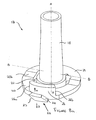
- the indexing mechanism 11 includes a drive coupling member 17 (most clearly shown in Figure 8a and 8b ) for selectively or temporarily coupling the actuator 14 to the indexing wheel 15 so that, when coupled, the indexing wheel 15 rotates in response to rotation of the actuator 14 to index the strip.
- the drive coupling member 17 comprises a shaft 18 defining an axis of rotation "A" (see Figure 8a and 8b ) on which the indexing wheel 15 is rotatably received so that it can rotate freely about the shaft 18 about said axis of rotation "A".
- the actuator 14 is fixedly attached to the drive coupling member 17 (such as by a splined pin - not shown) - that is inserted through the actuator 14, through an aperture 12a (see Figure 7 ) in the housing 12 and is received within the opening 18a in the shaft 18) so that the drive coupling member 17 rotates together with the actuator 14 at all times.
- the actuator 14, drive coupling member 17 and indexing wheel 15 are all mounted coaxially for rotation about the same axis "A".
- the drive coupling member 17 has a circular flange 19 that extends radially from one end of the shaft 18. A portion 20 of the flange is cut-away (see arcuate opening 21 in Figure 8 ) over an angle of approximately 180 degrees where the flange 19 joins the shaft 18 so that this portion 20 of the flange 19 is not directly attached to the shaft 18 but only to the remaining portion of the flange 19 at each of its ends 20a, 20b.
- this portion 20 of the flange 19 is flexible relative to the rest of the flange 19 and can be deflected out of the plane of the flange 19 that extends at right angles to the axis of the shaft, in an axial direction (indicated by "T” and "S", in Figure 8 and Figure 8b ) either towards or away from the shaft 18 or, more importantly, towards or away from the indexing wheel 15 which is mounted on the shaft 18, when force is applied to it.
- This flexible flange portion 20 hinges about an axis B which intersects the axis A of the shaft 18 and actuator 14 but extends at right angles to it.
- the drive coupling member 17, or at least the flange 19, is made from a resilient material so that when the deflected flexible flange portion 20 is released, it returns to its neutral, unstressed position, in which it lies coplanar with the remaining fixed portion of the flange 19.
- the flexible flange portion 20 has an integrally formed flange deflecting dog 22 projecting radially from its circumferential edge.
- the flange deflecting dog 22 has first and second angled engaging faces 23,24 on opposite sides.
- first or second angled engaging faces 23,24 cooperate with a fixed formation 25 on the housing 12 to cause the flexible flange portion 20 to deflect in a first direction.
- the other angled engaging face cooperates with the formation 25 on the housing 12 to cause the flexible flange portion 20 to deflect in a second, opposite direction, as will be explained in more detail below.
- the flexible flange portion 20 also has an arcuately shaped indexing wheel drive dog 26 that upstands in an axial direction from its surface towards the indexing wheel 15 in the same direction as the shaft 18 and extends partially around the circumference of the flexible flange portion 20.
- an end face 26a (see Figure 8a ) of the indexing wheel drive dog 26 engages a vane 15a,15b,15c,15d of the indexing wheel 15 when the flexible flange portion 20 has been deflected in a first direction, as indicated by arrow "T" in Figure 8b (the flexible flange portion 20 is shown in its deflected position in Figure 8b ), so that the indexing wheel 15 is driven together with the drive coupling member 17.
- the flange deflecting dog 22 engages a formation 25 on the housing 12 when the drive coupling member rotates in response to rotation of the actuator 14 so as to flex the deflectable portion of the flange 19.
- This formation 25 comprises first and second arcuately shaped tracks or paths 27, 28 positioned one above the other or spaced from each other in the axial direction.
- the surface of the innermost track 27 is visible in Figure 1 .
- the lower or outermost track 28 is located beneath it and is visible in Figure 7 .
- the ends of the tracks 27a, 28a have angled faces for reasons that will become apparent.
- the flange deflecting dog 22 falls off the surface of the track 27 and the resilience of the flexible flange portion 20 causes it to return to its original unstressed or neutral position.
- the indexing wheel drive dog 26 no longer engages with the vane 15c of the indexing wheel 15 and instead passes beneath it so the indexing wheel 15 remains stationary. Therefore, drive to the indexing wheel 15 is disengaged, despite continued rotation of the actuator 14 in the same direction.
- the flange deflecting dog 22 would simply engage against the end of the formation 25 in the housing 12 when rotated back in the opposite direction, thereby preventing rotation in the opposite direction or, the flange deflecting dog 22 would travel back over the innermost track 27 deflecting the flexible flange portion 20 in the same direction causing the opposite end 26b of the indexing wheel drive dog 26 to engage with a vane 15b of the indexing wheel 15 thereby driving the indexing wheel 15 backwards rather than leaving it stationary with no drive engaged. Therefore, it is necessary to ensure that the flexible flange portion 20 is deflected in the opposite direction, i.e.
- the indexing mechanism 11 also includes means for locking the indexing wheel 15 to prevent its rotation between indexing steps and means for temporarily releasing that lock to allow rotation of the indexing wheel 15 when driven by the indexing wheel drive dog 26.
- the lock also improves positional accuracy of the strip and, more specifically, the next blister to be pierced. This locking element will now be described in more detail below.
- the blister location chassis 13 comprises a resiliently flexible cantilever arm 30 that extends from the body of the chassis towards the indexing wheel 15.
- the free end of the cantilever arm 30 has an enlarged head portion 31 comprising a letterbox shaped slot, window or opening 32 in which the head 16c of a vane 15c of the indexing wheel 15 is located.
- the opening 32 is dimensioned such that the head 16c of the vane 15c (as shown in Figure 1 ) is a snug fit therein so that rotation of the indexing wheel 15 is prevented.
- the head 16c of a vane 15c is located in said opening 32 in the cantilever arm 30 of the chassis 13 so that rotation of the indexing wheel 15 is prevented.
- the indexing wheel drive dog 26 When the actuator 14 is rotated and the flange drive dog 22 engages the innermost track 27 so as to deflect the flexible portion 20 of the flange 19 inwardly towards the indexing wheel 15, the indexing wheel drive dog 26 initially engages with a protrusion 31a from the enlarged head portion 31 on the cantilever arm 30 of the blister location chassis 13 so that the cantilever arm 30 is deflected outwardly, away from the indexing wheel 15, to free the head 16c of the vane 15c from the opening 32, thereby unlocking the indexing wheel 15.
- the indexing wheel drive dog 26 no longer pushes against the cantilever arm 30 and so the cantilever arm 30 is free to move back towards the indexing wheel 15.
- the cantilever arm 30 is prevented from moving all the way back by the head 16b of a following vane 15b which contacts the cantilever arm 30.
- the head 16b slides across the cantilever arm and then drops into the opening 32 thereby allowing the cantilever arm 30 to move all the way back and locking the indexing wheel 15 in position prior to any further rotation of the drive coupling member 17 in response to continued rotation of the actuator 14.
- the extent of rotation of the indexing wheel 15 relative to the extent of rotation of the actuator 14 may be controlled by altering the circumferential length of the inner and outer tracks 27,28. If the tracks are made longer, the flexible flange portion 20 will be deflected for a greater proportion of the angle through which the actuator 14 is rotated and so the indexing wheel drive dog 26 will be engaged with the indexing wheel 15 to rotate the indexing wheel 15 throughout that angle. If required, the tracks 27,28 could be made sufficiently long so that the indexing wheel 15 rotates during rotation of the actuator 14 through its entire angle of movement in one direction. Alternatively, the tracks 27,28 could be made shorter to reduce the angle through which the actuator 14 and indexing wheel 15 rotate together.
- the track length can be selected so that the indexing wheel 15 is rotated through a sufficient angle to move the next, unused blister, into alignment with the blister piercing element, any further rotation of the actuator 14 can either be lost motion, i.e. it performs no function or some other function. For example, if it is the cap that is rotated, this last period of rotation of the cap can operate a separate actuator to cause it to pierce the lid of said blister that has just been moved into alignment with the blister piercing element.
- the indexing mechanism 11 is designed to enable a stroke to be aborted when the actuator 14 or cap has been rotated through an angle which is sufficient to cause initial indexing of the strip but which is not such that the drive to the indexing wheel 15 has disengaged, i.e. a position in which the flange deflecting dog 22 has not reached the end of the innermost track 27. If the stroke is aborted and the actuator 14 returned to its rest position before drive to the indexing wheel 15 has disengaged, the strip will be driven backwards into its original position as a rear surface 26b of the indexing wheel drive dog 26 will engage a preceding vane 15b to drive the indexing wheel 15 in the opposite direction. It will be appreciated that this has the advantage that the user may partially open the actuator 14 to enable them to inspect and/or clean a mouthpiece and then close it again without having indexed the strip or pierced a blister.
- the flange 19 is provided with a downwardly depending lug 19a (see Figure 8b ) that engages with a feature (not shown) on the casework when the actuator or cap has reached its fully open extent, thereby preventing any further rotation of the actuator or cap.
- the inhalation device of the present invention may be used in conjunction with a spiral wound element and/or a fixed or flexible wall separating a chamber containing unused blisters from a chamber that receives the used blisters.
Landscapes
- Health & Medical Sciences (AREA)
- Engineering & Computer Science (AREA)
- Life Sciences & Earth Sciences (AREA)
- Anesthesiology (AREA)
- General Health & Medical Sciences (AREA)
- Biomedical Technology (AREA)
- Heart & Thoracic Surgery (AREA)
- Hematology (AREA)
- Bioinformatics & Cheminformatics (AREA)
- Animal Behavior & Ethology (AREA)
- Pulmonology (AREA)
- Public Health (AREA)
- Veterinary Medicine (AREA)
- Biophysics (AREA)
- Medical Preparation Storing Or Oral Administration Devices (AREA)
- Medicinal Preparation (AREA)
- Infusion, Injection, And Reservoir Apparatuses (AREA)
- Medicines That Contain Protein Lipid Enzymes And Other Medicines (AREA)
Claims (21)
- Inhalator, umfassend ein Gehäuse (12) zur Aufnahme eines Streifens mit einer Vielzahl von Blistern, wobei jeder Blister einen durchbrechbaren Deckel aufweist und eine Dosis eines Medikaments zur Inhalation durch einen Anwender enthält, ein in dem Gehäuse (12) angebrachtes Indexierrad (15), das zum Antreiben eines Streifens drehbar ist, um Blister sequentiell in Ausrichtung mit einem Blister-Durchstechelement zu bewegen, ein Steuerelement (14), das drehbar in dem Gehäuse (12) angebracht ist, und einen Antriebsmechanismus mit einem Antriebskupplungselement (17) zur selektiven Verbindung des Steuerelements (14) mit dem Indexierrad (15), so dass sich das Indexierrad (15), wenn es verbunden ist, als Reaktion auf eine Drehung des Steuerelements (14) zum Indexieren des Streifens dreht, wobei das Antriebskupplungselement (17) zur Verbindung des Steuerelements (14) mit dem Indexierrad (15) während eines Teils der Drehung des Steuerelements (14) durch einen Anwender ausgebildet ist, so dass sich das Indexierrad (15) zusammen mit dem Steuerelement (14) dreht, wobei das Indexierrad (15) drehbar an dem Antriebskupplungselement (17) angebracht ist, dadurch gekennzeichnet, dass das Antriebskupplungselement (17) einen Indexierrad-Mitnehmer (26) umfasst, wobei der Antriebsmechanismus Mittel zur Bewegung, bei der Drehung des Steuerelements (14) und des Antriebskupplungselements (17), des Indexierrad-Mitnehmers (26) in eine Stellung, in der er mit dem Indexierrad (15) zusammenarbeitet, damit sich das Indexierrad (15) zusammen mit dem Steuerelement (14) und dem Antriebskupplungselement (17) bewegt, aufweist.
- Inhalator nach Anspruch 1, wobei sich das Steuerelement (14) zu dem Gehäuse (12) um eine Achse dreht und der Antriebsmechanismus ein Antriebskupplungselement (17) in dem Gehäuse (12) zur Drehung um dieselbe Achse umfasst.
- Inhalator nach Anspruch 2, wobei das Antriebskupplungselement (17) eine Welle (18) mit einer Achse, koaxial mit der Achse des Steuerelements (14), aufweist, wobei das Indexierrad (15) zur Drehung um diese Achse auf der Welle (18) angebracht ist.
- Inhalator nach einem der vorhergehenden Ansprüche, wobei das Antriebskupplungselement (17) aus einem nachgiebigen Material geformt ist und das Mittel zur Bewegung des Indexierrad-Mitnehmers (26) in eine Stellung, in der er mit dem Indexierrad (15) zusammenarbeitet, den Indexierrad-Mitnehmer (26) gegen eine Vorspannung bewegt, die durch die Nachgiebigkeit bereitgestellt wird.
- Inhalator nach Anspruch 4, wobei das Antriebskupplungselement (17) einen Flansch (19) umfasst, der sich radial von einem Ende der Welle (18) über ein Ende des Indexierrads (15) erstreckt.
- Inhalator nach Anspruch 5, wobei der Flansch (19) einen flexiblen Flanschabschnitt (20) aufweist, der sich relativ zu dem restlichen Abschnitts des Flansches (19) um eine Achse, die sich im Wesentlichen rechtwinklig zu der Achse der Welle (18) erstreckt, nachgiebig umbiegt oder biegt.
- Inhalator nach Anspruch 6, wobei der Flansch (19) eine bogenförmige Ausschnittregion (21) aufweist, die so ausgebildet ist, dass der flexible Flanschabschnitt (20) nur mit dem restlichen Abschnitt des Flansches (19) an jedem Ende verbunden ist.
- Inhalator nach Anspruch 7, wobei der flexible Flanschabschnitt (20) an dem restlichen Abschnitt des Flansches (19) an jedem Ende gelenkig befestigt ist.
- Inhalator nach einem der Ansprüche 6 bis 8, wobei der Indexierrad-Mitnehmer (26) von einer Oberfläche des flexiblen Flanschabschnitts (20) in eine Richtung zum Indexierrad (15) hin vorsteht.
- Inhalator nach Anspruch 9, wobei das Mittel zur Bewegung des Indexierrad-Mitnehmers (26) in eine Stellung, in der er mit dem Indexierrad (15) zusammenarbeitet, damit sich das Indexierrad (15) zusammen mit dem Steuerelement (14) bewegt, einen Flansch-Ablenkmitnehmer (22) umfasst, der von dem flexiblen Flanschabschnitt (20) vorragt.
- Inhalator nach Anspruch 10, wobei das Mittel zur Bewegung des Indexierrad-Mitnehmers (26) in eine Stellung, in der er mit dem Indexierrad (15) zusammenarbeitet, auch eine bogenförmige Führungsbahn (27, 28) in dem Gehäuse (12)umfasst, wobei die bogenförmige Führungsbahn (27, 28) eine erste Führungsfläche aufweist, so dass, wenn das Antriebskupplungselement (17) als Reaktion auf eine Drehung des Steuerelements (14) in eine erste Richtung gedreht wird, der Flansch-Ablenkmitnehmer (22) mit der ersten Führungsfläche zusammenarbeitet, um den flexiblen Flanschabschnitt (20) zu dem Indexierrad (15) abzulenken, so dass der Indexierrad-Mitnehmer (26) mit dem Indexierrad (15) zusammenarbeitet, um das Indexierrad (15) zusammen mit dem Antriebskupplungselement (17) zu drehen.
- Inhalator nach Anspruch 11, wobei die bogenförmige Führungsbahn (27, 28) so ausgebildet ist, dass der Flansch-Ablenkmitnehmer (22) von der ersten Führungsfläche herunterfällt, bevor das Steuerelement (14) bis zu seinem maximalem Ausmaß gedreht wurde, wobei die Nachgiebigkeit des flexiblen Flanschabschnitts (20) dazu führt, dass er in seinen ursprünglichen nicht abgelenkten Zustand zurückkehrt, so dass der Indexierrad-Mitnehmer (26) nicht mehr mit dem Indexierrad (15) zusammenarbeitet, wobei das Indexierrad (15) nun während der fortgesetzten Drehung des Steuerelements (14) und des Antriebskupplungselements (17) bis zu seinem maximalen Ausmaß stationär bleibt.
- Inhalator nach Anspruch 11 oder Anspruch 12, wobei die bogenförmige Führungsbahn (27, 28) eine zweite Führungsfläche umfasst, so dass, wenn der Flansch-Ablenkmitnehmer (22) von der ersten Führungsfläche heruntergefallen ist und das Antriebskupplungselement (17) als Reaktion auf eine Drehung des Steuerelements (14) in eine umgekehrte Richtung bewegt wird, der Flansch-Ablenkmitnehmer (22) mit der zweiten Führungsfläche zusammenarbeitet, so dass der flexible Flanschabschnitt (20) in die entgegengesetzte Richtung, weg vom Indexierrad (15), abgelenkt wird.
- Inhalator nach Anspruch 13, wobei der Flansch-Ablenkmitnehmer (22) eine erste zusammenwirkende Fläche (23) für den Eingriff mit der ersten Führungsfläche der bogenförmigen Führungsbahn (27, 28) und eine zweite zusammenwirkende Fläche (24) für den Eingriff mit der zweiten Führungsfläche der bogenförmigen Führungsbahn (27, 28) umfasst.
- Inhalator nach Anspruch 14, wobei sich die ersten und zweiten Führungsflächen der bogenförmigen Führungsbahn (27, 28) parallel zueinander, aber im Abstand voneinander in einer axialen Richtung erstrecken.
- Inhalator nach Anspruch 15, wobei die ersten und zweiten Führungsflächen abgewinkelte Endregionen (27a, 28a) aufweisen, so dass der Flansch-Ablenkmitnehmer (22) auf den abgewinkelten Endregionen (27a, 28a) auf jeweilige Führungsflächen der Führungsbahn (27, 28) hochrutscht.
- Inhalator nach einem der vorhergehenden Ansprüche, wobei das Indexierrad (15) eine Vielzahl von Flügeln (15a, 15b, 15c, 15d) umfasst und der Indexierrad-Mitnehmer (26) einen der Flügel (15a, 15b, 15c, 15d) berührt, wenn der Indexierrad-Mitnehmer (26) in eine Stellung bewegt wird, in der er mit dem Indexierrad (15) zusammenarbeitet, damit sich das Indexierrad (15) zusammen mit dem Antriebskupplungselement (17) und dem Steuerelement (14) bewegt.
- Inhalator nach einem der vorhergehenden Ansprüche, umfassend ein Arretierungselement (30, 31, 32) zur Verhinderung einer Drehung des Indexierrads (15) außer während der Zusammenarbeit des Indexierrad-Mitnehmers (26) mit dem Indexierrad (15).
- Inhalator nach Anspruch 18, wobei das Arretierungselement (30, 31, 32) einen Kragarm (30) umfasst, der in dem Gehäuse (12) angebracht ist und dessen freies Ende gegen das Indexierrad (15) vorgespannt ist, wobei das freie Ende des Kragarms (30) mit dem Indexierrad (15) zusammenarbeitet, um eine Drehung des Indexierrads (15) zu verhindern.
- Inhalator nach Anspruch 19, wobei das freie Ende des Kragarms (30) so ausgebildet ist, dass, wenn der Indexierrad-Mitnehmer (26) zum Indexierrad (15) bewegt wird, eine weitere Drehung des Antriebskupplungselements (17) dazu führt, dass der Indexierrad-Mitnehmer (26) in das freie Ende des Kragarms (30) eingreift und diesen aus seinem arretierenden Eingriff mit dem Indexierrad (15) vor der Zusammenarbeit mit dem Indexierrad (15) zur Drehung des Indexierrads (15) ablenkt.
- Inhalator nach Anspruch 20, wobei der Indexierrad-Mitnehmer (26) das freie Ende des Kragarms (30) aus dem Eingriff löst, wenn sich der Indexierrad-Mitnehmer (26) von dem Indexierrad (15) weg bewegt, so dass sich das freie Ende des Kragarms (30) zurück zum Indexierrad (15) bewegt, um das Indexierrad (15) in seiner Stellung zu arretieren.
Priority Applications (1)
| Application Number | Priority Date | Filing Date | Title |
|---|---|---|---|
| EP09703440.9A EP2254632B1 (de) | 2008-01-24 | 2009-01-14 | Inhalator |
Applications Claiming Priority (3)
| Application Number | Priority Date | Filing Date | Title |
|---|---|---|---|
| EP08100892A EP2082771A1 (de) | 2008-01-24 | 2008-01-24 | Inhalator |
| PCT/EP2009/050344 WO2009092652A1 (en) | 2008-01-24 | 2009-01-14 | Inhaler |
| EP09703440.9A EP2254632B1 (de) | 2008-01-24 | 2009-01-14 | Inhalator |
Publications (2)
| Publication Number | Publication Date |
|---|---|
| EP2254632A1 EP2254632A1 (de) | 2010-12-01 |
| EP2254632B1 true EP2254632B1 (de) | 2015-12-16 |
Family
ID=39522067
Family Applications (2)
| Application Number | Title | Priority Date | Filing Date |
|---|---|---|---|
| EP08100892A Withdrawn EP2082771A1 (de) | 2008-01-24 | 2008-01-24 | Inhalator |
| EP09703440.9A Active EP2254632B1 (de) | 2008-01-24 | 2009-01-14 | Inhalator |
Family Applications Before (1)
| Application Number | Title | Priority Date | Filing Date |
|---|---|---|---|
| EP08100892A Withdrawn EP2082771A1 (de) | 2008-01-24 | 2008-01-24 | Inhalator |
Country Status (18)
| Country | Link |
|---|---|
| US (2) | US8701661B2 (de) |
| EP (2) | EP2082771A1 (de) |
| JP (1) | JP5318119B2 (de) |
| KR (1) | KR101512476B1 (de) |
| CN (1) | CN101977646B (de) |
| AR (1) | AR070243A1 (de) |
| AU (1) | AU2009207760B2 (de) |
| BR (1) | BRPI0906367B8 (de) |
| CA (1) | CA2713006C (de) |
| ES (1) | ES2564181T3 (de) |
| IL (1) | IL207159A (de) |
| MX (1) | MX2010008070A (de) |
| NZ (1) | NZ586977A (de) |
| RU (1) | RU2481861C2 (de) |
| SG (1) | SG187460A1 (de) |
| TW (1) | TWI494142B (de) |
| WO (1) | WO2009092652A1 (de) |
| ZA (1) | ZA201005623B (de) |
Families Citing this family (11)
| Publication number | Priority date | Publication date | Assignee | Title |
|---|---|---|---|---|
| GB201020130D0 (en) | 2010-11-26 | 2011-01-12 | Vectura Delivery Devices Ltd | Inhaler |
| US8763608B2 (en) | 2008-10-09 | 2014-07-01 | Vectura Delivery Devices Limited | Inhaler |
| TR200907917A2 (tr) * | 2009-10-20 | 2011-05-23 | Bi̇lgi̇ç Mahmut | Kuru toz inhaleri. |
| KR101357262B1 (ko) | 2010-08-13 | 2014-01-29 | 주식회사 팬택 | 필터 정보를 이용한 객체 인식 장치 및 방법 |
| GB2502350A (en) * | 2012-05-25 | 2013-11-27 | Vectura Delivery Devices Ltd | Inhaler having means to control the force applied to an actuating lever |
| EP2878326A1 (de) | 2013-11-27 | 2015-06-03 | Vectura Delivery Devices Limited | Inhalator |
| RU2557962C1 (ru) * | 2014-07-03 | 2015-07-27 | Искандар Халиуллович Исмагилов | Фармацевтическая композиция на основе метизопринола для перорального введения |
| JP6619078B2 (ja) | 2015-07-20 | 2019-12-11 | ヴェクトュラ・デリヴァリー・ディヴァイスィズ・リミテッド | ドライパウダー吸入器 |
| RU2682966C1 (ru) * | 2018-03-20 | 2019-03-25 | Общество С Ограниченной Ответственностью "Валента - Интеллект" | Комбинации буспирона для лечения головокружения |
| US12214121B2 (en) * | 2018-09-17 | 2025-02-04 | Vectura Delivery Devices Limited | Dry powder inhaler |
| CN115916305B (zh) * | 2020-03-25 | 2025-03-21 | 陆品公司 | 多载体药物分配器 |
Family Cites Families (26)
| Publication number | Priority date | Publication date | Assignee | Title |
|---|---|---|---|---|
| YU48707B (sh) * | 1990-03-02 | 1999-07-28 | Glaxo Group Limited | Aparat za inhaliranje - inhalator |
| SK280968B6 (sk) * | 1990-03-02 | 2000-10-09 | Glaxo Group Limited | Balenie medikamentu na použite v inhalačnom prístroji |
| GB9016789D0 (en) * | 1990-07-31 | 1990-09-12 | Lilly Industries Ltd | Medicament administering devices |
| DE19523516C1 (de) * | 1995-06-30 | 1996-10-31 | Asta Medica Ag | Inhalator zum Verabreichen von Medikamenten aus Blisterpackungen |
| EP1219609B1 (de) | 1999-09-16 | 2007-04-04 | Tanabe Seiyaku Co., Ltd. | Aromatische stickstoffhältige sechs-ring-verbindungen |
| UA75375C2 (en) | 2000-10-12 | 2006-04-17 | Boehringer Ingelheim Pharma | Method for producing powdery preparations for inhaling |
| DE10050994A1 (de) | 2000-10-14 | 2002-04-18 | Boehringer Ingelheim Pharma | Neue als Arneimittel einsetzbare Anticholinergika sowie Verfahren zu deren Herstellung |
| DE10050995A1 (de) | 2000-10-14 | 2002-04-18 | Boehringer Ingelheim Pharma | Neue Anticholinergika, Verfahren zu deren Herstellung und deren Verwendung als Arzneimittel |
| DE10141376A1 (de) | 2001-08-23 | 2003-03-13 | Boehringer Ingelheim Pharma | Verfahren zur Herstellung von Inhalationspulvern |
| DE10141377A1 (de) | 2001-08-23 | 2003-03-13 | Boehringer Ingelheim Pharma | Aufstreuverfahren zur Herstellung von Pulverformulierungen |
| GB0125134D0 (en) * | 2001-10-19 | 2001-12-12 | Glaxo Group Ltd | Medicament dispenser |
| DE10203741A1 (de) | 2002-01-31 | 2003-08-14 | Boehringer Ingelheim Pharma | Neue Fluorencarbonsäureester, Verfahren zu deren Herstellung sowie deren Verwendung als Arzneimittel |
| DE10203749A1 (de) | 2002-01-31 | 2003-08-14 | Boehringer Ingelheim Pharma | Neue Anticholinergika, Verfahren zu deren Herstellung sowie deren Verwendung als Arzneimittel |
| DE10203753A1 (de) | 2002-01-31 | 2003-08-14 | Boehringer Ingelheim Pharma | Neue Xanthencarbonsäureester, Verfahren zu deren Herstellung sowie deren Verwendung als Arzneimittel |
| GB2407042B (en) | 2003-10-17 | 2007-10-24 | Vectura Ltd | Inhaler |
| GB0418278D0 (en) * | 2004-08-16 | 2004-09-15 | Glaxo Group Ltd | Medicament dispenser |
| GB0509952D0 (en) * | 2005-05-16 | 2005-06-22 | Glaxo Group Ltd | Fault indicator |
| GB0515584D0 (en) * | 2005-07-28 | 2005-09-07 | Glaxo Group Ltd | Medicament dispenser |
| MX2008009325A (es) * | 2006-02-20 | 2008-12-18 | Boehringer Ingelheim Int | Inhalador. |
| DE102006023662A1 (de) * | 2006-05-18 | 2007-11-22 | Boehringer Ingelheim Pharma Gmbh & Co. Kg | Inhalator |
| GB0622827D0 (en) * | 2006-11-15 | 2006-12-27 | Glaxo Group Ltd | Sheet driver for use in a drug dispenser |
| EP2011537A1 (de) | 2007-07-06 | 2009-01-07 | Vectura Delivery Devices Limited | Inhalator |
| EP2011538B1 (de) | 2007-07-06 | 2016-02-17 | Vectura Delivery Devices Limited | Inhalator |
| US20090164287A1 (en) | 2007-12-24 | 2009-06-25 | Kies Jonathan K | Method and apparatus for optimizing presentation of media content on a wireless device based on user behavior |
| US8763608B2 (en) * | 2008-10-09 | 2014-07-01 | Vectura Delivery Devices Limited | Inhaler |
| GB201020130D0 (en) * | 2010-11-26 | 2011-01-12 | Vectura Delivery Devices Ltd | Inhaler |
-
2008
- 2008-01-24 EP EP08100892A patent/EP2082771A1/de not_active Withdrawn
-
2009
- 2009-01-14 AU AU2009207760A patent/AU2009207760B2/en active Active
- 2009-01-14 CA CA2713006A patent/CA2713006C/en active Active
- 2009-01-14 EP EP09703440.9A patent/EP2254632B1/de active Active
- 2009-01-14 KR KR1020107018504A patent/KR101512476B1/ko active Active
- 2009-01-14 JP JP2010543464A patent/JP5318119B2/ja active Active
- 2009-01-14 NZ NZ586977A patent/NZ586977A/xx unknown
- 2009-01-14 ES ES09703440.9T patent/ES2564181T3/es active Active
- 2009-01-14 BR BRPI0906367A patent/BRPI0906367B8/pt active IP Right Grant
- 2009-01-14 MX MX2010008070A patent/MX2010008070A/es active IP Right Grant
- 2009-01-14 US US12/864,154 patent/US8701661B2/en active Active
- 2009-01-14 SG SG2013002449A patent/SG187460A1/en unknown
- 2009-01-14 CN CN2009801101825A patent/CN101977646B/zh active Active
- 2009-01-14 WO PCT/EP2009/050344 patent/WO2009092652A1/en not_active Ceased
- 2009-01-14 RU RU2010135349/14A patent/RU2481861C2/ru active
- 2009-01-23 AR ARP090100213A patent/AR070243A1/es active IP Right Grant
- 2009-01-23 TW TW098102956A patent/TWI494142B/zh active
-
2010
- 2010-07-22 IL IL207159A patent/IL207159A/en active IP Right Grant
- 2010-08-05 ZA ZA2010/05623A patent/ZA201005623B/en unknown
-
2014
- 2014-03-05 US US14/197,465 patent/US9919116B2/en active Active
Also Published As
| Publication number | Publication date |
|---|---|
| EP2082771A1 (de) | 2009-07-29 |
| HK1149912A1 (en) | 2011-10-21 |
| IL207159A (en) | 2013-03-24 |
| KR20100118119A (ko) | 2010-11-04 |
| BRPI0906367B8 (pt) | 2021-05-25 |
| TW200946154A (en) | 2009-11-16 |
| JP2011509779A (ja) | 2011-03-31 |
| BRPI0906367B1 (pt) | 2019-07-02 |
| AR070243A1 (es) | 2010-03-25 |
| CA2713006A1 (en) | 2009-07-30 |
| TWI494142B (zh) | 2015-08-01 |
| CN101977646A (zh) | 2011-02-16 |
| RU2481861C2 (ru) | 2013-05-20 |
| ZA201005623B (en) | 2018-11-28 |
| US20140182588A1 (en) | 2014-07-03 |
| MX2010008070A (es) | 2010-10-04 |
| SG187460A1 (en) | 2013-02-28 |
| KR101512476B1 (ko) | 2015-04-15 |
| WO2009092652A1 (en) | 2009-07-30 |
| NZ586977A (en) | 2013-01-25 |
| BRPI0906367A2 (pt) | 2016-04-26 |
| EP2254632A1 (de) | 2010-12-01 |
| ES2564181T3 (es) | 2016-03-18 |
| CN101977646B (zh) | 2013-06-26 |
| CA2713006C (en) | 2016-04-05 |
| US8701661B2 (en) | 2014-04-22 |
| AU2009207760A1 (en) | 2009-07-30 |
| US9919116B2 (en) | 2018-03-20 |
| AU2009207760B2 (en) | 2015-01-29 |
| JP5318119B2 (ja) | 2013-10-16 |
| RU2010135349A (ru) | 2012-02-27 |
| US20110030683A1 (en) | 2011-02-10 |
| IL207159A0 (en) | 2010-12-30 |
Similar Documents
| Publication | Publication Date | Title |
|---|---|---|
| EP2254632B1 (de) | Inhalator | |
| US8931480B2 (en) | Inhaler with drive gear outside of the housing | |
| US10183133B2 (en) | Inhaler | |
| US8763608B2 (en) | Inhaler | |
| WO2013175177A1 (en) | Inhaler | |
| EP2082770A1 (de) | Inhalator | |
| HK1149912B (en) | Inhaler | |
| AU2014253494B2 (en) | Inhaler | |
| HK1261478A1 (en) | Inhaler | |
| HK1261478B (en) | Inhaler | |
| HK1209065B (en) | Inhaler | |
| HK1197586B (en) | Inhaler | |
| HK1203424B (en) | Inhaler |
Legal Events
| Date | Code | Title | Description |
|---|---|---|---|
| PUAI | Public reference made under article 153(3) epc to a published international application that has entered the european phase |
Free format text: ORIGINAL CODE: 0009012 |
|
| 17P | Request for examination filed |
Effective date: 20100819 |
|
| AK | Designated contracting states |
Kind code of ref document: A1 Designated state(s): AT BE BG CH CY CZ DE DK EE ES FI FR GB GR HR HU IE IS IT LI LT LU LV MC MK MT NL NO PL PT RO SE SI SK TR |
|
| AX | Request for extension of the european patent |
Extension state: AL BA RS |
|
| DAX | Request for extension of the european patent (deleted) | ||
| REG | Reference to a national code |
Ref country code: HK Ref legal event code: DE Ref document number: 1149912 Country of ref document: HK |
|
| 17Q | First examination report despatched |
Effective date: 20130212 |
|
| GRAP | Despatch of communication of intention to grant a patent |
Free format text: ORIGINAL CODE: EPIDOSNIGR1 |
|
| INTG | Intention to grant announced |
Effective date: 20150626 |
|
| GRAP | Despatch of communication of intention to grant a patent |
Free format text: ORIGINAL CODE: EPIDOSNIGR1 |
|
| INTG | Intention to grant announced |
Effective date: 20150827 |
|
| GRAS | Grant fee paid |
Free format text: ORIGINAL CODE: EPIDOSNIGR3 |
|
| GRAA | (expected) grant |
Free format text: ORIGINAL CODE: 0009210 |
|
| AK | Designated contracting states |
Kind code of ref document: B1 Designated state(s): AT BE BG CH CY CZ DE DK EE ES FI FR GB GR HR HU IE IS IT LI LT LU LV MC MK MT NL NO PL PT RO SE SI SK TR |
|
| REG | Reference to a national code |
Ref country code: GB Ref legal event code: FG4D |
|
| REG | Reference to a national code |
Ref country code: CH Ref legal event code: EP |
|
| REG | Reference to a national code |
Ref country code: IE Ref legal event code: FG4D |
|
| REG | Reference to a national code |
Ref country code: AT Ref legal event code: REF Ref document number: 765225 Country of ref document: AT Kind code of ref document: T Effective date: 20160115 |
|
| REG | Reference to a national code |
Ref country code: FR Ref legal event code: PLFP Year of fee payment: 8 |
|
| REG | Reference to a national code |
Ref country code: DE Ref legal event code: R096 Ref document number: 602009035225 Country of ref document: DE |
|
| GRAT | Correction requested after decision to grant or after decision to maintain patent in amended form |
Free format text: ORIGINAL CODE: EPIDOSNCDEC |
|
| RAP2 | Party data changed (patent owner data changed or rights of a patent transferred) |
Owner name: VECTURA DELIVERY DEVICES LIMITED |
|
| REG | Reference to a national code |
Ref country code: ES Ref legal event code: FG2A Ref document number: 2564181 Country of ref document: ES Kind code of ref document: T3 Effective date: 20160318 |
|
| REG | Reference to a national code |
Ref country code: SE Ref legal event code: TRGR |
|
| REG | Reference to a national code |
Ref country code: NO Ref legal event code: T2 Effective date: 20151216 |
|
| REG | Reference to a national code |
Ref country code: NL Ref legal event code: MP Effective date: 20151216 |
|
| REG | Reference to a national code |
Ref country code: LT Ref legal event code: MG4D |
|
| PG25 | Lapsed in a contracting state [announced via postgrant information from national office to epo] |
Ref country code: LT Free format text: LAPSE BECAUSE OF FAILURE TO SUBMIT A TRANSLATION OF THE DESCRIPTION OR TO PAY THE FEE WITHIN THE PRESCRIBED TIME-LIMIT Effective date: 20151216 Ref country code: HR Free format text: LAPSE BECAUSE OF FAILURE TO SUBMIT A TRANSLATION OF THE DESCRIPTION OR TO PAY THE FEE WITHIN THE PRESCRIBED TIME-LIMIT Effective date: 20151216 |
|
| REG | Reference to a national code |
Ref country code: HK Ref legal event code: GR Ref document number: 1149912 Country of ref document: HK |
|
| PG25 | Lapsed in a contracting state [announced via postgrant information from national office to epo] |
Ref country code: BE Free format text: LAPSE BECAUSE OF NON-PAYMENT OF DUE FEES Effective date: 20160131 Ref country code: NL Free format text: LAPSE BECAUSE OF FAILURE TO SUBMIT A TRANSLATION OF THE DESCRIPTION OR TO PAY THE FEE WITHIN THE PRESCRIBED TIME-LIMIT Effective date: 20151216 Ref country code: FI Free format text: LAPSE BECAUSE OF FAILURE TO SUBMIT A TRANSLATION OF THE DESCRIPTION OR TO PAY THE FEE WITHIN THE PRESCRIBED TIME-LIMIT Effective date: 20151216 Ref country code: LV Free format text: LAPSE BECAUSE OF FAILURE TO SUBMIT A TRANSLATION OF THE DESCRIPTION OR TO PAY THE FEE WITHIN THE PRESCRIBED TIME-LIMIT Effective date: 20151216 |
|
| REG | Reference to a national code |
Ref country code: GR Ref legal event code: EP Ref document number: 20160400491 Country of ref document: GR Effective date: 20160505 |
|
| PG25 | Lapsed in a contracting state [announced via postgrant information from national office to epo] |
Ref country code: CZ Free format text: LAPSE BECAUSE OF FAILURE TO SUBMIT A TRANSLATION OF THE DESCRIPTION OR TO PAY THE FEE WITHIN THE PRESCRIBED TIME-LIMIT Effective date: 20151216 |
|
| PG25 | Lapsed in a contracting state [announced via postgrant information from national office to epo] |
Ref country code: PT Free format text: LAPSE BECAUSE OF FAILURE TO SUBMIT A TRANSLATION OF THE DESCRIPTION OR TO PAY THE FEE WITHIN THE PRESCRIBED TIME-LIMIT Effective date: 20160418 Ref country code: RO Free format text: LAPSE BECAUSE OF FAILURE TO SUBMIT A TRANSLATION OF THE DESCRIPTION OR TO PAY THE FEE WITHIN THE PRESCRIBED TIME-LIMIT Effective date: 20151216 Ref country code: EE Free format text: LAPSE BECAUSE OF FAILURE TO SUBMIT A TRANSLATION OF THE DESCRIPTION OR TO PAY THE FEE WITHIN THE PRESCRIBED TIME-LIMIT Effective date: 20151216 Ref country code: IS Free format text: LAPSE BECAUSE OF FAILURE TO SUBMIT A TRANSLATION OF THE DESCRIPTION OR TO PAY THE FEE WITHIN THE PRESCRIBED TIME-LIMIT Effective date: 20160416 Ref country code: SK Free format text: LAPSE BECAUSE OF FAILURE TO SUBMIT A TRANSLATION OF THE DESCRIPTION OR TO PAY THE FEE WITHIN THE PRESCRIBED TIME-LIMIT Effective date: 20151216 Ref country code: LU Free format text: LAPSE BECAUSE OF FAILURE TO SUBMIT A TRANSLATION OF THE DESCRIPTION OR TO PAY THE FEE WITHIN THE PRESCRIBED TIME-LIMIT Effective date: 20160114 |
|
| REG | Reference to a national code |
Ref country code: DE Ref legal event code: R097 Ref document number: 602009035225 Country of ref document: DE |
|
| PG25 | Lapsed in a contracting state [announced via postgrant information from national office to epo] |
Ref country code: MC Free format text: LAPSE BECAUSE OF FAILURE TO SUBMIT A TRANSLATION OF THE DESCRIPTION OR TO PAY THE FEE WITHIN THE PRESCRIBED TIME-LIMIT Effective date: 20151216 |
|
| PLBE | No opposition filed within time limit |
Free format text: ORIGINAL CODE: 0009261 |
|
| STAA | Information on the status of an ep patent application or granted ep patent |
Free format text: STATUS: NO OPPOSITION FILED WITHIN TIME LIMIT |
|
| PG25 | Lapsed in a contracting state [announced via postgrant information from national office to epo] |
Ref country code: PL Free format text: LAPSE BECAUSE OF FAILURE TO SUBMIT A TRANSLATION OF THE DESCRIPTION OR TO PAY THE FEE WITHIN THE PRESCRIBED TIME-LIMIT Effective date: 20151216 Ref country code: DK Free format text: LAPSE BECAUSE OF FAILURE TO SUBMIT A TRANSLATION OF THE DESCRIPTION OR TO PAY THE FEE WITHIN THE PRESCRIBED TIME-LIMIT Effective date: 20151216 |
|
| 26N | No opposition filed |
Effective date: 20160919 |
|
| PG25 | Lapsed in a contracting state [announced via postgrant information from national office to epo] |
Ref country code: BE Free format text: LAPSE BECAUSE OF FAILURE TO SUBMIT A TRANSLATION OF THE DESCRIPTION OR TO PAY THE FEE WITHIN THE PRESCRIBED TIME-LIMIT Effective date: 20151216 |
|
| REG | Reference to a national code |
Ref country code: FR Ref legal event code: PLFP Year of fee payment: 9 |
|
| PG25 | Lapsed in a contracting state [announced via postgrant information from national office to epo] |
Ref country code: SI Free format text: LAPSE BECAUSE OF FAILURE TO SUBMIT A TRANSLATION OF THE DESCRIPTION OR TO PAY THE FEE WITHIN THE PRESCRIBED TIME-LIMIT Effective date: 20151216 |
|
| PG25 | Lapsed in a contracting state [announced via postgrant information from national office to epo] |
Ref country code: MT Free format text: LAPSE BECAUSE OF FAILURE TO SUBMIT A TRANSLATION OF THE DESCRIPTION OR TO PAY THE FEE WITHIN THE PRESCRIBED TIME-LIMIT Effective date: 20151216 |
|
| REG | Reference to a national code |
Ref country code: FR Ref legal event code: PLFP Year of fee payment: 10 |
|
| PG25 | Lapsed in a contracting state [announced via postgrant information from national office to epo] |
Ref country code: HU Free format text: LAPSE BECAUSE OF FAILURE TO SUBMIT A TRANSLATION OF THE DESCRIPTION OR TO PAY THE FEE WITHIN THE PRESCRIBED TIME-LIMIT; INVALID AB INITIO Effective date: 20090114 Ref country code: CY Free format text: LAPSE BECAUSE OF FAILURE TO SUBMIT A TRANSLATION OF THE DESCRIPTION OR TO PAY THE FEE WITHIN THE PRESCRIBED TIME-LIMIT Effective date: 20151216 |
|
| PG25 | Lapsed in a contracting state [announced via postgrant information from national office to epo] |
Ref country code: MT Free format text: LAPSE BECAUSE OF FAILURE TO SUBMIT A TRANSLATION OF THE DESCRIPTION OR TO PAY THE FEE WITHIN THE PRESCRIBED TIME-LIMIT Effective date: 20160131 Ref country code: TR Free format text: LAPSE BECAUSE OF FAILURE TO SUBMIT A TRANSLATION OF THE DESCRIPTION OR TO PAY THE FEE WITHIN THE PRESCRIBED TIME-LIMIT Effective date: 20151216 Ref country code: MK Free format text: LAPSE BECAUSE OF FAILURE TO SUBMIT A TRANSLATION OF THE DESCRIPTION OR TO PAY THE FEE WITHIN THE PRESCRIBED TIME-LIMIT Effective date: 20151216 |
|
| PG25 | Lapsed in a contracting state [announced via postgrant information from national office to epo] |
Ref country code: BG Free format text: LAPSE BECAUSE OF FAILURE TO SUBMIT A TRANSLATION OF THE DESCRIPTION OR TO PAY THE FEE WITHIN THE PRESCRIBED TIME-LIMIT Effective date: 20151216 |
|
| REG | Reference to a national code |
Ref country code: AT Ref legal event code: UEP Ref document number: 765225 Country of ref document: AT Kind code of ref document: T Effective date: 20151216 |
|
| P01 | Opt-out of the competence of the unified patent court (upc) registered |
Effective date: 20230418 |
|
| PGFP | Annual fee paid to national office [announced via postgrant information from national office to epo] |
Ref country code: CH Payment date: 20250201 Year of fee payment: 17 Ref country code: GR Payment date: 20250129 Year of fee payment: 17 |
|
| REG | Reference to a national code |
Ref country code: CH Ref legal event code: U11 Free format text: ST27 STATUS EVENT CODE: U-0-0-U10-U11 (AS PROVIDED BY THE NATIONAL OFFICE) Effective date: 20260201 |
|
| PGFP | Annual fee paid to national office [announced via postgrant information from national office to epo] |
Ref country code: SE Payment date: 20260127 Year of fee payment: 18 |
|
| PGFP | Annual fee paid to national office [announced via postgrant information from national office to epo] |
Ref country code: GB Payment date: 20260127 Year of fee payment: 18 |
|
| PGFP | Annual fee paid to national office [announced via postgrant information from national office to epo] |
Ref country code: ES Payment date: 20260202 Year of fee payment: 18 |
|
| PGFP | Annual fee paid to national office [announced via postgrant information from national office to epo] |
Ref country code: NO Payment date: 20260128 Year of fee payment: 18 Ref country code: IE Payment date: 20260127 Year of fee payment: 18 Ref country code: DE Payment date: 20260128 Year of fee payment: 18 |
|
| PGFP | Annual fee paid to national office [announced via postgrant information from national office to epo] |
Ref country code: AT Payment date: 20260128 Year of fee payment: 18 |
|
| PGFP | Annual fee paid to national office [announced via postgrant information from national office to epo] |
Ref country code: IT Payment date: 20260121 Year of fee payment: 18 |
|
| PGFP | Annual fee paid to national office [announced via postgrant information from national office to epo] |
Ref country code: FR Payment date: 20260126 Year of fee payment: 18 |