EP2259989B1 - Belt - Google Patents
Belt Download PDFInfo
- Publication number
- EP2259989B1 EP2259989B1 EP09719510A EP09719510A EP2259989B1 EP 2259989 B1 EP2259989 B1 EP 2259989B1 EP 09719510 A EP09719510 A EP 09719510A EP 09719510 A EP09719510 A EP 09719510A EP 2259989 B1 EP2259989 B1 EP 2259989B1
- Authority
- EP
- European Patent Office
- Prior art keywords
- belt
- composition
- fabric
- fabric layer
- lubricant
- Prior art date
- Legal status (The legal status is an assumption and is not a legal conclusion. Google has not performed a legal analysis and makes no representation as to the accuracy of the status listed.)
- Active
Links
Images


Classifications
-
- B—PERFORMING OPERATIONS; TRANSPORTING
- B65—CONVEYING; PACKING; STORING; HANDLING THIN OR FILAMENTARY MATERIAL
- B65G—TRANSPORT OR STORAGE DEVICES, e.g. CONVEYORS FOR LOADING OR TIPPING, SHOP CONVEYOR SYSTEMS OR PNEUMATIC TUBE CONVEYORS
- B65G15/00—Conveyors having endless load-conveying surfaces, i.e. belts and like continuous members, to which tractive effort is transmitted by means other than endless driving elements of similar configuration
- B65G15/30—Belts or like endless load-carriers
- B65G15/32—Belts or like endless load-carriers made of rubber or plastics
- B65G15/34—Belts or like endless load-carriers made of rubber or plastics with reinforcing layers, e.g. of fabric
-
- B—PERFORMING OPERATIONS; TRANSPORTING
- B65—CONVEYING; PACKING; STORING; HANDLING THIN OR FILAMENTARY MATERIAL
- B65G—TRANSPORT OR STORAGE DEVICES, e.g. CONVEYORS FOR LOADING OR TIPPING, SHOP CONVEYOR SYSTEMS OR PNEUMATIC TUBE CONVEYORS
- B65G15/00—Conveyors having endless load-conveying surfaces, i.e. belts and like continuous members, to which tractive effort is transmitted by means other than endless driving elements of similar configuration
- B65G15/30—Belts or like endless load-carriers
- B65G15/32—Belts or like endless load-carriers made of rubber or plastics
- B65G15/38—Belts or like endless load-carriers made of rubber or plastics with flame-resistant layers, e.g. of asbestos, glass
-
- B—PERFORMING OPERATIONS; TRANSPORTING
- B65—CONVEYING; PACKING; STORING; HANDLING THIN OR FILAMENTARY MATERIAL
- B65G—TRANSPORT OR STORAGE DEVICES, e.g. CONVEYORS FOR LOADING OR TIPPING, SHOP CONVEYOR SYSTEMS OR PNEUMATIC TUBE CONVEYORS
- B65G2201/00—Indexing codes relating to handling devices, e.g. conveyors, characterised by the type of product or load being conveyed or handled
- B65G2201/02—Articles
- B65G2201/0264—Luggage
Definitions
- This invention relates generally to a belt assembly, and more particularly to a lubricated belt for use in applications such as conveying systems, according to the preamble of claim 1 as disclosed in US-A-2004/0132586 .
- Conveying systems are used in a number of applications, particularly material handling, package handling and sortation, and the like.
- One such application is baggage conveying systems in airports.
- a conveying system generally comprises an endless belt having a top, or outer, surface and a bottom, or inner, surface; guide rollers around which the belt passes; and spaced support rollers for supporting the belt.
- the belt is driven, directly or indirectly, by a motor so that the bottom surface of the belt slides across the rollers.
- the support rollers are replaced by a stationary slider bed, or deck, for supporting the belt.
- the bottom surface of the belt slides across the upper surface of the slider bed, which is typically formed from steel or other rigid material.
- An endless belt may be made by joining opposite ends of a belt material.
- Belts are often given a one or two-sided coating to provide certain desirable characteristics to the belt. Accordingly, different materials with different characteristics may be used for the coating. For example, various thermoplastic materials, such as PVC or polyurethane, are used for coating a belt for use in conveying systems.
- the action of the belt passing over the rollers or across the slider bed generates friction between the bottom surface of the belt and the surfaces of the rollers or the slider bed. Efforts have been made to reduce this friction in order to reduce the power consumption required to drive the belt, friction-induced heating, and friction-induced noise. Reducing the friction can also enhance the operational life of the belt. It is known to reduce the friction of a belt through the use of lubrication on the bottom surface of the belt, and there are several known lubricants and associated methods. The underlying construction of the belt can also affect the resulting friction.
- belts for use in certain applications must meet defined durability and flammability criteria.
- a belt for use in an airport baggage conveyor system must be puncture and tear resistant and non-flammable.
- the defined criteria and test methods for belts in the U.S. are specified in ASTM D 378, "Standard Test Methods For Rubber (Elastomeric) Belting, Flat Type", which covers the procedures for evaluating the physical properties of flat conveyor belting, including flammability. Similar criteria have been established by the International Standards Organization and are specified in ISO 340, "Conveyor Belt - Laboratory Scale Flammability Characteristics-Requirements and Test Methods". Meeting the flammability requirement of ASTM D 378 or ISO 340 necessitates applying a flame retardant coating to the belt. However, it has been found that the non-flammable coating can prevent absorption of lubricant coatings.
- a belt assembly is provided for use as an endless belt as stated in the appended claim 1.
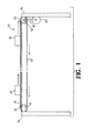
- FIG. 1 is a schematic side elevational view of a portion of a conveying system generally designated at 10.
- the conveying system 10 includes an endless belt 12 that passes around a pair of guide rollers 14 rotatably mounted at each end of a frame 16 for carrying the belt 12.
- the belt 12 is endless by virtue of opposite ends of the belt being joined together at a joint, which is preferably in the form of a splice (not shown).
- the belt 12 is typically substantially uniform along its length except for at the joint.
- the belt 12 can be a variety of different lengths and can also be a variety of different widths, which is the distance between side edges of the belt 12.
- the length of the belt 12 is preferably many times greater than the width.
- FIG. 2 there is shown a schematic partial view of a longitudinally extending portion of the upper run of the belt 12 according to the present invention.
- the belt 12 includes a top ply 24 and a bottom ply 26 joined by an intermediate layer 30 therebetween.
- the upper surface of the top ply 24 is substantially planar and is defined by a flame retardant polyvinyl chloride (PVC) coating 25 that is adhered to and covers the top ply 24.
- PVC polyvinyl chloride
- the top ply 24 may further comprise a friction surface (not shown) for moving objects on an incline.
- the bottom ply 26 includes a bottom surface 27 which slides across the slider bed 15 and around the guide rollers 14 ( FIG. 1 ).
- the bottom surface 27 is preferably substantially planar, except for the texture of the fabric of the bottom ply 26 and any discontinuity in the region of the joint. As will be more fully described herein, the construction of the bottom ply 26 provides a low coefficient of friction as against the guide rollers 14 and the slider bed 15.
- the intermediate layer 30 is disposed between and joins the top ply 24 and the bottom ply 26.
- the intermediate layer comprises a flame retardant PVC adhesive coating 32 adhered to the inner surface of the top ply 24.
- a polyurethane adhesive coating 34 is adhered to the inner surface of the bottom ply 26.
- a middle layer comprising a flame retardant PVC layer 36 is disposed between the two adhesive coatings 32, 34.
- the middle layer PVC coating 36 is about 0.5 mm thick and functions to separate the top ply 24 and the bottom ply 26 and further provides lateral stiffness and puncture and tear resistance to the belt 12 construction.
- the belt 12 includes a lubricant coating composition 40 that is impregnated in the bottom ply 26 and is proximate the bottom surface 27 of the bottom ply 26.
- the lubricant coating composition 40 is schematically illustrated by stippling (i.e., dots and flicks) in the bottom ply 26.
- FIG. 3 diagrammatically illustrates a method and apparatus for forming an endless belt 12 according to an embodiment of the present invention.
- a roll 44 of belt material 46 is provided, for example, a woven polyester fabric for forming the top ply 24.
- the belt material 46 is unwound from the roll 44 by one or more transport mechanisms 48 arranged along the travel path of the belt material 46.
- the belt material 46 is initially passed through a coater 50.
- a coater 50 Any type of suitable coater known in the art of wide web or textile coating may be used. Exemplary coaters include knife coaters, roll coaters, and the like.
- a liquid PVC plastisol primer 25 is applied to (e.g., poured onto, or the like) the upper surface of the fabric of the top ply 24 of the belt material 46.
- the PVC plastisol primer 25 also contains a flame retardant such as antimony trioxidc and aluminum trihydrate, although other suitable flame retardants are available including phosphoric acid ester plasticizer, brominated flame retardant and the like, and an isocyanate bonding agent.
- the purpose of the PVC plastisol primer 25 is to protect the polyester fabric from burning, and also to act as an adhesive layer for a second, cover coating which may be applied later.
- the PVC plastisol primer 25 also contains pigment and acts as the carrying surface of the finished belt. More particularly, the PVC plastisol primer 25 is applied at a position just upstream from a nip defined between an upper knife edge and a lower roller. The liquid of the coating composition is forced into the fabric of the top ply 24 of the belt material 46 as it passes through the nip.
- the belt material 46 with the liquid PVC plastisol primer is cured by transporting the belt material through a drying oven 52 suspended in a tenter frame, or the like.
- the belt material 46 is then transported through a cooling mechanism 54, where the now coated belt material 56 is cooled, such as by nipping the coated belt material between chilled rollers.
- the coated belt material 56 is then formed into a roll 57.
- the fabric of the top ply 24 receives the same PVC plastisol primer 32 on the bottom, or inner, surface.
- the purpose of this coating of PVC plastisol primer 32 is, again, to protect the polyester fabric from burning and to act as an adhesive layer between the top ply 24 fabric and the intermediate layer 30.
- the method of applying the second coating of PVC plastisol primer 32 is the same as described above, beginning with the roll of belt material 44. However, in this pass through the apparatus, the belt material 46 is of course already coated on one side with the PVC plastisol primer 25.
- a second roll 44 of belt material 46 for example, woven polyester fabric, is provided for forming the bottom ply 26.
- the belt material 46 is unwound from the roll 44 by the one or more transport mechanisms 48 and passed through the coater 50.
- a liquid, solvent-based polyurethane primer 34 is applied to the top, or inner, surface of the fabric of the bottom ply 26 of the belt material 46.
- the polyurethane primer 34 acts as an adhesive layer between the bottom ply 26 and the intermediate layer 30.
- a flame retardant additive to the polyurethane primer 34 is optional.
- the belt material 46 of the bottom ply 26 is cured by transporting through the drying oven 52 suspended in a tenter frame, or the like.
- the belt material 46 of the bottom ply 26 is then transported through the cooling mechanism 54, where the now coated belt material 56 is cooled, such as by nipping the coated belt material between chilled rollers.
- the coated belt material 56 is then formed into a roll 57.
- the coated top ply 24 and the coated bottom ply 26 are laminated together using a PVC plastisol 36 including a flame retardant.
- the liquid PVC plastisol 36 is applied to the primer-coated inner surface of either the top ply 24 or the bottom ply 26.
- the other of the top ply 24 or the bottom ply 26 is then nipped onto the coated fabric ply and passed through the drying oven 52 to cure and solidify the PVC plastisol 36 layer thus forming, for example, a two-ply belt.
- the polyurethane coating 34 on the inner surface of the bottom ply 26 serves as a barrier coating, preventing significant penetration or absorption of the PVC plastisols 32, 36 of the intermediate layer 30 into the bottom ply 26. This allows the fabric of the bottom ply 26 to remain "open” so that a lubricant coating composition 40 applied to the bottom surface 27 of the bottom ply 26 can substantially fill the interstices between the fibers of the fabric.
- the belt 12 is run upside down through the apparatus, such that the bottom surface 27 of the bottom ply 26 of the belt 12 is facing upward, since this surface will eventually contact the slider bed 15 and guide rollers 14.
- a liquid lubricant composition 40 is applied to the bottom surface 27 of the bottom ply 26 at a position just upstream from the nip so that the liquid lubricant composition 40 is forced into the fabric of the bottom ply 26 as it passes through the nip.
- the belt with the liquid lubricant composition is cured by transporting through the drying oven 52 suspended in the tenter frame, or the like.
- the oven curing of the lubricant coating dries any solvent or water, and also melts the solid component of the lubricant composition 40 allowing the lubricant to flow into the spaces in the fabric of the bottom ply 26. Volatilization of the solvent component of the lubricant composition 40 in the drying oven 52 results in an at least substantially solid lubricant coating 40 being impregnated in the bottom ply 26 of the belt 12.
- the dwell time for each incremental portion of the belt 12 within the drying oven 52 is about 1 to 5 minutes, or more specifically about 2 minutes, and the temperature within the oven is about 80° to 200°C, or more specifically about 100°C.
- the belt 12 is then transported through the cooling mechanism 54 and formed into a roll 57. Thereafter, and in some cases at a different facility, the coated belt material 56 is unwound from the roll 57 by one or more transport mechanisms 58 positioned along the travel path of the belt. At a cutting mechanism 60, sections of the belt material 62 are cut from the coated belt material 56. At a splicing mechanism 64, each of the sections of belt material 62 is joined end-to-end to form an endless belt, as is known in the art. Most of the joints, or splices, in belts used in airport baggage conveying systems will be metal lacing. The splice may extend at an oblique angle relative to the longitudinally extending edges of the belt 12. The belt 12 is preferably substantially uniform along its length except for in the region of the splice.
- additional coatings of PVC, or other polymer can be applied over the PVC primer coating 25 on the upper surface of the top ply 24 in order to act as a carrying surface.
- Various properties, such as high friction coefficient, abrasion resistance, or texture can be imparted into this top coating, depending on the specific function of the belt 12.
- a soft PVC coating with longitudinal grooves might be used for incline conveyors, in order to have a sufficiently high friction coefficient to elevate goods without slippage relative to the top surface.
- fabric made from other fibers such as nylon, aramide, cotton or other materials could be used, and the coatings could be made from polyurethane, polyethylene, silicone rubber, or other suitable materials.
- the belt 12 includes three main layers: the top ply 24, the bottom ply 26, and an intermediate layer 30.
- the top ply 24 is preferably a plainly woven fabric.
- the top ply 24 may be formed of any woven fabric exhibiting sufficient durability and flexibility for an intended application.
- the top ply fabric is designed to be tear and puncture resistant.
- woven fabric formed from polyester yarns, particularly multifilament polyester yarns having a denier of about 1000, is suitable
- the term "yarn" refers to any continuous strand of textile fibers, filaments or material in a form suitable for knitting, weaving, or otherwise intertwining to form a textile fabric.
- the fabrics of the belt 12 are constructed solely of man-made filaments or fibers, although natural fibers may be used in alternative embodiments.
- the fabric construction of the top ply 24 is a plain weave, including thirty-four (34) 2,000 denier polyester multifilament warp yarns per 25.4 mm (inch) of belt width and 25.4 0.4 mm diameter polyester monofilament weft yarns per 25.4 mm (inch) of belt length.
- This fabric construction provides a laterally stiff belt with high tear and yarns per 25.4 mm (inch) of belt length.
- This fabric construction provides a laterally stiff belt with high tear and puncture resistance. It is understood that weft-inserted or knitted fabrics could also be used according to other embodiments of the present invention.
- the bottom ply 26 may be formed from any fabric providing sufficient strength, durability and frictional properties to the resulting belt 12 construction.
- the fabric of the bottom ply 26 includes an effective amount of relatively fine or low twist warp yarns.
- warp yarn refers to those yarns within a given layer which extend in the longitudinal direction, that is, along the length of the belt 12.
- weft yarns refers to those yarns within a given layer that extend in a transverse direction, that is, across the belt 12.
- an effective amount of the warp yarns within the bottom ply 26 preferably have a relatively fine denier, such as a denier of less than about 1000, and, more preferably, a denier of about 500 or smaller.
- an effective amount of the warp yarns within the bottom ply 26 have a denier ranging from about 150 to 500.
- 100% of the warp yarns of the fabric of the bottom ply 26 are the relatively fine denier yarn.
- the warp yarns of the bottom ply 26 may possess low twist, such as a twist of less than about 2.5 complete turns per inch, and most preferably twist ranging from about 1.5 to 2.0 complete turns per 25.4 mm (inch). Regarding the warp yarns of the bottom ply 26, a twist of about 2.0 complete turns per 25.4 mm (inch) may be most preferred for facilitating weaving, whereas a twist of about 1.5 complete turns per 25.4 mm (inch) may be most preferred for reducing the friction generated between the bottom ply 26 and the slider bed (F1G. 1).
- the bottom ply 26 warp yarns preferably are formed from polyethylene terephthalate, they are about 500 denier or smaller, and each is twisted about 1.5 to 2.0 complete turns per 25.4 mm (inch).
- the bottom ply 26 weft yarns are preferably formed from polyester monofilament fiber, and the monofilament weft yarns each preferably have a diameter of about 0.2 mm.
- the fabric of the bottom ply 26 is preferably a 2/1 twill weave, wherein the warp yarn preferably passes under two weft yarns for every weft yarn it passes over, so that the long, floating portions of the warp yarns contact the slider bed 15 ( FIG.
- the bottom ply 136 fabric has 45x40 yarns per 25.4 mm (inch) (i.e., 45 warp ends per inch and 40 weft ends per 25.4 mm (inch).
- One exemplary commercially available fabric for use in the bottom ply 26 is Style Code No. 5522, produced by Milliken & Company of Spartanburg, S.C.
- the coefficient of friction between the bottom surface 27 of the belt 12 and the slider bed is preferably further reduced by an at least substantially solid lubricant composition 40 that is impregnated in the fabric of the bottom ply 26 and is proximate the bottom surface 27.
- solid means that the solvents employed within the corresponding liquid lubricant composition, from which the solid lubricant composition 40 has been formed, have been substantially removed, such as by volatization and the like.
- the solid lubricant composition 40 is preferably a mixture, and most preferably is a substantially uniformly dispersed mixture.
- the solid lubricant composition 40 is schematically illustrated by stippling (i.e., dots and flicks) in the bottom ply 26.
- the solid lubricant composition 40 preferably includes one or more higher viscosity lubricants, which may be a solid at room temperature, optionally along with one or more lower viscosity lubricants, which may be a liquid at room temperature, and optionally one or more binders, with the lower viscosity lubricant(s) having lower viscosity than the higher viscosity lubricant(s).
- Exemplary higher viscosity lubricants preferably include waxes, such as natural and synthetic waxes. Natural waxes include waxes derived from animal, vegetable and mineral sources, as well as mixtures thereof.
- the higher viscosity lubricant is a vegetable wax, such as carnauba wax, candelilla wax, bay berry wax, sugar cane wax and mixtures thereof.
- Synthetic waxes include, but are not limited to, halogenated waxes.
- fluorinated wax may improve the lubrication, heat stability, and flammability characteristics of the lubricant composition 40.
- the solid lubricant composition 40 preferably includes no more than about 60 weight percent of the higher viscosity lubricant, based on the weight of the solid lubricant composition ("bosc"). More specifically, the solid lubricant composition 40 preferably includes from about 30 weight percent to about 60 weight percent higher viscosity lubricant, bosc. Even more specifically, in accordance with the exemplary embodiment of the present invention, the solid lubricant composition 40 includes about 55 weight percent of the higher viscosity lubricant, bosc. In alternative embodiments, the solid lubricant composition includes about 52 weight percent of the higher viscosity lubricant, bosc.
- Suitable lower viscosity lubricants include silicones, mineral oils, polyglycols, and mixtures thereof.
- the lower viscosity lubricant includes one or more silicone lubricants.
- the silicone lubricant is a polysiloxane, particularly a polydimethlysiloxane.
- One exemplary silicone lubricant is Dow Coming 200 Fluid, commercially available from the Dow Coming Corporation of Midland Michigan. 200 Fluid is a liquid at room temperature.
- the lower viscosity lubricant can be included in any amount providing sufficient lubricity without detrimentally impacting the cohesion of the resulting solid lubricant composition 40.
- Lower viscosity lubricants preferably exhibit a lower coefficient of friction than higher viscosity lubricants.
- lower viscosity lubricants can impact coating cohesion and adhesive properties. Consequently, the solid lubricant composition 40 preferably includes significantly higher amounts of the higher viscosity lubricant than the lower viscosity lubricant.
- the weight ratio of the higher viscosity lubricant to lower viscosity lubricant may be 3:2 or lower. In one embodiment, the weight ratio of the higher viscosity lubricant to lower viscosity lubricant may be 1:1 or lower, such as a ratio of about 2:3:1.
- the solid lubricant composition 40 preferably includes comparable or even lower amounts of the higher viscosity lubricant than the lower viscosity lubricant.
- the weight ratio of the higher viscosity lubricant to lower viscosity lubricant may be 3:2 or lower. This weight ratio has been found to be effective for a lubricant composition comprising carnauba wax and Dow Coming 200 Fluid silicone in 100 centistoke viscosity.
- the weight ratio of the higher viscosity lubricant to lower viscosity lubricant may be 1:1 or lower, such as a ratio of about 2:3.
- the solid lubricant composition 40 preferably includes no more than about 60 weight percent of the lower viscosity lubricant, bosc. More specifically, the solid lubricant composition 40 preferably includes from about 10 weight percent to about 50 weight percent of the lower viscosity lubricant, bosc. Even more specifically, in accordance with the exemplary embodiment of the present invention, the solid lubricant composition 40 includes about 40 weight percent of the lower viscosity lubricant, bosc.
- the lubricant composition may further comprise surfactant and heat stabilizer.
- Surfactant may be present in an amount of about 8 weight percent of the surfactant, bosc.
- Stabilizer may be present in an amount of about 0.5 weight percent of the stabilizer, bosc.
- the optional binder within the solid lubricant composition 40 may serve as an adhesive agent to provide bonding of lubricant 40 to the fabric of the bottom ply 26, as well as binding silicone oil into the coating preventing migration.
- exemplary binders for use in the present invention include any film forming polymer known in the art that is compatible with the remaining components within the solid lubricant composition 40 and provides sufficient bonding properties and flexibility.
- Suitable binders include polyurethanes, acrylic polymers, vinyl polymers, and the like, including mixtures and copolymers thereof.
- the binder is preferably polyurethane.
- Suitable polyurethanes include both polyester polyurethanes and polyether polyurethanes.
- the polyurethane is a polyester polyurethane.
- One suitable commercially available polyester polyurethane is ESTANE.TM. 5712 F30 polyurethane from Nonwoven, Inc. of Cleveland, Ohio.
- the binder may be present in the solid lubricant composition 40 in any amount effective to provide sufficient bonding in the bottom ply 26.
- the binder may be present in the solid lubricant composition 40 in an amount ranging from about 10 to 50 weight percent, bosc.
- the solid lubricant composition 40 includes about 20 weight percent to about 30 weight percent binder, bosc. More preferably, the solid lubricant composition 40 includes from about 25 weight percent to about 30 weight percent binder, bosc, such as an amount of about 29 weight percent or about 28 weight percent.
- the solid lubricant composition may optionally further include one or more bonding agents, e.g. crosslinkers, to crosslink the binder and further promote cohesion within the solid lubricant composition 40 and adhesion in the bottom ply 26.
- bonding agents e.g. crosslinkers
- Any suitable crosslinker known in the art for use in conjunction with a given binder may be employed.
- Exemplary crosslinkers include isocyanates, such as polyisocyanates and diisocyantes, peroxides, epoxies, polyfunctional amides and mixtures thereof.
- a polyisocyanate crosslinking agent may be included in solid lubricant compositions employing a polyurethane binder.
- the crosslinker is included in the composition in amounts effective to provide a sufficient amount of crosslinking within the binder without imparting excessive stiffness to the resulting solid lubricant composition 40.
- the crosslinker is present in the solid lubricant composition in amounts ranging from about 2.5 to 10 weight percent, bose.
- the crosslinker is preferably present in an amount of about 4.9 weight percent, bosc.
- the solid lubricant composition 40 is formed from a liquid lubricant composition that is applied to, e.g. coated onto, the bottom ply 26 as a liquid lubricant composition.
- the solvents are then removed from the liquid lubricant composition, typically by drying and the like, resulting in a layer of the solid lubricant composition 40 substantially covering at least a portion of the outermost surface of, and substantially impregnated into, the fabric of the bottom ply 26.
- the liquid lubricant composition 40 may be formed by dispersing or dissolving appropriate amounts of the higher viscosity lubricant and the lower viscosity lubricant in a lubricant solvent.
- the higher viscosity lubricant and lower viscosity lubricant are normally incorporated into the liquid lubricant composition in an undiluted form.
- the optional binder composition preferably contains the binder polymer dispersed or dissolved in an appropriate binder solvent. Suitable binder solvents include polar organic solvents, such as acetone and methyl ethyl ketone ("MEK”) and mixtures thereof.
- the binder solvent is a mixture of acetone and MEK, particularly a mixture containing about 58 parts acetone per about 42 parts MEK.
- the lubricant solvent may be water, unless an isocyanate bonding agent is used.
- the lubricant solvent can also be any organic solvent capable of dispersing the higher and lower viscosity lubricants and binder composition.
- a suitable organic lubricant solvent is a ketone based solvent, such as cyclohexanone. It is understood that carnauba wax is highly insoluble such that the carnauba wax is emulsified rather than dissolved.
- the liquid lubricant composition is preferably formed by initially combining the higher and lower viscosity lubricants with the lubricant solvent and heating the initial mixture to an elevated temperature, such as a temperature of about 80°C. while the initial mixture is under low speed agitation. Upon dissolution of the higher viscosity lubricant, the initial mixture may be allowed to cool to a lower, yet elevated, temperature, such as a temperature of about 55°C. Upon cooling to the lower temperature, the optional binder composition may be added, after which the agitation speed may be increased and the liquid lubricant composition may be agitated for a period of about 5 minutes.
- the liquid lubricant composition is typically allowed to sit for at least 24 hours, after which the liquid lubricant composition is stirred and the viscosity is adjusted with an appropriate organic solvent, such as acetone.
- the viscosity of the liquid lubricant composition is preferably about 4000 cps (Brookfield viscosity based on a 20 rpm spindle speed).
- a bonding agent composition may be added to the liquid lubricant composition.
- the bonding agent composition preferably includes the crosslinker dissolved or suspended in an appropriate organic solvent.
- the bonding agent composition may include a polyisocyante crosslinking agent dissolved or suspended within ethyl acetate.
- One exemplary bonding agent composition is DESMODUR RC, commercially available from Bayer Corporation of Pittsburgh, Pa., which contains about 30% polyisocyanate in ethyl acetate.
- the bonding agent composition is preferably added to the liquid lubricating composition at room temperature under high speed agitation. The resulting liquid lubricant composition is allowed to agitate at least about 3 minutes prior to use.
- the shelf life of compositions containing bonding agents may be limited. Accordingly, the bonding agent composition may be added to the liquid lubricant composition either immediately prior to or a few hours before its application to the fabric of the bottom ply 26.
- the liquid lubricant composition is applied to the belt material using the equipment and processes described above. More particularly, a coater, such as a knife coater, is used to apply the liquid lubricant composition to the bottom ply of the belt material and the coated belt material is subsequently dried.
- the various solvents within the liquid lubricant composition are volatilized in the drying oven 52 ( FIG. 3 ) following the coating process, so that the resulting solid lubricant composition 40 solidifies in the fabric of the bottom ply 26.
- the solid lubricant composition 40 is preferably at least substantially in solid form at room temperature (e.g., 22.degree. C (72.degree. F.)).
- the coated belt 12 preferably has solid lubricant composition coat weight ranging from about 33.9 g/m 2 (1 oz/sq. yd) to about 169.5 g/m 2 (5 oz/sq. yd). Most preferably, the solid lubricant composition 40 is present in the belt 12 in an amount of about 72 g/m2 (2.1 oz/sq. yd).
- the belt lubricant 40 is at least substantially solid after drying, migration of the lubricant 40 is substantially precluded. Also, due to the substantially solid nature of the lubricant 40, it can advantageously be applied to rolls of belting material before sections are cut therefrom and spliced, because the solid lubricant does not substantially interfere with the splicing or adhesion. Additionally, the fabric of the bottom ply 26 may be saturated with the lubricant composition 40, with the lubricant composition intimately impregnated in the fabric bottom ply, and not just on the bottom surface, so that any loss of lubricant from the belt is insubstantial.
- the depth of absorption of the lubricant composition 40 into the bottom ply 26 may be controlled such that the solid lubricant composition 40 is not dispersed throughout the thickness of the fabric of the bottom ply 26. This may be accomplished during curing of the belt 12 by controlling the temperature of the oven and the dwell time within the oven after application of the liquid lubricant composition 40. Lower temperature or less dwell time will lessen the depth of absorption of the lubricant composition 40 into the fabric of the bottom ply 26. Another method of controlling the depth of absorption of the lubricant composition into the fabric is by controlling the solids content of the lubricant composition 40. Reducing the solids content of the lubricant composition 40 will lessen the depth of absorption into the bottom ply 26.
- the amount of binder will affect the rheology of the lubricant composition 40, which effects absorption into the fabric. Specifically, increasing the amount of binder in the lubricant composition 40 will lessen the depth of absorption into the bottom ply 26.
- the binder/bonding agent in the lubricant composition 40 substantially keeps the lubricant(s) on the belt 12 so that relubrication is not necessary.
- the low viscosity lubricant in the lubricant composition 40 improves lubrication, but the proportion is sufficiently small so that the lubricant composition 40 is still substantially solid at room temperature.
- the small proportion of low viscosity lubricant does not substantially migrate or substantially interfere with belt splicing.
- the endless belt as described herein, is used in conveyor systems. It is understood that the belt is not limited to the type of conveyor system 10 illustrated and described with reference to FIG. 1 , because the belt 12 of the present invention operates advantageously with a wide range of different types of conveyor systems, and can be used in a wide range of other applications in which belts are used. In one example, the endless belt is used in a treadmill with a waxed or unwaxed deck.
- the lubricant compositions described herein can be applied to many different types of belts, can be used on items other than belts, and can be considered to be isolated articles of manufacture (e.g., separate from any belts, conveyor systems, etc.)
- the lubricant 40 it is within the scope of the present embodiments for the lubricant 40 to be used with (e.g. applied to and preferably, impregnated into the bottom surfaces of) conventional conveyor system belts.
- the belt herein described can be used in combination with many different types of lubricants or can be considered to be isolated articles of manufacture (e.g., separate from any lubricant etc.).
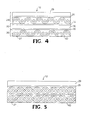
- FIGs. 4 and 5 there is shown schematic partial views of longitudinally extending portions of the upper runs of two other embodiments of the belt 12 according to the present invention. Both embodiments include the solid lubricant 40 incorporated into the bottom surface 27 of the belt 12. The depth of absorption of the lubricant composition 40 into the bottom ply 26 is not dispersed throughout the thickness of the fabric of the bottom ply 26.
- the embodiment of the belt 12 shown is similar to the belt described above, including a top ply 24 and a bottom ply 26 joined by an intermediate layer 30 therebetween.
- the upper surface of the top ply 24 further comprises an additional flame retardant polyvinyl chloride (PVC) coating 29 that covers the inner PVC coating 25.
- PVC polyvinyl chloride
- a flame retardant PVC coating 35 is adhered to the inner surface of the bottom ply 26, replacing the polyurethane adhesive coating 34 of the previously described embodiment. It is believed that the PVC coating 35 penetrates into the bottom ply 26 fabric whereas the polyurethane adhesive layer 34 does not, which may effect the depth of absorption of the lubricant 40 when using the PVC coating 35.
- the embodiment of the belt 12 shown is a single-ply fabric referred to as a doubled fabric, or a multi-weave.
- the fabric has a straight warp yarn that has no crimp for accommodating high tensile loads with low stitch.
- the weave pattern depicted may further reduce power consumption due to low bending resistance in the longitudinal direction.
Landscapes
- Engineering & Computer Science (AREA)
- Mechanical Engineering (AREA)
- Belt Conveyors (AREA)
- Laminated Bodies (AREA)
Description
- This invention relates generally to a belt assembly, and more particularly to a lubricated belt for use in applications such as conveying systems, according to the preamble of claim 1 as disclosed in
US-A-2004/0132586 . - Conveying systems are used in a number of applications, particularly material handling, package handling and sortation, and the like. One such application is baggage conveying systems in airports.
- A conveying system generally comprises an endless belt having a top, or outer, surface and a bottom, or inner, surface; guide rollers around which the belt passes; and spaced support rollers for supporting the belt. The belt is driven, directly or indirectly, by a motor so that the bottom surface of the belt slides across the rollers. In some conveying systems, such as systems for airport baggage handling, the support rollers are replaced by a stationary slider bed, or deck, for supporting the belt. The bottom surface of the belt slides across the upper surface of the slider bed, which is typically formed from steel or other rigid material.
- An endless belt may be made by joining opposite ends of a belt material. Belts are often given a one or two-sided coating to provide certain desirable characteristics to the belt. Accordingly, different materials with different characteristics may be used for the coating. For example, various thermoplastic materials, such as PVC or polyurethane, are used for coating a belt for use in conveying systems.
- The action of the belt passing over the rollers or across the slider bed generates friction between the bottom surface of the belt and the surfaces of the rollers or the slider bed. Efforts have been made to reduce this friction in order to reduce the power consumption required to drive the belt, friction-induced heating, and friction-induced noise. Reducing the friction can also enhance the operational life of the belt. It is known to reduce the friction of a belt through the use of lubrication on the bottom surface of the belt, and there are several known lubricants and associated methods. The underlying construction of the belt can also affect the resulting friction.
- In addition, belts for use in certain applications must meet defined durability and flammability criteria. For example, a belt for use in an airport baggage conveyor system must be puncture and tear resistant and non-flammable. The defined criteria and test methods for belts in the U.S. are specified in ASTM D 378, "Standard Test Methods For Rubber (Elastomeric) Belting, Flat Type", which covers the procedures for evaluating the physical properties of flat conveyor belting, including flammability. Similar criteria have been established by the International Standards Organization and are specified in ISO 340, "Conveyor Belt - Laboratory Scale Flammability Characteristics-Requirements and Test Methods". Meeting the flammability requirement of ASTM D 378 or ISO 340 necessitates applying a flame retardant coating to the belt. However, it has been found that the non-flammable coating can prevent absorption of lubricant coatings.
- For the foregoing reasons, there is a need for a belt with a reduced coefficient of friction for use, for example, in a conveyor system. The new belt should be able to meet desired criteria for operability and functionality in a preferred application.
- Accordingly, as described herein, a belt assembly is provided for use as an endless belt as stated in the appended claim 1.
- For a more complete understanding of the present invention, reference should now be had to the embodiments shown in the accompanying drawings and described below. In the drawings:
-
FIG. 1 is a schematic, side elevational view of a portion of an embodiment of a conveyor system for use with a belt according to an embodiment of the present invention. -
FIG. 2 is a schematic, elevational, partial view of a longitudinally extending portion of an upper run of a belt according to an embodiment of the present invention; -
FIG. 3 diagrammatically illustrates a method and apparatus for forming an endless belt from a roll of belt material according to the present invention; -
FIG. 4 is a schematic, elevational, partial view of a longitudinally extending portion of an upper run of a belt according to another embodiment of the present invention; and -
FIG. 5 is a schematic, elevational, partial view of a longitudinally extending portion of an upper run of a belt according to yet another embodiment of the present invention. - Certain terminology is used herein for convenience only and is not to be taken as a limitation on the invention. For example, words such as "upper," "lower," "left," "right," "horizontal," "vertical," "upward," and "downward" merely describe the configuration shown in the FIGs. Indeed, the components may be oriented in any direction and the terminology, therefore, should be understood as encompassing such variations unless specified otherwise.
- Referring now to the drawings, wherein like reference numerals designate corresponding or similar elements throughout the several views,
FIG. 1 is a schematic side elevational view of a portion of a conveying system generally designated at 10. Theconveying system 10 includes anendless belt 12 that passes around a pair ofguide rollers 14 rotatably mounted at each end of aframe 16 for carrying thebelt 12. Thebelt 12 is endless by virtue of opposite ends of the belt being joined together at a joint, which is preferably in the form of a splice (not shown). Thebelt 12 is typically substantially uniform along its length except for at the joint. Thebelt 12 can be a variety of different lengths and can also be a variety of different widths, which is the distance between side edges of thebelt 12. The length of thebelt 12 is preferably many times greater than the width. - As shown in
FIG. 1 , thebelt 12 extends around therollers 14 so that the bottom surface of the upper run of the belt engages aslider bed 15, and the upper surface of the upper run of the belt faces away from theslider bed 15. The upper surface of thebelt 12 is shown carryingbaggage 22, or the like, which contributes to the friction resulting from the bottom surface of thebelt 12 sliding across theslider bed 15. One of theguide rollers 14 is driven, such as via adrive belt 18, by amotor 20 that is mounted to theframe 16. The direction of movement of thebelt 12 is denoted by the arrows. It is understood that a variety of other types of mechanisms for driving thebelt 12 are also within the scope of the present invention. - Referring now to
FIG. 2 , there is shown a schematic partial view of a longitudinally extending portion of the upper run of thebelt 12 according to the present invention. Thebelt 12 includes atop ply 24 and a bottom ply 26 joined by anintermediate layer 30 therebetween. The upper surface of thetop ply 24 is substantially planar and is defined by a flame retardant polyvinyl chloride (PVC) coating 25 that is adhered to and covers thetop ply 24. Thetop ply 24 may further comprise a friction surface (not shown) for moving objects on an incline. - The bottom ply 26 includes a
bottom surface 27 which slides across theslider bed 15 and around the guide rollers 14 (FIG. 1 ). Thebottom surface 27 is preferably substantially planar, except for the texture of the fabric of the bottom ply 26 and any discontinuity in the region of the joint. As will be more fully described herein, the construction of the bottom ply 26 provides a low coefficient of friction as against theguide rollers 14 and theslider bed 15. - The
intermediate layer 30 is disposed between and joins thetop ply 24 and the bottom ply 26. The intermediate layer comprises a flame retardant PVCadhesive coating 32 adhered to the inner surface of thetop ply 24. A polyurethaneadhesive coating 34 is adhered to the inner surface of the bottom ply 26. A middle layer comprising a flameretardant PVC layer 36 is disposed between the twoadhesive coatings layer PVC coating 36 is about 0.5 mm thick and functions to separate thetop ply 24 and the bottom ply 26 and further provides lateral stiffness and puncture and tear resistance to thebelt 12 construction. - According to the present invention, the
belt 12 includes alubricant coating composition 40 that is impregnated in the bottom ply 26 and is proximate thebottom surface 27 of the bottom ply 26. InFIG. 2 , thelubricant coating composition 40 is schematically illustrated by stippling (i.e., dots and flicks) in the bottom ply 26. -
FIG. 3 diagrammatically illustrates a method and apparatus for forming anendless belt 12 according to an embodiment of the present invention. Aroll 44 ofbelt material 46 is provided, for example, a woven polyester fabric for forming thetop ply 24. Thebelt material 46 is unwound from theroll 44 by one ormore transport mechanisms 48 arranged along the travel path of thebelt material 46. - The
belt material 46 is initially passed through acoater 50. Any type of suitable coater known in the art of wide web or textile coating may be used. Exemplary coaters include knife coaters, roll coaters, and the like. In thecoater 50, a liquidPVC plastisol primer 25 is applied to (e.g., poured onto, or the like) the upper surface of the fabric of the top ply 24 of thebelt material 46. ThePVC plastisol primer 25 also contains a flame retardant such as antimony trioxidc and aluminum trihydrate, although other suitable flame retardants are available including phosphoric acid ester plasticizer, brominated flame retardant and the like, and an isocyanate bonding agent. The purpose of thePVC plastisol primer 25 is to protect the polyester fabric from burning, and also to act as an adhesive layer for a second, cover coating which may be applied later. In some cases, thePVC plastisol primer 25 also contains pigment and acts as the carrying surface of the finished belt. More particularly, thePVC plastisol primer 25 is applied at a position just upstream from a nip defined between an upper knife edge and a lower roller. The liquid of the coating composition is forced into the fabric of the top ply 24 of thebelt material 46 as it passes through the nip. - Thereafter, the
belt material 46 with the liquid PVC plastisol primer is cured by transporting the belt material through a drying oven 52 suspended in a tenter frame, or the like. Thebelt material 46 is then transported through a cooling mechanism 54, where the now coatedbelt material 56 is cooled, such as by nipping the coated belt material between chilled rollers. Thecoated belt material 56 is then formed into aroll 57. - Next the fabric of the
top ply 24 receives the samePVC plastisol primer 32 on the bottom, or inner, surface. The purpose of this coating ofPVC plastisol primer 32 is, again, to protect the polyester fabric from burning and to act as an adhesive layer between thetop ply 24 fabric and theintermediate layer 30. The method of applying the second coating ofPVC plastisol primer 32 is the same as described above, beginning with the roll ofbelt material 44. However, in this pass through the apparatus, thebelt material 46 is of course already coated on one side with thePVC plastisol primer 25. - A
second roll 44 ofbelt material 46, for example, woven polyester fabric, is provided for forming the bottom ply 26. Thebelt material 46 is unwound from theroll 44 by the one ormore transport mechanisms 48 and passed through thecoater 50. In thecoater 50, a liquid, solvent-basedpolyurethane primer 34 is applied to the top, or inner, surface of the fabric of the bottom ply 26 of thebelt material 46. Thepolyurethane primer 34 acts as an adhesive layer between the bottom ply 26 and theintermediate layer 30. A flame retardant additive to thepolyurethane primer 34 is optional. Thereafter, thebelt material 46 of the bottom ply 26 is cured by transporting through the drying oven 52 suspended in a tenter frame, or the like. Thebelt material 46 of the bottom ply 26 is then transported through the cooling mechanism 54, where the now coatedbelt material 56 is cooled, such as by nipping the coated belt material between chilled rollers. Thecoated belt material 56 is then formed into aroll 57. - Next, the coated
top ply 24 and the coated bottom ply 26 are laminated together using aPVC plastisol 36 including a flame retardant. Theliquid PVC plastisol 36 is applied to the primer-coated inner surface of either the top ply 24 or the bottom ply 26. The other of thetop ply 24 or the bottom ply 26 is then nipped onto the coated fabric ply and passed through the drying oven 52 to cure and solidify thePVC plastisol 36 layer thus forming, for example, a two-ply belt. Thepolyurethane coating 34 on the inner surface of the bottom ply 26 serves as a barrier coating, preventing significant penetration or absorption of the PVC plastisols 32, 36 of theintermediate layer 30 into the bottom ply 26. This allows the fabric of the bottom ply 26 to remain "open" so that alubricant coating composition 40 applied to thebottom surface 27 of the bottom ply 26 can substantially fill the interstices between the fibers of the fabric. - Following the lamination step, the
belt 12 is run upside down through the apparatus, such that thebottom surface 27 of the bottom ply 26 of thebelt 12 is facing upward, since this surface will eventually contact theslider bed 15 and guiderollers 14. In thecoater 50, aliquid lubricant composition 40 is applied to thebottom surface 27 of the bottom ply 26 at a position just upstream from the nip so that theliquid lubricant composition 40 is forced into the fabric of the bottom ply 26 as it passes through the nip. The belt with the liquid lubricant composition is cured by transporting through the drying oven 52 suspended in the tenter frame, or the like. - The oven curing of the lubricant coating dries any solvent or water, and also melts the solid component of the
lubricant composition 40 allowing the lubricant to flow into the spaces in the fabric of the bottom ply 26. Volatilization of the solvent component of thelubricant composition 40 in the drying oven 52 results in an at least substantiallysolid lubricant coating 40 being impregnated in the bottom ply 26 of thebelt 12. - The dwell time for each incremental portion of the
belt 12 within the drying oven 52 is about 1 to 5 minutes, or more specifically about 2 minutes, and the temperature within the oven is about 80° to 200°C, or more specifically about 100°C. - The
belt 12 is then transported through the cooling mechanism 54 and formed into aroll 57. Thereafter, and in some cases at a different facility, thecoated belt material 56 is unwound from theroll 57 by one or more transport mechanisms 58 positioned along the travel path of the belt. At acutting mechanism 60, sections of thebelt material 62 are cut from thecoated belt material 56. At asplicing mechanism 64, each of the sections ofbelt material 62 is joined end-to-end to form an endless belt, as is known in the art. Most of the joints, or splices, in belts used in airport baggage conveying systems will be metal lacing. The splice may extend at an oblique angle relative to the longitudinally extending edges of thebelt 12. Thebelt 12 is preferably substantially uniform along its length except for in the region of the splice. - It is understood that the process described above is merely exemplary and that a different sequence or additional process steps may be used during the manufacture of an endless belt according to the present invention. For example, additional coatings of PVC, or other polymer, can be applied over the
PVC primer coating 25 on the upper surface of thetop ply 24 in order to act as a carrying surface. Various properties, such as high friction coefficient, abrasion resistance, or texture can be imparted into this top coating, depending on the specific function of thebelt 12. For example, a soft PVC coating with longitudinal grooves might be used for incline conveyors, in order to have a sufficiently high friction coefficient to elevate goods without slippage relative to the top surface. Further, it is possible to use other materials than those described above. For example, fabric made from other fibers such as nylon, aramide, cotton or other materials could be used, and the coatings could be made from polyurethane, polyethylene, silicone rubber, or other suitable materials. - As described above, the
belt 12 according to the present invention includes three main layers: thetop ply 24, the bottom ply 26, and anintermediate layer 30. The top ply 24 is preferably a plainly woven fabric. The top ply 24 may be formed of any woven fabric exhibiting sufficient durability and flexibility for an intended application. For airport baggage handling, for example, the top ply fabric is designed to be tear and puncture resistant. In one embodiment woven fabric formed from polyester yarns, particularly multifilament polyester yarns having a denier of about 1000, is suitable As used herein, the term "yarn" refers to any continuous strand of textile fibers, filaments or material in a form suitable for knitting, weaving, or otherwise intertwining to form a textile fabric. In accordance with one embodiment of the present invention, all of the fabrics of thebelt 12 are constructed solely of man-made filaments or fibers, although natural fibers may be used in alternative embodiments. In one embodiment, the fabric construction of thetop ply 24 is a plain weave, including thirty-four (34) 2,000 denier polyester multifilament warp yarns per 25.4 mm (inch) of belt width and 25.4 0.4 mm diameter polyester monofilament weft yarns per 25.4 mm (inch) of belt length. This fabric construction provides a laterally stiff belt with high tear and yarns per 25.4 mm (inch) of belt length. This fabric construction provides a laterally stiff belt with high tear and puncture resistance. It is understood that weft-inserted or knitted fabrics could also be used according to other embodiments of the present invention. - The bottom ply 26 may be formed from any fabric providing sufficient strength, durability and frictional properties to the resulting
belt 12 construction. According to one embodiment of the present invention, the fabric of the bottom ply 26 includes an effective amount of relatively fine or low twist warp yarns. As used herein, the term "warp yarn" refers to those yarns within a given layer which extend in the longitudinal direction, that is, along the length of thebelt 12. Correspondingly, as used herein, the term "weft yarns" refers to those yarns within a given layer that extend in a transverse direction, that is, across thebelt 12. Although not wishing to be bound by theory, theoretically the incorporation of relatively fine or low twist warp yarn into the bottom ply 26 decreases the coefficient of friction between thebottom surface 27 of thebelt 12 and the slider bed 15 (FIG. 1 ). - Accordingly, an effective amount of the warp yarns within the bottom ply 26 preferably have a relatively fine denier, such as a denier of less than about 1000, and, more preferably, a denier of about 500 or smaller. As an additional example, an effective amount of the warp yarns within the bottom ply 26 have a denier ranging from about 150 to 500. According to one embodiment of the present invention, 100% of the warp yarns of the fabric of the bottom ply 26 are the relatively fine denier yarn.
- The warp yarns of the bottom ply 26 may possess low twist, such as a twist of less than about 2.5 complete turns per inch, and most preferably twist ranging from about 1.5 to 2.0 complete turns per 25.4 mm (inch). Regarding the warp yarns of the bottom ply 26, a twist of about 2.0 complete turns per 25.4 mm (inch) may be most preferred for facilitating weaving, whereas a twist of about 1.5 complete turns per 25.4 mm (inch) may be most preferred for reducing the friction generated between the bottom ply 26 and the slider bed (F1G. 1).
- According to the present invention, the bottom ply 26 warp yarns preferably are formed from polyethylene terephthalate, they are about 500 denier or smaller, and each is twisted about 1.5 to 2.0 complete turns per 25.4 mm (inch). The bottom ply 26 weft yarns are preferably formed from polyester monofilament fiber, and the monofilament weft yarns each preferably have a diameter of about 0.2 mm. The fabric of the bottom ply 26 is preferably a 2/1 twill weave, wherein the warp yarn preferably passes under two weft yarns for every weft yarn it passes over, so that the long, floating portions of the warp yarns contact the slider bed 15 (
FIG. 1 ) that the belt slides across, with the belt traveling in the direction in which the warp yarns extend. The bottom ply 136 fabric has 45x40 yarns per 25.4 mm (inch) (i.e., 45 warp ends per inch and 40 weft ends per 25.4 mm (inch). One exemplary commercially available fabric for use in the bottom ply 26 is Style Code No. 5522, produced by Milliken & Company of Spartanburg, S.C. - As mentioned above, the relatively fine size or the low twist of the warp yarns in the bottom ply 26 are believed to reduce friction between the
bottom surface 27 of thebelt 12 and the slider bed 15 (FIG. 1 ). According to the present invention, the coefficient of friction between thebottom surface 27 of thebelt 12 and the slider bed is preferably further reduced by an at least substantiallysolid lubricant composition 40 that is impregnated in the fabric of the bottom ply 26 and is proximate thebottom surface 27. As used herein, the term "solid" means that the solvents employed within the corresponding liquid lubricant composition, from which thesolid lubricant composition 40 has been formed, have been substantially removed, such as by volatization and the like. Thesolid lubricant composition 40 is preferably a mixture, and most preferably is a substantially uniformly dispersed mixture. InFIG. 2 , thesolid lubricant composition 40 is schematically illustrated by stippling (i.e., dots and flicks) in the bottom ply 26. - The
solid lubricant composition 40 preferably includes one or more higher viscosity lubricants, which may be a solid at room temperature, optionally along with one or more lower viscosity lubricants, which may be a liquid at room temperature, and optionally one or more binders, with the lower viscosity lubricant(s) having lower viscosity than the higher viscosity lubricant(s). Exemplary higher viscosity lubricants preferably include waxes, such as natural and synthetic waxes. Natural waxes include waxes derived from animal, vegetable and mineral sources, as well as mixtures thereof. In accordance with one embodiment of the present invention, the higher viscosity lubricant is a vegetable wax, such as carnauba wax, candelilla wax, bay berry wax, sugar cane wax and mixtures thereof. Synthetic waxes include, but are not limited to, halogenated waxes. For example, the use of fluorinated wax may improve the lubrication, heat stability, and flammability characteristics of thelubricant composition 40. - The
solid lubricant composition 40 preferably includes no more than about 60 weight percent of the higher viscosity lubricant, based on the weight of the solid lubricant composition ("bosc"). More specifically, thesolid lubricant composition 40 preferably includes from about 30 weight percent to about 60 weight percent higher viscosity lubricant, bosc. Even more specifically, in accordance with the exemplary embodiment of the present invention, thesolid lubricant composition 40 includes about 55 weight percent of the higher viscosity lubricant, bosc. In alternative embodiments, the solid lubricant composition includes about 52 weight percent of the higher viscosity lubricant, bosc. - Suitable lower viscosity lubricants include silicones, mineral oils, polyglycols, and mixtures thereof. In accordance with the exemplary embodiment of the present invention, the lower viscosity lubricant includes one or more silicone lubricants. In accordance with the exemplary embodiment of the present invention, the silicone lubricant is a polysiloxane, particularly a polydimethlysiloxane. One exemplary silicone lubricant is Dow Coming 200 Fluid, commercially available from the Dow Coming Corporation of Midland Michigan. 200 Fluid is a liquid at room temperature.
- The lower viscosity lubricant can be included in any amount providing sufficient lubricity without detrimentally impacting the cohesion of the resulting
solid lubricant composition 40. Lower viscosity lubricants preferably exhibit a lower coefficient of friction than higher viscosity lubricants. However, lower viscosity lubricants can impact coating cohesion and adhesive properties. Consequently, thesolid lubricant composition 40 preferably includes significantly higher amounts of the higher viscosity lubricant than the lower viscosity lubricant. For example, the weight ratio of the higher viscosity lubricant to lower viscosity lubricant may be 3:2 or lower. In one embodiment, the weight ratio of the higher viscosity lubricant to lower viscosity lubricant may be 1:1 or lower, such as a ratio of about 2:3:1. - In another embodiment of the lubricant composition according to the present invention, the
solid lubricant composition 40 preferably includes comparable or even lower amounts of the higher viscosity lubricant than the lower viscosity lubricant. For example, the weight ratio of the higher viscosity lubricant to lower viscosity lubricant may be 3:2 or lower. This weight ratio has been found to be effective for a lubricant composition comprising carnauba wax and Dow Coming 200 Fluid silicone in 100 centistoke viscosity. Advantageously, the weight ratio of the higher viscosity lubricant to lower viscosity lubricant may be 1:1 or lower, such as a ratio of about 2:3. These weight ratios have been found to be effective for lubricant compositions comprising carnauba wax and Dow Corning 200 Fluid silicone in 100 centistoke viscosity. These weight ratios have also been found to be effective for lubricant compositions comprising carnauba wax and Clearco silicone fluid in 50 centistoke viscosity. Clearco silicone fluid is available from Clearco Products of Bensalem, PA. - Accordingly, the
solid lubricant composition 40 preferably includes no more than about 60 weight percent of the lower viscosity lubricant, bosc. More specifically, thesolid lubricant composition 40 preferably includes from about 10 weight percent to about 50 weight percent of the lower viscosity lubricant, bosc. Even more specifically, in accordance with the exemplary embodiment of the present invention, thesolid lubricant composition 40 includes about 40 weight percent of the lower viscosity lubricant, bosc. - The lubricant composition may further comprise surfactant and heat stabilizer. Surfactant may be present in an amount of about 8 weight percent of the surfactant, bosc. Stabilizer may be present in an amount of about 0.5 weight percent of the stabilizer, bosc.
- The optional binder within the
solid lubricant composition 40 may serve as an adhesive agent to provide bonding oflubricant 40 to the fabric of the bottom ply 26, as well as binding silicone oil into the coating preventing migration. Consequently, exemplary binders for use in the present invention include any film forming polymer known in the art that is compatible with the remaining components within thesolid lubricant composition 40 and provides sufficient bonding properties and flexibility. Suitable binders include polyurethanes, acrylic polymers, vinyl polymers, and the like, including mixtures and copolymers thereof. In accordance with the exemplary embodiment of the present invention, the binder is preferably polyurethane. Suitable polyurethanes include both polyester polyurethanes and polyether polyurethanes. In accordance with the exemplary embodiment of the present invention, the polyurethane is a polyester polyurethane. One suitable commercially available polyester polyurethane is ESTANE.TM. 5712 F30 polyurethane from Nonwoven, Inc. of Cleveland, Ohio. - The binder may be present in the
solid lubricant composition 40 in any amount effective to provide sufficient bonding in the bottom ply 26. For example, the binder may be present in thesolid lubricant composition 40 in an amount ranging from about 10 to 50 weight percent, bosc. Preferably, thesolid lubricant composition 40 includes about 20 weight percent to about 30 weight percent binder, bosc. More preferably, thesolid lubricant composition 40 includes from about 25 weight percent to about 30 weight percent binder, bosc, such as an amount of about 29 weight percent or about 28 weight percent. - In accordance with the exemplary embodiment of the present invention, the solid lubricant composition may optionally further include one or more bonding agents, e.g. crosslinkers, to crosslink the binder and further promote cohesion within the
solid lubricant composition 40 and adhesion in the bottom ply 26. Any suitable crosslinker known in the art for use in conjunction with a given binder may be employed. Exemplary crosslinkers include isocyanates, such as polyisocyanates and diisocyantes, peroxides, epoxies, polyfunctional amides and mixtures thereof. In accordance with the exemplary embodiment of the present invention, a polyisocyanate crosslinking agent may be included in solid lubricant compositions employing a polyurethane binder. - The crosslinker is included in the composition in amounts effective to provide a sufficient amount of crosslinking within the binder without imparting excessive stiffness to the resulting
solid lubricant composition 40. Preferably, the crosslinker is present in the solid lubricant composition in amounts ranging from about 2.5 to 10 weight percent, bose. In accordance with the exemplary embodiment of the present invention, the crosslinker is preferably present in an amount of about 4.9 weight percent, bosc. - In accordance with the exemplary embodiment of the present invention, the
solid lubricant composition 40 is formed from a liquid lubricant composition that is applied to, e.g. coated onto, the bottom ply 26 as a liquid lubricant composition. The solvents are then removed from the liquid lubricant composition, typically by drying and the like, resulting in a layer of thesolid lubricant composition 40 substantially covering at least a portion of the outermost surface of, and substantially impregnated into, the fabric of the bottom ply 26. - The
liquid lubricant composition 40 may be formed by dispersing or dissolving appropriate amounts of the higher viscosity lubricant and the lower viscosity lubricant in a lubricant solvent. The higher viscosity lubricant and lower viscosity lubricant are normally incorporated into the liquid lubricant composition in an undiluted form. The optional binder composition preferably contains the binder polymer dispersed or dissolved in an appropriate binder solvent. Suitable binder solvents include polar organic solvents, such as acetone and methyl ethyl ketone ("MEK") and mixtures thereof. In accordance with the exemplary embodiment of the present invention, the binder solvent is a mixture of acetone and MEK, particularly a mixture containing about 58 parts acetone per about 42 parts MEK. - The lubricant solvent may be water, unless an isocyanate bonding agent is used. The lubricant solvent can also be any organic solvent capable of dispersing the higher and lower viscosity lubricants and binder composition. A suitable organic lubricant solvent is a ketone based solvent, such as cyclohexanone. It is understood that carnauba wax is highly insoluble such that the carnauba wax is emulsified rather than dissolved.
- The liquid lubricant composition is preferably formed by initially combining the higher and lower viscosity lubricants with the lubricant solvent and heating the initial mixture to an elevated temperature, such as a temperature of about 80°C. while the initial mixture is under low speed agitation. Upon dissolution of the higher viscosity lubricant, the initial mixture may be allowed to cool to a lower, yet elevated, temperature, such as a temperature of about 55°C. Upon cooling to the lower temperature, the optional binder composition may be added, after which the agitation speed may be increased and the liquid lubricant composition may be agitated for a period of about 5 minutes. The liquid lubricant composition is typically allowed to sit for at least 24 hours, after which the liquid lubricant composition is stirred and the viscosity is adjusted with an appropriate organic solvent, such as acetone. The viscosity of the liquid lubricant composition is preferably about 4000 cps (Brookfield viscosity based on a 20 rpm spindle speed).
- In the embodiments of the present invention which further include a crosslinking agent, a bonding agent composition may be added to the liquid lubricant composition. The bonding agent composition preferably includes the crosslinker dissolved or suspended in an appropriate organic solvent. For example, the bonding agent composition may include a polyisocyante crosslinking agent dissolved or suspended within ethyl acetate. One exemplary bonding agent composition is DESMODUR RC, commercially available from Bayer Corporation of Pittsburgh, Pa., which contains about 30% polyisocyanate in ethyl acetate. The bonding agent composition is preferably added to the liquid lubricating composition at room temperature under high speed agitation. The resulting liquid lubricant composition is allowed to agitate at least about 3 minutes prior to use. As known in the art, the shelf life of compositions containing bonding agents may be limited. Accordingly, the bonding agent composition may be added to the liquid lubricant composition either immediately prior to or a few hours before its application to the fabric of the bottom ply 26.
- The liquid lubricant composition is applied to the belt material using the equipment and processes described above. More particularly, a coater, such as a knife coater, is used to apply the liquid lubricant composition to the bottom ply of the belt material and the coated belt material is subsequently dried. The various solvents within the liquid lubricant composition are volatilized in the drying oven 52 (
FIG. 3 ) following the coating process, so that the resultingsolid lubricant composition 40 solidifies in the fabric of the bottom ply 26. Thesolid lubricant composition 40 is preferably at least substantially in solid form at room temperature (e.g., 22.degree. C (72.degree. F.)). Thecoated belt 12 preferably has solid lubricant composition coat weight ranging from about 33.9 g/m2 (1 oz/sq. yd) to about 169.5 g/m2 (5 oz/sq. yd). Most preferably, thesolid lubricant composition 40 is present in thebelt 12 in an amount of about 72 g/m2 (2.1 oz/sq. yd). - Since the
belt lubricant 40 is at least substantially solid after drying, migration of thelubricant 40 is substantially precluded. Also, due to the substantially solid nature of thelubricant 40, it can advantageously be applied to rolls of belting material before sections are cut therefrom and spliced, because the solid lubricant does not substantially interfere with the splicing or adhesion. Additionally, the fabric of the bottom ply 26 may be saturated with thelubricant composition 40, with the lubricant composition intimately impregnated in the fabric bottom ply, and not just on the bottom surface, so that any loss of lubricant from the belt is insubstantial. - The depth of absorption of the
lubricant composition 40 into the bottom ply 26 may be controlled such that thesolid lubricant composition 40 is not dispersed throughout the thickness of the fabric of the bottom ply 26. This may be accomplished during curing of thebelt 12 by controlling the temperature of the oven and the dwell time within the oven after application of theliquid lubricant composition 40. Lower temperature or less dwell time will lessen the depth of absorption of thelubricant composition 40 into the fabric of the bottom ply 26. Another method of controlling the depth of absorption of the lubricant composition into the fabric is by controlling the solids content of thelubricant composition 40. Reducing the solids content of thelubricant composition 40 will lessen the depth of absorption into the bottom ply 26. In addition, the amount of binder will affect the rheology of thelubricant composition 40, which effects absorption into the fabric. Specifically, increasing the amount of binder in thelubricant composition 40 will lessen the depth of absorption into the bottom ply 26. - Preferably, the binder/bonding agent in the
lubricant composition 40 substantially keeps the lubricant(s) on thebelt 12 so that relubrication is not necessary. The low viscosity lubricant in thelubricant composition 40 improves lubrication, but the proportion is sufficiently small so that thelubricant composition 40 is still substantially solid at room temperature. Advantageously, the small proportion of low viscosity lubricant does not substantially migrate or substantially interfere with belt splicing. - The endless belt, as described herein, is used in conveyor systems. It is understood that the belt is not limited to the type of
conveyor system 10 illustrated and described with reference toFIG. 1 , because thebelt 12 of the present invention operates advantageously with a wide range of different types of conveyor systems, and can be used in a wide range of other applications in which belts are used. In one example, the endless belt is used in a treadmill with a waxed or unwaxed deck. - Similarly, the lubricant compositions described herein can be applied to many different types of belts, can be used on items other than belts, and can be considered to be isolated articles of manufacture (e.g., separate from any belts, conveyor systems, etc.) For example, it is within the scope of the present embodiments for the
lubricant 40 to be used with (e.g. applied to and preferably, impregnated into the bottom surfaces of) conventional conveyor system belts. Likewise, the belt herein described can be used in combination with many different types of lubricants or can be considered to be isolated articles of manufacture (e.g., separate from any lubricant etc.). - Referring now to
FIGs. 4 and 5 , there is shown schematic partial views of longitudinally extending portions of the upper runs of two other embodiments of thebelt 12 according to the present invention. Both embodiments include thesolid lubricant 40 incorporated into thebottom surface 27 of thebelt 12. The depth of absorption of thelubricant composition 40 into the bottom ply 26 is not dispersed throughout the thickness of the fabric of the bottom ply 26. Referring toFIG. 4 , the embodiment of thebelt 12 shown is similar to the belt described above, including atop ply 24 and a bottom ply 26 joined by anintermediate layer 30 therebetween. The upper surface of thetop ply 24 further comprises an additional flame retardant polyvinyl chloride (PVC) coating 29 that covers theinner PVC coating 25. In this embodiment, a flameretardant PVC coating 35 is adhered to the inner surface of the bottom ply 26, replacing thepolyurethane adhesive coating 34 of the previously described embodiment. It is believed that thePVC coating 35 penetrates into the bottom ply 26 fabric whereas thepolyurethane adhesive layer 34 does not, which may effect the depth of absorption of thelubricant 40 when using thePVC coating 35. - Referring to
FIG. 5 , the embodiment of thebelt 12 shown is a single-ply fabric referred to as a doubled fabric, or a multi-weave. The fabric has a straight warp yarn that has no crimp for accommodating high tensile loads with low stitch. The weave pattern depicted may further reduce power consumption due to low bending resistance in the longitudinal direction. - The embodiments of the belt described herein have been shown to meet the flammability requirements of ASTM D 378 or ISO 340.
- Although the present invention has been shown and described in considerable detail with respect to a few exemplary embodiments thereof, it should be understood by those skilled in the art that we do not intend to limit the invention to the embodiments since various modifications, omissions and additions may be made to the disclosed embodiments without materially departing from the novel teachings and advantages of the invention, particularly in light of the foregoing teachings. For example, numerous belt configurations are possible, including various weave patterns in the context of single-ply, two-ply, three-ply or more fabrics. Accordingly, we intend to cover all such modifications, omission, additions and equivalents as may be included within the scope of the invention as defined by the following claims.
Claims (11)
- A belt assembly for use as an endless belt (17) traveling relative to a frame structure, the belt assembly comprising:a first fabric layer (24) having an inner surface and an outer surface that at least partially forms an upper surface of the belt;a second fabric layer (26) having an inner surface and an outer surface that at least partially forms a bottom surface of the belt, (27)a second composition (34) comprising polyurethane, the second composition (34) adhered to the inner surface of the second fabric layer (26) such that the second composition at least partially forms the inner surface of the second fabric layer; andan at least substantially solid lubricant composition (40) impregnated in the second fabric layer (26) and at least partially forming the bottom surface of the belt, characterised in that the belt assembly comprising :a first composition (32) comprising polyvinyl chloride, the first composition (32) adhered to the inner surface of the first fabric layer (24) such that the first composition at least partially forms the innet surface of the first fabric layer.
- A belt assembly as recited in claim 1, wherein the first fabric layer (24) comprises a woven fabric.
- A belt assembly as recited in claim 1, wherein the first fabric layer (24) comprises a polyester fabric.
- A belt assembly as recited in claim 1, further comprising a third composition (25) including polyvinyl chloride, the composition adhered to the outer surface of the first fabric layer (24) such that the third composition at least partially forms the outer surface of the first fabric layer.
- A belt assembly as recited in claim 4, wherein the third composition (25) comprising polyvinyl chloride adhered to the outer surface of the first fabric layer (24) further comprises a flame retardant.
- A belt assembly as recited in claim 1, wherein the first composition (32) comprising polyvinyl chloride adhered to the inner surface of the first fabric layer (24) further comprises a flame retardant (32).
- A belt assembly as recited in claim 1, wherein the first composition (32) comprising polyvinyl chloride adhered to the inner surface of the first fabric layer (24) further comprises an adhesive.
- A belt assembly as recited in claim 1, wherein the second fabric layer (26) comprises a woven fabric.
- A belt assembly as recited in claim 1, wherein the second fabric layer (26) comprises a polyester fabric.
- A belt assembly as recited in claim 1, further comprising a fourth composition (36) including polyvinyl chloride, the composition disposed between the first composition (32) adhered to the inner surface of the first fabric layer (24) and the second composition (34) adhered to the inner surface of the second fabric layer (26).
- A belt assembly as recited in claim 10, wherein the fourth composition (36) including polyvinyl chloride between the first compositon (32) adhered to the inner surface of the first fabric layer (24) and the second composition (34) adhered to the inner surface of the second fabric layer (26) comprises a flame retardant.
Priority Applications (2)
| Application Number | Priority Date | Filing Date | Title |
|---|---|---|---|
| SI200930464T SI2259989T1 (en) | 2008-03-14 | 2009-03-16 | Belt |
| PL09719510T PL2259989T3 (en) | 2008-03-14 | 2009-03-16 | Belt |
Applications Claiming Priority (2)
| Application Number | Priority Date | Filing Date | Title |
|---|---|---|---|
| US12/049,027 US7909719B2 (en) | 2008-03-14 | 2008-03-14 | Belt |
| PCT/US2009/037286 WO2009114853A1 (en) | 2008-03-14 | 2009-03-16 | Belt |
Publications (2)
| Publication Number | Publication Date |
|---|---|
| EP2259989A1 EP2259989A1 (en) | 2010-12-15 |
| EP2259989B1 true EP2259989B1 (en) | 2012-10-24 |
Family
ID=40627631
Family Applications (1)
| Application Number | Title | Priority Date | Filing Date |
|---|---|---|---|
| EP09719510A Active EP2259989B1 (en) | 2008-03-14 | 2009-03-16 | Belt |
Country Status (9)
| Country | Link |
|---|---|
| US (2) | US7909719B2 (en) |
| EP (1) | EP2259989B1 (en) |
| CN (1) | CN102015490B (en) |
| DK (1) | DK2259989T3 (en) |
| ES (1) | ES2397760T3 (en) |
| PL (1) | PL2259989T3 (en) |
| PT (1) | PT2259989E (en) |
| SI (1) | SI2259989T1 (en) |
| WO (1) | WO2009114853A1 (en) |
Cited By (2)
| Publication number | Priority date | Publication date | Assignee | Title |
|---|---|---|---|---|
| WO2015106735A1 (en) | 2014-01-16 | 2015-07-23 | Forbo Siegling Gmbh | Conveyor belt and conveying device equipped with said conveyor belt |
| WO2022165574A1 (en) * | 2021-02-03 | 2022-08-11 | Somma Comércio De Equipamentos Industriais Ltda. | Flame retardant polyurethane coating for belt conveyor rollers |
Families Citing this family (21)
| Publication number | Priority date | Publication date | Assignee | Title |
|---|---|---|---|---|
| US20110000970A1 (en) * | 2007-08-03 | 2011-01-06 | Avery Dennison Corporation | Encapsulated rfid label, and related methods |
| DE102010016872A1 (en) * | 2010-05-11 | 2011-11-17 | Contitech Antriebssysteme Gmbh | Belt for drive technology, in particular belt-like tension element for elevator technology, with fire-retardant properties |
| DE202010007281U1 (en) * | 2010-05-27 | 2010-08-19 | Neuhäuser GmbH | Magnetic conveyor |
| US20120043031A1 (en) * | 2010-08-17 | 2012-02-23 | Forbo Siegling, Llc | Door panel |
| US20120168285A1 (en) * | 2011-01-05 | 2012-07-05 | Honeywell International Inc. | Lightweight reinforced conveyor belt structure |
| EP2780264B1 (en) | 2011-11-18 | 2016-02-03 | Forbo Siegling Gmbh | Conveyor belt or drive belt |
| JP6069901B2 (en) * | 2012-06-14 | 2017-02-01 | 横浜ゴム株式会社 | Conveyor belt |
| BR112015000948B1 (en) | 2012-07-18 | 2020-12-22 | Otis Elevator Company | tape, and method for making a tape |
| DE102012110769A1 (en) * | 2012-11-09 | 2014-05-15 | Contitech Antriebssysteme Gmbh | Belt for drive technology, in particular belt-like tension element for elevator technology, with fire-retardant properties |
| US8910780B2 (en) * | 2013-02-27 | 2014-12-16 | Veyance Technologies, Inc. | Conveyor belt |
| JP6023736B2 (en) * | 2013-03-29 | 2016-11-09 | 三ツ星ベルト株式会社 | V-ribbed belt |
| US20150051050A1 (en) * | 2013-08-15 | 2015-02-19 | Johnson Health Tech Co., Ltd. | Method of processing a treadmill belt and an apparatus for practicing the method |
| DE102013111190A1 (en) | 2013-10-10 | 2015-04-16 | Contitech Transportbandsysteme Gmbh | Conveyor belt with high flexibility and at the same time high flame retardancy |
| US11596826B2 (en) * | 2015-10-15 | 2023-03-07 | Michael Harris Domesick | Belt-based system for exercising muscles |
| US9969137B2 (en) | 2016-04-29 | 2018-05-15 | Contitech Transportbandsysteme Gmbh | Multi ply thermoplastic conveyor belt |
| JP7260253B2 (en) * | 2017-03-23 | 2023-04-18 | 三ツ星ベルト株式会社 | conveyor belt |
| US11045832B1 (en) * | 2017-11-03 | 2021-06-29 | Sherman M. Hubbard | Coating method for compressed biomass products |
| IT201800010283A1 (en) * | 2018-11-13 | 2020-05-13 | S R F Materie Plastiche S P A | PVC SHEET AND ITS MANUFACTURING METHOD |
| JP7487137B2 (en) * | 2021-03-31 | 2024-05-20 | バンドー化学株式会社 | V-ribbed belt |
| WO2023205749A1 (en) * | 2022-04-20 | 2023-10-26 | Fenner Dunlop Americas, LLC | Rip detection system for a conveyor belt |
| US12338078B1 (en) * | 2022-07-06 | 2025-06-24 | Walter L. Terry | Smart individual motion capture and spatial translation (SIMCAST) system with tensile-flex mesh-tread (TFMT) motion surface |
Family Cites Families (24)
| Publication number | Priority date | Publication date | Assignee | Title |
|---|---|---|---|---|
| US2984594A (en) * | 1957-08-06 | 1961-05-16 | Russell Mfg Co | Center pitch line belt |
| US2983304A (en) * | 1959-03-12 | 1961-05-09 | Russell Mfg Co | Power transmission and conveyor belt and method of making same |
| DE1289300B (en) * | 1967-02-23 | 1969-02-13 | Rost & Co H | Fabric insert for a conveyor belt or drive belt |
| US3998986A (en) * | 1975-02-03 | 1976-12-21 | Uniroyal Inc. | Conveyor belt of rubber reinforced with stitch-bonded web fabric |
| US4216856A (en) * | 1975-04-25 | 1980-08-12 | Dunlop Limited | Reinforcement for elastomeric articles |
| US4109543A (en) * | 1976-05-10 | 1978-08-29 | The Goodyear Tire & Rubber Company | Flexible composite laminate of woven fabric and thermoplastic material and method of making said laminate |
| CH618138A5 (en) * | 1977-04-28 | 1980-07-15 | Habasit Ag | |
| US4407333A (en) * | 1981-06-22 | 1983-10-04 | Uniroyal, Inc. | Belting fabric |
| US4813533A (en) * | 1982-01-29 | 1989-03-21 | The Goodyear Tire & Rubber Company | Conveyor belt |
| US4526637A (en) * | 1982-01-29 | 1985-07-02 | The Goodyear Tire & Rubber Company | Method of making conveyor belt |
| DE3403497A1 (en) * | 1984-02-02 | 1985-08-08 | Bayer Ag, 5090 Leverkusen | ADHESIVE ADDITIVES CONTAINING PVC PLASTISOLS FOR COATING PURPOSES AND THEIR USE |
| US4663231A (en) * | 1984-07-27 | 1987-05-05 | Ppg Industries, Inc. | Flexible, chemically treated fibers and coated fabrics thereof |
| US4674622A (en) * | 1985-08-14 | 1987-06-23 | Bridgestone Corporation | Conveyor belt |
| US5260118A (en) * | 1985-09-09 | 1993-11-09 | Tarkett Inc. | Materials having a selectively applied decorative adhesive matrix |
| US5008323A (en) * | 1987-10-09 | 1991-04-16 | Great Lakes Chemical Corporation | Flame retardant PVC resin compositions |
| US5326411A (en) * | 1991-10-17 | 1994-07-05 | Morrison Company, Inc. | Method for making belting with increased edge modulus |
| US5422165A (en) * | 1993-06-10 | 1995-06-06 | Morrison Company, Inc. | Edge-protected belting |
| US6464607B1 (en) * | 1999-12-15 | 2002-10-15 | The Goodyear Tire & Rubber Company | Power transmission belt |
| US6443866B1 (en) * | 2000-08-14 | 2002-09-03 | The Goodyear Tire & Rubber Company | Power transmission belt |
| US6491598B1 (en) * | 2000-10-09 | 2002-12-10 | The Goodyear Tire & Rubber Company | Power transmission belt |
| CN2586672Y (en) * | 2002-08-08 | 2003-11-19 | 阜新橡胶有限责任公司 | Glass cloth fabric core conveyer |
| US7549938B2 (en) * | 2003-01-07 | 2009-06-23 | Forbo Financial Services Ag | Treadmill belt |
| US20040132586A1 (en) * | 2003-01-07 | 2004-07-08 | Siegling America, Llc | Treadmill belt |
| US20060270298A1 (en) * | 2005-05-25 | 2006-11-30 | Cooley, Incorporated | Textured and printed membrane that simulates fabric |
-
2008
- 2008-03-14 US US12/049,027 patent/US7909719B2/en active Active
-
2009
- 2009-03-16 DK DK09719510.1T patent/DK2259989T3/en active
- 2009-03-16 WO PCT/US2009/037286 patent/WO2009114853A1/en not_active Ceased
- 2009-03-16 ES ES09719510T patent/ES2397760T3/en active Active
- 2009-03-16 PL PL09719510T patent/PL2259989T3/en unknown
- 2009-03-16 PT PT97195101T patent/PT2259989E/en unknown
- 2009-03-16 EP EP09719510A patent/EP2259989B1/en active Active
- 2009-03-16 CN CN200980115806.2A patent/CN102015490B/en active Active
- 2009-03-16 SI SI200930464T patent/SI2259989T1/en unknown
-
2011
- 2011-03-22 US US13/053,974 patent/US8505714B2/en active Active
Cited By (4)
| Publication number | Priority date | Publication date | Assignee | Title |
|---|---|---|---|---|
| WO2015106735A1 (en) | 2014-01-16 | 2015-07-23 | Forbo Siegling Gmbh | Conveyor belt and conveying device equipped with said conveyor belt |
| KR20160104704A (en) * | 2014-01-16 | 2016-09-05 | 포르보 지글링 게엠베하 | Conveyor belt and conveying device equipped with said conveyor belt |
| US9708127B2 (en) | 2014-01-16 | 2017-07-18 | Forbo Siegling Gmbh | Conveyor belt and conveying device equipped with said conveyor belt |
| WO2022165574A1 (en) * | 2021-02-03 | 2022-08-11 | Somma Comércio De Equipamentos Industriais Ltda. | Flame retardant polyurethane coating for belt conveyor rollers |
Also Published As
| Publication number | Publication date |
|---|---|
| US7909719B2 (en) | 2011-03-22 |
| WO2009114853A1 (en) | 2009-09-17 |
| PL2259989T3 (en) | 2013-04-30 |
| ES2397760T3 (en) | 2013-03-11 |
| US20110180375A1 (en) | 2011-07-28 |
| DK2259989T3 (en) | 2013-02-04 |
| PT2259989E (en) | 2013-01-31 |
| US8505714B2 (en) | 2013-08-13 |
| SI2259989T1 (en) | 2013-02-28 |
| EP2259989A1 (en) | 2010-12-15 |
| US20090233746A1 (en) | 2009-09-17 |
| CN102015490A (en) | 2011-04-13 |
| CN102015490B (en) | 2014-05-28 |
Similar Documents
| Publication | Publication Date | Title |
|---|---|---|
| EP2259989B1 (en) | Belt | |
| US7549938B2 (en) | Treadmill belt | |
| US20040132586A1 (en) | Treadmill belt | |
| CN108726321B (en) | Hybrid fiber tension member for elevator system belt | |
| US10889469B2 (en) | Woven elevator belt with coating | |
| CN108217385B (en) | Hybrid fabric laminated belt for elevator system | |
| EP3388381B1 (en) | Elevator belt with additive layer | |
| CN109071170B (en) | Reinforced fabric elevator belt with improved internal wear resistance | |
| EP3733563B1 (en) | Conveyor belt | |
| EP3403977B1 (en) | Tension member for elevator system belt | |
| CN108726318A (en) | Elevator system belt with fabric tensional element | |
| EP3441344A1 (en) | Load bearing member for lifting system | |
| EP3450378B1 (en) | Fiber belt for elevator system | |
| KR20180118053A (en) | Tension member for elevator system belt | |
| JP3982870B2 (en) | Conveyor belt | |
| EP3094580B1 (en) | Conveyor belt and conveying device equipped with said conveyor belt | |
| US11814788B2 (en) | Elevator load bearing member having a fabric structure | |
| JP5761228B2 (en) | Handrail for man conveyor and handrail for man conveyor |
Legal Events
| Date | Code | Title | Description |
|---|---|---|---|
| PUAI | Public reference made under article 153(3) epc to a published international application that has entered the european phase |
Free format text: ORIGINAL CODE: 0009012 |
|
| 17P | Request for examination filed |
Effective date: 20100923 |
|
| AK | Designated contracting states |
Kind code of ref document: A1 Designated state(s): AT BE BG CH CY CZ DE DK EE ES FI FR GB GR HR HU IE IS IT LI LT LU LV MC MK MT NL NO PL PT RO SE SI SK TR |
|
| AX | Request for extension of the european patent |
Extension state: AL BA RS |
|
| RIN1 | Information on inventor provided before grant (corrected) |
Inventor name: CANIPE, SANDRA, VAUSE Inventor name: LEIGHTON, JAY, PHILIP |
|
| DAX | Request for extension of the european patent (deleted) | ||
| GRAP | Despatch of communication of intention to grant a patent |
Free format text: ORIGINAL CODE: EPIDOSNIGR1 |
|
| GRAS | Grant fee paid |
Free format text: ORIGINAL CODE: EPIDOSNIGR3 |
|
| GRAA | (expected) grant |
Free format text: ORIGINAL CODE: 0009210 |
|
| AK | Designated contracting states |
Kind code of ref document: B1 Designated state(s): AT BE BG CH CY CZ DE DK EE ES FI FR GB GR HR HU IE IS IT LI LT LU LV MC MK MT NL NO PL PT RO SE SI SK TR |
|
| REG | Reference to a national code |
Ref country code: GB Ref legal event code: FG4D |
|
| REG | Reference to a national code |
Ref country code: CH Ref legal event code: EP |
|
| REG | Reference to a national code |
Ref country code: AT Ref legal event code: REF Ref document number: 580792 Country of ref document: AT Kind code of ref document: T Effective date: 20121115 |
|
| REG | Reference to a national code |
Ref country code: IE Ref legal event code: FG4D |
|
| REG | Reference to a national code |
Ref country code: DE Ref legal event code: R096 Ref document number: 602009010637 Country of ref document: DE Effective date: 20121227 |
|
| REG | Reference to a national code |
Ref country code: PT Ref legal event code: SC4A Free format text: AVAILABILITY OF NATIONAL TRANSLATION Effective date: 20130122 Ref country code: CH Ref legal event code: NV Representative=s name: MURGITROYD AND COMPANY, CH |
|
| REG | Reference to a national code |
Ref country code: DK Ref legal event code: T3 |
|
| REG | Reference to a national code |
Ref country code: SE Ref legal event code: TRGR |
|
| REG | Reference to a national code |
Ref country code: CH Ref legal event code: NV Representative=s name: MURGITROYD AND COMPANY, CH |
|
| REG | Reference to a national code |
Ref country code: SK Ref legal event code: T3 Ref document number: E 13195 Country of ref document: SK |
|
| REG | Reference to a national code |
Ref country code: NL Ref legal event code: T3 |
|
| REG | Reference to a national code |
Ref country code: ES Ref legal event code: FG2A Ref document number: 2397760 Country of ref document: ES Kind code of ref document: T3 Effective date: 20130311 Ref country code: NO Ref legal event code: T2 Effective date: 20121024 |
|
| PG25 | Lapsed in a contracting state [announced via postgrant information from national office to epo] |
Ref country code: IS Free format text: LAPSE BECAUSE OF FAILURE TO SUBMIT A TRANSLATION OF THE DESCRIPTION OR TO PAY THE FEE WITHIN THE PRESCRIBED TIME-LIMIT Effective date: 20130224 Ref country code: HR Free format text: LAPSE BECAUSE OF FAILURE TO SUBMIT A TRANSLATION OF THE DESCRIPTION OR TO PAY THE FEE WITHIN THE PRESCRIBED TIME-LIMIT Effective date: 20121024 |
|
| REG | Reference to a national code |
Ref country code: PL Ref legal event code: T3 |
|
| PG25 | Lapsed in a contracting state [announced via postgrant information from national office to epo] |
Ref country code: LV Free format text: LAPSE BECAUSE OF FAILURE TO SUBMIT A TRANSLATION OF THE DESCRIPTION OR TO PAY THE FEE WITHIN THE PRESCRIBED TIME-LIMIT Effective date: 20121024 Ref country code: GR Free format text: LAPSE BECAUSE OF FAILURE TO SUBMIT A TRANSLATION OF THE DESCRIPTION OR TO PAY THE FEE WITHIN THE PRESCRIBED TIME-LIMIT Effective date: 20130125 |
|
| PG25 | Lapsed in a contracting state [announced via postgrant information from national office to epo] |
Ref country code: BG Free format text: LAPSE BECAUSE OF FAILURE TO SUBMIT A TRANSLATION OF THE DESCRIPTION OR TO PAY THE FEE WITHIN THE PRESCRIBED TIME-LIMIT Effective date: 20130124 Ref country code: EE Free format text: LAPSE BECAUSE OF FAILURE TO SUBMIT A TRANSLATION OF THE DESCRIPTION OR TO PAY THE FEE WITHIN THE PRESCRIBED TIME-LIMIT Effective date: 20121024 |
|
| PG25 | Lapsed in a contracting state [announced via postgrant information from national office to epo] |
Ref country code: RO Free format text: LAPSE BECAUSE OF FAILURE TO SUBMIT A TRANSLATION OF THE DESCRIPTION OR TO PAY THE FEE WITHIN THE PRESCRIBED TIME-LIMIT Effective date: 20121024 |
|
| PLBE | No opposition filed within time limit |
Free format text: ORIGINAL CODE: 0009261 |
|
| STAA | Information on the status of an ep patent application or granted ep patent |
Free format text: STATUS: NO OPPOSITION FILED WITHIN TIME LIMIT |
|
| 26N | No opposition filed |
Effective date: 20130725 |
|
| PG25 | Lapsed in a contracting state [announced via postgrant information from national office to epo] |
Ref country code: MC Free format text: LAPSE BECAUSE OF NON-PAYMENT OF DUE FEES Effective date: 20130331 |
|
| REG | Reference to a national code |
Ref country code: DE Ref legal event code: R097 Ref document number: 602009010637 Country of ref document: DE Effective date: 20130725 |
|
| PG25 | Lapsed in a contracting state [announced via postgrant information from national office to epo] |
Ref country code: CY Free format text: LAPSE BECAUSE OF FAILURE TO SUBMIT A TRANSLATION OF THE DESCRIPTION OR TO PAY THE FEE WITHIN THE PRESCRIBED TIME-LIMIT Effective date: 20121024 |
|
| PG25 | Lapsed in a contracting state [announced via postgrant information from national office to epo] |
Ref country code: MT Free format text: LAPSE BECAUSE OF FAILURE TO SUBMIT A TRANSLATION OF THE DESCRIPTION OR TO PAY THE FEE WITHIN THE PRESCRIBED TIME-LIMIT Effective date: 20121024 Ref country code: LT Free format text: LAPSE BECAUSE OF FAILURE TO SUBMIT A TRANSLATION OF THE DESCRIPTION OR TO PAY THE FEE WITHIN THE PRESCRIBED TIME-LIMIT Effective date: 20121024 |
|
| PG25 | Lapsed in a contracting state [announced via postgrant information from national office to epo] |
Ref country code: MK Free format text: LAPSE BECAUSE OF FAILURE TO SUBMIT A TRANSLATION OF THE DESCRIPTION OR TO PAY THE FEE WITHIN THE PRESCRIBED TIME-LIMIT Effective date: 20121024 Ref country code: HU Free format text: LAPSE BECAUSE OF FAILURE TO SUBMIT A TRANSLATION OF THE DESCRIPTION OR TO PAY THE FEE WITHIN THE PRESCRIBED TIME-LIMIT; INVALID AB INITIO Effective date: 20090316 |
|
| REG | Reference to a national code |
Ref country code: FR Ref legal event code: PLFP Year of fee payment: 8 |
|
| PGFP | Annual fee paid to national office [announced via postgrant information from national office to epo] |
Ref country code: TR Payment date: 20160128 Year of fee payment: 8 |
|
| REG | Reference to a national code |
Ref country code: FR Ref legal event code: PLFP Year of fee payment: 9 |
|
| REG | Reference to a national code |
Ref country code: FR Ref legal event code: PLFP Year of fee payment: 10 |
|
| PG25 | Lapsed in a contracting state [announced via postgrant information from national office to epo] |
Ref country code: TR Free format text: LAPSE BECAUSE OF NON-PAYMENT OF DUE FEES Effective date: 20170316 |
|
| PGFP | Annual fee paid to national office [announced via postgrant information from national office to epo] |
Ref country code: NO Payment date: 20230329 Year of fee payment: 15 Ref country code: LU Payment date: 20230327 Year of fee payment: 15 Ref country code: IE Payment date: 20230327 Year of fee payment: 15 Ref country code: FI Payment date: 20230327 Year of fee payment: 15 Ref country code: DK Payment date: 20230329 Year of fee payment: 15 Ref country code: CZ Payment date: 20230303 Year of fee payment: 15 |
|
| PGFP | Annual fee paid to national office [announced via postgrant information from national office to epo] |
Ref country code: SK Payment date: 20230302 Year of fee payment: 15 Ref country code: SI Payment date: 20230303 Year of fee payment: 15 Ref country code: SE Payment date: 20230315 Year of fee payment: 15 Ref country code: PT Payment date: 20230302 Year of fee payment: 15 Ref country code: BE Payment date: 20230327 Year of fee payment: 15 |
|
| P01 | Opt-out of the competence of the unified patent court (upc) registered |
Effective date: 20230602 |
|
| PG25 | Lapsed in a contracting state [announced via postgrant information from national office to epo] |
Ref country code: FI Free format text: LAPSE BECAUSE OF NON-PAYMENT OF DUE FEES Effective date: 20240316 |
|
| PG25 | Lapsed in a contracting state [announced via postgrant information from national office to epo] |
Ref country code: PT Free format text: LAPSE BECAUSE OF NON-PAYMENT OF DUE FEES Effective date: 20240916 |
|
| PG25 | Lapsed in a contracting state [announced via postgrant information from national office to epo] |
Ref country code: CZ Free format text: LAPSE BECAUSE OF NON-PAYMENT OF DUE FEES Effective date: 20240316 |
|
| REG | Reference to a national code |
Ref country code: DK Ref legal event code: EBP Effective date: 20240331 |
|
| REG | Reference to a national code |
Ref country code: SE Ref legal event code: EUG |
|
| PG25 | Lapsed in a contracting state [announced via postgrant information from national office to epo] |
Ref country code: PT Free format text: LAPSE BECAUSE OF NON-PAYMENT OF DUE FEES Effective date: 20240916 Ref country code: FI Free format text: LAPSE BECAUSE OF NON-PAYMENT OF DUE FEES Effective date: 20240316 Ref country code: CZ Free format text: LAPSE BECAUSE OF NON-PAYMENT OF DUE FEES Effective date: 20240316 |
|
| REG | Reference to a national code |
Ref country code: SK Ref legal event code: MM4A Ref document number: E 13195 Country of ref document: SK Effective date: 20240316 |
|
| PG25 | Lapsed in a contracting state [announced via postgrant information from national office to epo] |
Ref country code: LU Free format text: LAPSE BECAUSE OF NON-PAYMENT OF DUE FEES Effective date: 20240316 |
|
| PG25 | Lapsed in a contracting state [announced via postgrant information from national office to epo] |
Ref country code: LU Free format text: LAPSE BECAUSE OF NON-PAYMENT OF DUE FEES Effective date: 20240316 |
|
| REG | Reference to a national code |
Ref country code: BE Ref legal event code: MM Effective date: 20240331 |
|
| PG25 | Lapsed in a contracting state [announced via postgrant information from national office to epo] |
Ref country code: NO Free format text: LAPSE BECAUSE OF NON-PAYMENT OF DUE FEES Effective date: 20240331 |
|
| PG25 | Lapsed in a contracting state [announced via postgrant information from national office to epo] |
Ref country code: BE Free format text: LAPSE BECAUSE OF NON-PAYMENT OF DUE FEES Effective date: 20240331 |
|
| PG25 | Lapsed in a contracting state [announced via postgrant information from national office to epo] |
Ref country code: IE Free format text: LAPSE BECAUSE OF NON-PAYMENT OF DUE FEES Effective date: 20240316 |
|
| PG25 | Lapsed in a contracting state [announced via postgrant information from national office to epo] |
Ref country code: SK Free format text: LAPSE BECAUSE OF NON-PAYMENT OF DUE FEES Effective date: 20240316 |
|
| PG25 | Lapsed in a contracting state [announced via postgrant information from national office to epo] |
Ref country code: SK Free format text: LAPSE BECAUSE OF NON-PAYMENT OF DUE FEES Effective date: 20240316 Ref country code: NO Free format text: LAPSE BECAUSE OF NON-PAYMENT OF DUE FEES Effective date: 20240331 Ref country code: IE Free format text: LAPSE BECAUSE OF NON-PAYMENT OF DUE FEES Effective date: 20240316 Ref country code: BE Free format text: LAPSE BECAUSE OF NON-PAYMENT OF DUE FEES Effective date: 20240331 |
|
| PGFP | Annual fee paid to national office [announced via postgrant information from national office to epo] |
Ref country code: DE Payment date: 20250327 Year of fee payment: 17 |
|
| PG25 | Lapsed in a contracting state [announced via postgrant information from national office to epo] |
Ref country code: DK Free format text: LAPSE BECAUSE OF NON-PAYMENT OF DUE FEES Effective date: 20240331 |
|
| PGFP | Annual fee paid to national office [announced via postgrant information from national office to epo] |
Ref country code: NL Payment date: 20250327 Year of fee payment: 17 |
|
| PGFP | Annual fee paid to national office [announced via postgrant information from national office to epo] |
Ref country code: AT Payment date: 20250319 Year of fee payment: 17 |
|
| PGFP | Annual fee paid to national office [announced via postgrant information from national office to epo] |
Ref country code: PL Payment date: 20250321 Year of fee payment: 17 Ref country code: FR Payment date: 20250325 Year of fee payment: 17 |
|
| PGFP | Annual fee paid to national office [announced via postgrant information from national office to epo] |
Ref country code: IT Payment date: 20250319 Year of fee payment: 17 Ref country code: GB Payment date: 20250327 Year of fee payment: 17 |
|
| PGFP | Annual fee paid to national office [announced via postgrant information from national office to epo] |
Ref country code: ES Payment date: 20250401 Year of fee payment: 17 |
|
| PGFP | Annual fee paid to national office [announced via postgrant information from national office to epo] |
Ref country code: CH Payment date: 20250401 Year of fee payment: 17 |
|
| REG | Reference to a national code |
Ref country code: SI Ref legal event code: KO00 Effective date: 20240317 |
|
| PG25 | Lapsed in a contracting state [announced via postgrant information from national office to epo] |
Ref country code: SE Free format text: LAPSE BECAUSE OF NON-PAYMENT OF DUE FEES Effective date: 20240317 |