EP2260290B1 - Procédé et dispositif de mesure de turbidité - Google Patents
Procédé et dispositif de mesure de turbidité Download PDFInfo
- Publication number
- EP2260290B1 EP2260290B1 EP09729364.1A EP09729364A EP2260290B1 EP 2260290 B1 EP2260290 B1 EP 2260290B1 EP 09729364 A EP09729364 A EP 09729364A EP 2260290 B1 EP2260290 B1 EP 2260290B1
- Authority
- EP
- European Patent Office
- Prior art keywords
- detector
- emitter
- turbidity
- signal
- measured
- Prior art date
- Legal status (The legal status is an assumption and is not a legal conclusion. Google has not performed a legal analysis and makes no representation as to the accuracy of the status listed.)
- Active
Links
Images


Classifications
-
- G—PHYSICS
- G01—MEASURING; TESTING
- G01N—INVESTIGATING OR ANALYSING MATERIALS BY DETERMINING THEIR CHEMICAL OR PHYSICAL PROPERTIES
- G01N21/00—Investigating or analysing materials by the use of optical means, i.e. using sub-millimetre waves, infrared, visible or ultraviolet light
- G01N21/17—Systems in which incident light is modified in accordance with the properties of the material investigated
- G01N21/47—Scattering, i.e. diffuse reflection
- G01N21/49—Scattering, i.e. diffuse reflection within a body or fluid
-
- G—PHYSICS
- G01—MEASURING; TESTING
- G01N—INVESTIGATING OR ANALYSING MATERIALS BY DETERMINING THEIR CHEMICAL OR PHYSICAL PROPERTIES
- G01N21/00—Investigating or analysing materials by the use of optical means, i.e. using sub-millimetre waves, infrared, visible or ultraviolet light
- G01N21/17—Systems in which incident light is modified in accordance with the properties of the material investigated
- G01N21/47—Scattering, i.e. diffuse reflection
- G01N2021/4704—Angular selective
- G01N2021/4711—Multiangle measurement
-
- G—PHYSICS
- G01—MEASURING; TESTING
- G01N—INVESTIGATING OR ANALYSING MATERIALS BY DETERMINING THEIR CHEMICAL OR PHYSICAL PROPERTIES
- G01N21/00—Investigating or analysing materials by the use of optical means, i.e. using sub-millimetre waves, infrared, visible or ultraviolet light
- G01N21/17—Systems in which incident light is modified in accordance with the properties of the material investigated
- G01N21/47—Scattering, i.e. diffuse reflection
- G01N2021/4704—Angular selective
- G01N2021/4726—Detecting scatter at 90°
Definitions
- the invention relates to a method and a device for measuring turbidity.
- This method or this device can be used in a gaseous or a liquid measuring medium.
- Turbidity occurs in gases or liquids due to the presence of dispersed substances.
- the turbidity can be determined by the interaction between electromagnetic radiation and the measuring medium, for example either by measuring the intensity attenuation of a light signal penetrating the medium (turbidimetry) or by measuring the intensity of light scattered by the disperse particles (nephelometry). In nephelometry, the intensity of the scattered light is determined at an angle, for example 90 °, to a measuring light beam emitted by an emitter.
- light is understood to mean not only electromagnetic radiation in the visible spectral range, but also electromagnetic radiation of any wavelength, in particular in the infrared wavelength range.
- a light-emitting diode is used as the emitter to generate a measuring light beam (eg infrared radiation between 800 and 900 nm) lying in a suitable wavelength range.
- a photodiode can be used as a detector, which generates a detector signal, for example a photocurrent or a photovoltage, from the received scattered light.
- the signal strength of the detector signal here the photocurrent strength or the
- the size of the photovoltage depends on the size of the light intensity incident on the detector diode, i.e. in nephelometry on the scattered light intensity. This in turn correlates directly with the particle size and the concentration of the dispersed substances.
- a turbidity value of the measuring medium to be examined can thus be determined from the detector signal. Because of the multiple scattering in cloudy media, this turbidity value does not depend linearly on the concentration of the disperse substances, also referred to below as the concentration of solids. In order to be able to assign a solids concentration to a turbidity value, a calibration must be carried out, for example by means of a comparison with a standard solution.
- the method for measuring turbidity described in these documents works according to the four-beam alternating light principle.
- the sensor used here has two emitters and detectors located opposite one another. If the emitters are operated one after the other, both detectors will initially receive two each Light signals from the first emitter converted by interaction with the measuring medium and then two corresponding signals from the second emitter. The detectors convert the received signals into detector signals, for example into a photo voltage or a photo current. A turbidity value is determined from the detector signals or from values derived therefrom.
- a detector can either receive a light signal which arrives from an emitter on a direct propagation path to the detector, and whose intensity is only weakened by light losses due to scattering.
- a detector can also receive a light signal from an emitter that is scattered on disperse particles of the measuring medium via an indirect propagation path.
- a measurement of the turbidity of a measurement medium using the four-beam alternating light method thus includes sequential excitation of the emitters, generation of detector signals by both detectors, and the determination of a turbidity value from the detector signals.
- the signals obtained on the direct propagation path when one of the emitters is excited are multiplied with one another and put in relation to the product of the detector signals obtained on the indirect propagation path.
- This ratio is a measure of the turbidity, i.e. the concentration of the disperse particles.
- concentration of the disperse particles is also called the solid concentration.
- the low sensitivity of the turbidity value determined by means of the four-beam alternating light method to interferences means that a self-diagnosis of the turbidity sensor based on this turbidity value only leads to inaccurate results, since only major disruptions of the components or heavy soiling become noticeable in the turbidity value.
- the in DE 41 42 938 C2 The sensor described for turbidity measurements using the four-beam alternating light method can therefore be checked for the function of the light transmitter and the light receiver between the turbidity measurements. However, this check cannot take place in the measuring mode of the sensor, and therefore cannot be used for the direct plausibility check of a determined turbidity value.
- the U.S. 5,416,581 discloses a method for measuring solids concentrations in liquids, whereby the light directed at the liquid from two differently modulated sources is measured simultaneously and processed in a combined multi-beam measuring method from 90 ° light scattering and a backscattering process, and the solids concentration is determined therefrom.
- the WO 01/63253 discloses an optical measuring system for determining the concentration of turbid liquid samples.
- the measuring system consists of a measuring volume that accommodates the sample to be measured, a large number of photometer channels, each of which is provided with a light source and a light detector arranged on a common optical axis on different sides of the measuring volume.
- the optical axes of the photometer channels are arranged at different azimuth angles to the measurement volume.
- the measuring system is equipped with an evaluation device that detects the concentration of the liquid sample to be measured based on the measured values of several light detectors that are assigned to different photometer channels.
- a method is to be specified which enables a self-diagnosis of a device for measuring turbidity that operates according to the four-beam alternating light method and / or with which it is possible to draw conclusions about the plausibility of a determined turbidity value.
- the first, the second and the further propagation path are each different propagation paths.
- the checking of the plausibility of a turbidity value is understood to mean, in particular, the determination of a probability with which the turbidity value in question reflects the actual turbidity of the measurement medium.
- Values derived from the detector signals can also initially be formed from the direct detector signals in order to determine the turbidity value.
- the derived value for determining a turbidity value can be, for example, a detector signal digitized via an analog / digital converter or an intensity value calculated from the direct detector signal or a digitized detector signal. If the direct detector signal is a photocurrent or a photovoltage, these can be converted into a corresponding voltage or a corresponding current before digitization. In principle, further values derived and / or converted from the detector signals are also conceivable. In principle, values derived from the direct detector signals can therefore also be used to determine a turbidity value.
- the term “detector signal” is understood to mean values derived from a direct detector signal in addition to the direct detector signal, unless explicitly defined otherwise.
- first, second, third and fourth propagation paths differ from one another.
- a further turbidity value is determined using the four-beam alternating light method, which can be used for comparison purposes, in particular to check the plausibility of the first turbidity value.
- the third and fourth detectors are arranged in such a way that they receive light scattered in the measuring medium at a different angle than the first and second detectors.
- the two turbidity values react in different ways to disturbances, for example to disturbances caused by a large particle temporarily appearing on the sensor.
- the turbidity values are compared with one another by determining the solids concentrations corresponding to the turbidity values, and forming the difference between the first and the second solids concentration. To check the plausibility of the turbidity values, the difference is compared with a predetermined threshold value.
- the solids concentrations are determined on the basis of calibration data.
- the threshold value is specified in such a way that exceeding the threshold value represents an unacceptable deviation of the solid matter concentrations obtained from the turbidity values from one another.
- an error message is output if the difference in the solid matter concentrations exceeds the predetermined threshold value.
- the turbidity measurement can be repeated if the difference exceeds the predefined threshold value.
- At least one of the detector signals is compared with a target value.
- a number of n detector signals is selected from all the detector signals used to determine a turbidity value and the signals from the additional detectors, and the selected detector signals are used as coordinates of a measured value point in an n-dimensional coordinate system or as components of a measured value vector in an n -dimensional vector space.
- a distance between the measured value point or the measured value vector and a predetermined n-dimensional region of the point space or the vector space is determined. If the specified n-dimensional area is an area that preferably includes plausible measured value points or vectors, ie points or vectors that represent measured values that are not affected by any or at least one interference that is still tolerable with regard to the measurement accuracy, excessive deviations of the Measured value point or the measured value vector or individual coordinates or components can be determined. Excessive deviations of this kind indicate disturbances in the measurement, which are effective in individual propagation paths. If the determination of the distance shows that the measured value point or measured value vector lies within the specified n-dimensional range, the measured value can be classified as plausible.
- the n-dimensional area is determined from a model or learned using a machine learning process.
- the newly determined measured value point or measured value vector is used to adapt the specified n-dimensional Area used, especially if the n-dimensional area is learned by means of a machine learning method. From changes in the n-dimensional area that result when the new measured value vector is recorded, such as distortions or shifts, conclusions can be drawn about a newly occurring disturbance and about the type of this disturbance.
- a plausibility check, in particular a machine, of the turbidity value determined from the detector signals can be carried out on the basis of the distance of the measured value point or the measured value vector from the specified n-dimensional area. This can be done, for example, by the electronic evaluation unit.
- the object is also achieved by a device for measuring the turbidity of a measuring medium according to claim 8.
- first and second and the further propagation path differ from one another.
- the third or fourth detector is arranged with respect to the emitter in such a way that it receives a light signal from at least one emitter which has been converted by the measurement medium.
- the third or fourth detector is arranged with respect to the emitter in such a way that it receives a light signal from at least one emitter on a propagation path outside the measurement medium.
- the first emitter and the first detector are arranged next to one another and the second emitter and the second detector are arranged in mirror image to the first emitter and the first detector. In this way, both detectors receive a light signal that is scattered at the same angle in the measuring medium.
- the third and fourth detectors are additionally arranged in such a way that the second emitter, the second detector and the fourth detector are arranged as a mirror image of the first emitter, the first detector and the third detector.
- the device allows two turbidity values to be determined using the four-beam alternating light method. Because the third and fourth detectors scatter light in the measuring medium at a different angle received as the first and second detectors, two different turbidity values are obtained, which are based on different calibration models. The different turbidity values are therefore independent of one another. Disturbances that are only noticeable in one of the two turbidity values can be recorded in this way.
- the emitters and detectors arranged in mirror image are advantageously all arranged in mirror symmetry with respect to the same mirror symmetry plane. In the case of a device for measuring turbidity with a circular cross-section, this can run along a circular diameter of the cross-section, for example.
- the first emitter is therefore designed to direct a light beam, in particular a light beam bundle with a main beam direction, into the measurement medium in the excited state, the normal of one end face of the first detector being arranged at a first angle to the main beam direction, and wherein the normal of one end face of the third detector is arranged at a second angle to the main beam direction, and wherein the first angle differs from the second angle.
- the first and third detectors are advantageously arranged with mirror symmetry with respect to the second and fourth detectors with respect to a mirror plane which is defined by a circular diameter of the circular cross-section of the device for turbidity measurement and a Is spanned parallel to the main beam direction of the emitter signal.
- the emitters are light-emitting diodes and the detectors are photodiodes.
- the evaluation unit comprises a learning memory, in particular a neural network.
- a learning memory can be designed to store the detector signals of the individual detectors and to learn a signal range in which plausible measured values can occur. It can also be designed to compare newly acquired detector signals with the learned signal range and to use this comparison to determine whether disturbances have occurred during the turbidity measurement. In particular, based on the deviation of each individual detector signal from the learned signal range, the learning memory can infer the presence of a certain type of disturbance, e.g. contamination of the sensor or a fluctuation of an individual component.
- FIGS. 1 and 2 is a device 1 for turbidity measurement with two emitters and four detectors in a sectional drawing ( Fig. 1 ) and under supervision ( Fig. 2 ) shown schematically.
- the cylindrical base body 3 has a bore 5 oriented at an acute angle to a base surface 4 of the cylindrical base body 3.
- a first light-emitting diode 9 is arranged as the first emitter inside this bore 5, the end face 10 of which is aligned such that the central main beam HA of a beam of rays emitted by the light-emitting diode 9 in the measuring medium 18 runs at an angle of 45 ° to the base 4 of the cylindrical base body 3 .
- the refraction of the light beam at the interface with the measuring medium 18 and at a window (not shown) that may be arranged between the measuring medium 18 and the light-emitting diode 9 is also taken into account.
- the refraction of the main ray HA is not shown in the figure.
- Another bore 7 perpendicular to the base 4 serves as a receptacle for a first photodiode 11 as a first detector.
- the end face 14 of the photodiode 11 is arranged in such a way that it can receive light scattered in the measuring medium 18 at an angle ⁇ 1 of 135 ° to the main beam direction HA of the light-emitting diode 9.
- the refraction of light at an interface with the measuring medium 18 and at a window optionally arranged between the measuring medium 18 and the light-emitting diode 9 is also taken into account.
- a third bore 8 forms a further receptacle for a second photodiode 12 as a further detector.
- the photodiode 12 is arranged so that the normal of its end face 16 is at an acute angle to Base 4 stands.
- the second photodiode 12 is arranged in particular in such a way that it can receive light scattered in the measuring medium 18 at an angle ⁇ 2 of 90 ° to the main beam direction HA of the light-emitting diode 9.
- the refraction of light at the interface with the measuring medium 18 and at a window optionally arranged between the measuring medium 18 and the light-emitting diode 9 is also taken into account.
- a monitor diode 13 is also accommodated in the base body 3, which can receive light from the light-emitting diode 9 directly via a further bore (not shown) in the cylindrical base body 3.
- the path of propagation of this light signal is selected in such a way that the light does not interact with a measurement medium 18 into which the base body is immersed to measure turbidity.
- the monitor diode 13 is a photodiode.
- a second light-emitting diode and a third and fourth photodiode are in a further receptacle 17 for the light-emitting diode and in two further receptacles 19, 21 for the photodiodes in the base body 3 as a mirror image with respect to the mirror plane of symmetry S running perpendicular to the base area 4 along a diameter of the circular base area 4, arranged in relation to the first light-emitting diode 9 in the receptacle 5 and in relation to the photodiodes 11 and 12 in the receptacles 7 and 8.
- the mirror symmetry plane S runs parallel to the main beam direction HA of the first light-emitting diode 9 and the light-emitting diode, not shown, arranged in the bore 17.
- the second light-emitting diode can be assigned a further monitor diode, which is not shown here, in the same way as the first light-emitting diode 9.
- one and the same monitor diode can also be assigned to both light-emitting diodes. With the four-beam alternating light method both light-emitting diodes are operated alternately so that a single monitor diode is sufficient to monitor both light-emitting diodes.
- the monitor diode or the monitor diodes each receive a direct light signal from the light-emitting diodes that is not influenced by the measuring medium 18, they can be used in particular to monitor the photodiodes.
- a decrease in signal intensity due to aging phenomena is reflected in the detector signal of the monitor diode or diodes and can be determined by an electronic evaluation unit.
- the electronic evaluation unit can initiate the output of an alarm signal.
- the first channel is formed by the arrangement referred to below as the 135 ° channel, comprising the two light-emitting diodes arranged in the receptacles 5 and 17 and the first and second photodiode arranged in the receptacles 7 and 21.
- the light-emitting diodes correspond to the first and second emitters and the photodiodes correspond to the first and second emitters of the arrangement described above for carrying out the four-beam alternating light method.
- the second channel is referred to below as the 90 ° channel and comprises the two light-emitting diodes and the third and fourth photodiodes arranged in the receptacles 8 and 19 in a corresponding manner.
- the emitters are alternately excited to emit light.
- the detector signals of the detectors of both channels can be recorded at the same time.
- the Light paths for the 135 ° channel and the 90 ° channel are in Fig. 3 shown schematically and separately for the sake of clarity.
- the two emitters, corresponding to the light-emitting diode 9 and the light-emitting diode arranged in the bore 17 in the device according to FIGS. 1 and 2 are designated here by E1 and E2.
- the detectors of the 135 ° channel which correspond to the photodiode 11 and the photodiode accommodated in the bore 21 and arranged mirror-symmetrically to the photodiode 11, are denoted by D1 and D2.
- the detectors of the 90 ° channel, which correspond to the photodiode 12 and the photodiode which is accommodated in the bore 19 and is arranged mirror-symmetrically to the photodiode 12, are denoted by D3 and D4.
- the first detector D1 of the 135 ° channel on the propagation path 1_1 and the second detector D2 of the 135 ° channel on the propagation path 2_1 receive a light signal.
- the detectors of the 90 ° channel receive light signals, namely the third detector D3 on the propagation path 3_1 and the fourth detector D4 on the propagation path 4_1.
- the first detector of the 135 ° light channel receives a light signal on the propagation path 1_2 and the second detector of the 135 ° channel on the propagation path 2_2.
- the third detector D3 receives a light signal from the emitter E2 on the propagation path 3_2 and the fourth detector D4 on the propagation path 4_2.
- all propagation paths are indirect propagation paths in which the detectors receive a light signal from the activated emitter that is scattered on dispersed particles of the measuring medium.
- Photodiodes used as detectors generate a photo voltage or a photo current from the received light signals.
- the photo voltage or the photo current are processed further to determine a turbidity value.
- values can be derived from the photo voltage or the photo current, for example digitized values, which are then used to determine a turbidity value.
- the photovoltage or the photocurrent as direct detector signals and values derived therefrom are, as already defined at the outset, summarized under the term "detector signal”.
- I. 1 _ 1 is the detector signal from the first detector when the first emitter is excited
- I 1_2 is the detector signal from the first detector when the second emitter is excited
- I 2_1 is the detector signal from the second detector when the first emitter is excited
- I 2_2 is the detector signal from the second detector when Excitation of the second emitter.
- the turbidity value also depends on the size of the disperse particles and the angle at which the scattered light is detected. Therefore, the described device for measuring turbidity not only has to be calibrated individually for the 135 ° channel and the 90 ° channel, but also in each case with respect to the measuring medium to be examined.
- Fig. 4 are exemplary calibration curves for the 135 ° channel, i.e. with evaluation of the detector signals of the first and second detector, in three different measuring media, namely in activated sludge ( Figure 4a ), in digested sludge ( Figure 4b ) and in press sludge ( Figure 4c ) shown.
- the calibration curves are shown in diagrams with the turbidity value (VWL value) calculated according to formula (1) on the abscissa and the solids concentration in g / l on the ordinate.
- the calibration curve shows the values measured in the calibration medium.
- the calibration curve determined from the three calibration points is shown in dashed lines.
- the best approximation to the measurement curve is obtained by taking the logarithm of the measured values and then adapting a third-degree polynomial.
- the 90 ° channel is calibrated in the same way. Due to the different scattering angle, different calibration curves result than for the 135 ° channel. This means that the calibration curves for the 90 ° channel are independent of the calibration parameters for the 135 ° channel.
- two different turbidity values can thus be determined from the detector signals of the four detectors D1 to D4 using the four-beam alternating light method.
- the associated turbidity values or solids concentrations are determined according to the calibration curves described, which are independent of one another. This evaluation can take place by means of an electronic evaluation unit.
- solids concentrations can then be averaged or just one or both can be output as a measurement result.
- a turbidity value or a solids concentration fluctuates strongly for a short time for example, the plausibility of the measured value is no longer given. This can be the case, for example, if a large particle occurs within a propagation path of the four-beam alternating light arrangement. In this case, there is a greater deviation from one another based on the solid concentrations determined by the two channels. If such a discrepancy is detected, for example by forming the difference between the two solid matter concentrations and comparing them with a predefined threshold value for this difference, an alarm signal can be output by the evaluation unit. The measurement is then repeated after a short time and the difference between the newly determined turbidity values is compared again with the threshold value. If the difference falls below the threshold value, a measurement result is output, for example an average value of the solid matter concentrations determined from both channels.
- Another possible scenario is that the two solid concentrations determined from the different channels are over deviate from one another by an essentially constant, non-negligible amount over a longer period of time. If such behavior is detected, there is a very high probability that the channels are unevenly soiled. In this case, the evaluation unit can output an alarm indicating that the sensor needs to be cleaned. Alternatively or additionally, cleaning can be initiated automatically by the evaluation unit.
- Means for automatic cleaning of a turbidity sensor are known to those skilled in the art, for example DE 41 42 938 C2 known.
- Fig. 5 are exemplary the four detector signals of the 135 ° channel, which the in Fig. 3 a) correspond to the four propagation paths shown, with a solids content of up to 12 g / l (activated sludge).
- the solids content (DM content) is indicated in g / l on the abscissa, and a standardized signal intensity of the detector signal is indicated on the ordinate.
- Fig. 5 a) shows the detector signal of the detector D1 corresponding to the propagation path 1_1, Fig. 5 b) the detector signal of the detector D2 corresponding to the propagation path 2_2, Fig. 5 c) the detector signal of the detector D2 and corresponding to the propagation path 2_1 Fig.
- the diamond-shaped points each show the course of the detector signal with an emitter power of 100% and an optimal signal yield of the detectors.
- the square points show the four detector signals in the same measuring medium with the same solid content and with a uniform reduction in signal strength, here by 10%. Such a uniform reduction of the incident at the detector Signal can occur, for example, due to uniform contamination of the sensor.
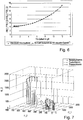
- Fig. 6 is the one from the in Fig. 5
- the individual detector signals shown according to the formula (1) determined turbidity value plotted as a function of the associated solids concentration (DM content) in g / l.
- the diamond-shaped points represent the turbidity values obtained with 100% signal yield
- the square points represent turbidity values which were determined from the individual detector signals weakened by 10%.
- the individual signals show a clearly different course at an emitter power of 100% and a signal strength reduced by 10%, this difference cannot be seen in the turbidity value determined by the four-beam alternating light method using formula (1). This is due to the relative robustness of the four-beam alternating light method with regard to minor disturbances, as already described at the beginning.
- the monitoring of the individual detector signals can therefore provide valuable additional information, and a malfunction can be detected and eliminated at an early stage, or an estimate for the further service life of a component can be carried out.
- a number n of the individual detector signals determined, in the example of the device according to Figs. 1 and 2 if this is a maximum of 8 signals, selected.
- the number n is less than or equal to the number of all detected detector signals.
- a measured value vector or a measured value point is formed from these detector signals, the components of which form the n individual detector signals.
- the measured value vector is represented in an n-dimensional vector space, the measured value point accordingly formed in an n-dimensional coordinate system. Both representations are equivalent.
- FIG. 7 An example is in Fig. 7 shown.
- three of a total of four individual detector signals of the 135 ° channel are shown in a three-dimensional coordinate system for measurements in different measuring media.
- the three detector signals shown correspond to the propagation paths 1_1, 1_2 and 2_2 of the in FIG Fig. 3 a) shown schemes.
- the measuring media are activated sludge (dots), digested sludge (circles) and press sludge (stars).
- the individual measured value points correspond to different solids concentrations.
- an area or an n-dimensional area within the n-dimensional vector space is modeled or learned using machine learning methods .
- this n-dimensional area is therefore a plane on which all measured value points lie.
- a new measured value vector or point can then be evaluated diagnostically by adding a distance of the vector or point to the estimated or learned area, in the example of Fig. 7 to the determined plane is.
- measured value outliers can be detected and, for example, the degree of contamination of individual channels can be determined.
- a probability can be determined with which the new measured value vector, and thus the last one determined turbidity value represents the actual turbidity of the measuring medium. This can be used to check the plausibility of the measured value.
- the n-dimensional volume can be modified further and further.
- the shape of the n-dimensional volume is essentially retained, but is shifted within the n-dimensional space.
- the n-dimensional volume When a component, e.g. a light-emitting diode, ages, the n-dimensional volume is shifted as well as compressed or stretched.
- the type of distortion of the n-dimensional volume can be assessed using a learning method or a model in such a way that the type of disturbance can be deduced directly from the distortion and, if necessary, suitable countermeasures such as cleaning or component replacement can be taken automatically.
- the learning memory in particular the neural network, learn different n-dimensional areas in accordance with different possible disturbances.
- a newly determined n-dimensional measured value point can then be compared with the various n-dimensional areas assigned to different disturbances, and a probability can be determined with which one of the different disturbances is present.
Landscapes
- Physics & Mathematics (AREA)
- Health & Medical Sciences (AREA)
- Life Sciences & Earth Sciences (AREA)
- Chemical & Material Sciences (AREA)
- Analytical Chemistry (AREA)
- Biochemistry (AREA)
- General Health & Medical Sciences (AREA)
- General Physics & Mathematics (AREA)
- Immunology (AREA)
- Pathology (AREA)
- Investigating Or Analysing Materials By Optical Means (AREA)
Claims (9)
- Procédé destiné à la mesure de turbidité dans un produit (18) au moyen d'un dispositif comprenantau moins un premier émetteur (E1) et un deuxième émetteur (E2) etau moins un premier détecteur (D1) et un deuxième détecteur (D2),le premier émetteur (E1) et le deuxième émetteur (E2) étant chacun successivement excités pour générer un signal lumineux dirigé dans le produit mesuré (18), et le signal lumineux respectif parcourant à chaque fois un premier chemin de propagation à travers le produit mesuré (18) jusqu'au premier détecteur (D1) et étant converti par ce dernier en un premier signal de détecteur, et parcourant à chaque fois un deuxième chemin de propagation à travers le produit mesuré (18) jusqu'au deuxième détecteur (D2) et étant converti par ce dernier en un deuxième signal de détecteur,une valeur de turbidité étant déterminée en utilisant le premier et le deuxième signal de détecteur,un troisième détecteur (D3) et un quatrième détecteur (D4) étant utilisés, auxquels le signal lumineux du premier émetteur (E1) et du deuxième émetteur (E2) parvient respectivement sur un troisième chemin de propagation à travers le produit mesuré (18) et un quatrième chemin de propagation à travers le produit mesuré (18), le troisième détecteur (D3) convertissant le signal lumineux en un troisième signal de détecteur et le quatrième détecteur (D4) convertissant le signal lumineux en un quatrième signal de détecteur, et une valeur de turbidité supplémentaire étant déterminée à partir du troisième et du quatrième signal de détecteur,la valeur de turbidité supplémentaire étant comparée à la valeur de turbidité déterminée à partir des signaux du premier détecteur (D1) et du deuxième détecteur (D2), en ce que les concentrations solides correspondant aux valeurs de turbidité sont déterminées à partir des valeurs de turbidité, et la différence entre la première et la deuxième concentration solide étant formée, et la différence des concentrations solides étant comparée à une valeur de seuil prédéfinie pour vérifier la plausibilité des valeurs de turbidité.
- Procédé selon la revendication 1, pour lequel la valeur de turbidité est déterminée selon la formule
 où 11_1 est le signal du premier détecteur (D1) lorsque le premier émetteur (E1) est excité,où 11_2 est le signal du premier détecteur (D1) lorsque le deuxième émetteur (E2) est excité,où 12_1 est le signal du deuxième détecteur (D2) lorsque le premier émetteur (E1) est excité, etoù 12_2 est le signal du deuxième détecteur (D2) lorsque le deuxième émetteur (E2) est excité.
 - Procédé selon la revendication 1, pour lequel une valeur de turbidité additionnelle est déterminée à partir du troisième et du quatrième signal de détecteur selon la formule
 où 13_1 est le signal du troisième détecteur (D3) lorsque le premier émetteur (E1) est excité,où 14_2 est le signal du quatrième détecteur (D4) lorsque le deuxième émetteur (E2) est excité,où 13_2 est le signal du troisième détecteur (D3) lorsque le deuxième émetteur (E2) est excité, etoù 14_1 est le signal du quatrième détecteur (D4) lorsque le premier émetteur (E1) est excité.
 - Procédé selon la revendication 1, pour lequel un message d'erreur est émis ou la mesure de turbidité est répétée si la différence dépasse la valeur de seuil prédéfinie.
- Procédé selon l'une des revendications 1 à 4, pour lequel au moins l'un des signaux de détecteur est comparé à une valeur de consigne.
- Procédé selon l'une des revendications 1 à 5,pour lequel un nombre de n signaux de détecteur est sélectionné parmi tous les signaux de détecteur utilisés pour déterminer une valeur de turbidité, etpour lequel les signaux de détecteur sélectionnés sont représentés comme des coordonnées d'un point de valeur mesurée dans un système de coordonnées à n dimensions, ou des composantes d'un vecteur de valeur mesurée dans un espace vectoriel à n dimensions, etpour lequel on détermine une distance du point de valeur mesurée ou du vecteur de valeur mesurée par rapport à une zone prédéfinie à n dimensions de l'espace ponctuel ou de l'espace vectoriel, qui est déterminée notamment à partir d'un modèle ou apprise au moyen d'une méthode d'apprentissage automatique.
- Procédé selon la revendication 6, pour lequel un contrôle de plausibilité, notamment un contrôle de plausibilité automatique, de la valeur de turbidité déterminée à partir des signaux de détecteur est effectué sur la base de la distance du point de valeur mesurée ou du vecteur de valeur mesurée par rapport à la zone à n dimensions prédéfinie.
- Dispositif (1) destiné à la mesure de la turbidité d'un produit (18), lequel dispositif est conçu pour la mise en œuvre d'un procédé selon au moins l'une des revendications 1 à 7, lequel dispositif comprendau moins un premier émetteur (E1, 9) et un deuxième émetteur (E2) et au moins un premier détecteur (D1, 11) et un deuxième détecteur (D2),les émetteurs (E1, E2, 9) et les détecteurs (D1, D2, 11) étant disposés les uns par rapport aux autres de telle sorte qu'un signal lumineux généré par les émetteurs (E1, E2, 9) et dirigé dans le produit mesuré (18) atteint le premier détecteur (D1, 11) respectivement sur un premier chemin de propagation à travers le produit mesuré (18) et atteint le deuxième détecteur (D2) respectivement sur un deuxième chemin de propagation à travers le produit mesuré (18),et au moins deux détecteurs supplémentaires (D3, D4, 12, 13), lesquels sont disposés de telle sorte que les signaux lumineux générés par les émetteurs (E1, E2, 9) atteignent le troisième et le quatrième détecteur sur un troisième et quatrième chemin de propagation, etune unité d'évaluation, laquelle est conçue pour déterminer une valeur de turbidité du produit mesuré à partir des signaux de détecteur de l'au moins premier détecteur (D1, 11) et de l'au moins deuxième détecteur (D2), et pour déterminer une valeur de turbidité supplémentaire du produit mesuré (18) à partir des signaux de détecteur du troisième détecteur (D1, 11) et du quatrième détecteur (D2), et pour comparer les valeurs de turbidité déterminées les unes avec les autres en déterminant des concentrations solides correspondantes à partir des valeurs de turbidité, et pour former une différence entre la première et la deuxième concentration solide, et pour comparer la différence entre les concentrations solides avec une valeur de seuil prédéfinie afin de vérifier la plausibilité des valeurs de turbidité.
- Dispositif (1) selon la revendication 8,pour lequel le premier émetteur (E1, 9) et le premier détecteur (D1, 14) sont disposés côte à côte, etpour lequel le deuxième émetteur (E2) et le deuxième détecteur (D2) sont disposés en symétrie miroir par rapport au premier émetteur (E1) et au premier détecteur (D1), et pour lequel le troisième détecteur (D3, 12) et le quatrième détecteur (D4) sont disposés de telle sorte que le deuxième émetteur (E2), le deuxième détecteur (D2) et le quatrième détecteur (D4) sont disposés en symétrie miroir par rapport au premier émetteur (E1, 9), au premier détecteur (D1, 11) et au troisième détecteur (D3, 12), etpour lequel le premier émetteur (E1, 9) est conçu pour diriger, à l'état excité, un faisceau lumineux, notamment un faisceau lumineux avec une direction de faisceau principal (HA), dans le produit mesuré (18), et la normale d'une face frontale (14) du premier détecteur (D1 , 11) étant disposée selon un premier angle par rapport à la direction du faisceau principal,la normale d'une face frontale (16) du troisième détecteur (D3, 12) étant disposée selon un deuxième angle par rapport à la direction du faisceau principal (HA), et le premier angle étant différent du deuxième angle.
Applications Claiming Priority (2)
| Application Number | Priority Date | Filing Date | Title |
|---|---|---|---|
| DE102008018592A DE102008018592A1 (de) | 2008-04-11 | 2008-04-11 | Verfahren und Vorrichtung zur Trübungsmessung |
| PCT/EP2009/054322 WO2009125003A1 (fr) | 2008-04-11 | 2009-04-09 | Procédé et dispositif de mesure de turbidité |
Publications (2)
| Publication Number | Publication Date |
|---|---|
| EP2260290A1 EP2260290A1 (fr) | 2010-12-15 |
| EP2260290B1 true EP2260290B1 (fr) | 2021-11-03 |
Family
ID=40765688
Family Applications (1)
| Application Number | Title | Priority Date | Filing Date |
|---|---|---|---|
| EP09729364.1A Active EP2260290B1 (fr) | 2008-04-11 | 2009-04-09 | Procédé et dispositif de mesure de turbidité |
Country Status (5)
| Country | Link |
|---|---|
| US (1) | US8576399B2 (fr) |
| EP (1) | EP2260290B1 (fr) |
| CN (1) | CN101999072B (fr) |
| DE (1) | DE102008018592A1 (fr) |
| WO (1) | WO2009125003A1 (fr) |
Families Citing this family (22)
| Publication number | Priority date | Publication date | Assignee | Title |
|---|---|---|---|---|
| DE102009001929A1 (de) * | 2009-03-27 | 2010-09-30 | Endress + Hauser Conducta Gesellschaft für Mess- und Regeltechnik mbH + Co. KG | Trübungsmessgerät |
| DE102009027929B4 (de) * | 2009-07-22 | 2021-05-12 | Endress+Hauser Conducta Gmbh+Co. Kg | Trübungsmessgerät und ein Verfahren zur Bestimmung einer Konzentration eines Trübstoffs |
| DE102010016060A1 (de) * | 2010-03-22 | 2011-09-22 | Negele Messtechnik Gmbh | Trübungsmessgerät |
| KR20110111865A (ko) * | 2010-04-06 | 2011-10-12 | 주식회사 엔케이 | 탁도측정용 센서모듈 |
| JP5216051B2 (ja) * | 2010-06-23 | 2013-06-19 | 株式会社日立ハイテクノロジーズ | 自動分析装置および自動分析方法 |
| JP5822534B2 (ja) * | 2011-05-13 | 2015-11-24 | 株式会社日立ハイテクノロジーズ | 自動分析装置 |
| DE102011084636B4 (de) * | 2011-10-17 | 2022-12-22 | Endress+Hauser Conducta Gmbh+Co. Kg | Verfahren zur Erkennung und/oder Bewertung geräte- und/oder prozessbedingter Störungen eines Messsignals |
| DE102012107214A1 (de) * | 2012-08-07 | 2014-02-13 | Endress + Hauser Conducta Gesellschaft für Mess- und Regeltechnik mbH + Co. KG | Verfahren zur Kalibrierung eines Sensors zur Trübungsmessung |
| CA2887630C (fr) * | 2012-10-15 | 2016-09-06 | Flsmidth A/S | Appareil filtrant a detection de turbidite, systeme et procedes associes |
| US10281383B2 (en) * | 2012-11-15 | 2019-05-07 | Solenis Technologies, L.P. | System and methods of determining liquid phase turbidity of multiphase wastewater |
| CA2913158A1 (fr) | 2013-05-21 | 2014-11-27 | Stephen P. Kasten | Systeme et appareil pour determiner et reguler la limpidite de l'eau |
| JP2014235061A (ja) * | 2013-05-31 | 2014-12-15 | 東亜ディーケーケー株式会社 | 濁度センサ |
| WO2015043675A1 (fr) | 2013-09-30 | 2015-04-02 | Hach Lange Gmbh | Turbidimètre néphélométrique et procédé de détection de la contamination d'une cuvette à échantillon d'un turbidimètre néphélométrique |
| DE102013111416A1 (de) * | 2013-10-16 | 2015-04-30 | Endress + Hauser Conducta Gesellschaft für Mess- und Regeltechnik mbH + Co. KG | Verfahren zum Bestimmen zumindest einer physikalischen, chemischen und/oder biologischen Messgröße mittels optischer Sensoren und Trübungssensoren |
| CN103575705A (zh) * | 2013-11-19 | 2014-02-12 | 苏州热工研究院有限公司 | 一种浊度仪和水的浊度的测量方法 |
| CN104181108B (zh) * | 2014-08-29 | 2016-06-15 | 山东东润仪表科技股份有限公司 | 一种带消泡器的在线式浊度传感器 |
| AU2015326540B2 (en) * | 2014-09-29 | 2020-11-26 | Bd Kiestra B.V. | Apparatus for optical inspection of small volumes of liquid sample and cuvettes therefor |
| DE102014118205B4 (de) * | 2014-12-09 | 2022-09-29 | Endress+Hauser Conducta Gmbh+Co. Kg | Verfahren zur Bestimmung einer Trübung und Trübungssensor zur Ausführung des Verfahrens |
| DE102016120785A1 (de) * | 2016-11-01 | 2018-05-03 | Krohne Messtechnik Gmbh | Verfahren und Messgerät zur Bestimmung einer Eigenschaft eines Mediums |
| DE102018125907A1 (de) * | 2018-10-18 | 2020-04-23 | Endress+Hauser Conducta Gmbh+Co. Kg | Verfahren zur Bestimmung einer Prozessgrößer mit einem Klassifikator zur Auswahl eines Modells zur Bestimmung der Prozessgröße |
| JP7056612B2 (ja) * | 2019-02-28 | 2022-04-19 | 横河電機株式会社 | 濁度測定方法及び濁度計 |
| FR3105828B1 (fr) * | 2019-12-27 | 2022-04-08 | Buerkert Werke Gmbh & Co Kg | Capteur de turbidité |
Citations (1)
| Publication number | Priority date | Publication date | Assignee | Title |
|---|---|---|---|---|
| US6331704B1 (en) * | 1998-01-20 | 2001-12-18 | Vickers, Incorporated | Hydraulic fluid contamination monitor |
Family Cites Families (14)
| Publication number | Priority date | Publication date | Assignee | Title |
|---|---|---|---|---|
| SE369229B (fr) | 1972-12-21 | 1974-08-12 | Gst Regeltechnik Gmbh | |
| US5012119A (en) * | 1989-05-19 | 1991-04-30 | Xinix, Inc. | Method and apparatus for monitoring particles using back-scattered light without interference by bubbles |
| US5140168A (en) | 1990-12-03 | 1992-08-18 | Great Lakes Instruments, Inc. | Turbidimeter signal processing circuit using alternating light sources |
| DE4142938C2 (de) | 1991-12-24 | 1995-04-20 | Staiger Mohilo & Co Gmbh | Einrichtung zum Messen von Trübungen und Feststoffkonzentrationen in Flüssigkeiten |
| DE4232957C2 (de) | 1992-05-22 | 1997-05-28 | Staiger Mohilo & Co Gmbh | Photosonde zur Messung von Trübungen und hohen Feststoffkonzentrationen in Medien |
| CH681747A5 (fr) | 1992-06-02 | 1993-05-14 | Zuellig Ag | |
| US5373367A (en) * | 1992-10-21 | 1994-12-13 | Qualimetrics, Inc. | Multiple angle and redundant visibility sensor |
| EP0707247B1 (fr) * | 1994-10-11 | 2007-02-07 | Endress + Hauser Conducta Gesellschaft für Mess- und Regeltechnik mbH + Co.KG. | Dispositif d'analyse, en particulier pour les eaux usées |
| DE19718875C1 (de) * | 1997-05-03 | 1998-10-29 | H & W Optical Instr Gmbh | Verfahren zur Bestimmung der in einem gasförmigen oder flüssigen Trägermedium enthaltenen Partikel |
| GB9924537D0 (en) * | 1999-10-18 | 1999-12-15 | Siemens Plc | Device for measuring water quality |
| DE10008517C2 (de) | 2000-02-24 | 2002-09-26 | Eppendorf Ag | Optisches Meßsystem |
| US7660678B2 (en) * | 2004-02-05 | 2010-02-09 | Medpro Holdings, Llc | On-site method of providing analysis of potency and purity of pharmaceutical compounds |
| US20060061765A1 (en) * | 2004-09-16 | 2006-03-23 | Behzad Rezvani | Turbidity sensor with improved noise rejection |
| DE102006032536B3 (de) * | 2006-07-12 | 2008-04-10 | Hochschule Für Technik Und Wirtschaft Des Saarlandes | Vorrichtung und Verfahren zur Unterscheidung von Nebelarten |
-
2008
- 2008-04-11 DE DE102008018592A patent/DE102008018592A1/de not_active Withdrawn
-
2009
- 2009-04-09 EP EP09729364.1A patent/EP2260290B1/fr active Active
- 2009-04-09 CN CN2009801128090A patent/CN101999072B/zh active Active
- 2009-04-09 WO PCT/EP2009/054322 patent/WO2009125003A1/fr not_active Ceased
- 2009-04-09 US US12/736,379 patent/US8576399B2/en active Active
Patent Citations (1)
| Publication number | Priority date | Publication date | Assignee | Title |
|---|---|---|---|---|
| US6331704B1 (en) * | 1998-01-20 | 2001-12-18 | Vickers, Incorporated | Hydraulic fluid contamination monitor |
Also Published As
| Publication number | Publication date |
|---|---|
| EP2260290A1 (fr) | 2010-12-15 |
| US20110043807A1 (en) | 2011-02-24 |
| US8576399B2 (en) | 2013-11-05 |
| WO2009125003A1 (fr) | 2009-10-15 |
| DE102008018592A1 (de) | 2009-10-15 |
| CN101999072B (zh) | 2013-08-07 |
| CN101999072A (zh) | 2011-03-30 |
Similar Documents
| Publication | Publication Date | Title |
|---|---|---|
| EP2260290B1 (fr) | Procédé et dispositif de mesure de turbidité | |
| EP0534166B1 (fr) | Procédé et dispositif pour la détermination quantitatif des substances optiquement actif | |
| EP1314006B1 (fr) | Dispositif pour determiner et/ou controler le niveau d'un materiau de remplissage dans un reservoir | |
| DE10008517C2 (de) | Optisches Meßsystem | |
| DE69526278T2 (de) | Datenauswertungsverfahren für zur Detektion von Bakterien eingesetzte Fluoreszenzsensoren | |
| EP0342647A2 (fr) | Méthode pour l'examen de matériau en feuilles | |
| EP2284518A1 (fr) | Procédé de détermination d'un paramètre, notamment du besoin en oxygène chimique (CSB), de la teneur totale en carbone organique (TOC) ou de la concentration d'un ou de plusieurs composants d'un échantillon de liquide | |
| DE2535543C3 (de) | Vorrichtung zur Feststellung von Herstellungsfehlern in einer bewegten Materialbahn | |
| DE102014118205B4 (de) | Verfahren zur Bestimmung einer Trübung und Trübungssensor zur Ausführung des Verfahrens | |
| DE2436110B2 (de) | Vorrichtung zur Feststellung von Herstellungsfehlern in einer bewegten Materialbahn | |
| DE2512640A1 (de) | Verfahren und vorrichtung zur optischen ueberpruefung von zigarettenenden | |
| DE10222797C5 (de) | Abstandsbestimmung | |
| DE102009001929A1 (de) | Trübungsmessgerät | |
| DE102014118854A1 (de) | Vorrichtung zur Bestimmung einer die Flüssigkeitsmenge repräsentierenden Größe sowie deren Verwendung | |
| DE102009027929B4 (de) | Trübungsmessgerät und ein Verfahren zur Bestimmung einer Konzentration eines Trübstoffs | |
| EP2936455A1 (fr) | Capteur et procédé de contrôle de documents de valeur | |
| EP1456819B1 (fr) | Procedes et dispositifs pour verifier l'authenticite d'articles en feuille | |
| DE102012210031A1 (de) | Vorrichtung und Verfahren zur Bewertung einer Stirnfläche eines stabförmigen Produkts der Tabak verarbeitenden Industrie | |
| DE102010062268A1 (de) | Absorptionsmesseinrichtung | |
| EP3814744B1 (fr) | Procede de determination de la distribution de la taille des particules d'un aerosol et appareil de mesure d'aerosol | |
| EP2729790A1 (fr) | Procédé pour mesurer la lumière diffusée de particules dans un milieu | |
| WO2000067547A2 (fr) | Procede de detection de serum et de determination de sa qualite, et dispositifs correspondant | |
| EP3671184A1 (fr) | Dispositif de détection d'alcool doté de canaux de mesure redondants et procédé de mesure d'une concentration en éthanol dans l'air inhalé | |
| DE102018131128A1 (de) | Optischer Sensor | |
| DE102011002080B4 (de) | Vorrichtung und Verfahren zur Bestimmung der Konzentration von Fluorophoren in einer Probe |
Legal Events
| Date | Code | Title | Description |
|---|---|---|---|
| PUAI | Public reference made under article 153(3) epc to a published international application that has entered the european phase |
Free format text: ORIGINAL CODE: 0009012 |
|
| 17P | Request for examination filed |
Effective date: 20100817 |
|
| AK | Designated contracting states |
Kind code of ref document: A1 Designated state(s): AT BE BG CH CY CZ DE DK EE ES FI FR GB GR HR HU IE IS IT LI LT LU LV MC MK MT NL NO PL PT RO SE SI SK TR |
|
| AX | Request for extension of the european patent |
Extension state: AL BA RS |
|
| RIN1 | Information on inventor provided before grant (corrected) |
Inventor name: ANDELIC, EDIN Inventor name: FRANK, RUEDIGER |
|
| DAX | Request for extension of the european patent (deleted) | ||
| RAP1 | Party data changed (applicant data changed or rights of an application transferred) |
Owner name: ENDRESS + HAUSER CONDUCTA GMBH+CO. KG |
|
| STAA | Information on the status of an ep patent application or granted ep patent |
Free format text: STATUS: EXAMINATION IS IN PROGRESS |
|
| 17Q | First examination report despatched |
Effective date: 20180502 |
|
| GRAP | Despatch of communication of intention to grant a patent |
Free format text: ORIGINAL CODE: EPIDOSNIGR1 |
|
| STAA | Information on the status of an ep patent application or granted ep patent |
Free format text: STATUS: GRANT OF PATENT IS INTENDED |
|
| INTG | Intention to grant announced |
Effective date: 20210715 |
|
| GRAS | Grant fee paid |
Free format text: ORIGINAL CODE: EPIDOSNIGR3 |
|
| GRAA | (expected) grant |
Free format text: ORIGINAL CODE: 0009210 |
|
| STAA | Information on the status of an ep patent application or granted ep patent |
Free format text: STATUS: THE PATENT HAS BEEN GRANTED |
|
| AK | Designated contracting states |
Kind code of ref document: B1 Designated state(s): AT BE BG CH CY CZ DE DK EE ES FI FR GB GR HR HU IE IS IT LI LT LU LV MC MK MT NL NO PL PT RO SE SI SK TR |
|
| REG | Reference to a national code |
Ref country code: GB Ref legal event code: FG4D Free format text: NOT ENGLISH |
|
| REG | Reference to a national code |
Ref country code: AT Ref legal event code: REF Ref document number: 1444395 Country of ref document: AT Kind code of ref document: T Effective date: 20211115 Ref country code: CH Ref legal event code: EP |
|
| REG | Reference to a national code |
Ref country code: DE Ref legal event code: R096 Ref document number: 502009016406 Country of ref document: DE |
|
| REG | Reference to a national code |
Ref country code: IE Ref legal event code: FG4D Free format text: LANGUAGE OF EP DOCUMENT: GERMAN |
|
| REG | Reference to a national code |
Ref country code: LT Ref legal event code: MG9D |
|
| PG25 | Lapsed in a contracting state [announced via postgrant information from national office to epo] |
Ref country code: LT Free format text: LAPSE BECAUSE OF FAILURE TO SUBMIT A TRANSLATION OF THE DESCRIPTION OR TO PAY THE FEE WITHIN THE PRESCRIBED TIME-LIMIT Effective date: 20211103 Ref country code: FI Free format text: LAPSE BECAUSE OF FAILURE TO SUBMIT A TRANSLATION OF THE DESCRIPTION OR TO PAY THE FEE WITHIN THE PRESCRIBED TIME-LIMIT Effective date: 20211103 Ref country code: BG Free format text: LAPSE BECAUSE OF FAILURE TO SUBMIT A TRANSLATION OF THE DESCRIPTION OR TO PAY THE FEE WITHIN THE PRESCRIBED TIME-LIMIT Effective date: 20220203 |
|
| PG25 | Lapsed in a contracting state [announced via postgrant information from national office to epo] |
Ref country code: IS Free format text: LAPSE BECAUSE OF FAILURE TO SUBMIT A TRANSLATION OF THE DESCRIPTION OR TO PAY THE FEE WITHIN THE PRESCRIBED TIME-LIMIT Effective date: 20220303 Ref country code: SE Free format text: LAPSE BECAUSE OF FAILURE TO SUBMIT A TRANSLATION OF THE DESCRIPTION OR TO PAY THE FEE WITHIN THE PRESCRIBED TIME-LIMIT Effective date: 20211103 Ref country code: PT Free format text: LAPSE BECAUSE OF FAILURE TO SUBMIT A TRANSLATION OF THE DESCRIPTION OR TO PAY THE FEE WITHIN THE PRESCRIBED TIME-LIMIT Effective date: 20220303 Ref country code: PL Free format text: LAPSE BECAUSE OF FAILURE TO SUBMIT A TRANSLATION OF THE DESCRIPTION OR TO PAY THE FEE WITHIN THE PRESCRIBED TIME-LIMIT Effective date: 20211103 Ref country code: NO Free format text: LAPSE BECAUSE OF FAILURE TO SUBMIT A TRANSLATION OF THE DESCRIPTION OR TO PAY THE FEE WITHIN THE PRESCRIBED TIME-LIMIT Effective date: 20220203 Ref country code: NL Free format text: LAPSE BECAUSE OF FAILURE TO SUBMIT A TRANSLATION OF THE DESCRIPTION OR TO PAY THE FEE WITHIN THE PRESCRIBED TIME-LIMIT Effective date: 20211103 Ref country code: LV Free format text: LAPSE BECAUSE OF FAILURE TO SUBMIT A TRANSLATION OF THE DESCRIPTION OR TO PAY THE FEE WITHIN THE PRESCRIBED TIME-LIMIT Effective date: 20211103 Ref country code: HR Free format text: LAPSE BECAUSE OF FAILURE TO SUBMIT A TRANSLATION OF THE DESCRIPTION OR TO PAY THE FEE WITHIN THE PRESCRIBED TIME-LIMIT Effective date: 20211103 Ref country code: GR Free format text: LAPSE BECAUSE OF FAILURE TO SUBMIT A TRANSLATION OF THE DESCRIPTION OR TO PAY THE FEE WITHIN THE PRESCRIBED TIME-LIMIT Effective date: 20220204 Ref country code: ES Free format text: LAPSE BECAUSE OF FAILURE TO SUBMIT A TRANSLATION OF THE DESCRIPTION OR TO PAY THE FEE WITHIN THE PRESCRIBED TIME-LIMIT Effective date: 20211103 |
|
| PG25 | Lapsed in a contracting state [announced via postgrant information from national office to epo] |
Ref country code: SK Free format text: LAPSE BECAUSE OF FAILURE TO SUBMIT A TRANSLATION OF THE DESCRIPTION OR TO PAY THE FEE WITHIN THE PRESCRIBED TIME-LIMIT Effective date: 20211103 Ref country code: RO Free format text: LAPSE BECAUSE OF FAILURE TO SUBMIT A TRANSLATION OF THE DESCRIPTION OR TO PAY THE FEE WITHIN THE PRESCRIBED TIME-LIMIT Effective date: 20211103 Ref country code: EE Free format text: LAPSE BECAUSE OF FAILURE TO SUBMIT A TRANSLATION OF THE DESCRIPTION OR TO PAY THE FEE WITHIN THE PRESCRIBED TIME-LIMIT Effective date: 20211103 Ref country code: DK Free format text: LAPSE BECAUSE OF FAILURE TO SUBMIT A TRANSLATION OF THE DESCRIPTION OR TO PAY THE FEE WITHIN THE PRESCRIBED TIME-LIMIT Effective date: 20211103 Ref country code: CZ Free format text: LAPSE BECAUSE OF FAILURE TO SUBMIT A TRANSLATION OF THE DESCRIPTION OR TO PAY THE FEE WITHIN THE PRESCRIBED TIME-LIMIT Effective date: 20211103 |
|
| REG | Reference to a national code |
Ref country code: DE Ref legal event code: R097 Ref document number: 502009016406 Country of ref document: DE |
|
| PLBE | No opposition filed within time limit |
Free format text: ORIGINAL CODE: 0009261 |
|
| STAA | Information on the status of an ep patent application or granted ep patent |
Free format text: STATUS: NO OPPOSITION FILED WITHIN TIME LIMIT |
|
| 26N | No opposition filed |
Effective date: 20220804 |
|
| PG25 | Lapsed in a contracting state [announced via postgrant information from national office to epo] |
Ref country code: SI Free format text: LAPSE BECAUSE OF FAILURE TO SUBMIT A TRANSLATION OF THE DESCRIPTION OR TO PAY THE FEE WITHIN THE PRESCRIBED TIME-LIMIT Effective date: 20211103 |
|
| REG | Reference to a national code |
Ref country code: CH Ref legal event code: PL |
|
| GBPC | Gb: european patent ceased through non-payment of renewal fee |
Effective date: 20220409 |
|
| REG | Reference to a national code |
Ref country code: BE Ref legal event code: MM Effective date: 20220430 |
|
| PG25 | Lapsed in a contracting state [announced via postgrant information from national office to epo] |
Ref country code: MC Free format text: LAPSE BECAUSE OF FAILURE TO SUBMIT A TRANSLATION OF THE DESCRIPTION OR TO PAY THE FEE WITHIN THE PRESCRIBED TIME-LIMIT Effective date: 20211103 Ref country code: LU Free format text: LAPSE BECAUSE OF NON-PAYMENT OF DUE FEES Effective date: 20220409 Ref country code: LI Free format text: LAPSE BECAUSE OF NON-PAYMENT OF DUE FEES Effective date: 20220430 Ref country code: GB Free format text: LAPSE BECAUSE OF NON-PAYMENT OF DUE FEES Effective date: 20220409 Ref country code: FR Free format text: LAPSE BECAUSE OF NON-PAYMENT OF DUE FEES Effective date: 20220430 Ref country code: CH Free format text: LAPSE BECAUSE OF NON-PAYMENT OF DUE FEES Effective date: 20220430 |
|
| PG25 | Lapsed in a contracting state [announced via postgrant information from national office to epo] |
Ref country code: BE Free format text: LAPSE BECAUSE OF NON-PAYMENT OF DUE FEES Effective date: 20220430 |
|
| PG25 | Lapsed in a contracting state [announced via postgrant information from national office to epo] |
Ref country code: IE Free format text: LAPSE BECAUSE OF NON-PAYMENT OF DUE FEES Effective date: 20220409 |
|
| PG25 | Lapsed in a contracting state [announced via postgrant information from national office to epo] |
Ref country code: IT Free format text: LAPSE BECAUSE OF FAILURE TO SUBMIT A TRANSLATION OF THE DESCRIPTION OR TO PAY THE FEE WITHIN THE PRESCRIBED TIME-LIMIT Effective date: 20211103 |
|
| REG | Reference to a national code |
Ref country code: AT Ref legal event code: MM01 Ref document number: 1444395 Country of ref document: AT Kind code of ref document: T Effective date: 20220409 |
|
| P01 | Opt-out of the competence of the unified patent court (upc) registered |
Effective date: 20230601 |
|
| PG25 | Lapsed in a contracting state [announced via postgrant information from national office to epo] |
Ref country code: AT Free format text: LAPSE BECAUSE OF NON-PAYMENT OF DUE FEES Effective date: 20220409 |
|
| PG25 | Lapsed in a contracting state [announced via postgrant information from national office to epo] |
Ref country code: HU Free format text: LAPSE BECAUSE OF FAILURE TO SUBMIT A TRANSLATION OF THE DESCRIPTION OR TO PAY THE FEE WITHIN THE PRESCRIBED TIME-LIMIT; INVALID AB INITIO Effective date: 20090409 |
|
| PG25 | Lapsed in a contracting state [announced via postgrant information from national office to epo] |
Ref country code: MK Free format text: LAPSE BECAUSE OF FAILURE TO SUBMIT A TRANSLATION OF THE DESCRIPTION OR TO PAY THE FEE WITHIN THE PRESCRIBED TIME-LIMIT Effective date: 20211103 Ref country code: CY Free format text: LAPSE BECAUSE OF FAILURE TO SUBMIT A TRANSLATION OF THE DESCRIPTION OR TO PAY THE FEE WITHIN THE PRESCRIBED TIME-LIMIT Effective date: 20211103 |
|
| PG25 | Lapsed in a contracting state [announced via postgrant information from national office to epo] |
Ref country code: MT Free format text: LAPSE BECAUSE OF FAILURE TO SUBMIT A TRANSLATION OF THE DESCRIPTION OR TO PAY THE FEE WITHIN THE PRESCRIBED TIME-LIMIT Effective date: 20211103 |
|
| PGFP | Annual fee paid to national office [announced via postgrant information from national office to epo] |
Ref country code: DE Payment date: 20250422 Year of fee payment: 17 |
|
| PG25 | Lapsed in a contracting state [announced via postgrant information from national office to epo] |
Ref country code: TR Free format text: LAPSE BECAUSE OF FAILURE TO SUBMIT A TRANSLATION OF THE DESCRIPTION OR TO PAY THE FEE WITHIN THE PRESCRIBED TIME-LIMIT Effective date: 20211103 |