EP2268904B1 - Vorrichtung zur zuführung eines reagens in ein abgasrohr einer abgasanlage eines kraftfahrzeugs - Google Patents
Vorrichtung zur zuführung eines reagens in ein abgasrohr einer abgasanlage eines kraftfahrzeugs Download PDFInfo
- Publication number
- EP2268904B1 EP2268904B1 EP09733341A EP09733341A EP2268904B1 EP 2268904 B1 EP2268904 B1 EP 2268904B1 EP 09733341 A EP09733341 A EP 09733341A EP 09733341 A EP09733341 A EP 09733341A EP 2268904 B1 EP2268904 B1 EP 2268904B1
- Authority
- EP
- European Patent Office
- Prior art keywords
- exhaust pipe
- reagent
- exhaust
- trapping medium
- medium
- Prior art date
- Legal status (The legal status is an assumption and is not a legal conclusion. Google has not performed a legal analysis and makes no representation as to the accuracy of the status listed.)
- Not-in-force
Links
Images

Classifications
-
- F—MECHANICAL ENGINEERING; LIGHTING; HEATING; WEAPONS; BLASTING
- F01—MACHINES OR ENGINES IN GENERAL; ENGINE PLANTS IN GENERAL; STEAM ENGINES
- F01N—GAS-FLOW SILENCERS OR EXHAUST APPARATUS FOR MACHINES OR ENGINES IN GENERAL; GAS-FLOW SILENCERS OR EXHAUST APPARATUS FOR INTERNAL-COMBUSTION ENGINES
- F01N3/00—Exhaust or silencing apparatus having means for purifying, rendering innocuous, or otherwise treating exhaust
- F01N3/08—Exhaust or silencing apparatus having means for purifying, rendering innocuous, or otherwise treating exhaust for rendering innocuous
- F01N3/10—Exhaust or silencing apparatus having means for purifying, rendering innocuous, or otherwise treating exhaust for rendering innocuous by thermal or catalytic conversion of noxious components of exhaust
- F01N3/18—Exhaust or silencing apparatus having means for purifying, rendering innocuous, or otherwise treating exhaust for rendering innocuous by thermal or catalytic conversion of noxious components of exhaust characterised by methods of operation; Control
- F01N3/20—Exhaust or silencing apparatus having means for purifying, rendering innocuous, or otherwise treating exhaust for rendering innocuous by thermal or catalytic conversion of noxious components of exhaust characterised by methods of operation; Control specially adapted for catalytic conversion
- F01N3/206—Adding periodically or continuously substances to exhaust gases for promoting purification, e.g. catalytic material in liquid form, NOx reducing agents
- F01N3/2066—Selective catalytic reduction [SCR]
-
- B—PERFORMING OPERATIONS; TRANSPORTING
- B01—PHYSICAL OR CHEMICAL PROCESSES OR APPARATUS IN GENERAL
- B01F—MIXING, e.g. DISSOLVING, EMULSIFYING OR DISPERSING
- B01F23/00—Mixing according to the phases to be mixed, e.g. dispersing or emulsifying
- B01F23/10—Mixing gases with gases
- B01F23/12—Mixing gases with gases with vaporisation of a liquid
-
- B—PERFORMING OPERATIONS; TRANSPORTING
- B01—PHYSICAL OR CHEMICAL PROCESSES OR APPARATUS IN GENERAL
- B01F—MIXING, e.g. DISSOLVING, EMULSIFYING OR DISPERSING
- B01F23/00—Mixing according to the phases to be mixed, e.g. dispersing or emulsifying
- B01F23/20—Mixing gases with liquids
- B01F23/21—Mixing gases with liquids by introducing liquids into gaseous media
- B01F23/213—Mixing gases with liquids by introducing liquids into gaseous media by spraying or atomising of the liquids
- B01F23/2132—Mixing gases with liquids by introducing liquids into gaseous media by spraying or atomising of the liquids using nozzles
-
- B—PERFORMING OPERATIONS; TRANSPORTING
- B01—PHYSICAL OR CHEMICAL PROCESSES OR APPARATUS IN GENERAL
- B01F—MIXING, e.g. DISSOLVING, EMULSIFYING OR DISPERSING
- B01F25/00—Flow mixers; Mixers for falling materials, e.g. solid particles
- B01F25/20—Jet mixers, i.e. mixers using high-speed fluid streams
- B01F25/25—Mixing by jets impinging against collision plates
-
- F—MECHANICAL ENGINEERING; LIGHTING; HEATING; WEAPONS; BLASTING
- F01—MACHINES OR ENGINES IN GENERAL; ENGINE PLANTS IN GENERAL; STEAM ENGINES
- F01N—GAS-FLOW SILENCERS OR EXHAUST APPARATUS FOR MACHINES OR ENGINES IN GENERAL; GAS-FLOW SILENCERS OR EXHAUST APPARATUS FOR INTERNAL-COMBUSTION ENGINES
- F01N2240/00—Combination or association of two or more different exhaust treating devices, or of at least one such device with an auxiliary device, not covered by indexing codes F01N2230/00 or F01N2250/00, one of the devices being
- F01N2240/20—Combination or association of two or more different exhaust treating devices, or of at least one such device with an auxiliary device, not covered by indexing codes F01N2230/00 or F01N2250/00, one of the devices being a flow director or deflector
-
- F—MECHANICAL ENGINEERING; LIGHTING; HEATING; WEAPONS; BLASTING
- F01—MACHINES OR ENGINES IN GENERAL; ENGINE PLANTS IN GENERAL; STEAM ENGINES
- F01N—GAS-FLOW SILENCERS OR EXHAUST APPARATUS FOR MACHINES OR ENGINES IN GENERAL; GAS-FLOW SILENCERS OR EXHAUST APPARATUS FOR INTERNAL-COMBUSTION ENGINES
- F01N2570/00—Exhaust treating apparatus eliminating, absorbing or adsorbing specific elements or compounds
- F01N2570/14—Nitrogen oxides
-
- F—MECHANICAL ENGINEERING; LIGHTING; HEATING; WEAPONS; BLASTING
- F01—MACHINES OR ENGINES IN GENERAL; ENGINE PLANTS IN GENERAL; STEAM ENGINES
- F01N—GAS-FLOW SILENCERS OR EXHAUST APPARATUS FOR MACHINES OR ENGINES IN GENERAL; GAS-FLOW SILENCERS OR EXHAUST APPARATUS FOR INTERNAL-COMBUSTION ENGINES
- F01N2610/00—Adding substances to exhaust gases
- F01N2610/02—Adding substances to exhaust gases the substance being ammonia or urea
-
- F—MECHANICAL ENGINEERING; LIGHTING; HEATING; WEAPONS; BLASTING
- F01—MACHINES OR ENGINES IN GENERAL; ENGINE PLANTS IN GENERAL; STEAM ENGINES
- F01N—GAS-FLOW SILENCERS OR EXHAUST APPARATUS FOR MACHINES OR ENGINES IN GENERAL; GAS-FLOW SILENCERS OR EXHAUST APPARATUS FOR INTERNAL-COMBUSTION ENGINES
- F01N2610/00—Adding substances to exhaust gases
- F01N2610/10—Adding substances to exhaust gases the substance being heated, e.g. by heating tank or supply line of the added substance
- F01N2610/102—Adding substances to exhaust gases the substance being heated, e.g. by heating tank or supply line of the added substance after addition to exhaust gases, e.g. by a passively or actively heated surface in the exhaust conduit
-
- F—MECHANICAL ENGINEERING; LIGHTING; HEATING; WEAPONS; BLASTING
- F01—MACHINES OR ENGINES IN GENERAL; ENGINE PLANTS IN GENERAL; STEAM ENGINES
- F01N—GAS-FLOW SILENCERS OR EXHAUST APPARATUS FOR MACHINES OR ENGINES IN GENERAL; GAS-FLOW SILENCERS OR EXHAUST APPARATUS FOR INTERNAL-COMBUSTION ENGINES
- F01N2610/00—Adding substances to exhaust gases
- F01N2610/14—Arrangements for the supply of substances, e.g. conduits
- F01N2610/1453—Sprayers or atomisers; Arrangement thereof in the exhaust apparatus
-
- Y—GENERAL TAGGING OF NEW TECHNOLOGICAL DEVELOPMENTS; GENERAL TAGGING OF CROSS-SECTIONAL TECHNOLOGIES SPANNING OVER SEVERAL SECTIONS OF THE IPC; TECHNICAL SUBJECTS COVERED BY FORMER USPC CROSS-REFERENCE ART COLLECTIONS [XRACs] AND DIGESTS
- Y02—TECHNOLOGIES OR APPLICATIONS FOR MITIGATION OR ADAPTATION AGAINST CLIMATE CHANGE
- Y02A—TECHNOLOGIES FOR ADAPTATION TO CLIMATE CHANGE
- Y02A50/00—TECHNOLOGIES FOR ADAPTATION TO CLIMATE CHANGE in human health protection, e.g. against extreme weather
- Y02A50/20—Air quality improvement or preservation, e.g. vehicle emission control or emission reduction by using catalytic converters
-
- Y—GENERAL TAGGING OF NEW TECHNOLOGICAL DEVELOPMENTS; GENERAL TAGGING OF CROSS-SECTIONAL TECHNOLOGIES SPANNING OVER SEVERAL SECTIONS OF THE IPC; TECHNICAL SUBJECTS COVERED BY FORMER USPC CROSS-REFERENCE ART COLLECTIONS [XRACs] AND DIGESTS
- Y02—TECHNOLOGIES OR APPLICATIONS FOR MITIGATION OR ADAPTATION AGAINST CLIMATE CHANGE
- Y02T—CLIMATE CHANGE MITIGATION TECHNOLOGIES RELATED TO TRANSPORTATION
- Y02T10/00—Road transport of goods or passengers
- Y02T10/10—Internal combustion engine [ICE] based vehicles
- Y02T10/12—Improving ICE efficiencies
Definitions
- the invention relates to a device for supplying a reagent in an exhaust pipe of an exhaust system of a motor vehicle, with a supply / injection point.
- reagents are increasingly used, which are introduced into certain sections of the exhaust system, for example, fed or injected.
- urea is supplied to the sequence of the selective catalytic reaction (SCR), for example, as urea-water solution.
- SCR selective catalytic reaction
- supply points / injection points are provided in the prior art, which introduce the reagent into an exhaust pipe of the exhaust system, for example, inject.
- the injected reagents, in particular urea water solution in this case is usually not completely removed from the exhaust gas flow, but forms deposits, for example by forming large drops, at the injection point opposite the inner wall of the exhaust pipe.
- urea crystals form on evaporation.
- the crystallized urea is no longer available for the SCR reaction because it already gets stuck in the area of the injection point.
- the deposits attack the exhaust pipe chemically or accumulate to cross-section narrowing, larger deposits.
- urea products such as biuret, triuret, cyanuric acid and so on
- the object of the invention is to provide a supply / injection of reagent into an exhaust pipe of an exhaust system of a motor vehicle, which avoids the disadvantages mentioned and allows safe, störunan perenniale introduction of the reagent without having to be self-regulated or controlled. In particular, a trouble-free design is desired.
- a device for supplying a reagent into an exhaust pipe of an exhaust system of a motor vehicle with a feed / injection point.
- one of the supply / injection point in the exhaust pipe spaced opposite catching medium is provided.
- the capture medium prevents the reagent, such as a urea water solution, which impinges on the feed / injection point opposite wall of the exhaust pipe and there, without being entrained by the flow, drops or immediately evaporated and leaves precipitation.
- the catching medium is a knitwear.
- a knit here is any form of permeable substance, preferably filamentous or fibrous substance is used and wherein between the individual fibers or filaments remains an air space.
- the capture medium is flow-permeable. Due to the flow-permeable design it is achieved that the reagent is indeed kept away from the opposite wall of the exhaust pipe, but is transported out of the catching medium when it is flowed through by the exhaust gas. In particular, it can be achieved that the catching medium, for example, by arrangement spaced all around from the exhaust pipe, reaches such high temperatures that also back reactions of deposits of the type mentioned (biuret, Triuret, cyanuric et cetera) are possible.
- the knitted fabric is preferably formed from high-temperature-resistant material or has such a material. This ensures that the fabric is not affected by high exhaust gas temperatures, in particular it is ensured that it does not lead to undesirable thermal structural changes and thus to possible functional impairments.
- the material is or has a metal and / or a carbon fiber and / or a ceramic fiber.
- a metal and / or a carbon fiber and / or a ceramic fiber are known in the art and can be produced inexpensively on an industrial scale, so that the knitted fabric can be made available at low cost.
- the fabric is at least partially arranged or formed in a frame. This ensures that the fabric on long use and use does not form undesirable geometrical deformations that could adversely affect its effectiveness or the exhaust gas flow in unfavorable cases.
- the fabric is formed substantially flat. In another embodiment, the fabric is formed at least in sections trough-shaped.
- the fabric can the exhaust pipe in which it is to be introduced, in the most favorable manner to adapt, always taking into account in which way the reagent is supplied or injected, and how the position of the knitted fabric to the flow direction.
- the flow through the knitted fabric is aimed at as favorably as possible, so that the incident reagent is completely entrained by the exhaust gas flow and the exhaust gas flow in turn is not affected by an unnecessary cross-sectional constriction of the exhaust pipe.
- the catching medium is arranged obliquely to a tube longitudinal axis of the exhaust pipe.
- the catching medium is therefore inclined in the exhaust pipe in such a manner that its plane crosses the pipe longitudinal axis.
- the skew is formed in such a way that the catching medium flows against the exhaust gas flow on a catching medium underside, while the reagent occurs on a catching medium upper side and is entrained therefrom by the exhaust gas flow passing through the catching medium.
- the capture medium is arranged obliquely so that it can be underflowed by the exhaust gas flow. This ensures that the exhaust gas stream at least partially pass unhindered catching medium, namely, can underflow, which can form turbulence at very strong flow of exhaust gas in the catch medium, which in turn cause improved discharge of reagent.
- the capture medium is arranged essentially transversely to an inflow direction of the reagent, that is to say in such a way that the reagent flowing into the exhaust pipe inevitably impinges on the capture medium.
- the catching medium is arranged parallel to a pipe wall of the exhaust pipe, preferably with the interposition of a heat insulation layer.
- the catching medium is in this case provided inwardly of the pipe wall of the exhaust pipe, preferably closed on the inner diameter of the exhaust pipe fitting and provided with an opening for the feed / injection point, and preferably with the interposition of a heat insulating layer to prevent unwanted heat leakage from the fabric.
- the catching medium-at least in sections- is assigned a heater.
- the heating it is possible to heat the catching medium independently of the exhaust gas temperature so far that a reverse reaction or a discharge therein reagent or its secondary products can take place.
- the heater is or has an electric heating mat.
- Electric heating mats are inexpensive to produce and familiar and can be coupled in an advantageous manner with existing control and regulation systems and controlled by them.
- a method for supplying / injecting a reagent into an exhaust pipe of an exhaust system of a motor vehicle having a supply / injection point.
- the supply / injection of the reagent takes place in the direction of a catching medium which is spaced apart from the exhaust pipe and directed towards the feed point / injection point.
- the catching medium is a knitwear.
- a knit here is any form of permeable substance, preferably filamentous or fibrous substance is used and wherein between the individual fibers or filaments remains an air space.
Landscapes
- Chemical & Material Sciences (AREA)
- Chemical Kinetics & Catalysis (AREA)
- Engineering & Computer Science (AREA)
- Health & Medical Sciences (AREA)
- Toxicology (AREA)
- Combustion & Propulsion (AREA)
- Mechanical Engineering (AREA)
- General Engineering & Computer Science (AREA)
- Exhaust Gas After Treatment (AREA)
- Sampling And Sample Adjustment (AREA)
- Testing Of Engines (AREA)
Description
- Die Erfindung betrifft eine Vorrichtung zur Zuführung eines Reagens in ein Abgasrohr einer Abgasanlage eines Kraftfahrzeugs, mit einer Zuführstelle/Einspritzstelle.
- Im Zuge der Abgasbehandlung in Kraftfahrzeugen werden zunehmend Reagenzien eingesetzt, die in bestimmte Abschnitte der Abgasanlage eingebracht, beispielsweise zugeführt oder eingespritzt werden. Beispielsweise bei DNOX-Katalysatoren, die als Selektivkatalysatoren ausgebildet sind, wird zum Ablauf der selektiv-katalytischen Reaktion (SCR) Harnstoff beispielsweise als Harnstoffwasserlösung zugeführt. Hierzu sind im Stand der Technik Zuführstellen/Einspritzstellen vorgesehen, die das Reagens in ein Abgasrohr der Abgasanlage einbringen, beispielsweise einspritzen. Die eingespritzten Reagenzien, insbesondere Harnstoffwasserlösung, wird hierbei meist nicht vollständig von der Abgasströmung abtransportiert, sondern bildet Ablagerungen, beispielsweise durch Ausbildung großer Tropfen, an der der Einspritzstelle gegenüberliegenden Innenwand des Abgasrohrs. Beim Reduktionsmittel Harnstoffwasserlösung in 32,5-prozentiger Konzentration beispielsweise bilden sich beim Verdampfen Harnstoffkristalle. Der so auskristallisierte Harnstoff steht einerseits nicht mehr für die SCR-Reaktion zur Verfügung, da er bereits im Bereich der Einspritzstelle hängen bleibt. Weiter ist in ungünstigen Fällen beobachtet worden, dass die Ablagerungen das Abgasrohr chemisch angreifen oder sich zu querschnittsverengenden, größeren Belägen anhäufen. Bei höheren Temperaturen werden derartige Ablagerungen zu Harnstofffolgeprodukten (etwa Biuret, Triuret, Cyanursäure und so weiter) umgesetzt, die teilweise nicht mehr löslich sind, insbesondere da auch das zur Lösung benötigte Wasser im Abgasrohr fehlt. Bei sehr hohen Abgastemperaturen werden diese zwar wieder verdampft, wobei aber die Abgasrohrwandung im Regelfall nicht die zur Verdampfung benötigte hohe Temperatur von zwischen 190°C und 430°C erreicht (zur Rückreaktion oder Zersetzung ist etwa erforderlich bei Biuret eine Temperatur von 190°C bis 200°C, bei Cyanursäure 300°C bis 350°C und bei Ammeline 380°C bis 430°C, während Melamine zwischen 280°C und 430°C zersetzt werden.
- Aus der
DE 10 2005 063 081 ist es bekannt, im Abgastrakt im Bereich eines Moduls zum Dosieren eines Reduktionsmittelsvorläufers einen Oberflächenverdampfer anzuordnen. - Aufgabe der Erfindung ist es, eine Zuführung/Einspritzung von Reagens in ein Abgasrohr einer Abgasanlage eines Kraftfahrzeugs bereitzustellen, die die genannten Nachteile vermeidet und eine sichere, störunanfällige Einbringung des Reagens ermöglicht, ohne selbst geregelt oder gesteuert werden zu müssen. Insbesondere ist ein eine störunanfällige Ausführung erwünscht.
- Hierzu wird eine Vorrichtung zur Zuführung eines Reagens in ein Abgasrohr einer Abgasanlage eines Kraftfahrzeugs vorgeschlagen, mit einer Zuführstelle/Einspritzstelle. Hierbei ist ein der Zuführstelle/Einspritzstelle im Abgasrohr beabstandet gegenüberliegendes Fangmedium vorgesehen. Durch das Fangmedium wird verhindert, dass das Reagens, beispielsweise eine Harnstoffwasserlösung, auf die der Zuführstelle/Einspritzstelle gegenüberliegende Wandung des Abgasrohrs auftrifft und dort, ohne von der Strömung mitgerissen zu werden, Tropfen bildet oder sofort verdampft und Niederschläge hinterlässt. Dabei ist das Fangmedium ein Gestrick. Ein Gestrick ist hierbei jede Form von durchlässig ausgebildeter Substanz, wobei bevorzugt faden- oder faserförmige Substanz verwendet wird und wobei zwischen den einzelnen Fasern oder Fäden ein Luftraum verbleibt.
- Bevorzugt ist vorgesehen, dass das Fangmedium strömungsdurchlässig ist. Durch die strömungsdurchlässige Ausbildung wird erreicht, dass das Reagens zwar von der gegenüberliegenden Wandung des Abgasrohrs abgehalten wird, aber aus dem Fangmedium heraustransportiert wird, wenn dieses vom Abgas durchströmt wird. Insbesondere kann so erreicht werden, dass das Fangmedium, beispielsweise durch allseitig vom Abgasrohr inwändig beabstandete Anordnung, so hohe Temperaturen erreicht, dass auch Rückreaktionen von Ablagerungen der eingangs genannten Art (Biuret, Triuret, Cyanursäure et cetera) möglich sind.
- Bevorzugt ist das Gestrick aus hochtemperaturfestem Material gebildet oder weist ein solches auf. Hierdurch ist gewährleistet, dass das Gestrick nicht durch hohe Abgastemperaturen beeinträchtigt wird, insbesondere ist sichergestellt, dass es nicht zu unerwünschten thermischen Strukturveränderungen und damit zu möglichen Funktionsbeeinträchtigungen kommt.
- Bevorzugt ist das Material ein Metall und/oder eine Kohlefaser und/oder eine Keramikfaser oder weist solche auf. Derartige Materialien sind im Stand der Technik geläufig und günstig großindustriell herstellbar, so dass das Gestrick kostengünstig zur Verfügung gestellt werden kann.
- In einer bevorzugten Ausführung ist das Gestrick zumindest abschnittsweise in einem Rahmen angeordnet oder ausgebildet. Hierdurch wird erreicht, dass das Gestrick auf bei langem Einsatz und Gebrauch keine unerwünschten Geometrieverformungen ausbildet, die in ungünstigen Fällen seine Wirksamkeit oder die Abgasströmung beeinträchtigen könnten.
- In einer Ausführungsform ist das Gestrick im Wesentlichen flächig ausgebildet. In einer anderen Ausführungsform ist das Gestrick zumindest abschnittsweise muldenförmig ausgebildet. Durch solche verschiedenartigen Ausbildungen lässt sich das Gestrick dem Abgasrohr, in dem es eingebracht werden soll, in möglichst günstiger Weise anpassen, wobei stets berücksichtigt wird, in welcher Art das Reagens zugeführt oder eingespritzt wird, und wie die Lage des Gestricks zur Strömungsrichtung ist. Insbesondere wird die Durchströmung des Gestricks in möglichst günstiger Weise angestrebt, damit auftreffendes Reagens vollständig von dem Abgasstrom mitgerissen wird und der Abgasstrom seinerseits nicht durch eine unnötige Querschnittsverengung des Abgasrohrs beeinträchtigt wird.
- Bevorzugt ist das Fangmedium schräg zu einer Rohrlängsachse des Abgasrohrs angeordnet. Das Fangmedium liegt demzufolge in einer solchen Art und Weise schräg im Abgasrohr, dass sich seine Ebene mit der Rohrlängsachse kreuzt. Bevorzugt ist die Schrägung derart ausgebildet, dass das Fangmedium an einer Fangmediumunterseite von dem Abgasstrom angeströmt wird, während das Reagens auf eine Fangmediumoberseite auftritt und von dort durch den durch das Fangmedium hindurchströmenden Abgasstrom mitgerissen wird.
- Besonders bevorzugt ist das Fangmedium derart schräg angeordnet, dass es von der Abgasströmung unterströmt werden kann. Hierdurch wird erreicht, dass der Abgasstrom zumindest abschnittsweise ungehindert das Fangmedium passieren, nämlich unterströmen kann, wodurch sich bei sehr starker Abgasströmung im Bereich des Fangmediums Turbulenzen bilden können, die eine wiederum verbesserte Austragung von Reagens bewirken.
- Das Fangmedium ist im Wesentlichen quer zu einer Einströmrichtung des Reagens angeordnet, also dergestalt, dass das in das Abgasrohr einströmende Reagens zwangsläufig auf das Fangmedium auftrifft.
- In einer anderen Ausführungsform ist das Fangmedium parallel zu einer Rohrwandung des Abgasrohrs, vorzugsweise unter Zwischenschaltung einer Wärmeisolationsschicht, angeordnet. Das Fangmedium ist hierbei inwandig der Rohrwandung des Abgasrohrs vorgesehen, bevorzugt geschlossen am Innendurchmesser des Abgasrohrs anliegend und mit einer Öffnung für die Zuführstelle/Einspritzstelle versehen, und bevorzugt unter Zwischenschaltung eine Wärmeisolationsschicht, um einen unerwünschten Wärmeaustrag aus dem Gestrick zu verhindern.
- In einer weiteren Ausführungsform ist, insbesondere für den Fall nicht hinrechend hoher Abgastemperaturen, wie dies beispielsweise im häufigen Kurzstreckenverkehr vorkommt, vorgesehen, dass dem Fangmedium - zumindest abschnittsweise - eine Heizung zugeordnet ist. Mittels der Heizung ist es möglich, das Fangmedium unabhängig von der Abgastemperatur so weit aufzuheizen, dass eine Rückreaktion beziehungsweise ein Austrag darin befindlichen Reagens oder seiner Folgeprodukte erfolgen kann.
- In einer Ausführungsform ist vorgesehen, dass die Heizung eine elektrische Heizmatte ist oder aufweist. Elektrische Heizmatten sind günstig herstellbar und geläufig und können auf vorteilhafte Weise mit vorhandenen Steuer- und Regelsystemen gekoppelt und von diesen angesteuert werden.
- Weiter wird ein Verfahren vorgeschlagen zur Zuführung/Einspritzung eines Reagens in ein Abgasrohr einer Abgasanlage eines Kraftfahrzeugs, das eine Zuführstelle/Einspritzstelle aufweist. Hierbei ist vorgesehen, dass die Zuführung/Einspritzung des Reagens in Richtung auf ein der Zuführstelle/Einspritzstelle dem Abgasrohr beabstandet gegenüberliegendes Fangmedium erfolgt. Auf diese Weise wird sichergestellt, dass es nicht zu einem Niederschlag von Reagens auf der Rohrwandung des Abgasrohrs kommt, so dass sich dort keine Ablagerungen/Beläge ausbilden können. Dabei ist das Fangmedium ein Gestrick. Ein Gestrick ist hierbei jede Form von durchlässig ausgebildeter Substanz, wobei bevorzugt faden- oder faserförmige Substanz verwendet wird und wobei zwischen den einzelnen Fasern oder Fäden ein Luftraum verbleibt.
- Weitere vorteilhafte Ausführungsformen ergeben sich aus den Unteransprüchen und aus Kombinationen derselben.
- Die Erfindung wird nachfolgend anhand eines Ausführungsbeispiels näher erläutert, ohne aber hierauf beschränkt zu sein.
- Es zeigen
- Figur 1
- eine Längsschnittsdarstellung eines Abgasrohrs mit einem der Zuführstelle/Einspritzstelle gegenüberliegenden Fangmedium;
- Figur 2
- einen Querschnitt dieser Vorrichtung;
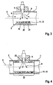
- Figur 3
- eine Ausführungsform mit am Abgasrohr parallel liegendem Fangmedium und
- Figur 4
- eine Ausführungsform mit ausgekleidetem Abgasrohr.
-
-
Figur 1 zeigt eine Längsschnittdarstellung eines Abgasrohrs 1 einer nicht näher dargestellten Abgasanlage eines Kraftfahrzeugs. Das Abgasrohr 1 weist, seine Wandung 2 oberseitig durchdringend, eine Zuführstelle/Einspritzstelle 3 auf, mit einer Einspritzdüse 4 und einem Dosierventil 5, zur Einbringung von Reagens 6, beispielsweise Harnstoffwasserlösung 7, in das Abgasrohr 1 zum Zwecke der Abgasbehandlung, insbesondere zur Durchführung einer selektiv-katalytischen Reaktion. Im Abgasrohr 1 wird Abgas 8 im Wesentlichen quer zu einer Einspritzrichtung 9 in Richtung einer Rohrlängsachse 10 geleitet. Im Wesentlichen quer zur Einspritzrichtung 9 ist, beabstandet zur Wandung 2 des Abgasrohrs 1, ein Fangmedium 11 angeordnet, das schräg zur Rohrlängsachse 10 und zur Anströmrichtung des Abgases 8 steht. Das Fangmedium 11 ist aus einem Gestrick 12 gebildet, das in einen Rahmen 13 zu seiner formstabilen Halterung innerhalb des Abgasrohrs 1 eingebracht ist. Reagens 6, das nicht vom Abgas 8 durch dessen Anströmung mitgerissen wird, trifft auf das Fangmedium 11 auf, nicht auf die Wandung 2, die der Zuführstelle/Einspritzstelle 3 diametral gegenüberliegt. Das Fangmedium 11 ist als Gestrick 12 vom Abgas 8 durchströmbar, so dass darin eintretendes Reagens 6 durch das durchströmende Abgas 8 wieder ausgetragen und mitgefördert wird. Das Fangmedium 11 ist von der Wandung 2 allseitig beabstandet, so dass es unterströmt, überströmt und endseitig beströmt werden kann. Es liegt dergestalt in dem Abgasrohr 1 ein, dass ein Auftreffen von Reagens 6 auf die Wandung 2, die der Zuführstelle/Einspritzstelle 3 genau gegenüberliegt, vermieden wird, gleichwohl aber das Abgas 8 in seiner Durchströmung des Abgasrohrs 1 möglichst wenig behindert wird. Das Gestrick 12 ist aus hochtemperaturbeständigem Material 14 ausgebildet, beispielsweise aus Metall 15 oder aus Keramikfaser 16. Auf diese Weise wird erreicht, dass das Gestrick 12 auch bei sehr hohen Temperaturen formstabil bleibt und insbesondere keine eigene (beispielsweise thermische oder chemische) Veränderung erfährt, wohingegen eingebrachtes Reagens 6 durch thermische Reaktion ausgetragen werden kann. -
Figur 2 zeigt einen Querschnitt durch das Abgasrohr 1 auf Höhe der Zuführstelle/Einspritzstelle 3 und des Fangmediums 11. Das Fangmedium 11 ist wiederum als Gestrick 12 in einer muldenförmigen Ausbildung 17 ausgebildet, die von dem Rahmen 13 stabilisiert und gehalten wird, wobei an dem Rahmen 13 Rohranschlussstücke 18 zur Fixierung des Rahmens 13 mit dem Gestrick 12 in seiner Position innerhalb des Abgasrohrs 1 angeordnet sind. Die muldenförmige Ausbildung 17 des Fangmediums 11 liegt schräg zur Anströmung durch Abgas 8, das in Längsrichtung durch das Abgasrohr 1 geführt wird, und quer zur Einspritzrichtung 9 des Reagens 6. -
Figur 3 zeigt eine andere Ausführung des Fangmediums 11 innerhalb des Abgasrohrs 1, in der das Fangmedium 11, nämlich als Gestrick 12, auf einer der Zuführstelle/Einspritzstelle 3 gegenüberliegenden Rohrseite 20 direkt an der Wandung 2 des Abgasrohrs 1 angeordnet ist, wobei zwischen dem Gestrick 12 des Fangmediums 11 und der Wandung 2 des Abgasrohrs 1 eine Wärmeisolationsschicht 19 angeordnet ist. Auch hier liegt das Fangmedium 11 quer zur Einspritzrichtung 9 des Reagens 6, jedoch nicht schräg innerhalb des Abgasrohrs 1 und allseitig beabstandet zu der Wandung 2 des Abgasrohrs 1, sondern an der gegenüberliegenden Rohrseite 20 direkt anliegend. Die Wärmeisolationsschicht 19 verhindert hierbei, dass der durch das heiße Abgas 8 erfolgende Wärmeeintrag in das Fangmedium 11, der den Wiederaustrag von Reagens 6 aus dem Gestrick 12 bewirkt, in eben dieser Wirksamkeit durch Wärmeaustrag über die Wandung 12 verringert wird. Anstelle der Wärmeisolationsschicht 19 ist hier auch eine Heizmatte 21 denkbar, insbesondere eine elektrische Heizmatte, die nur im Bedarfsfall über eine geeignete, hier nicht dargestellte Steuerelektronik zugeschaltet wird. Auf diese Weise kann durch hinreichend starke Aufheizung des Gestricks 12 ein vollständiger Wiederaustrag von darin eingebrachtem Reagens 6 oder von dessen Reaktionsprodukten erzielt werden. -
Figur 4 zeigt wiederum das Abgasrohr 1 mit einer anderen Ausführungsform des Fangmediums 11, nämlich solcher Art, dass das Fangmedium 11, als Gestrick 12, an der Wandung 2 des Abgasrohrs 1 anliegt und im Bereich der Zuführstelle/Einspritzstelle 3 eine Ausnehmung 22 zum Durchtritt des Reagens 6 aufweist. Das Abgasrohr 1 ist also in einem Abschnitt 23, in dem die Zuführung/Einspritzung von Reagens 6 erfolgt, vollständig an seiner Wandung 2 mit dem Gestrick 12 des Fangmediums 11 ausgegleitet. Lediglich im Bereich der Zuführstelle/Einspritzstelle 3 ist zum Durchtritt des Reagens 6 die Ausnehmung 22 vorgesehen. Insbesondere in Ausführungsformen, in denen ein sehr lichtgewirktes Gestrick 12 Verwendung findet und sehr heiße Abgase eingetragen werden, ist diese Ausführungsform vorteilhaft, da hier ein sicherer Wiederaustrag von eingebrachtem Reagens 6 aus dem Gestrick 12 durch das heiße Abgas bewirkt wird und der in vorstehenden Ausführungsformen gezeigte Rahmen 13 eingespart werden kann; überdies ist in der hier gezeigten Ausführungsform die Einbringung des Fangmediums 11 einfacher und damit deutlich billiger zu bewirken.
Claims (14)
- Vorrichtung zur Zuführung eines Reagens in ein Abgasrohr einer Abgasanlage eines Kraftfahrzeugs, mit einer Zuführstelle/Einspritzstelle, gekennzeichnet durch ein der Zuführstelle/Einspritzstelle (3) im Abgasrohr (1) beabstandet gegenüberliegendes Fangmedium (11), wobei das Fangmedium (11) ein Gestrick (12) ist oder ein solches aufweist.
- Vorrichtung nach Anspruch 1, dadurch gekennzeichnet, dass das Fangmedium (11) strömungsdurchlässig ist.
- Vorrichtung nach einem der vorhergehenden Ansprüche, dadurch gekennzeichnet, dass das Gestrick (12) aus hochtemperaturfestem Material (14) gebildet ist oder ein solches aufweist.
- Vorrichtung nach einem der vorhergehenden Ansprüche, dadurch gekennzeichnet, dass das Material ein Metall (15) und/oder eine Kohlefaser und/oder eine Keramikfaser (16) ist oder aufweist.
- Vorrichtung nach einem der vorhergehenden Ansprüche, dadurch gekennzeichnet, dass das Gestrick (12) zumindest abschnittsweise in einem Rahmen (13) angeordnet oder ausgebildet ist.
- Vorrichtung nach einem der vorhergehenden Ansprüche, dadurch gekennzeichnet, dass das Gestrick (12) im Wesentlichen flächig ausgebildet ist.
- Vorrichtung nach einem der vorhergehenden Ansprüche, dadurch gekennzeichnet, dass das Gestrick (12) zumindest abschnittsweise muldenförmig ausgebildet ist.
- Vorrichtung nach einem der vorhergehenden Ansprüche, dadurch gekennzeichnet, dass das Fangmedium (11) schräg zu einer Rohrlängsachse (10) des Abgasrohrs (1) angeordnet ist.
- Vorrichtung nach einem der vorhergehenden Ansprüche, dadurch gekennzeichnet, dass das Fangmedium (11) derart schräg angeordnet ist, dass es von der Abgasströmung unterströmt werden kann.
- Vorrichtung nach einem der vorhergehenden Ansprüche, dadurch gekennzeichnet, dass das Fangmedium (11) im Wesentlichen quer zu einer Einströmrichtung des Reagens (6) angeordnet ist.
- Vorrichtung nach einem der vorhergehenden Ansprüche, dadurch gekennzeichnet, dass das Fangmedium (11) parallel zu einer Rohrwandung des Abgasrohrs (1), vorzugsweise unter Zwischenschaltung einer Wärmeisolationsschicht (19), angeordnet ist.
- Vorrichtung nach einem der vorhergehenden Ansprüche, dadurch gekennzeichnet, dass dem Fangmedium (11) - zumindest abschnittsweise - eine Heizung zugeordnet ist.
- Vorrichtung nach Anspruch 12, dadurch gekennzeichnet, dass die Heizung eine elektrische Heizmatte (21) ist oder aufweist.
- Verfahren zur Zuführung/Einspritzung eines Reagens in ein Abgasrohr einer Abgasanlage eines Kraftfahrzeugs, das eine Zuführstelle/Einspritzstelle aufweist, gekennzeichnet durch die Zuführung/Einspritzung des Reagens in Richtung auf ein der Zuführstelle/Einspritzstelle im Abgasrohr beabstandet gegenüberliegendes Fangmedium, wobei das Fangmedium (11) ein Gestrick (12) ist oder ein solches aufweist.
Applications Claiming Priority (2)
| Application Number | Priority Date | Filing Date | Title |
|---|---|---|---|
| DE102008001212A DE102008001212A1 (de) | 2008-04-16 | 2008-04-16 | Vorrichtung zur Zuführung eines Reagens in ein Abgasrohr einer Abgasanlage eines Kraftfahrzeugs |
| PCT/EP2009/051223 WO2009127449A1 (de) | 2008-04-16 | 2009-02-04 | Vorrichtung zur zuführung eines reagens in ein abgasrohr einer abgasanlage eines kraftfahrzeugs |
Publications (2)
| Publication Number | Publication Date |
|---|---|
| EP2268904A1 EP2268904A1 (de) | 2011-01-05 |
| EP2268904B1 true EP2268904B1 (de) | 2011-11-09 |
Family
ID=40527590
Family Applications (1)
| Application Number | Title | Priority Date | Filing Date |
|---|---|---|---|
| EP09733341A Not-in-force EP2268904B1 (de) | 2008-04-16 | 2009-02-04 | Vorrichtung zur zuführung eines reagens in ein abgasrohr einer abgasanlage eines kraftfahrzeugs |
Country Status (4)
| Country | Link |
|---|---|
| EP (1) | EP2268904B1 (de) |
| AT (1) | ATE532953T1 (de) |
| DE (1) | DE102008001212A1 (de) |
| WO (1) | WO2009127449A1 (de) |
Cited By (2)
| Publication number | Priority date | Publication date | Assignee | Title |
|---|---|---|---|---|
| US11506099B1 (en) | 2021-08-24 | 2022-11-22 | Tenneco Automotive Operating Company Inc. | Electrically-heated mix pipe for processing diesel exhaust fluid in a selective catalytic reduction system |
| EP4130446A1 (de) * | 2021-08-05 | 2023-02-08 | Friedrich Boysen GmbH & Co. KG | Mischvorrichtung |
Families Citing this family (15)
| Publication number | Priority date | Publication date | Assignee | Title |
|---|---|---|---|---|
| DE102010025880A1 (de) | 2010-07-02 | 2012-01-05 | Emitec Gesellschaft Für Emissionstechnologie Mbh | Abgasbehandlungsvorrichtung |
| US8793978B2 (en) * | 2011-02-04 | 2014-08-05 | Caterpillar Inc. | Exhaust system having thermally conductive dosing channel |
| DE102011088569A1 (de) * | 2011-12-14 | 2013-06-20 | Robert Bosch Gmbh | Vorrichtung und Verfahren zum Verdampfen eines Fluids in einem Abgasstrang |
| DE102012209087A1 (de) | 2012-05-30 | 2013-12-05 | Robert Bosch Gmbh | Vorrichtung zum Einbringen einer Flüssigkeit in einen Abgasstrang einer Brennkraftmaschine |
| DE102014205156A1 (de) | 2014-03-19 | 2015-09-24 | Eberspächer Exhaust Technology GmbH & Co. KG | Abgasanlage |
| DE102015201193B3 (de) * | 2015-01-23 | 2016-06-30 | Continental Automotive Gmbh | Abgasreinigungskomponente zur Reinigung der Abgase einer Verbrennungskraftmaschine |
| DE102015212485B4 (de) | 2015-07-03 | 2018-06-14 | Ford Global Technologies, Llc | Abgastrakt mit gegen eine Strömungsrichtung spritzende Dosiereinrichtung, Verfahren zum Betrieb eines Abgastraktes sowie Fahrzeug mit Abgastrakt |
| EP3222834B1 (de) * | 2016-03-23 | 2019-05-08 | Volvo Car Corporation | Abgasnachbehandlungsvorrichtung für einen verbrennungsmotor |
| US10337380B2 (en) | 2017-07-07 | 2019-07-02 | Faurecia Emissions Control Technologies, Usa, Llc | Mixer for a vehicle exhaust system |
| DE102017007662A1 (de) * | 2017-08-14 | 2019-02-14 | Ruscheweyh Consult Gmbh | Abgasanlage für einen Verbrennungsmotor, Flanschblech oder Lagerhülse, Abgaskrümmer, Fahrzeug sowie Verfahren zum Betrieb einer Abgasanlage |
| GB2570312B (en) * | 2018-01-19 | 2020-04-29 | Jaguar Land Rover Ltd | Exhaust gas treatment apparatus |
| US10316721B1 (en) | 2018-04-23 | 2019-06-11 | Faurecia Emissions Control Technologies, Usa, Llc | High efficiency mixer for vehicle exhaust system |
| US10287948B1 (en) | 2018-04-23 | 2019-05-14 | Faurecia Emissions Control Technologies, Usa, Llc | High efficiency mixer for vehicle exhaust system |
| US10787946B2 (en) | 2018-09-19 | 2020-09-29 | Faurecia Emissions Control Technologies, Usa, Llc | Heated dosing mixer |
| DE102019212883A1 (de) * | 2019-08-28 | 2021-03-04 | Robert Bosch Gmbh | Mischvorrichtung |
Family Cites Families (7)
| Publication number | Priority date | Publication date | Assignee | Title |
|---|---|---|---|---|
| US7021047B2 (en) * | 2004-07-23 | 2006-04-04 | General Motors Corporation | Diesel exhaust aftertreatment device regeneration system |
| JP2007032472A (ja) * | 2005-07-28 | 2007-02-08 | Hitachi Ltd | 尿素水を用いた排気処理装置 |
| DE102005063081A1 (de) | 2005-12-29 | 2007-07-05 | Robert Bosch Gmbh | Einbauteil zur Montage in einem Abgasstrang einer Verbrennungskraftmaschine |
| JP2007321647A (ja) * | 2006-05-31 | 2007-12-13 | Hitachi Ltd | エンジン用の排気処理装置 |
| DE102006038904A1 (de) * | 2006-08-18 | 2008-02-21 | Emitec Gesellschaft Für Emissionstechnologie Mbh | Verfahren zur Zugabe mindestens eines Reaktanden zu einem Abgasstrom und Vorrichtung zur Aufbereitung eines Abgasstroms einer Verbrennungskraftmaschine |
| FR2906300B1 (fr) * | 2006-09-21 | 2011-12-16 | Renault Sas | Conduite d'echappement comportant des moyens d'injection d'un agent reducteur et des moyens de chauffage pour evaporer l'agent reducteur liquide |
| FR2906306B1 (fr) * | 2006-09-21 | 2008-12-12 | Renault Sas | Agencement pour la depollution d'un moteur thermique comportant un conduit muni d'un element en saillie |
-
2008
- 2008-04-16 DE DE102008001212A patent/DE102008001212A1/de not_active Withdrawn
-
2009
- 2009-02-04 AT AT09733341T patent/ATE532953T1/de active
- 2009-02-04 EP EP09733341A patent/EP2268904B1/de not_active Not-in-force
- 2009-02-04 WO PCT/EP2009/051223 patent/WO2009127449A1/de not_active Ceased
Cited By (3)
| Publication number | Priority date | Publication date | Assignee | Title |
|---|---|---|---|---|
| EP4130446A1 (de) * | 2021-08-05 | 2023-02-08 | Friedrich Boysen GmbH & Co. KG | Mischvorrichtung |
| US11814999B2 (en) | 2021-08-05 | 2023-11-14 | Friedrich Boysen Gmbh & Co. Kg | Mixing apparatus |
| US11506099B1 (en) | 2021-08-24 | 2022-11-22 | Tenneco Automotive Operating Company Inc. | Electrically-heated mix pipe for processing diesel exhaust fluid in a selective catalytic reduction system |
Also Published As
| Publication number | Publication date |
|---|---|
| DE102008001212A1 (de) | 2009-10-22 |
| ATE532953T1 (de) | 2011-11-15 |
| EP2268904A1 (de) | 2011-01-05 |
| WO2009127449A1 (de) | 2009-10-22 |
Similar Documents
| Publication | Publication Date | Title |
|---|---|---|
| EP2268904B1 (de) | Vorrichtung zur zuführung eines reagens in ein abgasrohr einer abgasanlage eines kraftfahrzeugs | |
| DE102007051510B4 (de) | Baugruppe zur Einbringung eines Reduktionsmittels in die Abgasleitung einer Abgasanlage einer Verbrennungskraftmaschine | |
| DE19919426C1 (de) | Ventilaufnahmevorrichtung für ein Dosierventil einer Abgasnachbehandlungsanlage | |
| EP2776687B1 (de) | Dosiermodul | |
| EP2325452B1 (de) | Vorrichtung zur Nachbehandlung von Abgasen von Brennkraftmaschinen | |
| DE102011077155B4 (de) | Abgasanlage | |
| EP1977090B1 (de) | Vorrichtung zur reduktion von stickoxiden im abgas von brennkraftmaschinen | |
| EP2588723B1 (de) | Abgasbehandlungsvorrichtung | |
| DE102010021438A1 (de) | Abgasnachbehandlungsvorrichtung | |
| DE102014206907B4 (de) | Abgasreinigungsanlage für Dieselmotoren | |
| DE102007057837A1 (de) | Vorrichtung zum Zumischen eines Reduktionsmittels in einen Abgasstrom einer Brennkraftmaschine | |
| EP1908933A1 (de) | Abgasanlage für eine Brennkraftmaschine | |
| EP1939417A1 (de) | Abgasanlage für eine Brennkraftmaschine | |
| EP3797221B1 (de) | Einrichtung zum zuführen eines chemischen reaktionsmittels in den abgasstrang einer brennkraftmaschine | |
| DE69919424T2 (de) | Zirkulierender Wirbelbettkessel mit verbesserter NOx-Reduzierung | |
| EP3500739A1 (de) | Abgasnachbehandlungseinrichtung für eine verbrennungskraftmaschine eines kraftwagens | |
| DE102010049018A1 (de) | Stutzen zum Einbringen von Reduktionsmittel | |
| DE102015016244A1 (de) | Hitzeresistente Reduktionsmitteleinspritzdüse | |
| EP1767755A2 (de) | Mittels Abgasturbolader aufgeladene Brennkraftmaschine mit einem Abgasstrang mit SCR-Katalysator(en) | |
| DE102009013260A1 (de) | Vorrichtung zur selektiven katalytischen NOx-Reduktion in sauerstoffhaltigem Abgas | |
| DE102009027713A1 (de) | Abgasnachbehandlungsvorrichtung | |
| DE102008040569A1 (de) | Abgasstrang einer Brennkraftmaschine mit einer Reduktionsmittelzuführeinrichtung und Verfahren zur Reduktionsmittelzuführung | |
| DE102006047042A1 (de) | Vorrichtung und Verfahren zum Verdampfen eines Reaktionsmittels | |
| EP3260776B1 (de) | Lanzensystem, kessel enthaltend lanzensystem und verfahren zur nox-reduktion | |
| WO2011006692A1 (de) | Antriebsaggregat |
Legal Events
| Date | Code | Title | Description |
|---|---|---|---|
| PUAI | Public reference made under article 153(3) epc to a published international application that has entered the european phase |
Free format text: ORIGINAL CODE: 0009012 |
|
| 17P | Request for examination filed |
Effective date: 20101116 |
|
| AK | Designated contracting states |
Kind code of ref document: A1 Designated state(s): AT BE BG CH CY CZ DE DK EE ES FI FR GB GR HR HU IE IS IT LI LT LU LV MC MK MT NL NO PL PT RO SE SI SK TR |
|
| AX | Request for extension of the european patent |
Extension state: AL BA RS |
|
| 17Q | First examination report despatched |
Effective date: 20110401 |
|
| DAX | Request for extension of the european patent (deleted) | ||
| GRAP | Despatch of communication of intention to grant a patent |
Free format text: ORIGINAL CODE: EPIDOSNIGR1 |
|
| GRAS | Grant fee paid |
Free format text: ORIGINAL CODE: EPIDOSNIGR3 |
|
| GRAA | (expected) grant |
Free format text: ORIGINAL CODE: 0009210 |
|
| AK | Designated contracting states |
Kind code of ref document: B1 Designated state(s): AT BE BG CH CY CZ DE DK EE ES FI FR GB GR HR HU IE IS IT LI LT LU LV MC MK MT NL NO PL PT RO SE SI SK TR |
|
| REG | Reference to a national code |
Ref country code: GB Ref legal event code: FG4D Free format text: NOT ENGLISH |
|
| REG | Reference to a national code |
Ref country code: CH Ref legal event code: EP |
|
| REG | Reference to a national code |
Ref country code: IE Ref legal event code: FG4D Free format text: LANGUAGE OF EP DOCUMENT: GERMAN |
|
| REG | Reference to a national code |
Ref country code: DE Ref legal event code: R096 Ref document number: 502009001900 Country of ref document: DE Effective date: 20111229 |
|
| REG | Reference to a national code |
Ref country code: NL Ref legal event code: VDEP Effective date: 20111109 |
|
| LTIE | Lt: invalidation of european patent or patent extension |
Effective date: 20111109 |
|
| PG25 | Lapsed in a contracting state [announced via postgrant information from national office to epo] |
Ref country code: LT Free format text: LAPSE BECAUSE OF FAILURE TO SUBMIT A TRANSLATION OF THE DESCRIPTION OR TO PAY THE FEE WITHIN THE PRESCRIBED TIME-LIMIT Effective date: 20111109 Ref country code: IS Free format text: LAPSE BECAUSE OF FAILURE TO SUBMIT A TRANSLATION OF THE DESCRIPTION OR TO PAY THE FEE WITHIN THE PRESCRIBED TIME-LIMIT Effective date: 20120309 Ref country code: NO Free format text: LAPSE BECAUSE OF FAILURE TO SUBMIT A TRANSLATION OF THE DESCRIPTION OR TO PAY THE FEE WITHIN THE PRESCRIBED TIME-LIMIT Effective date: 20120209 |
|
| PG25 | Lapsed in a contracting state [announced via postgrant information from national office to epo] |
Ref country code: PL Free format text: LAPSE BECAUSE OF FAILURE TO SUBMIT A TRANSLATION OF THE DESCRIPTION OR TO PAY THE FEE WITHIN THE PRESCRIBED TIME-LIMIT Effective date: 20111109 Ref country code: NL Free format text: LAPSE BECAUSE OF FAILURE TO SUBMIT A TRANSLATION OF THE DESCRIPTION OR TO PAY THE FEE WITHIN THE PRESCRIBED TIME-LIMIT Effective date: 20111109 Ref country code: HR Free format text: LAPSE BECAUSE OF FAILURE TO SUBMIT A TRANSLATION OF THE DESCRIPTION OR TO PAY THE FEE WITHIN THE PRESCRIBED TIME-LIMIT Effective date: 20111109 Ref country code: SE Free format text: LAPSE BECAUSE OF FAILURE TO SUBMIT A TRANSLATION OF THE DESCRIPTION OR TO PAY THE FEE WITHIN THE PRESCRIBED TIME-LIMIT Effective date: 20111109 Ref country code: PT Free format text: LAPSE BECAUSE OF FAILURE TO SUBMIT A TRANSLATION OF THE DESCRIPTION OR TO PAY THE FEE WITHIN THE PRESCRIBED TIME-LIMIT Effective date: 20120309 Ref country code: SI Free format text: LAPSE BECAUSE OF FAILURE TO SUBMIT A TRANSLATION OF THE DESCRIPTION OR TO PAY THE FEE WITHIN THE PRESCRIBED TIME-LIMIT Effective date: 20111109 Ref country code: GR Free format text: LAPSE BECAUSE OF FAILURE TO SUBMIT A TRANSLATION OF THE DESCRIPTION OR TO PAY THE FEE WITHIN THE PRESCRIBED TIME-LIMIT Effective date: 20120210 Ref country code: LV Free format text: LAPSE BECAUSE OF FAILURE TO SUBMIT A TRANSLATION OF THE DESCRIPTION OR TO PAY THE FEE WITHIN THE PRESCRIBED TIME-LIMIT Effective date: 20111109 |
|
| REG | Reference to a national code |
Ref country code: IE Ref legal event code: FD4D |
|
| PG25 | Lapsed in a contracting state [announced via postgrant information from national office to epo] |
Ref country code: CY Free format text: LAPSE BECAUSE OF FAILURE TO SUBMIT A TRANSLATION OF THE DESCRIPTION OR TO PAY THE FEE WITHIN THE PRESCRIBED TIME-LIMIT Effective date: 20111109 |
|
| PG25 | Lapsed in a contracting state [announced via postgrant information from national office to epo] |
Ref country code: CZ Free format text: LAPSE BECAUSE OF FAILURE TO SUBMIT A TRANSLATION OF THE DESCRIPTION OR TO PAY THE FEE WITHIN THE PRESCRIBED TIME-LIMIT Effective date: 20111109 Ref country code: BG Free format text: LAPSE BECAUSE OF FAILURE TO SUBMIT A TRANSLATION OF THE DESCRIPTION OR TO PAY THE FEE WITHIN THE PRESCRIBED TIME-LIMIT Effective date: 20120209 Ref country code: EE Free format text: LAPSE BECAUSE OF FAILURE TO SUBMIT A TRANSLATION OF THE DESCRIPTION OR TO PAY THE FEE WITHIN THE PRESCRIBED TIME-LIMIT Effective date: 20111109 Ref country code: DK Free format text: LAPSE BECAUSE OF FAILURE TO SUBMIT A TRANSLATION OF THE DESCRIPTION OR TO PAY THE FEE WITHIN THE PRESCRIBED TIME-LIMIT Effective date: 20111109 Ref country code: IE Free format text: LAPSE BECAUSE OF FAILURE TO SUBMIT A TRANSLATION OF THE DESCRIPTION OR TO PAY THE FEE WITHIN THE PRESCRIBED TIME-LIMIT Effective date: 20111109 Ref country code: SK Free format text: LAPSE BECAUSE OF FAILURE TO SUBMIT A TRANSLATION OF THE DESCRIPTION OR TO PAY THE FEE WITHIN THE PRESCRIBED TIME-LIMIT Effective date: 20111109 |
|
| BERE | Be: lapsed |
Owner name: ROBERT BOSCH G.M.B.H. Effective date: 20120228 |
|
| PG25 | Lapsed in a contracting state [announced via postgrant information from national office to epo] |
Ref country code: RO Free format text: LAPSE BECAUSE OF FAILURE TO SUBMIT A TRANSLATION OF THE DESCRIPTION OR TO PAY THE FEE WITHIN THE PRESCRIBED TIME-LIMIT Effective date: 20111109 Ref country code: IT Free format text: LAPSE BECAUSE OF FAILURE TO SUBMIT A TRANSLATION OF THE DESCRIPTION OR TO PAY THE FEE WITHIN THE PRESCRIBED TIME-LIMIT Effective date: 20111109 |
|
| PLBE | No opposition filed within time limit |
Free format text: ORIGINAL CODE: 0009261 |
|
| STAA | Information on the status of an ep patent application or granted ep patent |
Free format text: STATUS: NO OPPOSITION FILED WITHIN TIME LIMIT |
|
| PG25 | Lapsed in a contracting state [announced via postgrant information from national office to epo] |
Ref country code: MC Free format text: LAPSE BECAUSE OF NON-PAYMENT OF DUE FEES Effective date: 20120229 |
|
| 26N | No opposition filed |
Effective date: 20120810 |
|
| REG | Reference to a national code |
Ref country code: DE Ref legal event code: R097 Ref document number: 502009001900 Country of ref document: DE Effective date: 20120810 |
|
| PG25 | Lapsed in a contracting state [announced via postgrant information from national office to epo] |
Ref country code: BE Free format text: LAPSE BECAUSE OF NON-PAYMENT OF DUE FEES Effective date: 20120228 |
|
| PG25 | Lapsed in a contracting state [announced via postgrant information from national office to epo] |
Ref country code: MK Free format text: LAPSE BECAUSE OF FAILURE TO SUBMIT A TRANSLATION OF THE DESCRIPTION OR TO PAY THE FEE WITHIN THE PRESCRIBED TIME-LIMIT Effective date: 20111109 |
|
| PG25 | Lapsed in a contracting state [announced via postgrant information from national office to epo] |
Ref country code: ES Free format text: LAPSE BECAUSE OF FAILURE TO SUBMIT A TRANSLATION OF THE DESCRIPTION OR TO PAY THE FEE WITHIN THE PRESCRIBED TIME-LIMIT Effective date: 20120220 |
|
| PG25 | Lapsed in a contracting state [announced via postgrant information from national office to epo] |
Ref country code: FI Free format text: LAPSE BECAUSE OF FAILURE TO SUBMIT A TRANSLATION OF THE DESCRIPTION OR TO PAY THE FEE WITHIN THE PRESCRIBED TIME-LIMIT Effective date: 20111109 |
|
| PG25 | Lapsed in a contracting state [announced via postgrant information from national office to epo] |
Ref country code: MT Free format text: LAPSE BECAUSE OF FAILURE TO SUBMIT A TRANSLATION OF THE DESCRIPTION OR TO PAY THE FEE WITHIN THE PRESCRIBED TIME-LIMIT Effective date: 20111109 |
|
| REG | Reference to a national code |
Ref country code: CH Ref legal event code: PL |
|
| GBPC | Gb: european patent ceased through non-payment of renewal fee |
Effective date: 20130204 |
|
| PG25 | Lapsed in a contracting state [announced via postgrant information from national office to epo] |
Ref country code: CH Free format text: LAPSE BECAUSE OF NON-PAYMENT OF DUE FEES Effective date: 20130228 Ref country code: LI Free format text: LAPSE BECAUSE OF NON-PAYMENT OF DUE FEES Effective date: 20130228 |
|
| PG25 | Lapsed in a contracting state [announced via postgrant information from national office to epo] |
Ref country code: GB Free format text: LAPSE BECAUSE OF NON-PAYMENT OF DUE FEES Effective date: 20130204 |
|
| PG25 | Lapsed in a contracting state [announced via postgrant information from national office to epo] |
Ref country code: TR Free format text: LAPSE BECAUSE OF FAILURE TO SUBMIT A TRANSLATION OF THE DESCRIPTION OR TO PAY THE FEE WITHIN THE PRESCRIBED TIME-LIMIT Effective date: 20111109 |
|
| PG25 | Lapsed in a contracting state [announced via postgrant information from national office to epo] |
Ref country code: LU Free format text: LAPSE BECAUSE OF NON-PAYMENT OF DUE FEES Effective date: 20120204 |
|
| PG25 | Lapsed in a contracting state [announced via postgrant information from national office to epo] |
Ref country code: HU Free format text: LAPSE BECAUSE OF FAILURE TO SUBMIT A TRANSLATION OF THE DESCRIPTION OR TO PAY THE FEE WITHIN THE PRESCRIBED TIME-LIMIT Effective date: 20090204 |
|
| REG | Reference to a national code |
Ref country code: AT Ref legal event code: MM01 Ref document number: 532953 Country of ref document: AT Kind code of ref document: T Effective date: 20140204 |
|
| PG25 | Lapsed in a contracting state [announced via postgrant information from national office to epo] |
Ref country code: AT Free format text: LAPSE BECAUSE OF NON-PAYMENT OF DUE FEES Effective date: 20140204 |
|
| REG | Reference to a national code |
Ref country code: FR Ref legal event code: PLFP Year of fee payment: 8 |
|
| REG | Reference to a national code |
Ref country code: FR Ref legal event code: PLFP Year of fee payment: 9 |
|
| REG | Reference to a national code |
Ref country code: FR Ref legal event code: PLFP Year of fee payment: 10 |
|
| PGFP | Annual fee paid to national office [announced via postgrant information from national office to epo] |
Ref country code: FR Payment date: 20190221 Year of fee payment: 11 |
|
| PGFP | Annual fee paid to national office [announced via postgrant information from national office to epo] |
Ref country code: DE Payment date: 20190423 Year of fee payment: 11 |
|
| REG | Reference to a national code |
Ref country code: DE Ref legal event code: R119 Ref document number: 502009001900 Country of ref document: DE |
|
| PG25 | Lapsed in a contracting state [announced via postgrant information from national office to epo] |
Ref country code: DE Free format text: LAPSE BECAUSE OF NON-PAYMENT OF DUE FEES Effective date: 20200901 Ref country code: FR Free format text: LAPSE BECAUSE OF NON-PAYMENT OF DUE FEES Effective date: 20200229 |