EP2275628A2 - Längenveränderbarer Knaufschließzylinder - Google Patents
Längenveränderbarer Knaufschließzylinder Download PDFInfo
- Publication number
- EP2275628A2 EP2275628A2 EP10169476A EP10169476A EP2275628A2 EP 2275628 A2 EP2275628 A2 EP 2275628A2 EP 10169476 A EP10169476 A EP 10169476A EP 10169476 A EP10169476 A EP 10169476A EP 2275628 A2 EP2275628 A2 EP 2275628A2
- Authority
- EP
- European Patent Office
- Prior art keywords
- lock cylinder
- drive shaft
- closing member
- coupling
- housing
- Prior art date
- Legal status (The legal status is an assumption and is not a legal conclusion. Google has not performed a legal analysis and makes no representation as to the accuracy of the status listed.)
- Granted
Links
Images


Classifications
-
- E—FIXED CONSTRUCTIONS
- E05—LOCKS; KEYS; WINDOW OR DOOR FITTINGS; SAFES
- E05B—LOCKS; ACCESSORIES THEREFOR; HANDCUFFS
- E05B9/00—Lock casings or latch-mechanism casings ; Fastening locks or fasteners or parts thereof to the wing
- E05B9/04—Casings of cylinder locks
- E05B9/045—Modular casings for adjusting the length of cylinder locks
-
- E—FIXED CONSTRUCTIONS
- E05—LOCKS; KEYS; WINDOW OR DOOR FITTINGS; SAFES
- E05B—LOCKS; ACCESSORIES THEREFOR; HANDCUFFS
- E05B15/00—Other details of locks; Parts for engagement by bolts of fastening devices
- E05B15/04—Spring arrangements in locks
-
- E—FIXED CONSTRUCTIONS
- E05—LOCKS; KEYS; WINDOW OR DOOR FITTINGS; SAFES
- E05B—LOCKS; ACCESSORIES THEREFOR; HANDCUFFS
- E05B47/00—Operating or controlling locks or other fastening devices by electric or magnetic means
- E05B47/06—Controlling mechanically-operated bolts by electro-magnetically-operated detents
- E05B47/0611—Cylinder locks with electromagnetic control
- E05B47/0615—Cylinder locks with electromagnetic control operated by handles, e.g. by knobs
-
- E—FIXED CONSTRUCTIONS
- E05—LOCKS; KEYS; WINDOW OR DOOR FITTINGS; SAFES
- E05B—LOCKS; ACCESSORIES THEREFOR; HANDCUFFS
- E05B47/00—Operating or controlling locks or other fastening devices by electric or magnetic means
- E05B47/06—Controlling mechanically-operated bolts by electro-magnetically-operated detents
- E05B47/0611—Cylinder locks with electromagnetic control
- E05B47/0638—Cylinder locks with electromagnetic control by disconnecting the rotor
- E05B47/0642—Cylinder locks with electromagnetic control by disconnecting the rotor axially, i.e. with an axially disengaging coupling element
-
- E—FIXED CONSTRUCTIONS
- E05—LOCKS; KEYS; WINDOW OR DOOR FITTINGS; SAFES
- E05B—LOCKS; ACCESSORIES THEREFOR; HANDCUFFS
- E05B47/00—Operating or controlling locks or other fastening devices by electric or magnetic means
- E05B47/0001—Operating or controlling locks or other fastening devices by electric or magnetic means with electric actuators; Constructional features thereof
- E05B2047/0014—Constructional features of actuators or power transmissions therefor
- E05B2047/0018—Details of actuator transmissions
- E05B2047/0026—Clutches, couplings or braking arrangements
- E05B2047/0031—Clutches, couplings or braking arrangements of the elastic type
-
- E—FIXED CONSTRUCTIONS
- E05—LOCKS; KEYS; WINDOW OR DOOR FITTINGS; SAFES
- E05B—LOCKS; ACCESSORIES THEREFOR; HANDCUFFS
- E05B47/00—Operating or controlling locks or other fastening devices by electric or magnetic means
- E05B47/0001—Operating or controlling locks or other fastening devices by electric or magnetic means with electric actuators; Constructional features thereof
- E05B47/0012—Operating or controlling locks or other fastening devices by electric or magnetic means with electric actuators; Constructional features thereof with rotary electromotors
Definitions
- the invention relates to a lock cylinder with a housing main part, which rotatably supports a closing member and a drive shaft for rotating the closing member, a housing end piece, which has a bearing eye penetrated by the drive shaft and is mounted in variierbarer distance position to the closing member on the housing main body and with a mounting knob, the in variable distance position is attached to the closing member at the free end of the drive shaft.
- a lock cylinder of the type described above describes the DE 103 02 887 B4 ,
- the lock cylinder described there has on a particular door outside side a cylinder core which is locked in a known manner with Stiftzuiensen.
- the cylinder core has a keyway for inserting a key.
- the tumbler pins are sorted by inserting the appropriate key so that the cylinder core can be rotated.
- the tip of the key couples via a coupling with a closing member, which can be rotated in the coupled state of the key to open a door lock.
- the coupling forms a slide, which sits in a frontal cavity of a drive shaft.
- the drive shaft is rotatably coupled to the closing member.
- the other, free end of the drive shaft protrudes from the side opposite the cylinder core side out of the cylinder housing and carries an actuating knob.
- the actuating knob can be attached to the drive shaft at different distances to the closing member at the free end.
- the drive shaft extends through a cavity of a housing end piece, which is fastened in a variable distance position relative to the closing member on a housing main part. The axial fixing of the drive shaft via a locking ring, with which the drive shaft is connected to the housing end.
- the invention has for its object to improve the aforementioned lock cylinder.
- Claim 1 initially and essentially provides that the housing main part has an end face which has two adjacent openings. These openings may be formed as bores. These are then all around closed openings.
- One of the openings forms the bearing cavity for the drive shaft. It may be a through hole having an opening on two sides. The one opening faces the front side and the other opening points to a housing recess in which the closing member is mounted.
- the second opening surrounds a blind hole. It is a mounting cavity in which a mounting pin of the housing end piece is seated.
- the fastening pin of the housing end piece can have a multiplicity of bores extending transversely to the direction of extension of the fastening pin.
- a fastener which is in particular formed by a fastening screw to be pushed through.
- the fastener crosses while the mounting cavity and the mounting pin.
- the fastener may optionally be plugged into one of the adjacent mounting holes.
- the penetration depth of the fastening pin is defined in the mounting cavity.
- the penetration depth defines the axial distance of the housing end piece to the closing member.
- the mounting cavity can also be designed differently. It can be open at the edge.
- the axial captivation of the drive shaft to the housing is preferably via captive means that tie the drive shaft to the housing main body.
- the drive shaft may be rotated relative to the housing body but not axially displaced from the body of the housing.
- the bearing eye which is formed by the housing end piece, can preferably be moved freely in the axial direction over the drive shaft.
- the Storage of the drive shaft thus takes place in the housing main part, since the bearing cavity formed by the housing main body has a correspondingly large axial length.
- the lock cylinder according to the invention is preferably a double lock cylinder.
- the one or more parts formed drive shaft passes through two mutually aligned bearing cavities of the housing main body and bearing eye respectively the front sides of the housing main body associated end pieces and projects with its two mutually pioneering free ends of the bearing eyes of the housing end pieces out.
- On each of the free ends of the drive shaft sits an actuating knob. Both operating knobs can be mounted in awakeschliediere distance position to the closing member on the drive shaft.
- a fastening screw is preferably used, which are screwed into one of a plurality of axially successive mounting openings of the drive shaft.
- the lock cylinder is preferably an electromechanically actuable lock cylinder. He has one of an electromechanical drive can be brought into a coupling position coupling, with which the drive shaft can be brought to the closing member in a rotationally fixed state. In the uncoupled state, the drive shaft can be rotated freely relative to the closing member.
- the electromechanical drive is preferably an electric motor with a reduction gear.
- the output shaft of the reduction gear drives a control cam.
- the control cam can be an axial rotary wedge curve. The cam extends concentrically about the axis of rotation of the output shaft of the reduction gear.
- the actuating pin On the control cam is supported in the axial direction from an actuating pin, which is acted upon by means of a return spring against the control cam. Via a clutch spring, which is supported on the actuating pin, the actuating pin is coupled to a coupling body.
- This coupling body is guided in a coupling housing in the axial direction.
- the closing member forms coupling recesses corresponding to the coupling body, into which the coupling body for the purpose of non-rotatable coupling of the closing member with the drive shaft can occur.
- the lock cylinder has an inside knob and an outside knob.
- an antenna is arranged, which can accommodate wireless communication with a principal.
- This identifier may be a transponder bearing an individual identifier. It transmits this individual identification wirelessly via the antenna to a control circuit, which is preferably arranged in the inner part of the drive shaft. With this control electronics is checked whether the identity code has a locking authorization. If this is the case, the drive shaft is coupled with the clutch.
- the power supply via a battery, which is preferably arranged in the inner knob.
- an activation signal is required. This is done by pressing a button associated with the operating knob.
- a button associated with the operating knob arranged in the peripheral portion of the handle cap of the actuating knob button must be slightly displaced against the restoring force of a spring.
- Both the inside operation knob and the outside operation knob are each a carrier of a handle cap. If the button of the outside knob is pressed, the wireless contact is made with the transponder. If an optional button of the inner knob is actuated, then only the clutch is controlled in a coupled state. Basically, it is sufficient to turn the electric motor by a certain angle of rotation.
- the drive shaft consists of two rigidly coupled individual shafts.
- a drive shaft associated with the inner knob is permanently coupled to the closing member and only the drive shaft associated with the outer operating knob is actively to be coupled electromechanically to the closing member.
- the two end pieces and in particular the outer end associated with the housing end piece may be made of a hardened metal, in particular steel.
- the drive shaft may have a circumferential annular groove, in which engages the end portion of a threaded shaft of a fastening screw.
- a fastening screw with which the housing end piece is fastened to the housing main part.
- the clutch is actuated directly upon actuation of the button assigned to the inner knob. But it is also possible that the operation of the inner button also initially leads to a contact with a transponder. Only if a transponder having a locking authorization is in the vicinity of the cylinder is the clutch actuated. On the inside of the door can be provided for this purpose in the inner knob another antenna.
- the transponder can only be a passive chip. This can be arranged on a key with a cam, so that with the key and mechanical locks can be closed.
- the lock can also be actively activated by a transmitter. It is a hand transmitter that sends an individual identifier to the lock cylinder. If a lock-authorized identifier is received by the lock cylinder, then the clutch is closed. Alternatively, but also a Electric motor open the lock or turn the lock cylinder.
- the related remote control key with remote control can have several buttons. These keys can be used to operate the lock cylinder via remote control.
- the lock cylinder can also be manually operated, eg. Via a button. But it is also possible to execute the lock cylinder without a button, so that it is only remotely operable.
- an electromechanically actuated double knob lock cylinder In the lock cylinder shown in the drawings is an electromechanically actuated double knob lock cylinder. It consists of a central housing main part 1 (see. Fig. 9 ), which has two mutually aligned bearing cavities 36, in each of which a drive shaft 4, 5 inserted.
- the drive shaft is a hollow shaft.
- the two drive shafts 4, 5 are interconnected in the middle region of the housing main part.
- the housing main part 1 has an incision in which a closing member 3 for actuating a door lock is rotatably mounted about the drive shafts 4, 5.
- an electromechanically actuated clutch With an electromechanically actuated clutch, the two rigidly coupled to each other drive shafts 4, 5 are brought to the closing member 3 in a rotationally fixed connection.
- the housing main part 1 consists of a one-piece manufactured part. It has a folding symmetry related to the cutting plane in Fig. 9 , which is the median longitudinal plane.
- the storage cavity 36 has an opening 36 'which extends along a circular floor plan.
- the arranged in the profile section mounting cavity 8 has an edge 8 ', which extends along an oval.
- the rotary mounting of the drive shafts 4, 5 takes place in the two mutually aligned bearing cavities 36. There is also the axial bondage of the drive shaft 4, 5 is provided.
- the drive shaft 4 has a circumferential annular groove 27 into which the end portion 10 'of a fastening screw 10 engages.
- the housing end piece 2 has a bearing eye 37, which is penetrated by the drive shaft 4, 5.
- the housing end piece 2 thus forms the end face of the overall housing.
- the housing end piece 2 is preferably made of a hardened metal, in particular made of steel, and thus forms a Bohrschutz.
- the mounting cavity 8 In the profile section of the housing main part 1 is the mounting cavity 8. This is designed as a blind hole and is also surrounded around the same as the bearing cavity 36.
- the mounting cavity has an elongated shape.
- the fastening pin 9 has a plurality of mutually parallel, aligned transversely to the extension of the mounting pin 9 mounting holes 11.
- the above-mentioned fastening screw 10 can optionally be inserted through one of the mounting holes 11 therethrough. As a result, the distance of the housing end piece 2 relative to the closing member 3 is adjustable.
- the fastening screw 10 not only crosses the fastening pin 9, but also the fastening cavity 8.
- the lock cylinder described above can be attached to doors of different thickness in a simple manner.
- the housing main body 2 With unscrewed Betsch Trentsknäufen 6, 7, the housing main body 2 can be inserted with screwed on the end faces end pieces 2 in a door lock, which is mounted on a door.
- the axial distance of the end pieces 2 from the shooting member 3 by selecting a specific mounting hole 11, which is penetrated by the fastening screw 10, set.
- the two fastening knobs 6 are mounted from both sides and secured in the optimum distance position to the closing member 3 on the respective drive shaft 4, 5.
- the knob 6 is removed together with the plastic core of the drive shaft 4.
- the fastening screw 14 is released. The plastic core can then be removed from the drive shaft 4.
- the production of the housing main part 1 is simplified. It is a substantially cylindrical body with a cylindrical base of a typical profile lock cylinder.
- the housing main part 1 forms two facing away from each other, extending in a plane end faces. The two end faces are parallel to each other and each have adjacent circular or rounded openings.
- An opening 36 ' forms the edge of the bearing cavity 36.
- An adjacent opening 8' forms the edge of the mounting cavity 8.
- the housing main part 1 can thus be made of a correspondingly profiled strand material.
- the facing away from each other end faces are made by merely cutting to length. In the end surfaces then only the said holes 36 and 8 need to be made and the incision for receiving the closing member. 3
- the essential electronic components are arranged in the drive shaft 4, 5 or are in the outline contour of the drive shaft 4, 5, so that the lock cylinder can be inserted with remote operation knobs 6, 7 in the door opening. Only the battery 28, which is located in a battery compartment 29 of the inner knob 7, is not integrated into the drive shaft 4, 5.
- the outside door actuating knob 6 has a core 30, which consists of an insulated material, in particular plastic.
- a handle cap 25 which is tied in the axial direction by a thread 26 on the core.
- the outer wall of the outer handle cap 25 carries a plurality of actuating projections 41 which cooperate with buttons.
- the push-button action causes a control circuit 23 arranged in the drive shaft 5 on the inside of the door to send a signal to a transponder via an antenna 24 which is located in front of the head of the outside drive shaft 4. This sends an identification signal back to the antenna 24, which is evaluated by the control circuit 23.
- the antenna 24 is seated on a circuit board 40 which is fixed in front of the head of the free end of the drive shaft 4.
- the inner operating knob 7 also has a plastic core 30 with a cavity in which the free end of the drive shaft 5 is inserted.
- the battery compartment 29 is also covered here by an axially bound handle cap 25.
- a button may be provided, which can be slightly displaced. If the button is pressed, or the control circuit 23 determines a locking authorization of the transponder after actuation of the handle cap 25 of the outer knob 6, then an electric motor 21 arranged in the drive shaft 5 is energized.
- a proximity switch in particular a capacitive proximity switch can be provided.
- the electric motor 21 carries on its output shaft, a control cam 20 having an axial rotary wedge in the form of a thread-like slope edge.
- This control curve 20 formed by the slope flank is scanned by the end of an actuating pin 19 mounted in a coupling housing 33.
- the displaceable in the axial direction against a return spring 17 actuating pin 19 has a groove 32 in which a disc 31 is supported, against which the return spring 17 acts.
- the actuating pin 19 also has a second flange, on which a clutch spring 18 is supported, which acts on a coupling body 15.
- the coupling body 15 is axially displaceable relative to the actuating pin 19 and is pressed by the clutch spring 18 against the disc 31.
- the coupling body 15 has radially projecting coupling projections 15 '.
- the coupling projections 15 'of the coupling body 15 correspond to coupling recesses 16 of the closing member 3.
- the coupling recesses 16 are formed by spaces of driving webs 34. Is brought by turning the motor 21 and associated axial displacement of the actuating pin 19 of the coupling body 15 in the coupling recess 16, the two drive shafts 4, 5 rotatably connected to the closing member 3 (see. Fig. 7 ). If one of the two operating knobs 6, 7 is rotated in this state, then the closing member 3 is entrained for actuating a room door lock.
- the lock cylinder may only have an electromechanically engageable with the closing member operating knob 6. It is preferably the outer knob.
- the inner knob can also be permanently connected to the closing member.
- the double-lock cylinder has the advantage of being adapted axially in both directions to the respective conditions.
- the cylinder housing can be length adjusted on both sides. Both operating knobs can be individually varied with regard to their distance to the closing member.
Landscapes
- Physics & Mathematics (AREA)
- Electromagnetism (AREA)
- Engineering & Computer Science (AREA)
- Mechanical Engineering (AREA)
- Lock And Its Accessories (AREA)
Abstract
Description
- Die Erfindung betrifft einen Schließzylinder mit einem Gehäusehauptteil, welches ein Schließglied und eine Antriebswelle zum Drehen des Schließgliedes drehbar lagert, einem Gehäuseendstück, welches ein von der Antriebswelle durchgriffenes Lagerauge aufweist und in variierbarer Abstandslage zum Schließglied am Gehäusehauptteil befestigt ist und mit einem Befestigungsknauf, der in variierbarer Abstandslage zum Schließglied am freien Ende der Antriebswelle befestigt ist.
- Einen Schließzylinder der vorbeschriebenen Art beschreibt die
DE 103 02 887 B4 . Der dort beschriebene Schließzylinder besitzt auf einer insbesondere türaußenseitigen Seite einen Zylinderkern, der in bekannter Weise mit Stiftzuhaltungen drehgesperrt ist. Der Zylinderkern besitzt einen Schlüsselkanal zum Einstecken eines Schlüssels. Die Zuhaltungsstifte werden durch Einstecken des passenden Schlüssels derart einsortiert, dass der Zylinderkern gedreht werden kann. Die Spitze des Schlüssels kuppelt über eine Kupplung mit einem Schließglied, welches im gekuppelten Zustand vom Schlüssel zwecks Öffnen eines Türschlosses gedreht werden kann. Die Kupplung bildet einen Schieber, der in einer stirnseitigen Höhlung einer Antriebswelle sitzt. Die Antriebswelle ist drehfest mit dem Schließglied gekuppelt. Das andere, freie Ende der Antriebswelle ragt aus der dem Zylinderkern gegenüberliegenden Seite aus dem Zylindergehäuse heraus und trägt einen Betätigungsknauf. Der Betätigungsknauf kann in verschiedenen Abstandslagen zum Schließglied am freien Ende an der Antriebswelle befestigt werden. Die Antriebswelle durchragt eine Höhlung eines Gehäuseendstücks, welches in variierbarer Abstandslage gegenüber dem Schließglied an einem Gehäusehauptteil befestigt ist. Die axiale Fixierung der Antriebswelle erfolgt über einen Sicherungsring, mit dem die Antriebswelle mit dem Gehäuseendstück verbunden ist. - Der Erfindung liegt die Aufgabe zugrunde, den eingangs genannten Schließzylinder zu verbessern.
- Gelöst wird die Aufgabe durch die in den Ansprüchen angegebene Erfindung. Der Anspruch 1 sieht zunächst und im Wesentlichen vor, dass das Gehäusehauptteil eine Stirnseite aufweist, die zwei nebeneinander liegende Öffnungen aufweist. Diese Öffnungen können als Bohrungen ausgebildet sein. Es handelt sich dann um ringsum geschlossene Öffnungen. Eine der Öffnungen bildet die Lagerhöhlung für die Antriebswelle aus. Es kann sich dabei um eine Durchgangsbohrung handeln, die an zwei Seiten jeweils eine Öffnung aufweist. Die eine Öffnung weist zur Stirnseite und die andere Öffnung weist zu einem Gehäuseeinschnitt, in welchem das Schließglied gelagert ist. Die zweite Öffnung umrandet eine Sackbohrung. Es handelt sich dabei um eine Befestigungshöhlung, in welcher ein Befestigungszapfen des Gehäuseendstücks sitzt. Der Befestigungszapfen des Gehäuseendstücks kann eine Vielzahl von quer zur Erstreckungsrichtung des Befestigungszapfens verlaufende Bohrungen aufweisen. Durch diese Bohrungen kann ein Befestigungselement, welches insbesondere von einer Befestigungsschraube gebildet ist, durchgesteckt werden. Das Befestigungselement kreuzt dabei die Befestigungshöhlung und den Befestigungszapfen. Das Befestigungselement kann wahlweise in eine der nebeneinander liegenden Befestigungsbohrungen eingesteckt werden. Hierdurch wird die Eindringtiefe des Befestigungszapfens in der Befestigungshöhlung definiert. Die Eindringtiefe definiert den Axialabstand des Gehäuseendstücks zum Schließglied. Die Befestigungshöhlung kann auch anders gestaltet sein. Sie kann randseitig offen sein. Die axiale Fesselung der Antriebswelle an das Gehäuse erfolgt bevorzugt über Fesselungsmittel, die die Antriebswelle am Gehäusehauptteil fesseln. Die Antriebswelle kann gegenüber dem Gehäusehauptteil gedreht werden, aber nicht gegenüber dem Gehäusehauptteil axial verlagert werden. Das Lagerauge, welches vom Gehäuseendstück ausgebildet wird, kann bevorzugt frei in Achsrichtung über die Antriebswelle verschoben werden. Die Lagerung der Antriebswelle erfolgt somit im Gehäusehauptteil, da die vom Gehäusehauptteil ausgebildete Lagerhöhlung eine entsprechend große axiale Länge aufweist. Bei dem erfindungsgemäßen Schließzylinder handelt es sich bevorzugt um einen Doppelschließzylinder. Die ein- oder mehrteilig ausgebildete Antriebswelle durchgreift dabei zwei miteinander fluchtende Lagerhöhlungen des Gehäusehauptteiles und Lagerauge jeweils den Stirnseiten des Gehäusehauptteiles zugeordnete Endstücke und ragt mit ihren beiden voneinander wegweisenden freien Enden aus den Lageraugen der Gehäuseendstücke heraus. Auf den freien Enden der Antriebswelle sitzt jeweils ein Betätigungsknauf. Beide Betätigungsknäufe können in unterschliedlicher Abstandslage zum Schließglied an der Antriebswelle befestigt werden. Hierzu dient bevorzugt eine Befestigungsschraube, die in eine von mehreren in Axialrichtung hintereinander liegenden Befestigungsöffnungen der Antriebswelle eingeschraubt werden. Der Schließzylinder ist bevorzugt ein elektromechanisch betätigbarer Schließzylinder. Er besitzt eine von einem elektromechanischen Antrieb in eine Kupplungsstellung bringbare Kupplung, mit der die Antriebswelle mit dem Schließglied in einen drehfesten Zustand gebracht werden kann. Im entkuppelten Zustand kann die Antriebswelle frei gegenüber dem Schließglied gedreht werden. Bei dem elektromechanischen Antrieb handelt es sich bevorzugt um einen Elektromotor mit einem Untersetzungsgetriebe. Die Abtriebswelle des Untersetzungsgetriebes treibt eine Steuerkurve an. Bei der Steuerkurve kann es sich um eine axiale Drehkeilkurve handeln. Die Steuerkurve verläuft konzentrisch um die Drehachse der Abtriebswelle des Untersetzungsgetriebes. Auf der Steuerkurve stützt sich in Axialrichtung ein Betätigungsstift ab, der mittels einer Rückstellfeder gegen die Steuerkurve beaufschlagt wird. Über eine Kupplungsfeder, die sich am Betätigungsstift abstützt, ist der Betätigungsstift mit einem Kupplungskörper gekoppelt. Dieser Kupplungskörper ist in einem Kupplungsgehäuse in Achsrichtung geführt. Das Schließglied bildet zum Kupplungskörper korrespondierende Kupplungsausnehmungen aus, in die der Kupplungskörper zwecks drehfester Kupplung des Schließgliedes mit der Antriebswelle eintreten kann. Befinden sich die Kupplungsvorsprünge des Kupplungskörpers nicht in einer Fluchtstellung mit den Kupplungsausnehmungen des Schließgliedes, weil letzteres verdreht ist, so kann der Betätigungsstift trotzdem vom elektromechanischen Antrieb verlagert werden. Der Kupplungskörper wird zwar nicht in die Kupplungsstellung verlagert. Es wird aber die Kupplungsfeder gespannt. Sobald durch Drehen eines der beiden Drehknäufe die Kupplungsvorsprünge in Fluchtlage zu den Kupplungsausnehmungen gelangen, tritt der Kupplungskörper von der Kupplungsfeder getrieben in die Kupplungsausnehmung ein. Der Schließzylinder besitzt einen Innenknauf und einen Außenknauf. Im Außenknauf ist eine Antenne angeordnet, die eine drahtlose Kommunikation mit einem Identitätsträger aufnehmen kann. Bei diesem Identitätsträger kann es sich um einen Transponder handeln, der eine individuelle Kennzeichnung trägt. Er übermittelt diese individuelle Kennzeichnung drahtlos über die Antenne zu einer Steuerschaltung, die bevorzugt im inneren Teil der Antriebswelle angeordnet ist. Mit dieser Steuerungselektronik wird geprüft, ob der Identitätscode eine Schließberechtigung besitzt. Ist dies der Fall, so wird die Antriebswelle mit der Kupplung gekuppelt. Die Stromversorgung erfolgt über eine Batterie, die bevorzugt im Innenknauf angeordnet ist. Um die Steuerschaltung mit Hilfe der Antenne zu einer drahtlosen Kommunikation mit einem Transponder anzuregen, ist ein Aktivierungssignal erforderlich. Dies erfolgt durch Betätigen eines dem Betätigungsknauf zugeordneten Tasters. Um den Taster zu betätigen, muss ein im Umfangsabschnitt der Griffkappe des Betätigungsknaufs angeordneter Taster geringfügig gegen die Rückstellkraft einer Feder verlagert werden. Sowohl der Innenbetätigungsknauf als auch der Außenbetätigungsknauf ist jeweils Träger einer Griffkappe. Wird der Taster des Außenknaufes betätigt, so erfolgt die drahtlose Kontaktaufnahme mit dem Transponder. Wird ein optionaler Taster des Innenknaufes betätigt, so wird lediglich die Kupplung in einen gekuppelten Zustand gesteuert. Grundsätzlich reicht es hierzu aus, den Elektromotor um einen bestimmten Drehwinkel zu drehen. Die Kupplungsstellung bleibt für eine gewisse Zeit aufrechterhalten. Nach Ablauf dieser Zeit wird die Verbindung zwischen Schließglied und Antriebswelle wieder entkuppelt. Der Motor dreht dann zurück. Anstelle eines mechanischen Tasters kann auch ein Näherungsschalter, insbesondere ein kapazitiver Näherungsschalter vorgesehen sein. Bei der zuvor beschriebenen Variante besteht die Antriebswelle aus zwei starr miteinander gekuppelten Einzelwellen. Es ist aber auch vorgesehen, dass eine dem Innenknauf zugeordnete Antriebswelle permanent mit dem Schließglied gekuppelt ist und nur die dem Außenbetätigungsknauf zugeordnete Antriebswelle aktiv mit dem Schließglied elektromechanisch zu kuppeln ist. Die beiden Endstücke und insbesondere das dem Außenknauf zugeordnete Gehäuseendstück kann aus einem gehärteten Metall, insbesondere Stahl, bestehen. Zur Drehfesselung der Antriebswelle an das Gehäusehauptteil kann die Antriebswelle eine Umfangsringnut aufweisen, in die der Endabschnitt eines Gewindeschaftes einer Befestigungsschraube eingreift. Es handelt sich hierbei bevorzugt um die Befestigungsschraube, mit der das Gehäuseendstück am Gehäusehauptteil befestigt ist. In einer bevorzugten Variante wird bei der Betätigung des dem inneren Knauf zugeordneten Tasters direkt die Kupplung angesteuert. Es ist aber auch möglich, dass die Betätigung des inneren Tasters ebenfalls zunächst zu einer Kontaktaufnahme mit einem Transponder führt. Nur wenn sich ein eine Schließberechtigung aufweisender Transponder in der Nähe des Zylinders befindet, wird die Kupplung betätigt. Auf der Türinnenseite kann hierzu im Innenknauf eine weitere Antenne vorgesehen sein.
- Im einfachsten Fall kann der Transponder lediglich ein passiver Chip sein. Dieser kann an einem Schlüssel mit einem Schließbart angeordnet sein, so dass mit dem Schlüssel auch mechanische Schlösser geschlossen werden können. Das Schloss kann aber auch aktiv von einem Sender betätigt werden. Es handelt sich dabei um einen Handsender, der eine individuelle Kennung an den Schließzylinder sendet. Wird vom Schließzylinder eine schließberechtigte Kennung empfangen, so wird die Kupplung geschlossen. Alternativ dazu kann aber auch ein Elektromotor das Schloss öffnen bzw. den Schließzylinder drehen. Der diesbezügliche Transponderschlüssel mit Fernbedienung kann mehrere Tasten aufweisen. Über diese Tasten kann der Schließzylinder über Fernbedienung betätigt werden. Bei dieser Variante kann der Schließzylinder auch handbetätigbar sein, bspw. über einen Taster. Es ist aber auch möglich, den Schließzylinder ohne Taster auszuführen, so dass er nur fernbetätigbar ist.
- Ein Ausführungsbeispiel der Erfindung wird nachfolgend anhand beigefügter Zeichnungen erläutert. Es zeigen:
- Fig. 1
- in perspektivischer Darstellung einen Doppelknaufzylinder,
- Fig. 2
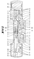
- einen Längsschnitt durch den Schließzylinder, wobei die beiden Betäti- gungsknäufe 6, 7 und die Endstücke 2 ihren minimalen Axialabstand zum Schließglied 3 einnehmen,
- Fig. 3
- einen Schnitt gemäß der Linie III - III in
Fig. 2 - Fig. 4
- eine Darstellung gemäß
Fig. 2 , wobei die beiden Betätigungsknäufe 6, 7 und die Endstücke 2 jeweils ihren maximalen axialen Abstand zum Schließglied 3 haben, - Fig. 5
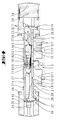
- einen Schnitt gemäß der Linie V - V in
Fig. 3 vergrößert in der entkup- pelten Stellung, - Fig. 6
- eine Darstellung gemäß
Fig. 5 , wobei der Betätigungsstift 19 in die Kupplungsstellung verlagert ist, nicht jedoch der Kupplungskörper 15, da das Schließglied 3 verdreht ist, - Fig. 7
- eine Darstellung gemäß
Fig. 6 in der Kupplungsstellung, - Fig. 8
- eine perspektivische vergrößerte Schnittdarstellung mit weggelassenen Betätigungsknäufen und
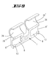
- Fig. 9
- eine perspektivische Darstellung des geschnittenen Gehäusehauptteiles 1.
- Bei dem in den Zeichnungen dargestellten Schließzylinder handelt es sich um einen elektromechanisch betätigbaren Doppelknaufschließzylinder. Er besteht aus einem zentralen Gehäusehauptteil 1 (vgl.
Fig. 9 ), welches zwei miteinander fluchtende Lagerhöhlungen 36 aufweist, in denen jeweils eine Antriebswelle 4, 5 steckt. Die Antriebswelle ist eine Hohlwelle. Die beiden Antriebswellen 4, 5 sind im mittleren Bereich des Gehäusehauptteiles miteinander verbunden. Dort besitzt das Gehäusehauptteil 1 einen Einschnitt, in dem ein Schließglied 3 zur Betätigung eines Türschlosses drehbar um die Antriebswellen 4, 5 gelagert ist. Mit einer elektromechanisch betätigbaren Kupplung können die beiden starr aneinander gekoppelten Antriebswellen 4, 5 mit dem Schließglied 3 in eine drehfeste Verbindung gebracht werden. - Das Gehäusehauptteil 1 besteht aus einem einstückig gefertigten Teil. Es besitzt eine Klappsymmetrie bezogen auf die Schnittebene in
Fig. 9 , bei der es sich um die Längsmittelebene handelt. Die Lagerhöhlung 36 hat eine Öffnung 36', die entlang eines kreisförmigen Grundrisses verläuft. Die im Profilabschnitt angeordnete Befestigungshöhlung 8 besitzt einen Rand 8', der entlang eines Ovals verläuft. - Auf den beiden freien Enden der Antriebswellen 4, 5, die voneinander wegweisend aus dem Gehäusehauptteil 1 herausragen, sitzt jeweils ein Betätigungsknauf 6, 7. Die freien Enden der Antriebswellen 4, 5 besitzen in Achsrichtung um 5 mm voneinander beabstandete Einschrauböffnungen 22. Eine Befestigungsschraube 14, die in eine Befestigungsschraubenöffnung 39 des Kernes 30 des Betätigungsknaufes 6, 7 eingesteckt ist, kann wahlweise in eine der Einschrauböffnungen 22 eingeschraubt werden. Hierdurch ist der axiale Abstand eines jeden Betätigungsknaufes 6, 7 zum Schließglied 3 einstellbar (vgl.
Fig. 2 und4 ). - Die Drehlagerung der Antriebswellen 4, 5 erfolgt in den beiden zueinander fluchtenden Lagerhöhlungen 36. Dort ist auch die axiale Fesselung der Antriebswelle 4, 5 vorgesehen. Zur axialen Fesselung besitzt die Antriebswelle 4 eine Umfangsringnut 27, in die der Endabschnitt 10' einer Befestigungsschraube 10 eingreift.
- Mit der Befestigungsschraube 10 ist ein Gehäuseendstück 2 am Gehäusehauptteil 1 in variierbarer Abstandslage zum Schließglied 3 befestigbar. Das Gehäuseendstück 2 besitzt ein Lagerauge 37, welches von der Antriebswelle 4, 5 durchgriffen ist. Das Gehäuseendstück 2 bildet somit die Stirnfläche des Gesamtgehäuses aus. Das Gehäuseendstück 2 ist bevorzugt aus einem gehärteten Metall, insbesondere aus Stahl, gefertigt und bildet somit einen Bohrschutz aus. Im Profilabschnitt des Gehäusehauptteiles 1 befindet sich die Befestigungshöhlung 8. Diese ist als Sackbohrung ausgebildet und ist ebenso ringsumschlossen wie die Lagerhöhlung 36. Die Befestigungshöhlung besitzt eine längliche Gestalt. In dieser Befestigungshöhlung 8 steckt ein Befestigungszapfen 9 des Gehäuseendstücks 2. Der Befestigungszapfen 9 besitzt mehrere parallel zueinander verlaufende, quer zur Erstreckung des Befestigungszapfens 9 ausgerichtete Befestigungsbohrungen 11. Die oben bereits erwähnte Befestigungsschraube 10 kann wahlweise durch eine der Befestigungsbohrungen 11 hindurch gesteckt werden. Hierdurch ist der Abstand des Gehäuseendstückes 2 gegenüber dem Schließglied 3 einstellbar. Die Befestigungsschraube 10 kreuzt nicht nur den Befestigungszapfen 9, sondern auch die Befestigungshöhlung 8.
- Der zuvor beschriebene Schließzylinder ist in einfacher Weise an Türen unterschiedlicher Dicke befestigbar. Mit abgeschraubten Betätigungsknäufen 6, 7 kann das Gehäusehauptteil 2 mit an den Stirnseiten angeschraubten Endstücken 2 in ein Zimmertürschloss, welches an einer Tür montiert ist, eingesteckt werden. Zuvor wurde der Axialabstand der Endstücke 2 vom Schießglied 3 durch Wahl einer bestimmten Befestigungsbohrung 11, welche von der Befestigungsschraube 10 durchgriffen ist, eingestellt. Nach dem Einsetzen des Schließzylinders in die Öffnung des Türblattes werden von beiden Seiten die beiden Befestigungsknäufe 6 montiert und in der optimalen Abstandsstellung zum Schließglied 3 an der jeweiligen Antriebswelle 4, 5 befestigt. Zur Montage genügt es, dass nur ein Knauf 6 abgenommen wird. Dabei wird der Knauf 6 zusammen mit dem Kunststoffkern von der Antriebswelle 4 entfernt. Nach Entfernen der Griffkappe wird die Befestigungsschraube 14 gelöst. Der Kunststoffkern kann dann von der Antriebswelle 4 abgezogen werden.
- Zufolge der erfindungsgemäßen Ausgestaltung ist die Fertigung des Gehäusehauptteiles 1 vereinfacht. Es handelt sich um einen im Wesentlichen zylindrischen Körper mit einer zylindrischen Grundfläche eines typischen Profilschließzylinders. Das Gehäusehauptteil 1 bildet zwei voneinander wegweisende, in einer Ebene verlaufende Stirnflächen aus. Die beiden Stirnflächen verlaufen parallel zueinander und besitzen jeweils nebeneinander liegende kreisförmige bzw. gerundete Öffnungen. Eine Öffnung 36' bildet den Rand der Lagerhöhlung 36. Eine daneben liegende Öffnung 8' bildet den Rand der Befestigungshöhlung 8. Das Gehäusehauptteil 1 kann somit aus einem entsprechend profilierten Strangmaterial gefertigt werden. Die voneinander wegweisenden Stirnflächen werden durch ledigliches Ablängen gefertigt. In die Stirnflächen brauchen sodann nur die besagten Bohrungen 36 und 8 gefertigt zu werden sowie der Einschnitt zur Aufnahme des Schließgliedes 3.
- Die wesentlichen elektronischen Komponenten sind in der Antriebswelle 4, 5 angeordnet bzw. liegen in der Umrisskontur der Antriebswelle 4, 5, so dass der Schließzylinder mit entfernten Betätigungsknäufen 6, 7 in die Türöffnung eingeschoben werden kann. Lediglich die Batterie 28, die in einem Batteriefach 29 des Innenknaufes 7 liegt, ist nicht in die Antriebswelle 4, 5 integriert.
- Der türaußenseitige Betätigungsknauf 6 besitzt einen Kern 30, der aus einem isolierten Werkstoff, insbesondere Kunststoff, besteht. Auf dem Kern steckt eine Griffkappe 25, die in Achsrichtung durch ein Gewinde 26 am Kern gefesselt ist. Die Außenwandung der äußeren Griffkappe 25 trägt mehrere Betätigungsvorsprünge 41, die mit Tastern zusammenwirken. Die Tasterbetätigung führt dazu, dass eine in der Antriebswelle 5 auf der Türinnenseite angeordnete Steuerschaltung 23 über eine Antenne 24, die vor Kopf der außenseitigen Antriebswelle 4 liegt, ein Signal an einen Transponder sendet. Dieser sendet ein Identifizierungssignal an die Antenne 24 zurück, welches von der Steuerschaltung 23 ausgewertet wird. Die Antenne 24 sitzt auf einer Platine 40, die vor Kopf des freien Endes der Antriebswelle 4 befestigt ist.
- Der innere Betätigungsknauf 7 besitzt ebenfalls einen Kunststoffkern 30 mit einer Höhlung, in welcher das freie Ende der Antriebswelle 5 steckt. Das Batteriefach 29 wird hier ebenfalls von einer axial gefesselten Griffkappe 25 überfangen. Auch hier kann ein Taster vorgesehen sein, der geringfügig verlagert werden kann. Wird der Taster betätigt, oder stellt die Steuerschaltung 23 nach Betätigung der Griffkappe 25 des Außenknaufes 6 eine Schließberechtigung des Transponders fest, so wird ein in der Antriebswelle 5 angeordneter Elektromotor 21 bestromt.
- Anstelle der zuvor beschriebenen Taster kann auch ein Näherungsschalter, insbesondere ein kapazitiver Näherungsschalter vorgesehen sein.
- Der Elektromotor 21 trägt auf seiner Abtriebswelle eine Steuerkurve 20, die einen axialen Drehkeil in Form einer gewindegangähnlichen Steigungsflanke aufweist. Diese von der Steigungsflanke ausgebildete Steuerkurve 20 wird vom Ende eines in einem Kupplungsgehäuse 33 gelagerten Betätigungsstifts 19 abgetastet. Der in Achsrichtung gegen eine Rückstellfeder 17 verlagerbare Betätigungsstift 19 besitzt eine Nut 32, in der sich eine Scheibe 31 abstützt, gegen welche die Rückstellfeder 17 wirkt.
- Der Betätigungsstift 19 besitzt darüber hinaus einen zweiten Flansch, an dem sich eine Kupplungsfeder 18 abstützt, die einen Kupplungskörper 15 beaufschlagt. Der Kupplungskörper 15 ist axial gegenüber dem Betätigungsstift 19 verlagerbar und wird von der Kupplungsfeder 18 gegen die Scheibe 31 gepresst.
- Der Kupplungskörper 15 besitzt radial ausragende Kupplungsvorsprünge 15'. Die Kupplungsvorsprünge 15' des Kupplungskörpers 15 korrespondieren mit Kupplungsausnehmungen 16 des Schließgliedes 3. Die Kupplungsausnehmungen 16 werden von Zwischenräumen von Mitnahmestegen 34 ausgebildet. Wird durch Drehen des Motors 21 und damit einhergehender Axialverlagerung des Betätigungsstiftes 19 der Kupplungskörper 15 in die Kupplungsausnehmung 16 gebracht, so sind die beiden Antriebswellen 4, 5 drehfest mit dem Schließglied 3 verbunden (vgl.
Fig. 7 ). Wird in diesem Zustand einer der beiden Betätigungsknäufe 6, 7 gedreht, so wird das Schließglied 3 zum Betätigen eines Zimmertürschlosses mitgeschleppt. - Ist hingegen der Betätigungsstift 19 in einer rückverlagerten Stellung, so ist der Kupplungskörper 15 außer Eingriff mit den Mitnahmestegen 34 (vgl.
Fig. 5 ). Wird in diesem Zustand einer der Betätigungsknäufe 6, 7 gedreht, so wird das Schließglied nicht mitgedreht. Befindet sich bei einer Verlagerung des Betätigungsstiftes 19 in die Kupplungsstellung der Kupplungskörper 15 nicht in einer Fluchtlage zur Kupplungsausnehmung 16, wird der Kupplungskörper 15 nicht mitverlagert, aber die Kupplungsfeder 18 gespannt (vgl.Fig. 6 ). Wird in diesem Zustand einer der Bewegungsknäufe 6, 7 gedreht, so erfolgt eine Relativdrehung des Kupplungskörpers 15 gegenüber dem Mitnahmesteg 34 bis die Kupplungsvorsprünge des Kupplungskörpers mit den Kupplungsausnehmungen 16 fluchten. Die sich entspannende Kupplungsfeder 18 verlagert dann den Kupplungskörper 15 in die Kupplungsstellung (vgl.Fig. 7 ). - In nicht dargestellten Varianten kann der Schließzylinder lediglich einen mit dem Schließglied elektromechanisch kuppelbaren Betätigungsknauf 6 aufweisen. Es handelt sich dabei bevorzugt um den Außenknauf. Der Innenknauf kann auch permanent mit dem Schließglied drehverbunden sein.
- Anstelle eines Elektromotors kann auch ein Magnetantrieb vorgesehen sein. Der Motor wird aber bevorzugt.
- Der Doppelschließzylinder besitzt den Vorteil, in beiden Richtungen an die jeweiligen Gegebenheiten axial angepasst zu werden. Das Zylindergehäuse kann beidseitig längeneingestellt werden. Beide Betätigungsknäufe können individuell hinsichtlich ihrer Abstandslage zum Schließglied variiert werden.
- Alle offenbarten Merkmale sind (für sich) erfindungswesentlich. In die Offenbarung der Anmeldung wird hiermit auch der Offenbarungsinhalt der zugehörigen/beigefügten Prioritätsunterlagen (Abschrift der Voranmeldung) vollinhaltlich mit einbezogen, auch zu dem Zweck, Merkmale dieser Unterlagen in Ansprüche vorliegender Anmeldung mit aufzunehmen. Die Unteransprüche charakterisieren in ihrer fakultativ nebengeordneten Fassung eigenständige erfinderische Weiterbildung des Standes der Technik, insbesondere um auf Basis dieser Ansprüche Teilanmeldungen vorzunehmen.
Claims (15)
- Schließzylinder mit einem Gehäusehauptteil (1), welches ein Schließglied (3) und eine Antriebswelle (4, 5) zum Drehen des Schließgliedes (3) drehbar lagert, einem Gehäuseendstück (2), welches ein von der Antriebswelle (4, 5) durchgriffenes Lagerauge (37) aufweist und in variierbarer Abstandslage zum Schließglied (3) am Gehäusehauptteil (1) befestigt ist und mit einem Betätigungsknauf (6, 7), der in variierbarer Abstandslage zum Schließglied (3) am freien Ende der Antriebswelle (4, 5) befestigt ist, dadurch gekennzeichnet, dass die Stirnseite des Gehäusehauptteiles zwei nebeneinander liegende Öffnungen (8', 36') aufweist, von denen die eine (36') der Lagerhöhlung (36) und die andere (8') einer Befestigungshöhlung (8) zugeordnet ist, in welcher Befestigungshöhlung (8) ein Befestigungszapfen (9) des Gehäuseendstücks (2) steckt.
- Schließzylinder nach Anspruch 1 oder insbesondere danach, dadurch gekennzeichnet, dass der Befestigungszapfen (9) mittels eines ihn und die Befestigungsöffnung (8) kreuzenden Befestigungselementes (10) insbesondere einer Schraube in der Befestigungsöffnung (8) gehalten ist.
- Schließzylinder nach einem oder mehreren der vorhergehenden Ansprüche oder insbesondere danach, gekennzeichnet durch quer zur Erstreckung des Befestigungszapfens (9) sich erstreckende, nebeneinander liegende Durchtrittsbohrungen (11) zum Durchtritt des Befestigungselementes (10).
- Schließzylinder nach einem oder mehreren der vorhergehenden Ansprüche oder insbesondere danach, dadurch gekennzeichnet, dass der Betätigungsknauf (6, 7) mit einer Befestigungsschraube (14) an der Antriebswelle (4, 5) befestigt ist, wobei der Schaft der Befestigungsschraube (14) in eine von mehreren in Achsrichtung hintereinander liegenden Bohrungen (22) der Antriebswelle (4, 5) steckt.
- Schließzylinder nach einem oder mehreren der vorhergehenden Ansprüche oder insbesondere danach, dadurch gekennzeichnet, dass der Schließzylinder ein Doppelknaufschließzylinder ist, wobei auf den freien Enden zweier axial hintereinander angeordneten Antriebswellen (4, 5) jeweils ein Betätigungsknauf (6, 7) in variierbarem Abstand zum Schließglied (3) befestigt ist und jede der beiden voneinander wegweisenden Stirnseiten des Gehäusehauptteiles (1) ein Gehäuseendstück (2) aufweist, welches in einer variierbaren Abstandslage zum Schließglied (3) am Gehäusehauptteil (1) befestigt ist.
- Schließzylinder nach einem oder mehreren der vorhergehenden Ansprüche oder insbesondere danach, dadurch gekennzeichnet, dass die Antriebswelle (4, 5) mittels einer elektrisch betätigbaren Kupplung (15) mit dem Schließglied (3) kuppelbar ist.
- Schließzylinder nach einem oder mehreren der vorhergehenden Ansprüche oder insbesondere danach, dadurch gekennzeichnet, dass die Kupplung einen axial gegen eine Rückstellfeder (17) verschieblichen Kupplungskörper (15) aufweist, der von einem elektromechanischen Antrieb (20, 21) in eine Kupplungsausnehmung (16) verlagerbar ist.
- Schließzylinder nach einem oder mehreren der vorhergehenden Ansprüche oder insbesondere danach, dadurch gekennzeichnet, dass der Kupplungskörper (15) über eine Kupplungsfeder (18) mit einem Betätigungsstift (19) verbunden ist, der von einer vom elektromotorischen Antrieb verlagerbaren Steuerkurve (20) verlagerbar ist, wobei der elektromechanische Antrieb insbesondere ein Elektromotor (21) ist, der eine als Drehkeil (20) ausgebildete Steuerkurve antreibt.
- Schließzylinder nach einem oder mehreren der vorhergehenden Ansprüche oder insbesondere danach, dadurch gekennzeichnet, dass der Kupplungskörper (15) in einem Kupplungsgehäuse (33) der Antriebswelle (5) längsverschieblich geführt ist.
- Schließzylinder nach einem oder mehreren der vorhergehenden Ansprüche oder insbesondere danach, dadurch gekennzeichnet, dass das Ende (10') des Gewindeschaftes der Befestigungsschraube (10) zur axialen Sicherung der Antriebswelle (4, 5) in eine Umfangsnut (27) der Antriebswelle (4) eingreift.
- Schließzylinder nach einem oder mehreren der vorhergehenden Ansprüche oder insbesondere danach, dadurch gekennzeichnet, dass innerhalb eines Betätigungsknaufs (6), insbesondere innerhalb des äußeren Betätigungsknaufes (6) eine Antenne (24) angeordnet ist zur drahtlosen Kommunikation mit einem ein Schlüsselgeheimnis tragenden Datenträger.
- Schließzylinder nach einem oder mehreren der vorhergehenden Ansprüche oder insbesondere danach, dadurch gekennzeichnet, dass eine elektronische Steuerschaltung (23) innerhalb der Antriebswelle (4, 5) und insbesondere in einer dem Innenbetätigungsknauf (7) zugeordneten Teil der Antriebswelle (5) steckt.
- Schließzylinder nach einem oder mehreren der vorhergehenden Ansprüche oder insbesondere danach, dadurch gekennzeichnet, dass eine Griffkappe (25) des Betätigungsknaufes (6, 7) das Betätigungsglied (41) eines elektrischen Tasters ausbildet, um die Steuerschaltung (23) zur drahtlosen Kommunikation zu aktivieren.
- Schließzylinder nach einem oder mehreren der vorhergehenden Ansprüche oder insbesondere danach, dadurch gekennzeichnet, dass die Griffkappe (25) eine Befestigungsöffnung (39), in welcher die Befestigungsschraube (14) steckt, überfängt.
- Schließzylinder nach einem oder mehreren der vorhergehenden Ansprüche oder insbesondere danach, dadurch gekennzeichnet, dass das Gehäuseendstück (2) aus einem gehärteten Metall und insbesondere aus einem gehärteten Stahl besteht.
Priority Applications (1)
| Application Number | Priority Date | Filing Date | Title |
|---|---|---|---|
| EP18185730.1A EP3421692B1 (de) | 2009-07-15 | 2010-07-14 | Längenveränderbarer knaufschliesszylinder |
Applications Claiming Priority (1)
| Application Number | Priority Date | Filing Date | Title |
|---|---|---|---|
| DE102009026176A DE102009026176A1 (de) | 2009-07-15 | 2009-07-15 | Längenveränderbarer Knaufschließzylinder |
Related Child Applications (2)
| Application Number | Title | Priority Date | Filing Date |
|---|---|---|---|
| EP18185730.1A Division EP3421692B1 (de) | 2009-07-15 | 2010-07-14 | Längenveränderbarer knaufschliesszylinder |
| EP18185730.1A Division-Into EP3421692B1 (de) | 2009-07-15 | 2010-07-14 | Längenveränderbarer knaufschliesszylinder |
Publications (3)
| Publication Number | Publication Date |
|---|---|
| EP2275628A2 true EP2275628A2 (de) | 2011-01-19 |
| EP2275628A3 EP2275628A3 (de) | 2017-03-29 |
| EP2275628B1 EP2275628B1 (de) | 2018-10-17 |
Family
ID=43033021
Family Applications (2)
| Application Number | Title | Priority Date | Filing Date |
|---|---|---|---|
| EP18185730.1A Active EP3421692B1 (de) | 2009-07-15 | 2010-07-14 | Längenveränderbarer knaufschliesszylinder |
| EP10169476.8A Active EP2275628B1 (de) | 2009-07-15 | 2010-07-14 | Längenveränderbarer knaufschliesszylinder |
Family Applications Before (1)
| Application Number | Title | Priority Date | Filing Date |
|---|---|---|---|
| EP18185730.1A Active EP3421692B1 (de) | 2009-07-15 | 2010-07-14 | Längenveränderbarer knaufschliesszylinder |
Country Status (2)
| Country | Link |
|---|---|
| EP (2) | EP3421692B1 (de) |
| DE (1) | DE102009026176A1 (de) |
Cited By (15)
| Publication number | Priority date | Publication date | Assignee | Title |
|---|---|---|---|---|
| WO2014060530A1 (de) * | 2012-10-17 | 2014-04-24 | Dorma Gmbh + Co. Kg | System mit türbetätigungsteil und schliesszylinder |
| ITMI20130233A1 (it) * | 2013-02-19 | 2014-08-20 | Iseo Serrature Spa | Cilindro per serratura |
| EP2927395A1 (de) | 2014-04-03 | 2015-10-07 | DOM Sicherheitstechnik GmbH & Co. KG | Kupplungsanordnung für einen Schließzylinder mit Doppeldruckfeder |
| EP2520745A3 (de) * | 2011-05-02 | 2016-03-09 | ASSA ABLOY Sicherheitstechnik GmbH | Doppelschließzylinder |
| EP2998482A1 (de) * | 2014-09-22 | 2016-03-23 | DORMA Deutschland GmbH | Drehknauf zum Betätigen eines Zylinderadapters eines Schließzylinders |
| EP3109383A1 (de) * | 2015-06-23 | 2016-12-28 | DESI Alarm ve Güvenlik Sistemleri Sanayi ve Ticaret A.S. | Einstellbares elektromechanisches schloss |
| CN108756507A (zh) * | 2018-08-17 | 2018-11-06 | 江阴东方港晟金属制品有限公司 | 一种装配式可调锁 |
| CN110528961A (zh) * | 2019-08-19 | 2019-12-03 | 深圳家卫士科技有限公司 | 锁芯传动组件及智能锁 |
| EP3741934A1 (de) * | 2019-05-22 | 2020-11-25 | Astra Gesellschaft Für Asset Management MbH&Co. Kg | Schliesszylinder |
| EP3679207A4 (de) * | 2017-09-08 | 2021-06-23 | Dormakaba USA Inc. | Elektromechanischer schlosskern |
| CN113685090A (zh) * | 2021-08-30 | 2021-11-23 | 中山市基信锁芯有限公司 | 一种可加长的锁芯结构 |
| US11339589B2 (en) | 2018-04-13 | 2022-05-24 | Dormakaba Usa Inc. | Electro-mechanical lock core |
| US11466473B2 (en) | 2018-04-13 | 2022-10-11 | Dormakaba Usa Inc | Electro-mechanical lock core |
| US11933076B2 (en) | 2016-10-19 | 2024-03-19 | Dormakaba Usa Inc. | Electro-mechanical lock core |
| US20240183192A1 (en) * | 2021-04-23 | 2024-06-06 | Swedlock Ab | Device and method for unlocking an electromechanical lock |
Families Citing this family (2)
| Publication number | Priority date | Publication date | Assignee | Title |
|---|---|---|---|---|
| DE102011103337A1 (de) * | 2011-05-27 | 2012-11-29 | Hochschule Bochum | Betätigungsvorrichtung zur An- oder Auskupplung einer Antriebswelle an oder von einem Antriebsstrang |
| DE102023136459A1 (de) * | 2023-12-22 | 2025-06-26 | ASTRA Gesellschaft für Asset Management mbH & Co. KG | Elektrische Schließeinheit |
Citations (1)
| Publication number | Priority date | Publication date | Assignee | Title |
|---|---|---|---|---|
| DE10302887B4 (de) | 2002-02-27 | 2006-01-05 | Schloßsicherungen Gera GmbH | Längenvariabel einstellbarer Schließzylinder |
Family Cites Families (8)
| Publication number | Priority date | Publication date | Assignee | Title |
|---|---|---|---|---|
| DE8633108U1 (de) * | 1986-12-10 | 1988-04-07 | Geco GmbH Sicherungstechnik, 2084 Rellingen | Profil-Schließzylinder |
| DE19603320C2 (de) * | 1996-01-31 | 1999-01-14 | Guenter Uhlmann | Elektronisch programmierbares Schließsystem mit Schloß und Schlüssel |
| DE19854454C2 (de) * | 1998-11-13 | 2000-09-07 | Ulf Klenk | Schließzylinder |
| DE20320698U1 (de) * | 2002-02-27 | 2005-03-17 | Schlossicherungen Gera Gmbh | Längenvariabler einstellbarer Schließzylinder und Verbinder hierfür |
| ATE542008T1 (de) * | 2004-03-11 | 2012-02-15 | Keso Ag | Elektromechanischer schliesszylinder |
| DE202006007234U1 (de) * | 2006-05-05 | 2006-07-13 | Wfe Technology Corp. | Motoreinheit für elektrisches Schloss |
| DE102007035265B4 (de) * | 2007-07-27 | 2020-11-26 | ABUS Seccor GmbH | Verlängerbarer Zylinderkörper mit Führungselementen in der Zylinderkernbohrung |
| KR20090047213A (ko) * | 2007-11-07 | 2009-05-12 | 조충래 | 실린더와 분리되어 있는 회전래치를 갖는 록 장치 |
-
2009
- 2009-07-15 DE DE102009026176A patent/DE102009026176A1/de active Pending
-
2010
- 2010-07-14 EP EP18185730.1A patent/EP3421692B1/de active Active
- 2010-07-14 EP EP10169476.8A patent/EP2275628B1/de active Active
Patent Citations (1)
| Publication number | Priority date | Publication date | Assignee | Title |
|---|---|---|---|---|
| DE10302887B4 (de) | 2002-02-27 | 2006-01-05 | Schloßsicherungen Gera GmbH | Längenvariabel einstellbarer Schließzylinder |
Cited By (24)
| Publication number | Priority date | Publication date | Assignee | Title |
|---|---|---|---|---|
| EP2520745A3 (de) * | 2011-05-02 | 2016-03-09 | ASSA ABLOY Sicherheitstechnik GmbH | Doppelschließzylinder |
| WO2014060530A1 (de) * | 2012-10-17 | 2014-04-24 | Dorma Gmbh + Co. Kg | System mit türbetätigungsteil und schliesszylinder |
| ITMI20130233A1 (it) * | 2013-02-19 | 2014-08-20 | Iseo Serrature Spa | Cilindro per serratura |
| WO2014128106A1 (en) * | 2013-02-19 | 2014-08-28 | Iseo Serrature S.P.A. | Cylinder for a lock |
| EP2927395A1 (de) | 2014-04-03 | 2015-10-07 | DOM Sicherheitstechnik GmbH & Co. KG | Kupplungsanordnung für einen Schließzylinder mit Doppeldruckfeder |
| DE102014104792A1 (de) | 2014-04-03 | 2015-10-08 | Dom-Sicherheitstechnik Gmbh & Co. Kg | Kupplungsanordnung für einen Schließzylinder mit Doppeldruckfeder |
| DE102014104792B4 (de) * | 2014-04-03 | 2015-11-19 | Dom-Sicherheitstechnik Gmbh & Co. Kg | Kupplungsanordnung für einen Schließzylinder mit Doppeldruckfeder |
| EP2998482A1 (de) * | 2014-09-22 | 2016-03-23 | DORMA Deutschland GmbH | Drehknauf zum Betätigen eines Zylinderadapters eines Schließzylinders |
| EP3109383A1 (de) * | 2015-06-23 | 2016-12-28 | DESI Alarm ve Güvenlik Sistemleri Sanayi ve Ticaret A.S. | Einstellbares elektromechanisches schloss |
| US11933076B2 (en) | 2016-10-19 | 2024-03-19 | Dormakaba Usa Inc. | Electro-mechanical lock core |
| EP3679207A4 (de) * | 2017-09-08 | 2021-06-23 | Dormakaba USA Inc. | Elektromechanischer schlosskern |
| US11913254B2 (en) | 2017-09-08 | 2024-02-27 | dormakaba USA, Inc. | Electro-mechanical lock core |
| US12435546B2 (en) | 2018-04-13 | 2025-10-07 | Dormakaba Usa Inc. | Electro-mechanical lock core |
| US12071788B2 (en) | 2018-04-13 | 2024-08-27 | Dormakaba Usa Inc. | Electro-mechanical lock core |
| US11339589B2 (en) | 2018-04-13 | 2022-05-24 | Dormakaba Usa Inc. | Electro-mechanical lock core |
| US11447980B2 (en) | 2018-04-13 | 2022-09-20 | Dormakaba Usa Inc. | Puller tool |
| US11466473B2 (en) | 2018-04-13 | 2022-10-11 | Dormakaba Usa Inc | Electro-mechanical lock core |
| US12031357B2 (en) | 2018-04-13 | 2024-07-09 | Dormakaba Usa Inc. | Electro-mechanical lock core |
| CN108756507B (zh) * | 2018-08-17 | 2024-02-20 | 江阴东方港晟金属制品有限公司 | 一种装配式可调锁 |
| CN108756507A (zh) * | 2018-08-17 | 2018-11-06 | 江阴东方港晟金属制品有限公司 | 一种装配式可调锁 |
| EP3741934A1 (de) * | 2019-05-22 | 2020-11-25 | Astra Gesellschaft Für Asset Management MbH&Co. Kg | Schliesszylinder |
| CN110528961A (zh) * | 2019-08-19 | 2019-12-03 | 深圳家卫士科技有限公司 | 锁芯传动组件及智能锁 |
| US20240183192A1 (en) * | 2021-04-23 | 2024-06-06 | Swedlock Ab | Device and method for unlocking an electromechanical lock |
| CN113685090A (zh) * | 2021-08-30 | 2021-11-23 | 中山市基信锁芯有限公司 | 一种可加长的锁芯结构 |
Also Published As
| Publication number | Publication date |
|---|---|
| EP3421692A1 (de) | 2019-01-02 |
| DE102009026176A1 (de) | 2011-01-27 |
| EP2275628A3 (de) | 2017-03-29 |
| EP3421692B1 (de) | 2026-03-25 |
| EP2275628B1 (de) | 2018-10-17 |
Similar Documents
| Publication | Publication Date | Title |
|---|---|---|
| EP2275628B1 (de) | Längenveränderbarer knaufschliesszylinder | |
| EP1636454B1 (de) | Elektromechanischer schliesszylinder | |
| EP2436858B1 (de) | Schließzylinder für ein Schloss | |
| EP3207197B1 (de) | Betätigungselement für ein kastenschloss | |
| DE102012003327B4 (de) | Elektronischer Schließzylinder | |
| WO2003078766A1 (de) | Schloss | |
| DE29803818U1 (de) | Türbeschlag | |
| EP1577468B1 (de) | Abdeckvorrichtung für eine Schliesseinrichtung | |
| DE202005006957U1 (de) | Elektronische Verriegelungsvorrichtung | |
| DE10324690A1 (de) | Ferngesteuert freigebbarer Schließzylinder | |
| DE102007011554B4 (de) | Koppeleinheit für elektronische Schließ-Systeme | |
| DE102004009992A1 (de) | Handhabe für ein Türschloss und Schloss mit derartiger Handhabe | |
| EP1736620A1 (de) | Schliesszylinder mit gesperrter Knaufwelle | |
| DE112007002578B4 (de) | Schließzylinder | |
| DE102019113666B4 (de) | Elektrischer Schließzylinder für ein Schloss | |
| EP1505229B1 (de) | Schliesszylinder | |
| DE102006024063B4 (de) | Schloss mit einem durch einen elektrischmechanisch betätigten Sperrstift verriegelbaren Schließzylinder | |
| EP3502380A1 (de) | Türdrückerbefestigungsvorrichtung | |
| EP3627458B1 (de) | Verschlusselement und rohrtresor mit einem solchen verschlusselement | |
| EP3412851A1 (de) | Drückernussanordnung für ein schloss | |
| EP0791705B1 (de) | Elektronisches Türschloss | |
| EP4112856B1 (de) | Schloss mit einem von einem betätigungselement drehbaren riegel | |
| EP1048803A2 (de) | Schliessvorrichtung zum Einsatz in ein Schloss mit einer beidseitig offenen Einstecköffnung | |
| CH710832A1 (de) | Programmierbarer Schliesszylinder. | |
| EP2505749B1 (de) | Schließzylinder für ein Schloss |
Legal Events
| Date | Code | Title | Description |
|---|---|---|---|
| PUAI | Public reference made under article 153(3) epc to a published international application that has entered the european phase |
Free format text: ORIGINAL CODE: 0009012 |
|
| AK | Designated contracting states |
Kind code of ref document: A2 Designated state(s): AL AT BE BG CH CY CZ DE DK EE ES FI FR GB GR HR HU IE IS IT LI LT LU LV MC MK MT NL NO PL PT RO SE SI SK SM TR |
|
| AX | Request for extension of the european patent |
Extension state: BA ME RS |
|
| PUAL | Search report despatched |
Free format text: ORIGINAL CODE: 0009013 |
|
| AK | Designated contracting states |
Kind code of ref document: A3 Designated state(s): AL AT BE BG CH CY CZ DE DK EE ES FI FR GB GR HR HU IE IS IT LI LT LU LV MC MK MT NL NO PL PT RO SE SI SK SM TR |
|
| AX | Request for extension of the european patent |
Extension state: BA ME RS |
|
| RIC1 | Information provided on ipc code assigned before grant |
Ipc: E05B 47/00 20060101ALN20170221BHEP Ipc: E05B 1/00 20060101ALI20170221BHEP Ipc: E05B 9/04 20060101AFI20170221BHEP Ipc: E05B 13/00 20060101ALN20170221BHEP Ipc: E05B 9/10 20060101ALN20170221BHEP |
|
| STAA | Information on the status of an ep patent application or granted ep patent |
Free format text: STATUS: REQUEST FOR EXAMINATION WAS MADE |
|
| 17P | Request for examination filed |
Effective date: 20170927 |
|
| RBV | Designated contracting states (corrected) |
Designated state(s): AL AT BE BG CH CY CZ DE DK EE ES FI FR GB GR HR HU IE IS IT LI LT LU LV MC MK MT NL NO PL PT RO SE SI SK SM TR |
|
| GRAP | Despatch of communication of intention to grant a patent |
Free format text: ORIGINAL CODE: EPIDOSNIGR1 |
|
| STAA | Information on the status of an ep patent application or granted ep patent |
Free format text: STATUS: GRANT OF PATENT IS INTENDED |
|
| RIC1 | Information provided on ipc code assigned before grant |
Ipc: E05B 9/10 20060101ALN20180411BHEP Ipc: E05B 13/00 20060101ALN20180411BHEP Ipc: E05B 9/04 20060101AFI20180411BHEP Ipc: E05B 1/00 20060101ALI20180411BHEP Ipc: E05B 47/00 20060101ALN20180411BHEP Ipc: E05B 15/04 20060101ALI20180411BHEP |
|
| INTG | Intention to grant announced |
Effective date: 20180507 |
|
| RIC1 | Information provided on ipc code assigned before grant |
Ipc: E05B 47/00 20060101ALN20180424BHEP Ipc: E05B 9/04 20060101AFI20180424BHEP Ipc: E05B 15/04 20060101ALI20180424BHEP Ipc: E05B 13/00 20060101ALN20180424BHEP Ipc: E05B 9/10 20060101ALN20180424BHEP Ipc: E05B 1/00 20060101ALI20180424BHEP |
|
| GRAS | Grant fee paid |
Free format text: ORIGINAL CODE: EPIDOSNIGR3 |
|
| GRAA | (expected) grant |
Free format text: ORIGINAL CODE: 0009210 |
|
| STAA | Information on the status of an ep patent application or granted ep patent |
Free format text: STATUS: THE PATENT HAS BEEN GRANTED |
|
| AK | Designated contracting states |
Kind code of ref document: B1 Designated state(s): AL AT BE BG CH CY CZ DE DK EE ES FI FR GB GR HR HU IE IS IT LI LT LU LV MC MK MT NL NO PL PT RO SE SI SK SM TR |
|
| REG | Reference to a national code |
Ref country code: GB Ref legal event code: FG4D Free format text: NOT ENGLISH |
|
| REG | Reference to a national code |
Ref country code: CH Ref legal event code: EP |
|
| REG | Reference to a national code |
Ref country code: IE Ref legal event code: FG4D Free format text: LANGUAGE OF EP DOCUMENT: GERMAN |
|
| REG | Reference to a national code |
Ref country code: DE Ref legal event code: R096 Ref document number: 502010015460 Country of ref document: DE Ref country code: AT Ref legal event code: REF Ref document number: 1054213 Country of ref document: AT Kind code of ref document: T Effective date: 20181115 |
|
| REG | Reference to a national code |
Ref country code: CH Ref legal event code: NV Representative=s name: R.A. EGLI AND CO, PATENTANWAELTE, CH Ref country code: CH Ref legal event code: PCOW Free format text: NEW ADDRESS: VLIERBES 20, 7559 RN HENGELO (NL) |
|
| REG | Reference to a national code |
Ref country code: NL Ref legal event code: FP |
|
| REG | Reference to a national code |
Ref country code: LT Ref legal event code: MG4D |
|
| REG | Reference to a national code |
Ref country code: DE Ref legal event code: R082 Ref document number: 502010015460 Country of ref document: DE Representative=s name: RIEDER & PARTNER MBB PATENTANWAELTE - RECHTSAN, DE Ref country code: DE Ref legal event code: R081 Ref document number: 502010015460 Country of ref document: DE Owner name: M. VAN DER WAL HOLDING B.V., NL Free format text: FORMER OWNER: M. VAN DER WAL HOLDING B.V., ENSCHEDE, NL |
|
| PG25 | Lapsed in a contracting state [announced via postgrant information from national office to epo] |
Ref country code: IS Free format text: LAPSE BECAUSE OF FAILURE TO SUBMIT A TRANSLATION OF THE DESCRIPTION OR TO PAY THE FEE WITHIN THE PRESCRIBED TIME-LIMIT Effective date: 20190217 Ref country code: BG Free format text: LAPSE BECAUSE OF FAILURE TO SUBMIT A TRANSLATION OF THE DESCRIPTION OR TO PAY THE FEE WITHIN THE PRESCRIBED TIME-LIMIT Effective date: 20190117 Ref country code: LT Free format text: LAPSE BECAUSE OF FAILURE TO SUBMIT A TRANSLATION OF THE DESCRIPTION OR TO PAY THE FEE WITHIN THE PRESCRIBED TIME-LIMIT Effective date: 20181017 Ref country code: ES Free format text: LAPSE BECAUSE OF FAILURE TO SUBMIT A TRANSLATION OF THE DESCRIPTION OR TO PAY THE FEE WITHIN THE PRESCRIBED TIME-LIMIT Effective date: 20181017 Ref country code: HR Free format text: LAPSE BECAUSE OF FAILURE TO SUBMIT A TRANSLATION OF THE DESCRIPTION OR TO PAY THE FEE WITHIN THE PRESCRIBED TIME-LIMIT Effective date: 20181017 Ref country code: PL Free format text: LAPSE BECAUSE OF FAILURE TO SUBMIT A TRANSLATION OF THE DESCRIPTION OR TO PAY THE FEE WITHIN THE PRESCRIBED TIME-LIMIT Effective date: 20181017 Ref country code: NO Free format text: LAPSE BECAUSE OF FAILURE TO SUBMIT A TRANSLATION OF THE DESCRIPTION OR TO PAY THE FEE WITHIN THE PRESCRIBED TIME-LIMIT Effective date: 20190117 Ref country code: LV Free format text: LAPSE BECAUSE OF FAILURE TO SUBMIT A TRANSLATION OF THE DESCRIPTION OR TO PAY THE FEE WITHIN THE PRESCRIBED TIME-LIMIT Effective date: 20181017 Ref country code: FI Free format text: LAPSE BECAUSE OF FAILURE TO SUBMIT A TRANSLATION OF THE DESCRIPTION OR TO PAY THE FEE WITHIN THE PRESCRIBED TIME-LIMIT Effective date: 20181017 |
|
| PG25 | Lapsed in a contracting state [announced via postgrant information from national office to epo] |
Ref country code: PT Free format text: LAPSE BECAUSE OF FAILURE TO SUBMIT A TRANSLATION OF THE DESCRIPTION OR TO PAY THE FEE WITHIN THE PRESCRIBED TIME-LIMIT Effective date: 20190217 Ref country code: AL Free format text: LAPSE BECAUSE OF FAILURE TO SUBMIT A TRANSLATION OF THE DESCRIPTION OR TO PAY THE FEE WITHIN THE PRESCRIBED TIME-LIMIT Effective date: 20181017 Ref country code: SE Free format text: LAPSE BECAUSE OF FAILURE TO SUBMIT A TRANSLATION OF THE DESCRIPTION OR TO PAY THE FEE WITHIN THE PRESCRIBED TIME-LIMIT Effective date: 20181017 Ref country code: GR Free format text: LAPSE BECAUSE OF FAILURE TO SUBMIT A TRANSLATION OF THE DESCRIPTION OR TO PAY THE FEE WITHIN THE PRESCRIBED TIME-LIMIT Effective date: 20190118 |
|
| RAP2 | Party data changed (patent owner data changed or rights of a patent transferred) |
Owner name: M. VAN DER WAL HOLDING B.V. |
|
| REG | Reference to a national code |
Ref country code: DE Ref legal event code: R097 Ref document number: 502010015460 Country of ref document: DE |
|
| PG25 | Lapsed in a contracting state [announced via postgrant information from national office to epo] |
Ref country code: CZ Free format text: LAPSE BECAUSE OF FAILURE TO SUBMIT A TRANSLATION OF THE DESCRIPTION OR TO PAY THE FEE WITHIN THE PRESCRIBED TIME-LIMIT Effective date: 20181017 Ref country code: IT Free format text: LAPSE BECAUSE OF FAILURE TO SUBMIT A TRANSLATION OF THE DESCRIPTION OR TO PAY THE FEE WITHIN THE PRESCRIBED TIME-LIMIT Effective date: 20181017 Ref country code: DK Free format text: LAPSE BECAUSE OF FAILURE TO SUBMIT A TRANSLATION OF THE DESCRIPTION OR TO PAY THE FEE WITHIN THE PRESCRIBED TIME-LIMIT Effective date: 20181017 |
|
| PLBE | No opposition filed within time limit |
Free format text: ORIGINAL CODE: 0009261 |
|
| STAA | Information on the status of an ep patent application or granted ep patent |
Free format text: STATUS: NO OPPOSITION FILED WITHIN TIME LIMIT |
|
| PG25 | Lapsed in a contracting state [announced via postgrant information from national office to epo] |
Ref country code: EE Free format text: LAPSE BECAUSE OF FAILURE TO SUBMIT A TRANSLATION OF THE DESCRIPTION OR TO PAY THE FEE WITHIN THE PRESCRIBED TIME-LIMIT Effective date: 20181017 Ref country code: SM Free format text: LAPSE BECAUSE OF FAILURE TO SUBMIT A TRANSLATION OF THE DESCRIPTION OR TO PAY THE FEE WITHIN THE PRESCRIBED TIME-LIMIT Effective date: 20181017 Ref country code: RO Free format text: LAPSE BECAUSE OF FAILURE TO SUBMIT A TRANSLATION OF THE DESCRIPTION OR TO PAY THE FEE WITHIN THE PRESCRIBED TIME-LIMIT Effective date: 20181017 Ref country code: SK Free format text: LAPSE BECAUSE OF FAILURE TO SUBMIT A TRANSLATION OF THE DESCRIPTION OR TO PAY THE FEE WITHIN THE PRESCRIBED TIME-LIMIT Effective date: 20181017 |
|
| 26N | No opposition filed |
Effective date: 20190718 |
|
| PG25 | Lapsed in a contracting state [announced via postgrant information from national office to epo] |
Ref country code: SI Free format text: LAPSE BECAUSE OF FAILURE TO SUBMIT A TRANSLATION OF THE DESCRIPTION OR TO PAY THE FEE WITHIN THE PRESCRIBED TIME-LIMIT Effective date: 20181017 |
|
| PG25 | Lapsed in a contracting state [announced via postgrant information from national office to epo] |
Ref country code: MC Free format text: LAPSE BECAUSE OF FAILURE TO SUBMIT A TRANSLATION OF THE DESCRIPTION OR TO PAY THE FEE WITHIN THE PRESCRIBED TIME-LIMIT Effective date: 20181017 |
|
| PG25 | Lapsed in a contracting state [announced via postgrant information from national office to epo] |
Ref country code: TR Free format text: LAPSE BECAUSE OF FAILURE TO SUBMIT A TRANSLATION OF THE DESCRIPTION OR TO PAY THE FEE WITHIN THE PRESCRIBED TIME-LIMIT Effective date: 20181017 |
|
| REG | Reference to a national code |
Ref country code: BE Ref legal event code: MM Effective date: 20190731 |
|
| PG25 | Lapsed in a contracting state [announced via postgrant information from national office to epo] |
Ref country code: LU Free format text: LAPSE BECAUSE OF NON-PAYMENT OF DUE FEES Effective date: 20190714 Ref country code: BE Free format text: LAPSE BECAUSE OF NON-PAYMENT OF DUE FEES Effective date: 20190731 |
|
| PG25 | Lapsed in a contracting state [announced via postgrant information from national office to epo] |
Ref country code: IE Free format text: LAPSE BECAUSE OF NON-PAYMENT OF DUE FEES Effective date: 20190714 |
|
| PG25 | Lapsed in a contracting state [announced via postgrant information from national office to epo] |
Ref country code: CY Free format text: LAPSE BECAUSE OF FAILURE TO SUBMIT A TRANSLATION OF THE DESCRIPTION OR TO PAY THE FEE WITHIN THE PRESCRIBED TIME-LIMIT Effective date: 20181017 |
|
| PG25 | Lapsed in a contracting state [announced via postgrant information from national office to epo] |
Ref country code: HU Free format text: LAPSE BECAUSE OF FAILURE TO SUBMIT A TRANSLATION OF THE DESCRIPTION OR TO PAY THE FEE WITHIN THE PRESCRIBED TIME-LIMIT; INVALID AB INITIO Effective date: 20100714 Ref country code: MT Free format text: LAPSE BECAUSE OF FAILURE TO SUBMIT A TRANSLATION OF THE DESCRIPTION OR TO PAY THE FEE WITHIN THE PRESCRIBED TIME-LIMIT Effective date: 20181017 |
|
| PG25 | Lapsed in a contracting state [announced via postgrant information from national office to epo] |
Ref country code: MK Free format text: LAPSE BECAUSE OF FAILURE TO SUBMIT A TRANSLATION OF THE DESCRIPTION OR TO PAY THE FEE WITHIN THE PRESCRIBED TIME-LIMIT Effective date: 20181017 |
|
| P01 | Opt-out of the competence of the unified patent court (upc) registered |
Effective date: 20240130 |
|
| REG | Reference to a national code |
Ref country code: NL Ref legal event code: PD Owner name: ANKERSLOT GROUP B.V.; NL Free format text: DETAILS ASSIGNMENT: CHANGE OF OWNER(S), ASSIGNMENT; FORMER OWNER NAME: VALL GITAIN HOLDING B.V. Effective date: 20240313 Ref country code: NL Ref legal event code: HC Owner name: VALL GITAIN HOLDING B.V.; NL Free format text: DETAILS ASSIGNMENT: CHANGE OF OWNER(S), CHANGE OF OWNER(S) NAME; FORMER OWNER NAME: M. VAN DER WAL HOLDING B.V. Effective date: 20240313 |
|
| REG | Reference to a national code |
Ref country code: CH Ref legal event code: PK Free format text: BERICHTIGUNGEN |
|
| REG | Reference to a national code |
Ref country code: GB Ref legal event code: 732E Free format text: REGISTERED BETWEEN 20240411 AND 20240417 |
|
| REG | Reference to a national code |
Ref country code: DE Ref legal event code: R081 Ref document number: 502010015460 Country of ref document: DE Owner name: ANKERSLOT GROUP B.V., NL Free format text: FORMER OWNER: M. VAN DER WAL HOLDING B.V., HENGELO, NL Ref country code: DE Ref legal event code: R081 Ref document number: 502010015460 Country of ref document: DE Owner name: ACCESS SOLUTIONS HOLDING B.V., NL Free format text: FORMER OWNER: M. VAN DER WAL HOLDING B.V., HENGELO, NL |
|
| REG | Reference to a national code |
Ref country code: AT Ref legal event code: PC Ref document number: 1054213 Country of ref document: AT Kind code of ref document: T Owner name: ANKERSLOT GROUP B.V., NL Effective date: 20240722 |
|
| PGFP | Annual fee paid to national office [announced via postgrant information from national office to epo] |
Ref country code: NL Payment date: 20250715 Year of fee payment: 16 |
|
| PGFP | Annual fee paid to national office [announced via postgrant information from national office to epo] |
Ref country code: DE Payment date: 20250721 Year of fee payment: 16 |
|
| PGFP | Annual fee paid to national office [announced via postgrant information from national office to epo] |
Ref country code: GB Payment date: 20250721 Year of fee payment: 16 |
|
| REG | Reference to a national code |
Ref country code: CH Ref legal event code: R14 Free format text: ST27 STATUS EVENT CODE: U-0-0-R10-R14 (AS PROVIDED BY THE NATIONAL OFFICE) Effective date: 20251017 |
|
| PGFP | Annual fee paid to national office [announced via postgrant information from national office to epo] |
Ref country code: AT Payment date: 20250721 Year of fee payment: 16 Ref country code: FR Payment date: 20250716 Year of fee payment: 16 |
|
| PGFP | Annual fee paid to national office [announced via postgrant information from national office to epo] |
Ref country code: CH Payment date: 20250801 Year of fee payment: 16 |
|
| REG | Reference to a national code |
Ref country code: DE Ref legal event code: R081 Ref document number: 502010015460 Country of ref document: DE Owner name: ACCESS SOLUTIONS HOLDING B.V., NL Free format text: FORMER OWNER: ANKERSLOT GROUP B.V., ENSCHEDE, NL |
|
| REG | Reference to a national code |
Ref country code: NL Ref legal event code: PD Owner name: ACCESS SOLUTIONS HOLDING B.V.; NL Free format text: DETAILS ASSIGNMENT: CHANGE OF OWNER(S), ASSIGNMENT; FORMER OWNER NAME: VALL GITAIN HOLDING B.V. Effective date: 20251103 |
|
| REG | Reference to a national code |
Ref country code: GB Ref legal event code: 732E Free format text: REGISTERED BETWEEN 20251030 AND 20251105 |
|
| REG | Reference to a national code |
Ref country code: AT Ref legal event code: PC Ref document number: 1054213 Country of ref document: AT Kind code of ref document: T Owner name: ACCESS SOLUTIONS HOLDING B.V., NL Effective date: 20260205 |