EP2280675B1 - Appareil pour empêcher les dommages au cerveau pendant un arrêt cardiaque, une cpr ou un choc sévère - Google Patents
Appareil pour empêcher les dommages au cerveau pendant un arrêt cardiaque, une cpr ou un choc sévère Download PDFInfo
- Publication number
- EP2280675B1 EP2280675B1 EP09739856.4A EP09739856A EP2280675B1 EP 2280675 B1 EP2280675 B1 EP 2280675B1 EP 09739856 A EP09739856 A EP 09739856A EP 2280675 B1 EP2280675 B1 EP 2280675B1
- Authority
- EP
- European Patent Office
- Prior art keywords
- cooling
- panel
- head
- hammock
- water
- Prior art date
- Legal status (The legal status is an assumption and is not a legal conclusion. Google has not performed a legal analysis and makes no representation as to the accuracy of the status listed.)
- Not-in-force
Links
- 208000010496 Heart Arrest Diseases 0.000 title description 11
- 230000035939 shock Effects 0.000 title description 8
- 230000006931 brain damage Effects 0.000 title description 4
- 231100000874 brain damage Toxicity 0.000 title description 4
- 208000029028 brain injury Diseases 0.000 title description 4
- 238000001816 cooling Methods 0.000 claims description 97
- 210000003128 head Anatomy 0.000 claims description 69
- 239000000376 reactant Substances 0.000 claims description 59
- XLYOFNOQVPJJNP-UHFFFAOYSA-N water Substances O XLYOFNOQVPJJNP-UHFFFAOYSA-N 0.000 claims description 53
- 239000008188 pellet Substances 0.000 claims description 48
- PAWQVTBBRAZDMG-UHFFFAOYSA-N 2-(3-bromo-2-fluorophenyl)acetic acid Chemical group OC(=O)CC1=CC=CC(Br)=C1F PAWQVTBBRAZDMG-UHFFFAOYSA-N 0.000 claims description 45
- 238000009826 distribution Methods 0.000 claims description 21
- 239000007787 solid Substances 0.000 claims description 18
- 239000000080 wetting agent Substances 0.000 claims description 7
- 230000008093 supporting effect Effects 0.000 claims description 6
- 239000000843 powder Substances 0.000 claims description 4
- 230000007246 mechanism Effects 0.000 claims description 3
- 210000001061 forehead Anatomy 0.000 claims 1
- 230000002631 hypothermal effect Effects 0.000 description 27
- 206010021113 Hypothermia Diseases 0.000 description 25
- 238000002474 experimental method Methods 0.000 description 19
- 238000006243 chemical reaction Methods 0.000 description 17
- 230000009885 systemic effect Effects 0.000 description 12
- 239000012530 fluid Substances 0.000 description 8
- 238000007710 freezing Methods 0.000 description 8
- 238000000034 method Methods 0.000 description 8
- 239000000203 mixture Substances 0.000 description 8
- 238000011282 treatment Methods 0.000 description 8
- 230000002829 reductive effect Effects 0.000 description 7
- 239000000243 solution Substances 0.000 description 7
- 210000004556 brain Anatomy 0.000 description 6
- 238000005057 refrigeration Methods 0.000 description 6
- 238000003756 stirring Methods 0.000 description 6
- 206010021143 Hypoxia Diseases 0.000 description 5
- 239000002826 coolant Substances 0.000 description 5
- 230000008014 freezing Effects 0.000 description 5
- 230000001976 improved effect Effects 0.000 description 5
- 230000001939 inductive effect Effects 0.000 description 5
- 239000011541 reaction mixture Substances 0.000 description 5
- 210000001519 tissue Anatomy 0.000 description 5
- 230000009286 beneficial effect Effects 0.000 description 4
- 230000000694 effects Effects 0.000 description 4
- 239000000463 material Substances 0.000 description 4
- 230000001225 therapeutic effect Effects 0.000 description 4
- 208000001034 Frostbite Diseases 0.000 description 3
- 229960003965 antiepileptics Drugs 0.000 description 3
- 230000004888 barrier function Effects 0.000 description 3
- 238000002680 cardiopulmonary resuscitation Methods 0.000 description 3
- 239000012809 cooling fluid Substances 0.000 description 3
- 230000006378 damage Effects 0.000 description 3
- 230000001146 hypoxic effect Effects 0.000 description 3
- 230000004060 metabolic process Effects 0.000 description 3
- 239000002184 metal Substances 0.000 description 3
- 230000009467 reduction Effects 0.000 description 3
- 210000003625 skull Anatomy 0.000 description 3
- 201000004384 Alopecia Diseases 0.000 description 2
- 208000006877 Insect Bites and Stings Diseases 0.000 description 2
- 208000027418 Wounds and injury Diseases 0.000 description 2
- 238000010171 animal model Methods 0.000 description 2
- QVGXLLKOCUKJST-UHFFFAOYSA-N atomic oxygen Chemical compound [O] QVGXLLKOCUKJST-UHFFFAOYSA-N 0.000 description 2
- 230000003139 buffering effect Effects 0.000 description 2
- 230000000747 cardiac effect Effects 0.000 description 2
- 230000004087 circulation Effects 0.000 description 2
- 239000000470 constituent Substances 0.000 description 2
- 230000007812 deficiency Effects 0.000 description 2
- 238000004090 dissolution Methods 0.000 description 2
- 238000011067 equilibration Methods 0.000 description 2
- 208000024963 hair loss Diseases 0.000 description 2
- 230000003676 hair loss Effects 0.000 description 2
- 230000006698 induction Effects 0.000 description 2
- 230000005764 inhibitory process Effects 0.000 description 2
- 230000000977 initiatory effect Effects 0.000 description 2
- 208000014674 injury Diseases 0.000 description 2
- 238000007917 intracranial administration Methods 0.000 description 2
- 238000001990 intravenous administration Methods 0.000 description 2
- 230000000302 ischemic effect Effects 0.000 description 2
- 210000004373 mandible Anatomy 0.000 description 2
- 229910052760 oxygen Inorganic materials 0.000 description 2
- 239000001301 oxygen Substances 0.000 description 2
- 238000005192 partition Methods 0.000 description 2
- 230000008569 process Effects 0.000 description 2
- 230000002035 prolonged effect Effects 0.000 description 2
- 230000001737 promoting effect Effects 0.000 description 2
- 229920006395 saturated elastomer Polymers 0.000 description 2
- 210000004761 scalp Anatomy 0.000 description 2
- 210000004872 soft tissue Anatomy 0.000 description 2
- 230000002459 sustained effect Effects 0.000 description 2
- 210000001103 thalamus Anatomy 0.000 description 2
- 230000000451 tissue damage Effects 0.000 description 2
- 231100000827 tissue damage Toxicity 0.000 description 2
- 230000000699 topical effect Effects 0.000 description 2
- 230000001960 triggered effect Effects 0.000 description 2
- 238000009736 wetting Methods 0.000 description 2
- QGZKDVFQNNGYKY-UHFFFAOYSA-N Ammonia Chemical compound N QGZKDVFQNNGYKY-UHFFFAOYSA-N 0.000 description 1
- 206010002091 Anaesthesia Diseases 0.000 description 1
- 206010002660 Anoxia Diseases 0.000 description 1
- 241000976983 Anoxia Species 0.000 description 1
- 208000019300 CLIPPERS Diseases 0.000 description 1
- 241000282465 Canis Species 0.000 description 1
- 208000034656 Contusions Diseases 0.000 description 1
- 206010019233 Headaches Diseases 0.000 description 1
- 206010019280 Heart failures Diseases 0.000 description 1
- 241001465754 Metazoa Species 0.000 description 1
- 229910002651 NO3 Inorganic materials 0.000 description 1
- 206010037660 Pyrexia Diseases 0.000 description 1
- 206010063837 Reperfusion injury Diseases 0.000 description 1
- 208000004756 Respiratory Insufficiency Diseases 0.000 description 1
- 206010038669 Respiratory arrest Diseases 0.000 description 1
- 208000010040 Sprains and Strains Diseases 0.000 description 1
- 206010047139 Vasoconstriction Diseases 0.000 description 1
- 230000002745 absorbent Effects 0.000 description 1
- 239000002250 absorbent Substances 0.000 description 1
- 239000000853 adhesive Substances 0.000 description 1
- 230000001070 adhesive effect Effects 0.000 description 1
- 238000013019 agitation Methods 0.000 description 1
- 230000037005 anaesthesia Effects 0.000 description 1
- 230000007953 anoxia Effects 0.000 description 1
- 230000003466 anti-cipated effect Effects 0.000 description 1
- 239000002246 antineoplastic agent Substances 0.000 description 1
- 238000013459 approach Methods 0.000 description 1
- 230000008901 benefit Effects 0.000 description 1
- 230000005540 biological transmission Effects 0.000 description 1
- 230000017531 blood circulation Effects 0.000 description 1
- 239000012267 brine Substances 0.000 description 1
- 239000002775 capsule Substances 0.000 description 1
- 230000030833 cell death Effects 0.000 description 1
- 208000021930 chronic lymphocytic inflammation with pontine perivascular enhancement responsive to steroids Diseases 0.000 description 1
- 230000009519 contusion Effects 0.000 description 1
- 239000000498 cooling water Substances 0.000 description 1
- 238000005336 cracking Methods 0.000 description 1
- 229940127089 cytotoxic agent Drugs 0.000 description 1
- 230000003247 decreasing effect Effects 0.000 description 1
- 230000007547 defect Effects 0.000 description 1
- 230000001419 dependent effect Effects 0.000 description 1
- 230000000994 depressogenic effect Effects 0.000 description 1
- 230000006866 deterioration Effects 0.000 description 1
- 238000009792 diffusion process Methods 0.000 description 1
- 239000003814 drug Substances 0.000 description 1
- 229940079593 drug Drugs 0.000 description 1
- 229920001971 elastomer Polymers 0.000 description 1
- 230000005611 electricity Effects 0.000 description 1
- 208000001780 epistaxis Diseases 0.000 description 1
- 231100000869 headache Toxicity 0.000 description 1
- 238000010438 heat treatment Methods 0.000 description 1
- 230000002706 hydrostatic effect Effects 0.000 description 1
- 230000007954 hypoxia Effects 0.000 description 1
- 230000006872 improvement Effects 0.000 description 1
- 238000007373 indentation Methods 0.000 description 1
- 230000004941 influx Effects 0.000 description 1
- 238000001802 infusion Methods 0.000 description 1
- 230000002401 inhibitory effect Effects 0.000 description 1
- 239000011810 insulating material Substances 0.000 description 1
- 208000028867 ischemia Diseases 0.000 description 1
- 230000007774 longterm Effects 0.000 description 1
- 238000012423 maintenance Methods 0.000 description 1
- 238000004519 manufacturing process Methods 0.000 description 1
- 230000002503 metabolic effect Effects 0.000 description 1
- 238000012544 monitoring process Methods 0.000 description 1
- 210000003205 muscle Anatomy 0.000 description 1
- 230000002107 myocardial effect Effects 0.000 description 1
- 230000010412 perfusion Effects 0.000 description 1
- 210000002640 perineum Anatomy 0.000 description 1
- 210000005259 peripheral blood Anatomy 0.000 description 1
- 239000011886 peripheral blood Substances 0.000 description 1
- 239000004033 plastic Substances 0.000 description 1
- 239000003507 refrigerant Substances 0.000 description 1
- 230000010410 reperfusion Effects 0.000 description 1
- 230000000241 respiratory effect Effects 0.000 description 1
- 201000004193 respiratory failure Diseases 0.000 description 1
- 230000002441 reversible effect Effects 0.000 description 1
- 238000000926 separation method Methods 0.000 description 1
- HPALAKNZSZLMCH-UHFFFAOYSA-M sodium;chloride;hydrate Chemical compound O.[Na+].[Cl-] HPALAKNZSZLMCH-UHFFFAOYSA-M 0.000 description 1
- 230000003068 static effect Effects 0.000 description 1
- 238000006467 substitution reaction Methods 0.000 description 1
- 238000001356 surgical procedure Methods 0.000 description 1
- 230000004083 survival effect Effects 0.000 description 1
- 230000008961 swelling Effects 0.000 description 1
- 208000024891 symptom Diseases 0.000 description 1
- 230000000542 thalamic effect Effects 0.000 description 1
- 230000003685 thermal hair damage Effects 0.000 description 1
- 230000000287 tissue oxygenation Effects 0.000 description 1
- 238000012546 transfer Methods 0.000 description 1
- 230000001052 transient effect Effects 0.000 description 1
- 230000005641 tunneling Effects 0.000 description 1
- 238000009827 uniform distribution Methods 0.000 description 1
- 230000025033 vasoconstriction Effects 0.000 description 1
- 238000010792 warming Methods 0.000 description 1
- 239000003643 water by type Substances 0.000 description 1
Images


Classifications
-
- A—HUMAN NECESSITIES
- A61—MEDICAL OR VETERINARY SCIENCE; HYGIENE
- A61F—FILTERS IMPLANTABLE INTO BLOOD VESSELS; PROSTHESES; DEVICES PROVIDING PATENCY TO, OR PREVENTING COLLAPSING OF, TUBULAR STRUCTURES OF THE BODY, e.g. STENTS; ORTHOPAEDIC, NURSING OR CONTRACEPTIVE DEVICES; FOMENTATION; TREATMENT OR PROTECTION OF EYES OR EARS; BANDAGES, DRESSINGS OR ABSORBENT PADS; FIRST-AID KITS
- A61F7/00—Heating or cooling appliances for medical or therapeutic treatment of the human body
- A61F7/10—Cooling bags, e.g. ice-bags
-
- A—HUMAN NECESSITIES
- A61—MEDICAL OR VETERINARY SCIENCE; HYGIENE
- A61F—FILTERS IMPLANTABLE INTO BLOOD VESSELS; PROSTHESES; DEVICES PROVIDING PATENCY TO, OR PREVENTING COLLAPSING OF, TUBULAR STRUCTURES OF THE BODY, e.g. STENTS; ORTHOPAEDIC, NURSING OR CONTRACEPTIVE DEVICES; FOMENTATION; TREATMENT OR PROTECTION OF EYES OR EARS; BANDAGES, DRESSINGS OR ABSORBENT PADS; FIRST-AID KITS
- A61F7/00—Heating or cooling appliances for medical or therapeutic treatment of the human body
- A61F2007/0001—Body part
- A61F2007/0002—Head or parts thereof
-
- A—HUMAN NECESSITIES
- A61—MEDICAL OR VETERINARY SCIENCE; HYGIENE
- A61F—FILTERS IMPLANTABLE INTO BLOOD VESSELS; PROSTHESES; DEVICES PROVIDING PATENCY TO, OR PREVENTING COLLAPSING OF, TUBULAR STRUCTURES OF THE BODY, e.g. STENTS; ORTHOPAEDIC, NURSING OR CONTRACEPTIVE DEVICES; FOMENTATION; TREATMENT OR PROTECTION OF EYES OR EARS; BANDAGES, DRESSINGS OR ABSORBENT PADS; FIRST-AID KITS
- A61F7/00—Heating or cooling appliances for medical or therapeutic treatment of the human body
- A61F7/10—Cooling bags, e.g. ice-bags
- A61F7/106—Cooling bags, e.g. ice-bags self-cooling, e.g. using a chemical reaction
Definitions
- the present invention is an apparatus for inhibiting tissue metabolism in the area of the brain and, more particularly, is an apparatus for inducing localized hypothermia and general hypothermia during the emergency treatment of cardiac arrest, severe shock, or systemic hypothermia in the treatment of other medical conditions such as stroke.
- Systemic hypothermia can dramatically postpone neurologic deterioration in hypoxic or anoxic tissues. Though initially thought to be due to reduced metabolism, since oxygen reserves are depleted early on in hypothermic cardiac arrest, hypothermic inhibition of triggering events during ischemia and reperfusion injury are now thought to be responsible for hypoxic injury, For example, accidental submersion in cold waters, and the commensurate systemic hypothermia thus produced, has consistently contributed to the neurologic survival of accident victims who otherwise would have sustained irreparable brain damage. Observation of this phenomenon led medical practitioners to induce systemic hypothermia in the course of various hypoxia and anoxia-producing surgical procedures in order to reduce both the systemic metabolism and the associated overall oxygen requirement of the patient.
- systemic hypothermia may be induced with less difficulty in the hospital environment
- emergency inducement of systemic hypothermia in a non-hospital setting can be difficult or impossible.
- induced systemic hypothermia forms no part of, for example, pre-hospital emergency cardiac care such as cardiopulmonary resuscitation (CPR), notwithstanding the beneficial metabolic inhibition which such hypothermia would provide.
- CPR cardiopulmonary resuscitation
- Similar emergency procedures in which hypothermia has not been induced to date include the pre-hospital emergency care administered to patients in severe shock or stroke. Cooling after cardiac arrest is being performed by paramedics via haphazard application of cold packs and infusion of cold intravenous fluids. Neither of these techniques have been studied or are necessarily relevant to patients suffering from cardiac arrest and would not be available to typical non-paramedic first responders.
- U.S. Pat. No. 2,438,643 discloses a pack, for use in local refrigeration anesthesia, which contains a plurality of waterproof compartments which contain brine and an absorbent material, such as sawdust.
- the pack may be cooled in any suitable refrigerating device and then used as a topical cold pack. Because the pack must be refrigerated, its utility for inducing localized hypothermia is limited to those areas for which refrigeration is available.
- U.S. Pat. No. 4,552,149 also discloses a coolant-containing, refrigerant-dependent cold pack which is, more specifically, a head coolant device.
- the device comprises a main body consisting of a cooling piece for covering the top of the head and a plurality of cooling pieces radially arranged around the main body, for covering the front, sides, and back of the head.
- This head cooling cap is designed to inhibit hair loss during the administration of a drug or chemotherapeutic agent for which hair loss is a known side effect.
- the head coolant device is best suited to hospital and home application, and is not well suitable for use in the types of pre-hospital emergency care for which refrigeration is commonly unavailable.
- U.S. Pat. No. 3,175,558 discloses a thermal therapeutic pack, specifically designed for postpartum application to the female perineum, which contains the unreacted constituents of endothermic reaction.
- the unreacted constituents are separated by frangible barriers, time-release capsules, or both, and the separation is maintained until the cold pack is needed.
- the reactants are admixed by, for example, manually cracking the frangible barrier between them, thus commencing the endothermic reaction and reducing the overall temperature of the cold pack and its contents.
- the pack is positioned on the patient, as desired, to cool the area of application by the reverse conductive heating of the pack by the body.
- the cooling of the fluid in the device is accomplished through an endothermic reaction between water and ammonium nitrate which are usually present as a single population of pellets.
- the amount of reactants and form of the reactants are generally chosen to produce a fluid that does not drop below freezing, where tissue may become frozen and subsequently suffer damage. While avoiding tissue damage, such conditions result in sub-optimal cooling of the patient, thus reducing the beneficial effects of cooling.
- the present invention encompasses apparatuses for cooling the cranial and extracranial areas including the face, neck, scalp, and, optionally, the mandible, during emergency care of cardiac arrest, severe shock, or stroke.
- the apparatuses of the present invention preferably employ a head cooling apparatus which includes a watertight shroud for the head and which needs no refrigeration.
- the apparatuses of the present invention are collapsible. When collapsed, the apparatuses would preferably possess a limited profile so that they could be stored in relatively small spaces or mounted to a wall. When wall mounted, the limited profile would reduce the likelihood that the devices would serve as an obstruction for passing foot traffic. As such, the present invention may be wall mounted in conjunction with an Automatic External Defibrillator (AED) device to facilitate simultaneous deployment.
- AED Automatic External Defibrillator
- the present invention includes a mechanism for support and effective cooling of the patient's head within the devices of the present invention.
- the invention includes a hammock that supports the head and a shroud that lies behind the head with optional portions that may be drawn over the patient's neck and cranial area.
- the hammock and shroud may be combined into one element while in other embodiments they are separate components of the present invention.
- the apparatuses of the present invention also provide an improved mechanism for cooling the cranial and extracranial areas through the use of a novel distribution of endothermic solids.
- a single population of endothermic solid (described here with reference to the example of ammonium nitrate (NH 4 NO 3 )) pellets are used for cooling solutions by housing them in proximity to, but physically separated from, a volume of water. When a barrier between the two is disrupted, the water is allowed to react with the ammonium nitrate in an endothermic reaction, thus cooling the fluid.
- the present invention provides a novel distribution of ammonium nitrate pellets that preferably includes multiple populations solid ammonium nitrate to allow water initially to be cooled very quickly, thereby facilitating the rapid cooling of the cranial and extracranial areas, while at the same time producing extended hypothermia.
- the present invention further provides for a distribution of solid ammonium nitrate that produces cooling fluids which do not cause thermal damage.
- the distribution of pellets is chosen such that the water may be cooled slightly below freezing.
- the present method for preventing or reducing brain damage during cardiac arrest, severe shock, or stroke comprises inducing localized hypothermia in the cranial and extracranial areas including the face, and optionally also including the mandible, in order to precipitate both extracranial vasoconstriction and intracranial cooling by conduction.
- This method of cooling the external area of the cranium without likewise cooling, for example, the torso and extremities, is moreover physiologically preferable to the more drastic induction of systemic hypothermia.
- Cranial cooling is preferred to systemic cooling for its obvious convenience in both in-hospital and pre-hospital patient care as well as being an immediate induction tool for application of mild systemic hypothermia upon return of circulation through re-equilibration.
- post-arrest cooling generally requires intravenous access - a technique not performable by laymen, however, with CPR and utilization of AEDs, lay people and other first responders can now successfully resuscitate patients who would benefit from post-arrest hypothermia, but have no means to institute it. It is generally accepted that the earlier therapeutic hypothermia is instituted, the better the outcome for the patient.
- Profound head cooling is particularly preferred during cardiac or respiratory arrest, for which resuscitation time is otherwise drastically limited.
- Frostbite avoidance and skin temperature monitoring may be carried out by means known in the art although, of course, frostbite is always preferable to neurologic loss.
- Profound cranial hypothermia is clinically feasible, due to the buffering of the cold venous return from the head by the warm venous return from the body. Hence this buffering of cold venous return from the head is responsible for minimizing both unwanted afterdrop and undesirable myocardial and pulmomary cooling during treatment of the patient.
- the present invention represents an improvement over U.S. Patent Nos. 4,750,493 ("the '493 patient") and 4,920,963 ("the '963 patent”).
- the '963 patent discloses an apparatus for preventing brain damage during cardiac arrest, CPR, or severe shock. Due to its relatively large dimensions (2' ⁇ 2' ⁇ 2'), the locations where the device could be stored are limited. In addition, the crank shaft also represents a potential obstruction and trip hazard for individuals walking past the device.
- the apparatus disclosed in the '963 patent employed a single population of ammonium nitrate pellets which generated a smooth temperature descent to above-freezing levels to induce hypothermia in the cranial and extracranial regions.
- the present invention improves upon that prior art in multiple regards.
- the present invention provides a collapsible version of the devices disclosed in the '963 patent.
- the collapsible apparatuses of the present invention have a reduced profile so that they may be stored in a wide variety of locations without being a significant tripping or obstruction hazard.
- the collapsible apparatuses of the present invention may be mounted on a wall in a public place, much in the manner of AEDs that are commonly observed mounted on walls of public buildings.
- the collapsed device will have a profile of approximately 7 inches, consistent with the commonly accepted profile of AEDs.
- the head cooling apparatus of the present invention is a self-contained, portable system which enables application of cranial cooling regardless of location, whether in-hospital or at a remote location accessible only by emergency vehicle.
- the head cooling apparatus 10 in collapsed form is illustrated in FIG. 1 .
- the apparatuses of the present invention 10 preferably include multiple compartments that house various operational aspects of the head cooling apparatus.
- the present invention includes a compartment 14 that houses endothermic reaction pellets 12 with a separate reservoir 16 for the reactant water,
- the endothermic reaction pellets 14 are preferably housed above the water reservoir 16 , though other geometric configurations ( e.g ., to the side of the water reservoir) may be employed.
- the water reservoir 16 is preferably of a capacity that it is able to contain both the water and the endothermic reaction pellets 14 , though initially these two reactants are housed separately.
- the reservoir 16 once filled with reactants will be of sufficient verticality to hydrostatically force full deployment and maintain close approximation of the shroud to the patient and the hammock.
- the water reservoir 16 may include a rotational mixer 18 connected to a fold-away crank shaft that is shown in later figures.
- a telescoping handle 20 may be included with the assembled head cooling apparatus 10 for easy transport.
- the invention will include a set of wheels or casters 22 placed at the bottom of the apparatus 10 along with a telescoping handle 20 to facilitate transportation of the device.
- the head cooling apparatuses of the present invention 10 may include hooks, loops, connectors, or other components that allow the apparatus to be connected to a wall, much in the manner of an AED.
- the head cooling apparatuses of the present invention 10 include a head shroud (not shown in FIG. 1 ) that may be housed behind a panel 24 when the present invention is stored in a collapsed position, as shown in FIG.1 .
- the panel 24 may be held in its collapsed position through the use of latches, snaps, or other such components 26 well known to those of skill in the art.
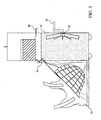
- the panel When the head cooling devices of the present invention 10 are deployed for use with a patient, the panel may be opened as shown in FIG. 2 .
- the panel 24 is attached to the main body of the head cooling device 10 via hinges at the bottom of the device.
- the panel 24 may be drawn downwards so that it rests substantially horizontal with the surface on which the heading cooling device of the present invention 10 is deployed.
- the panel 24 may lock in place to better support the patient's head.
- the panel 24 is fabricated from or includes within it an insulating material that reduces transfer of heat from the floor or ground to cooling fluid. At its distal end the panel 24 connects to a supporting cable or band 28 . The other end of the supporting cable 28 is connected to the main body of the head cooling device 10 .
- the panel 10 is supported by two such supporting cables 28 - one at the left-hand side of the panel and one at the right-hand side of the panel.
- the supporting cables 28 support a watertight chamber 30 that includes a head shroud 32 .
- the chamber 30 and head shroud 32 may be fabricated from a flexible material such as rubber or plastic.
- the watertight chamber 30 and head shroud 32 form a continuous watertight compartment that is separated from the water reservoir 16 by an internal panel 34 .
- the watertight compartment 30 preferably includes loops that are disposed around the support cables 28 .
- the head shroud 32 and hammock 36 are each preferably pre-shaped to form a pocket for the patient's head that is centrally located between the two support cables 28 .
- the shroud 32 may be physically joined to the hammock 36 as shown in FIG. 2-6 .
- the movement of the internal panel allows cooled water to be communicated from the water reservoir 16 to the shroud 32.
- the internal panel may be placed on the water reservoir side of the partition (as shown in the attached figures), or it may be placed on the patient side of the partition.
- the shroud 32 will subsequently be deployed into position by the weight of the cooling solution which will exert pressure that preferably inflates the shroud 32 into close approximation to the patient's head, as described below.
- the hammock is an entirely separate component from the watertight compartment.
- the hammock When the panel 24 is lowered in these embodiments, the hammock is, as with other embodiments, supported by the support cables 28 .
- the hammock is in place to accept the patient's head before the watertight compartment that includes the shroud is deployed in these embodiments.
- the hammock preferably includes fenestrations and is preferably connected to the wetting agent reservoir as described hereinbelow.
- the internal panel is located on the patient side of the wall of the water reservoir 16 . In such embodiments, the internal panel holds the watertight compartment and shroud on the water reservoir side of the internal panel.
- shroud straps 38 will ordinarily be fabricated either of loop-and-latch type materials such as those sold under the trademark VELCRO ®, or will consist of adhesive tabs known in the art.
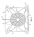
- the head hammock 36 and/or shroud 32 include fenestrations 40 as shown in FIG 2 et seq..
- the fenestrations 40 are designed to irrigate the patient shroud interface and remove air and its insulating properties from cranial hair-bearing areas.
- the hammock 36 will preferably serve two roles - supporting the head and providing an internal irrigating system.
- the wetting system reservoir 42 is preferably connected to the hammock 36 via a connector tube 44 .
- the connector tube 44 communicates wetting agent from the wetting reservoir 42 to a series of holes found in the shroud as seen in longitudinal view of FIG. 6 .
- the wetting agent is any low viscosity, conductive fluid.
- One presently preferred wetting agent is water.
- the holes 48 are preferably located in the fenestrations 40 lining the hammock 36 indentation.
- the fenestrations 40 are adapted to allow passage of wetting agent to surround the patient's head effectively.
- the apparatus of the present 10 may be utilized in the follow manner. If stored on a wall, the head cooling apparatus 10 may be initially removed from the wall and placed onto the ground such that the wheels or casters 22 contact the ground.
- the telescopic handle 20 if present, may be extended to allow easy transport of the apparatus to the patient in need of treatment.
- the latch 26 holding the panel 24 in the collapsed position may be opened and the panel 24 lowered in the deployed position as shown in FIG. 2 .
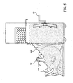
- the user may then activate a latch 50 on the outside of the head cooling device 10 that allows the endothermic reaction pellets 14 to fall into the water reservoir 16 , as shown in FIG. 3 .
- the endothermic reaction pellets 14 are ammonium nitrate. While the present application employs the term "pellets" as the form of endothermic reactant, it is to be understood that the ammonium nitrate may take the form of a combination of multiple pellet sizes or powder with pellets as described more fully hereinbelow. While the following description will employ the specific example of ammonium nitrate, other endothermic reactants are well known in the art and may be freely substituted for ammonium nitrate.
- the user may employ a rotatable mixer 18 .
- the rotatable mixer 18 is comprised of multiple spaced blades emanating radially from a center hub.
- the rotatable mixer 18 is preferably connected to an external crank handle 52 . While the head cooling device is not deployed, the crank handle 52 may be folded into the body of the device to reduce it being an obstacle to nearby pedestrian traffic. When the device is deployed, the crank handle 52 may be folded out. The crank handle 52 will allow the ammonium nitrate pellets mix thoroughly, thus promoting dissolution and effective cooling.
- the user of the head cooling device of the present invention 10 may place the patients head into the hammock 32 as shown in FIG. 4 .
- the user may then activate an actuator located on the side of the device.
- a panel 34 that lies between the water reservoir 16 and the watertight chamber is 44 altered to allow cooled fluid to drain into the watertight chamber 44 , as shown in FIG. 5 .
- the pressure caused by the influx of cooled water into the watertight chamber 44 preferably causes the shroud 32 to press firmly against the head of the patient, thereby promoting effective cooling of the cranial region of the patient.
- the shroud 32 may be secured to the patient's face through the use of the shroud straps 38 .
- Certain presently preferred embodiments of the present invention may be adapted to be recharged with endothermic solids.
- an access port (not shown) may preferably be located in the cooling chamber to allow addition of more endothermic solid, should such steps be needed during prolonged transport or treatment of the patient prior to the initiation of other cooling processes.
- the present invention may also include a deployable, detachable reservoir that includes fresh reactants. After the initially charged reactants are spent, they may be drained and the fresh reactants added from the reservoir. Alternatively, additional endothermic reactants may be added to the already charged solutions. In other present preferred embodiments, reservoirs containing additional endothermic reactant are included with the main structure of the present invention.
- the additional reactants may be discharged into the fluid reservoir surrounding the patient as needed to recharge the endothermic reaction periodically.
- Certain presently preferred embodiments of the present invention include a built-in reaction chamber thermometer which serves to guide the recharging process.
- the need for additional reactants may be assessed empirically by the user during application of the present invention to a patient.
- the water in the water reservoir and the reactant in the endothermic reactant reservoir therefore can provide, when admixed, coolant fluid for which no external refrigeration is required.
- Water and ammonium nitrate are generally employed in equal parts by weight, or at a ratio of about 1:1 by weight, and further are ordinarily incorporated into the system in the amount of 4-5 kg. each. With the combined weight of the reactants being approximately 8-10 kg., the entire system routinely weighs approximately 11-12 kg., or 25 lbs.
- Prior art head cooling devices employ a single population of ammonium nitrate pellets to participate in the endothermic reaction.
- the present invention provides an improved distribution of reactant pellets that provides for a customization of the cooling curve generated by the endothermic reaction.
- the prior art generally desired a cooling curve that did not descend below freezing, so as to avoid potential frostbite-inducing conditions, but rather achieve a constant degree of cooling. This approach, however, did not result in cooling deep brain regions, which would require a more significantly reduced surface temperature.
- the present invention specifically provides a distribution of solid ammonium nitrate that produces a "burst" of transient initial cooling that may briefly enter into subfreezing temperatures. Once the system reaches thermodynamic equilibration, the temperature will return to depressed, but above-freezing temperatures. That temperature profile more rapidly initiates therapeutic hypothermia through steeper cooling gradients than those provided in the prior art.
- thermochemical basis for the present invention a series of calometric experiments were run.
- Reactant water 120 milliliters
- the container was in turn placed into a water bath.
- Various forms of reactants were added and the temperature of the interface between the bath and the metal container was measured.
- Interface temperature rather than water bath temperature was measured to document that the patient would not be exposed to subfreezing reactant temperatures. While the water bath was not necessarily representative of the physiological patient, it nonetheless allowed the comparison of the prior art distributions of ammonium nitrate with the distributions employed by the present invention.
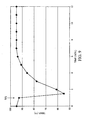
- FIG. 8 A follow-up experiment was performed ( FIG. 8 ) to assess the impact of consistent stirring on the ability of ammonium nitrate pellets to lower the reactant water, and thus the interface, temperature.
- a single packet of prior art ammonium nitrate pellets was added to the reactant water at arrow 8A .
- the reactant mixture was stirred for 30 seconds every two minutes. As may be seen, the reactant water reached a much lower temperature than without stirring ( cf. the nadirs in FIGs. 7 and 8 ) indicating that stirring has a significant impact on the operation of cooling systems.
- FIG. 10 To assess the limits of the powdered ammonium nitrate in reducing temperature, a further experiment was performed FIG. 10 . These experiments employed a water bath of reduced mass/volume in proportion to the anticipated patient head size relative to the mass of reactants used, thus simulating the clinical situation and estimating relative equilibrium points. Specifically, three packs (165 mg) of ammonium nitrate were added to 360 milliliters of reactant water at the time indicated by arrow 10A . The reactants were continuously stirred. Again, the temperature in the water bath rapidly fell and returned to a reduced temperature ( ⁇ 80°F). This result indicates that the reaction mixture was not saturated typical cold pack ratio of reactants of ammonium nitrate and that additional ammonium nitrate could be added to the system for prolonged cooling.
- FIG. 11 On the basis of the above-described experiments, an additional experiment was performed as shown in FIG. 11 .
- the experiment was designed to assess whether intermittent addition of ammonium nitrate pellets to a reaction mixture could result in improved sustained cooling.
- two packets of powdered ammonium nitrate were added to the reactant water and the reactants were continuously stirred.
- the reactant temperature dropped quickly.
- a third packet of ammonium nitrate pellets were added at the time indicated by arrow 11B .
- the temperature quickly dropped.
- Subsequent addition of ammonium nitrate at the times indicated by arrows 11C and 11D demonstrated that the reactant mixture was not saturated with ammonium nitrate and that large volumes of ammonium nitrate can effectively cool a reaction mixture.
- the present invention extrapolates from these sets of experiments to propose a novel distribution of solid endothermic reactants to be utilized in the head cooling systems of the present invention.
- the present invention accomplishes the improved cooling profile through the use of a novel distribution of solid endothermic reactant.
- the present invention includes a distribution of solid endothermic reactant having a diversity of sizes.
- the distribution includes pellets having two or more diameters.
- at least a portion of the population of pellets is of very small diameter, from approximately 2 millimeters to a finely ground powder.
- Larger pellets having an approximate diameter of about 5 to about 10 millimeters or more depending on the desired effect are also preferably included in the mixture for the maintenance of mild hypothermia after return of circulation in the patient or as part of the second phase of intra-arrest cooling/recharging.
- the preferred diameter of the large diameter pellets is 7 millimeters.
- the larger pellets would sustain cooling over a longer period of time.
- the small diameter pellets react very rapidly with the water as indicated by the above-described experiments, thereby effecting a quick and strong reduction in the temperature of the solution.
- the duration of the rapid and strong temperature reduction may be adjusted by the amount of very small diameter pellets that are included.
- the temperature will typically relax to slightly warmer temperatures, though the continued reaction of the larger pellets preferably maintains the temperature at a level sufficient to induce hypothermia.
- a customized cooling curve may be generated according to the specific applications that are intended for the cooling solution.
- the present invention contemplates inclusion of a retardant with some populations of solid endothermic reactant to achieve a similar effect as a varied distribution of pellet size. The retardant would act to slow the dissolution of the endothermic reactant and thus influence the cooling of the reaction mixture.
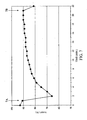
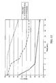
- FIG. 12 displays data collected from an animal model using a prior art head cooling device. Specifically, a 25 kg canine with similar extracranial soft tissue depth and bony thickness to adult human was employed. External hair was shaved with clippers. Temperature thermistors were surgically tunneled posteriorly between the soft tissue and the skull beginning in the neck so that transmission cables had no direct contact with cooling solution interface. Intracranial thermistors were inserted through small burr holes in the skull, epidural and thalamic, to minimize conduction through the skull defect in addition to extensive tunneling.
- Cardiac arrest was induced electrically, the animal's head was moistened, and the head cooling device applied using a single distribution of solid 4 mm ammonium nitrate pellets. Temperature was recorded in deep brain structures (thalamus), superficially in the brain (supracortical), and in a subgaleal structure (underneath the scalp muscle layer). Temperatures were recorded continuously. The reactants were subjected to intermittent stirring. As can be seen in FIG. 12 , the temperature of the superficial tissues was reduced, though deep brain structures, such as the thalamus were relatively unaffected.
- a head cooling device of the present invention as employed with a multi-component distribution of solid ammonium nitrate could be expected to produce cooling curves as displayed in FIG. 13 .
- the decreased temperature at the surface of the skin afforded by the present invention would result not only in cooling of the superficial structures, but also of deep brain structures, thus providing increased protection from hypoxic/ischemic-triggered cell death.
- This aspect of the present invention relating to nonlinear cooling curve production is also applicable to other external cooling systems, such as systems that use either reactants other than ammonium nitrate or systems that employ other mechanical cooling procedures.
Landscapes
- Health & Medical Sciences (AREA)
- Vascular Medicine (AREA)
- Thermal Sciences (AREA)
- Engineering & Computer Science (AREA)
- Biomedical Technology (AREA)
- Heart & Thoracic Surgery (AREA)
- Physics & Mathematics (AREA)
- Life Sciences & Earth Sciences (AREA)
- Animal Behavior & Ethology (AREA)
- General Health & Medical Sciences (AREA)
- Public Health (AREA)
- Veterinary Medicine (AREA)
- Thermotherapy And Cooling Therapy Devices (AREA)
Claims (13)
- Appareil pour le refroidissement rapide d'une région crânienne d'un patient, comprenant :un boîtier externe ayant une base, ledit boîtier externe renfermant :un compartiment étanche à l'eau (30) apte à former une enveloppe de protection (32) qui s'étend sur le front, le visage, le cou et un dessus, arrière et les côtés de ladite tête du patient ;un réservoir de réactif endothermique (14) contenant une quantité de réactif endothermique solide qui réagit d'une manière endothermique avec l'eau ;un réservoir d'eau (16) contenant de l'eau, comprenant une cuve structurelle qui inclut un premier panneau interne mobile qui sépare ladite cuve structurelle et ledit réservoir de réactif endothermique et un deuxième panneau interne mobile (34) qui bloque ledit compartiment étanche à l'eau contre un remplissage avec de l'eau ;un hamac apte à recevoir la tête du patient, où ledit hamac est apte à s'ajuster à l'intérieur de ladite protection ;où ledit appareil peut être stocké dans un état affaissé ;ledit appareil étant caractérisé en comprenant en outre :un panneau frontal (24) supportant ledit compartiment étanche à l'eau et fixé à sa base proximale à la base dudit boîtier externe par une charnière permettant de tirer le panneau vers le bas de sorte que ledit panneau repose horizontalement lorsqu'il se trouve en une configuration ouverte, où ledit panneau frontal est fixé à sa base distale au boîtier externe par deux bandes de support (28) s'étendant de la base distale dudit panneau audit boîtier externe à une distance au-dessus de la base du boîtier externe, où ledit hamac est supporté par lesdites bandes de support, et où ledit compartiment étanche à l'eau est situé derrière ledit panneau frontal lorsque ledit panneau frontal se trouve dans une configuration fermée lorsque ledit appareil est dans l'état affaissée.
- Appareil selon la revendication 1, comprenant en outre un mécanisme pour fixer ladite protection à la tête du patient.
- Appareil selon la revendication 1, comprenant en outre un réservoir d'agent de mouillage, où ledit réservoir d'agent de mouillage est fonctionnellement connecté audit hamac par un tube de connexion qui se termine en une série de trous dans ledit hamac.
- Appareil selon la revendication 3, dans lequel ledit hamac comprend des fenestrations qui forment des canaux autour d'un intérieur dudit hamac.
- Appareil selon la revendication 4, dans lequel ladite série de trous se situe dans lesdites fenestrations.
- Appareil selon la revendication 1, dans lequel ledit panneau frontal est un panneau isolé en dessous dudit compartiment étanche à l'eau.
- Appareil selon la revendication 1, dans lequel ledit réactif endothermique solide est le nitrate d'ammonium.
- Appareil selon la revendication 1, dans lequel ledit réactif endothermique solide est présent comme une distribution de solides, incluant des granules d'un grand diamètre et des granules d'un petit diamètre.
- Appareil selon la revendication 8, dans lequel lesdits granules d'un grand diamètre ont un diamètre entre environ 5 millimètres à environ 10 millimètres, et lesdits granules d'un petit diamètre sont de la poudre.
- Appareil selon la revendication 8, dans lequel lesdits granules d'un petit diamètre ont un diamètre d'environ 2 millimètres, et lesdits granules d'un grand diamètre ont un diamètre d'environ 7 millimètres.
- Appareil selon la revendication 1, dans lequel ledit premier panneau interne mobile est apte à être déplacé pour permettre un déplacement dudit réactif endothermique solide dudit réservoir de réactif endothermique audit réservoir d'eau.
- Appareil selon la revendication 1, dans lequel ledit deuxième panneau interne mobile est apte à être déplacé pour permettre un déplacement de l'eau dudit réservoir d'eau dans ledit compartiment étanche à l'eau.
- Appareil selon la revendication 1, comprenant en outre une poignée télescopique (20) reliée audit boîtier externe et des roues ou roulettes (22) sur le fond dudit boîtier externe.
Applications Claiming Priority (2)
| Application Number | Priority Date | Filing Date | Title |
|---|---|---|---|
| US4920308P | 2008-04-30 | 2008-04-30 | |
| PCT/US2009/042391 WO2009135054A1 (fr) | 2008-04-30 | 2009-04-30 | Appareil et procédé pour empêcher les dommages au cerveau pendant un arrêt cardiaque, une cpr ou un choc sévère |
Publications (3)
| Publication Number | Publication Date |
|---|---|
| EP2280675A1 EP2280675A1 (fr) | 2011-02-09 |
| EP2280675A4 EP2280675A4 (fr) | 2013-01-23 |
| EP2280675B1 true EP2280675B1 (fr) | 2014-04-23 |
Family
ID=41255435
Family Applications (1)
| Application Number | Title | Priority Date | Filing Date |
|---|---|---|---|
| EP09739856.4A Not-in-force EP2280675B1 (fr) | 2008-04-30 | 2009-04-30 | Appareil pour empêcher les dommages au cerveau pendant un arrêt cardiaque, une cpr ou un choc sévère |
Country Status (3)
| Country | Link |
|---|---|
| US (1) | US8449590B2 (fr) |
| EP (1) | EP2280675B1 (fr) |
| WO (1) | WO2009135054A1 (fr) |
Cited By (1)
| Publication number | Priority date | Publication date | Assignee | Title |
|---|---|---|---|---|
| US11141309B2 (en) | 2019-06-03 | 2021-10-12 | Cooler Heads Care, Inc. | Cooling cap assembly and cooling unit |
Families Citing this family (35)
| Publication number | Priority date | Publication date | Assignee | Title |
|---|---|---|---|---|
| JP4703724B2 (ja) | 2006-04-28 | 2011-06-15 | ゼルティック エステティックス インコーポレイテッド | 皮下の脂質リッチ細胞の冷却が改善された治療装置に使用する凍結防止剤 |
| US20080077201A1 (en) | 2006-09-26 | 2008-03-27 | Juniper Medical, Inc. | Cooling devices with flexible sensors |
| US8192474B2 (en) | 2006-09-26 | 2012-06-05 | Zeltiq Aesthetics, Inc. | Tissue treatment methods |
| US9132031B2 (en) | 2006-09-26 | 2015-09-15 | Zeltiq Aesthetics, Inc. | Cooling device having a plurality of controllable cooling elements to provide a predetermined cooling profile |
| US20080287839A1 (en) | 2007-05-18 | 2008-11-20 | Juniper Medical, Inc. | Method of enhanced removal of heat from subcutaneous lipid-rich cells and treatment apparatus having an actuator |
| US8523927B2 (en) | 2007-07-13 | 2013-09-03 | Zeltiq Aesthetics, Inc. | System for treating lipid-rich regions |
| EP3488833B1 (fr) | 2007-08-21 | 2025-10-22 | Zeltiq Aesthetics, Inc. | Surveillance du refroidissement de cellules riches en lipides sous-cutanés, tel que le refroidissement du tissu adipeux |
| GB2457077A (en) * | 2008-02-01 | 2009-08-05 | Julian Joshua Preston-Powers | Cooling system for headwear |
| US8603073B2 (en) | 2008-12-17 | 2013-12-10 | Zeltiq Aesthetics, Inc. | Systems and methods with interrupt/resume capabilities for treating subcutaneous lipid-rich cells |
| CA2760610C (fr) | 2009-04-30 | 2017-09-19 | Zeltiq Aesthetics, Inc. | Dispositif, systeme et procede d'elimination de chaleur a partir de cellules riches en lipide sous-cutanees |
| JP2013517897A (ja) * | 2010-01-25 | 2013-05-20 | ゼルティック エステティックス インコーポレイテッド | 熱を皮下多脂質細胞から相変化冷却剤を介して非侵襲的に除去するための家庭用アプリケータ及びそれと関連した装置、システム及び方法 |
| US8676338B2 (en) | 2010-07-20 | 2014-03-18 | Zeltiq Aesthetics, Inc. | Combined modality treatment systems, methods and apparatus for body contouring applications |
| BR112013010389A2 (pt) * | 2010-10-27 | 2017-10-31 | Cryothermic Systems | "colar de imobilização cervical com elementos de resfriamento arterial e métodos de utilização do mesmo." |
| US10722395B2 (en) | 2011-01-25 | 2020-07-28 | Zeltiq Aesthetics, Inc. | Devices, application systems and methods with localized heat flux zones for removing heat from subcutaneous lipid-rich cells |
| CN103826689B (zh) | 2011-07-25 | 2016-04-13 | 纳鲁萨夫有限公司 | 用于选择性脑部冷却的非侵入性系统、装置和方法 |
| US9259346B2 (en) * | 2011-08-11 | 2016-02-16 | Kyle E Kingsley | Method for operating a therapeutic cooling apparatus |
| US9644880B2 (en) | 2013-01-24 | 2017-05-09 | Rachel Kimia Paul | Cooling device |
| US9545523B2 (en) | 2013-03-14 | 2017-01-17 | Zeltiq Aesthetics, Inc. | Multi-modality treatment systems, methods and apparatus for altering subcutaneous lipid-rich tissue |
| US9844460B2 (en) | 2013-03-14 | 2017-12-19 | Zeltiq Aesthetics, Inc. | Treatment systems with fluid mixing systems and fluid-cooled applicators and methods of using the same |
| WO2015117036A2 (fr) | 2014-01-30 | 2015-08-06 | Zeltiq Aesthetics, Inc. | Procédés, appareils et systèmes de traitement pour améliorer l'aspect de la peau et pour effectuer d'autres traitements |
| US10675176B1 (en) | 2014-03-19 | 2020-06-09 | Zeltiq Aesthetics, Inc. | Treatment systems, devices, and methods for cooling targeted tissue |
| USD777338S1 (en) | 2014-03-20 | 2017-01-24 | Zeltiq Aesthetics, Inc. | Cryotherapy applicator for cooling tissue |
| US10952891B1 (en) | 2014-05-13 | 2021-03-23 | Zeltiq Aesthetics, Inc. | Treatment systems with adjustable gap applicators and methods for cooling tissue |
| US10568759B2 (en) | 2014-08-19 | 2020-02-25 | Zeltiq Aesthetics, Inc. | Treatment systems, small volume applicators, and methods for treating submental tissue |
| US10935174B2 (en) | 2014-08-19 | 2021-03-02 | Zeltiq Aesthetics, Inc. | Stress relief couplings for cryotherapy apparatuses |
| WO2017070112A1 (fr) | 2015-10-19 | 2017-04-27 | Zeltiq Aesthetics, Inc. | Systèmes de traitement vasculaire, dispositifs de refroidissement et procédés pour refroidir des structures vasculaires |
| CA3009414A1 (fr) | 2016-01-07 | 2017-07-13 | Zeltiq Aesthetics, Inc. | Adherence dependant de la temperature entre un applicateur et la peau pendant le refroidissement de tissu |
| US10765552B2 (en) | 2016-02-18 | 2020-09-08 | Zeltiq Aesthetics, Inc. | Cooling cup applicators with contoured heads and liner assemblies |
| US11382790B2 (en) | 2016-05-10 | 2022-07-12 | Zeltiq Aesthetics, Inc. | Skin freezing systems for treating acne and skin conditions |
| US10682297B2 (en) | 2016-05-10 | 2020-06-16 | Zeltiq Aesthetics, Inc. | Liposomes, emulsions, and methods for cryotherapy |
| US10555831B2 (en) | 2016-05-10 | 2020-02-11 | Zeltiq Aesthetics, Inc. | Hydrogel substances and methods of cryotherapy |
| US11076879B2 (en) | 2017-04-26 | 2021-08-03 | Zeltiq Aesthetics, Inc. | Shallow surface cryotherapy applicators and related technology |
| CA3107932A1 (fr) | 2018-07-31 | 2020-02-06 | Zeltiq Aesthetics, Inc. | Procedes, dispositifs et systemes pour l'amelioration d'une ou de plusieurs caracteristiques de la peau |
| US12049584B2 (en) * | 2019-03-18 | 2024-07-30 | Sabine Zureikat | Composition and method for producing the sensory stimulant |
| CN111603302A (zh) * | 2020-06-03 | 2020-09-01 | 江苏世发医疗科技有限公司 | 一种自冷式退热贴 |
Family Cites Families (10)
| Publication number | Priority date | Publication date | Assignee | Title |
|---|---|---|---|---|
| US1965424A (en) * | 1932-05-07 | 1934-07-03 | Mascolo Nino | Facial treatment apparatus |
| US4026299A (en) * | 1975-09-26 | 1977-05-31 | Vari-Temp Manufacturing Co. | Cooling and heating apparatus |
| US4304070A (en) * | 1978-05-01 | 1981-12-08 | Charles Citelli | Emergency air vent structure |
| US4265286A (en) * | 1979-07-19 | 1981-05-05 | George Rapoport | Attache case with removable file folder |
| US4920963A (en) * | 1986-02-28 | 1990-05-01 | Brader Eric W | Apparatus for preventing brain damage during cardiac arrest, CPR or severe shock |
| US6277143B1 (en) * | 1991-05-22 | 2001-08-21 | Life Science Holdings, Inc. | Brain cooling apparatus and method for cooling the brain |
| US5755756A (en) * | 1995-09-15 | 1998-05-26 | Freedman, Jr.; Robert J. | Hypothermia-inducing resuscitation unit |
| US6289889B1 (en) * | 1999-07-12 | 2001-09-18 | Tda Research, Inc. | Self-heating flexible package |
| US7040115B1 (en) * | 2004-04-23 | 2006-05-09 | Lopez Jesse M | Insulated container assembly having insertable cooling and heating gel packs |
| DE102006031944A1 (de) * | 2005-11-26 | 2007-06-06 | Joachim Siegler | Kühleinrichtung zur Absenkung der Körpertemperatur |
-
2009
- 2009-04-30 US US12/433,640 patent/US8449590B2/en not_active Expired - Fee Related
- 2009-04-30 EP EP09739856.4A patent/EP2280675B1/fr not_active Not-in-force
- 2009-04-30 WO PCT/US2009/042391 patent/WO2009135054A1/fr not_active Ceased
Cited By (2)
| Publication number | Priority date | Publication date | Assignee | Title |
|---|---|---|---|---|
| US11141309B2 (en) | 2019-06-03 | 2021-10-12 | Cooler Heads Care, Inc. | Cooling cap assembly and cooling unit |
| US11622881B2 (en) | 2019-06-03 | 2023-04-11 | Cooler Heads Care, Inc. | Cooling cap assembly and cooling unit |
Also Published As
| Publication number | Publication date |
|---|---|
| EP2280675A4 (fr) | 2013-01-23 |
| WO2009135054A1 (fr) | 2009-11-05 |
| EP2280675A1 (fr) | 2011-02-09 |
| US8449590B2 (en) | 2013-05-28 |
| US20090276018A1 (en) | 2009-11-05 |
Similar Documents
| Publication | Publication Date | Title |
|---|---|---|
| EP2280675B1 (fr) | Appareil pour empêcher les dommages au cerveau pendant un arrêt cardiaque, une cpr ou un choc sévère | |
| US4920963A (en) | Apparatus for preventing brain damage during cardiac arrest, CPR or severe shock | |
| AU2005291812B2 (en) | Cover for cooling patients and cooling device comprising a cover of this type | |
| US20240358613A1 (en) | Use of saccharides for cryoprotection and related technology | |
| US10478637B2 (en) | System and method for limiting chemotherapy-induced alopecia | |
| US20200100935A1 (en) | Temperature-dependent adhesion between applicator and skin during cooling of tissue | |
| US7422601B2 (en) | Method for inducing hypothermia | |
| US20030066304A1 (en) | Method for inducing hypothermia | |
| JP2003505190A (ja) | 低体温状態を誘導するための方法 | |
| US20150272775A1 (en) | Multi-phase mixed material therapy pack | |
| WO2003092539A2 (fr) | Methode et dispositif permettant d'induire rapidement une hypothermie | |
| Holzer | Devices for rapid induction of hypothermia | |
| EP2204150A1 (fr) | Structure froide à longue durée | |
| US20100125317A1 (en) | Long-Action Cold Pack Structure | |
| WO2011015821A1 (fr) | Dispositif de refroidissement du cerveau | |
| US20170172790A1 (en) | Temperature management and phase change energy system for storage and therapeutic applications | |
| CN100569199C (zh) | 一种治疗急性扭挫伤的外用膏药 | |
| US20140039585A1 (en) | Cold therapy device with individual compartments | |
| CN2130082Y (zh) | 自控医疗降温仪 | |
| Kutalek | Christina A. Baessler, MSN, RN Drexel University College of Medicine Philadelphia, PA |
Legal Events
| Date | Code | Title | Description |
|---|---|---|---|
| PUAI | Public reference made under article 153(3) epc to a published international application that has entered the european phase |
Free format text: ORIGINAL CODE: 0009012 |
|
| 17P | Request for examination filed |
Effective date: 20101124 |
|
| AK | Designated contracting states |
Kind code of ref document: A1 Designated state(s): AT BE BG CH CY CZ DE DK EE ES FI FR GB GR HR HU IE IS IT LI LT LU LV MC MK MT NL NO PL PT RO SE SI SK TR |
|
| AX | Request for extension of the european patent |
Extension state: AL BA RS |
|
| DAX | Request for extension of the european patent (deleted) | ||
| A4 | Supplementary search report drawn up and despatched |
Effective date: 20130104 |
|
| RIC1 | Information provided on ipc code assigned before grant |
Ipc: A61F 7/00 20060101AFI20121220BHEP |
|
| GRAP | Despatch of communication of intention to grant a patent |
Free format text: ORIGINAL CODE: EPIDOSNIGR1 |
|
| INTG | Intention to grant announced |
Effective date: 20131009 |
|
| GRAS | Grant fee paid |
Free format text: ORIGINAL CODE: EPIDOSNIGR3 |
|
| GRAP | Despatch of communication of intention to grant a patent |
Free format text: ORIGINAL CODE: EPIDOSNIGR1 |
|
| GRAA | (expected) grant |
Free format text: ORIGINAL CODE: 0009210 |
|
| INTG | Intention to grant announced |
Effective date: 20140311 |
|
| AK | Designated contracting states |
Kind code of ref document: B1 Designated state(s): AT BE BG CH CY CZ DE DK EE ES FI FR GB GR HR HU IE IS IT LI LT LU LV MC MK MT NL NO PL PT RO SE SI SK TR |
|
| REG | Reference to a national code |
Ref country code: GB Ref legal event code: FG4D |
|
| REG | Reference to a national code |
Ref country code: CH Ref legal event code: EP |
|
| REG | Reference to a national code |
Ref country code: AT Ref legal event code: REF Ref document number: 663317 Country of ref document: AT Kind code of ref document: T Effective date: 20140515 |
|
| REG | Reference to a national code |
Ref country code: IE Ref legal event code: FG4D |
|
| REG | Reference to a national code |
Ref country code: DE Ref legal event code: R096 Ref document number: 602009023476 Country of ref document: DE Effective date: 20140612 |
|
| REG | Reference to a national code |
Ref country code: AT Ref legal event code: MK05 Ref document number: 663317 Country of ref document: AT Kind code of ref document: T Effective date: 20140423 |
|
| REG | Reference to a national code |
Ref country code: NL Ref legal event code: VDEP Effective date: 20140423 |
|
| REG | Reference to a national code |
Ref country code: LT Ref legal event code: MG4D |
|
| PG25 | Lapsed in a contracting state [announced via postgrant information from national office to epo] |
Ref country code: LT Free format text: LAPSE BECAUSE OF FAILURE TO SUBMIT A TRANSLATION OF THE DESCRIPTION OR TO PAY THE FEE WITHIN THE PRESCRIBED TIME-LIMIT Effective date: 20140423 Ref country code: NO Free format text: LAPSE BECAUSE OF FAILURE TO SUBMIT A TRANSLATION OF THE DESCRIPTION OR TO PAY THE FEE WITHIN THE PRESCRIBED TIME-LIMIT Effective date: 20140723 Ref country code: NL Free format text: LAPSE BECAUSE OF FAILURE TO SUBMIT A TRANSLATION OF THE DESCRIPTION OR TO PAY THE FEE WITHIN THE PRESCRIBED TIME-LIMIT Effective date: 20140423 Ref country code: CY Free format text: LAPSE BECAUSE OF FAILURE TO SUBMIT A TRANSLATION OF THE DESCRIPTION OR TO PAY THE FEE WITHIN THE PRESCRIBED TIME-LIMIT Effective date: 20140423 Ref country code: GR Free format text: LAPSE BECAUSE OF FAILURE TO SUBMIT A TRANSLATION OF THE DESCRIPTION OR TO PAY THE FEE WITHIN THE PRESCRIBED TIME-LIMIT Effective date: 20140724 Ref country code: IS Free format text: LAPSE BECAUSE OF FAILURE TO SUBMIT A TRANSLATION OF THE DESCRIPTION OR TO PAY THE FEE WITHIN THE PRESCRIBED TIME-LIMIT Effective date: 20140823 Ref country code: FI Free format text: LAPSE BECAUSE OF FAILURE TO SUBMIT A TRANSLATION OF THE DESCRIPTION OR TO PAY THE FEE WITHIN THE PRESCRIBED TIME-LIMIT Effective date: 20140423 Ref country code: BG Free format text: LAPSE BECAUSE OF FAILURE TO SUBMIT A TRANSLATION OF THE DESCRIPTION OR TO PAY THE FEE WITHIN THE PRESCRIBED TIME-LIMIT Effective date: 20140723 |
|
| PG25 | Lapsed in a contracting state [announced via postgrant information from national office to epo] |
Ref country code: LV Free format text: LAPSE BECAUSE OF FAILURE TO SUBMIT A TRANSLATION OF THE DESCRIPTION OR TO PAY THE FEE WITHIN THE PRESCRIBED TIME-LIMIT Effective date: 20140423 Ref country code: AT Free format text: LAPSE BECAUSE OF FAILURE TO SUBMIT A TRANSLATION OF THE DESCRIPTION OR TO PAY THE FEE WITHIN THE PRESCRIBED TIME-LIMIT Effective date: 20140423 Ref country code: SE Free format text: LAPSE BECAUSE OF FAILURE TO SUBMIT A TRANSLATION OF THE DESCRIPTION OR TO PAY THE FEE WITHIN THE PRESCRIBED TIME-LIMIT Effective date: 20140423 Ref country code: ES Free format text: LAPSE BECAUSE OF FAILURE TO SUBMIT A TRANSLATION OF THE DESCRIPTION OR TO PAY THE FEE WITHIN THE PRESCRIBED TIME-LIMIT Effective date: 20140423 Ref country code: PL Free format text: LAPSE BECAUSE OF FAILURE TO SUBMIT A TRANSLATION OF THE DESCRIPTION OR TO PAY THE FEE WITHIN THE PRESCRIBED TIME-LIMIT Effective date: 20140423 Ref country code: HR Free format text: LAPSE BECAUSE OF FAILURE TO SUBMIT A TRANSLATION OF THE DESCRIPTION OR TO PAY THE FEE WITHIN THE PRESCRIBED TIME-LIMIT Effective date: 20140423 |
|
| PGFP | Annual fee paid to national office [announced via postgrant information from national office to epo] |
Ref country code: LU Payment date: 20141013 Year of fee payment: 6 |
|
| PG25 | Lapsed in a contracting state [announced via postgrant information from national office to epo] |
Ref country code: PT Free format text: LAPSE BECAUSE OF FAILURE TO SUBMIT A TRANSLATION OF THE DESCRIPTION OR TO PAY THE FEE WITHIN THE PRESCRIBED TIME-LIMIT Effective date: 20140825 |
|
| REG | Reference to a national code |
Ref country code: DE Ref legal event code: R097 Ref document number: 602009023476 Country of ref document: DE |
|
| PG25 | Lapsed in a contracting state [announced via postgrant information from national office to epo] |
Ref country code: EE Free format text: LAPSE BECAUSE OF FAILURE TO SUBMIT A TRANSLATION OF THE DESCRIPTION OR TO PAY THE FEE WITHIN THE PRESCRIBED TIME-LIMIT Effective date: 20140423 Ref country code: DK Free format text: LAPSE BECAUSE OF FAILURE TO SUBMIT A TRANSLATION OF THE DESCRIPTION OR TO PAY THE FEE WITHIN THE PRESCRIBED TIME-LIMIT Effective date: 20140423 Ref country code: CZ Free format text: LAPSE BECAUSE OF FAILURE TO SUBMIT A TRANSLATION OF THE DESCRIPTION OR TO PAY THE FEE WITHIN THE PRESCRIBED TIME-LIMIT Effective date: 20140423 Ref country code: BE Free format text: LAPSE BECAUSE OF FAILURE TO SUBMIT A TRANSLATION OF THE DESCRIPTION OR TO PAY THE FEE WITHIN THE PRESCRIBED TIME-LIMIT Effective date: 20140423 Ref country code: RO Free format text: LAPSE BECAUSE OF FAILURE TO SUBMIT A TRANSLATION OF THE DESCRIPTION OR TO PAY THE FEE WITHIN THE PRESCRIBED TIME-LIMIT Effective date: 20140423 Ref country code: SK Free format text: LAPSE BECAUSE OF FAILURE TO SUBMIT A TRANSLATION OF THE DESCRIPTION OR TO PAY THE FEE WITHIN THE PRESCRIBED TIME-LIMIT Effective date: 20140423 |
|
| PGFP | Annual fee paid to national office [announced via postgrant information from national office to epo] |
Ref country code: CH Payment date: 20141011 Year of fee payment: 6 Ref country code: IE Payment date: 20141016 Year of fee payment: 6 Ref country code: MC Payment date: 20141017 Year of fee payment: 6 Ref country code: DE Payment date: 20141031 Year of fee payment: 6 |
|
| PLBE | No opposition filed within time limit |
Free format text: ORIGINAL CODE: 0009261 |
|
| STAA | Information on the status of an ep patent application or granted ep patent |
Free format text: STATUS: NO OPPOSITION FILED WITHIN TIME LIMIT |
|
| REG | Reference to a national code |
Ref country code: FR Ref legal event code: ST Effective date: 20150210 |
|
| PG25 | Lapsed in a contracting state [announced via postgrant information from national office to epo] |
Ref country code: IT Free format text: LAPSE BECAUSE OF FAILURE TO SUBMIT A TRANSLATION OF THE DESCRIPTION OR TO PAY THE FEE WITHIN THE PRESCRIBED TIME-LIMIT Effective date: 20140423 |
|
| 26N | No opposition filed |
Effective date: 20150126 |
|
| REG | Reference to a national code |
Ref country code: DE Ref legal event code: R097 Ref document number: 602009023476 Country of ref document: DE Effective date: 20150126 |
|
| PG25 | Lapsed in a contracting state [announced via postgrant information from national office to epo] |
Ref country code: FR Free format text: LAPSE BECAUSE OF NON-PAYMENT OF DUE FEES Effective date: 20140623 |
|
| PGFP | Annual fee paid to national office [announced via postgrant information from national office to epo] |
Ref country code: GB Payment date: 20150112 Year of fee payment: 6 |
|
| PG25 | Lapsed in a contracting state [announced via postgrant information from national office to epo] |
Ref country code: SI Free format text: LAPSE BECAUSE OF FAILURE TO SUBMIT A TRANSLATION OF THE DESCRIPTION OR TO PAY THE FEE WITHIN THE PRESCRIBED TIME-LIMIT Effective date: 20140423 |
|
| REG | Reference to a national code |
Ref country code: DE Ref legal event code: R119 Ref document number: 602009023476 Country of ref document: DE |
|
| PG25 | Lapsed in a contracting state [announced via postgrant information from national office to epo] |
Ref country code: MC Free format text: LAPSE BECAUSE OF NON-PAYMENT OF DUE FEES Effective date: 20150430 Ref country code: LU Free format text: LAPSE BECAUSE OF NON-PAYMENT OF DUE FEES Effective date: 20150430 |
|
| REG | Reference to a national code |
Ref country code: CH Ref legal event code: PL |
|
| GBPC | Gb: european patent ceased through non-payment of renewal fee |
Effective date: 20150430 |
|
| REG | Reference to a national code |
Ref country code: IE Ref legal event code: MM4A |
|
| PG25 | Lapsed in a contracting state [announced via postgrant information from national office to epo] |
Ref country code: GB Free format text: LAPSE BECAUSE OF NON-PAYMENT OF DUE FEES Effective date: 20150430 Ref country code: CH Free format text: LAPSE BECAUSE OF NON-PAYMENT OF DUE FEES Effective date: 20150430 Ref country code: DE Free format text: LAPSE BECAUSE OF NON-PAYMENT OF DUE FEES Effective date: 20151103 Ref country code: LI Free format text: LAPSE BECAUSE OF NON-PAYMENT OF DUE FEES Effective date: 20150430 |
|
| PG25 | Lapsed in a contracting state [announced via postgrant information from national office to epo] |
Ref country code: IE Free format text: LAPSE BECAUSE OF NON-PAYMENT OF DUE FEES Effective date: 20150430 |
|
| PG25 | Lapsed in a contracting state [announced via postgrant information from national office to epo] |
Ref country code: HU Free format text: LAPSE BECAUSE OF FAILURE TO SUBMIT A TRANSLATION OF THE DESCRIPTION OR TO PAY THE FEE WITHIN THE PRESCRIBED TIME-LIMIT; INVALID AB INITIO Effective date: 20090430 Ref country code: TR Free format text: LAPSE BECAUSE OF FAILURE TO SUBMIT A TRANSLATION OF THE DESCRIPTION OR TO PAY THE FEE WITHIN THE PRESCRIBED TIME-LIMIT Effective date: 20140423 |
|
| PG25 | Lapsed in a contracting state [announced via postgrant information from national office to epo] |
Ref country code: MK Free format text: LAPSE BECAUSE OF FAILURE TO SUBMIT A TRANSLATION OF THE DESCRIPTION OR TO PAY THE FEE WITHIN THE PRESCRIBED TIME-LIMIT Effective date: 20140423 |
|
| PG25 | Lapsed in a contracting state [announced via postgrant information from national office to epo] |
Ref country code: MT Free format text: LAPSE BECAUSE OF NON-PAYMENT OF DUE FEES Effective date: 20150430 |
|
| PGFP | Annual fee paid to national office [announced via postgrant information from national office to epo] |
Ref country code: MT Payment date: 20140430 Year of fee payment: 6 |