EP2281789A1 - Formule de barbotine pour la fabrication de couches de protection thermiques - Google Patents
Formule de barbotine pour la fabrication de couches de protection thermiques Download PDFInfo
- Publication number
- EP2281789A1 EP2281789A1 EP20100166771 EP10166771A EP2281789A1 EP 2281789 A1 EP2281789 A1 EP 2281789A1 EP 20100166771 EP20100166771 EP 20100166771 EP 10166771 A EP10166771 A EP 10166771A EP 2281789 A1 EP2281789 A1 EP 2281789A1
- Authority
- EP
- European Patent Office
- Prior art keywords
- range
- weight percent
- dry weight
- layer
- ceramic
- Prior art date
- Legal status (The legal status is an assumption and is not a legal conclusion. Google has not performed a legal analysis and makes no representation as to the accuracy of the status listed.)
- Granted
Links
Images


Classifications
-
- C—CHEMISTRY; METALLURGY
- C04—CEMENTS; CONCRETE; ARTIFICIAL STONE; CERAMICS; REFRACTORIES
- C04B—LIME, MAGNESIA; SLAG; CEMENTS; COMPOSITIONS THEREOF, e.g. MORTARS, CONCRETE OR LIKE BUILDING MATERIALS; ARTIFICIAL STONE; CERAMICS; REFRACTORIES; TREATMENT OF NATURAL STONE
- C04B35/00—Shaped ceramic products characterised by their composition; Ceramics compositions; Processing powders of inorganic compounds preparatory to the manufacturing of ceramic products
- C04B35/01—Shaped ceramic products characterised by their composition; Ceramics compositions; Processing powders of inorganic compounds preparatory to the manufacturing of ceramic products based on oxide ceramics
- C04B35/48—Shaped ceramic products characterised by their composition; Ceramics compositions; Processing powders of inorganic compounds preparatory to the manufacturing of ceramic products based on oxide ceramics based on zirconium or hafnium oxides, zirconates, zircon or hafnates
- C04B35/486—Fine ceramics
-
- C—CHEMISTRY; METALLURGY
- C04—CEMENTS; CONCRETE; ARTIFICIAL STONE; CERAMICS; REFRACTORIES
- C04B—LIME, MAGNESIA; SLAG; CEMENTS; COMPOSITIONS THEREOF, e.g. MORTARS, CONCRETE OR LIKE BUILDING MATERIALS; ARTIFICIAL STONE; CERAMICS; REFRACTORIES; TREATMENT OF NATURAL STONE
- C04B35/00—Shaped ceramic products characterised by their composition; Ceramics compositions; Processing powders of inorganic compounds preparatory to the manufacturing of ceramic products
- C04B35/01—Shaped ceramic products characterised by their composition; Ceramics compositions; Processing powders of inorganic compounds preparatory to the manufacturing of ceramic products based on oxide ceramics
- C04B35/03—Shaped ceramic products characterised by their composition; Ceramics compositions; Processing powders of inorganic compounds preparatory to the manufacturing of ceramic products based on oxide ceramics based on magnesium oxide, calcium oxide or oxide mixtures derived from dolomite
- C04B35/04—Shaped ceramic products characterised by their composition; Ceramics compositions; Processing powders of inorganic compounds preparatory to the manufacturing of ceramic products based on oxide ceramics based on magnesium oxide, calcium oxide or oxide mixtures derived from dolomite based on magnesium oxide
-
- C—CHEMISTRY; METALLURGY
- C04—CEMENTS; CONCRETE; ARTIFICIAL STONE; CERAMICS; REFRACTORIES
- C04B—LIME, MAGNESIA; SLAG; CEMENTS; COMPOSITIONS THEREOF, e.g. MORTARS, CONCRETE OR LIKE BUILDING MATERIALS; ARTIFICIAL STONE; CERAMICS; REFRACTORIES; TREATMENT OF NATURAL STONE
- C04B35/00—Shaped ceramic products characterised by their composition; Ceramics compositions; Processing powders of inorganic compounds preparatory to the manufacturing of ceramic products
- C04B35/622—Forming processes; Processing powders of inorganic compounds preparatory to the manufacturing of ceramic products
- C04B35/62222—Forming processes; Processing powders of inorganic compounds preparatory to the manufacturing of ceramic products obtaining ceramic coatings
-
- C—CHEMISTRY; METALLURGY
- C04—CEMENTS; CONCRETE; ARTIFICIAL STONE; CERAMICS; REFRACTORIES
- C04B—LIME, MAGNESIA; SLAG; CEMENTS; COMPOSITIONS THEREOF, e.g. MORTARS, CONCRETE OR LIKE BUILDING MATERIALS; ARTIFICIAL STONE; CERAMICS; REFRACTORIES; TREATMENT OF NATURAL STONE
- C04B35/00—Shaped ceramic products characterised by their composition; Ceramics compositions; Processing powders of inorganic compounds preparatory to the manufacturing of ceramic products
- C04B35/622—Forming processes; Processing powders of inorganic compounds preparatory to the manufacturing of ceramic products
- C04B35/626—Preparing or treating the powders individually or as batches ; preparing or treating macroscopic reinforcing agents for ceramic products, e.g. fibres; mechanical aspects section B
- C04B35/63—Preparing or treating the powders individually or as batches ; preparing or treating macroscopic reinforcing agents for ceramic products, e.g. fibres; mechanical aspects section B using additives specially adapted for forming the products, e.g.. binder binders
- C04B35/6303—Inorganic additives
- C04B35/6316—Binders based on silicon compounds
-
- C—CHEMISTRY; METALLURGY
- C23—COATING METALLIC MATERIAL; COATING MATERIAL WITH METALLIC MATERIAL; CHEMICAL SURFACE TREATMENT; DIFFUSION TREATMENT OF METALLIC MATERIAL; COATING BY VACUUM EVAPORATION, BY SPUTTERING, BY ION IMPLANTATION OR BY CHEMICAL VAPOUR DEPOSITION, IN GENERAL; INHIBITING CORROSION OF METALLIC MATERIAL OR INCRUSTATION IN GENERAL
- C23C—COATING METALLIC MATERIAL; COATING MATERIAL WITH METALLIC MATERIAL; SURFACE TREATMENT OF METALLIC MATERIAL BY DIFFUSION INTO THE SURFACE, BY CHEMICAL CONVERSION OR SUBSTITUTION; COATING BY VACUUM EVAPORATION, BY SPUTTERING, BY ION IMPLANTATION OR BY CHEMICAL VAPOUR DEPOSITION, IN GENERAL
- C23C24/00—Coating starting from inorganic powder
- C23C24/08—Coating starting from inorganic powder by application of heat or pressure and heat
- C23C24/082—Coating starting from inorganic powder by application of heat or pressure and heat without intermediate formation of a liquid in the layer
-
- C—CHEMISTRY; METALLURGY
- C04—CEMENTS; CONCRETE; ARTIFICIAL STONE; CERAMICS; REFRACTORIES
- C04B—LIME, MAGNESIA; SLAG; CEMENTS; COMPOSITIONS THEREOF, e.g. MORTARS, CONCRETE OR LIKE BUILDING MATERIALS; ARTIFICIAL STONE; CERAMICS; REFRACTORIES; TREATMENT OF NATURAL STONE
- C04B2235/00—Aspects relating to ceramic starting mixtures or sintered ceramic products
- C04B2235/02—Composition of constituents of the starting material or of secondary phases of the final product
- C04B2235/30—Constituents and secondary phases not being of a fibrous nature
- C04B2235/32—Metal oxides, mixed metal oxides, or oxide-forming salts thereof, e.g. carbonates, nitrates, (oxy)hydroxides, chlorides
- C04B2235/3201—Alkali metal oxides or oxide-forming salts thereof
-
- C—CHEMISTRY; METALLURGY
- C04—CEMENTS; CONCRETE; ARTIFICIAL STONE; CERAMICS; REFRACTORIES
- C04B—LIME, MAGNESIA; SLAG; CEMENTS; COMPOSITIONS THEREOF, e.g. MORTARS, CONCRETE OR LIKE BUILDING MATERIALS; ARTIFICIAL STONE; CERAMICS; REFRACTORIES; TREATMENT OF NATURAL STONE
- C04B2235/00—Aspects relating to ceramic starting mixtures or sintered ceramic products
- C04B2235/02—Composition of constituents of the starting material or of secondary phases of the final product
- C04B2235/30—Constituents and secondary phases not being of a fibrous nature
- C04B2235/32—Metal oxides, mixed metal oxides, or oxide-forming salts thereof, e.g. carbonates, nitrates, (oxy)hydroxides, chlorides
- C04B2235/3224—Rare earth oxide or oxide forming salts thereof, e.g. scandium oxide
- C04B2235/3225—Yttrium oxide or oxide-forming salts thereof
-
- C—CHEMISTRY; METALLURGY
- C04—CEMENTS; CONCRETE; ARTIFICIAL STONE; CERAMICS; REFRACTORIES
- C04B—LIME, MAGNESIA; SLAG; CEMENTS; COMPOSITIONS THEREOF, e.g. MORTARS, CONCRETE OR LIKE BUILDING MATERIALS; ARTIFICIAL STONE; CERAMICS; REFRACTORIES; TREATMENT OF NATURAL STONE
- C04B2235/00—Aspects relating to ceramic starting mixtures or sintered ceramic products
- C04B2235/02—Composition of constituents of the starting material or of secondary phases of the final product
- C04B2235/30—Constituents and secondary phases not being of a fibrous nature
- C04B2235/34—Non-metal oxides, non-metal mixed oxides, or salts thereof that form the non-metal oxides upon heating, e.g. carbonates, nitrates, (oxy)hydroxides, chlorides
- C04B2235/3418—Silicon oxide, silicic acids or oxide forming salts thereof, e.g. silica sol, fused silica, silica fume, cristobalite, quartz or flint
-
- C—CHEMISTRY; METALLURGY
- C04—CEMENTS; CONCRETE; ARTIFICIAL STONE; CERAMICS; REFRACTORIES
- C04B—LIME, MAGNESIA; SLAG; CEMENTS; COMPOSITIONS THEREOF, e.g. MORTARS, CONCRETE OR LIKE BUILDING MATERIALS; ARTIFICIAL STONE; CERAMICS; REFRACTORIES; TREATMENT OF NATURAL STONE
- C04B2235/00—Aspects relating to ceramic starting mixtures or sintered ceramic products
- C04B2235/02—Composition of constituents of the starting material or of secondary phases of the final product
- C04B2235/30—Constituents and secondary phases not being of a fibrous nature
- C04B2235/36—Glass starting materials for making ceramics, e.g. silica glass
-
- Y—GENERAL TAGGING OF NEW TECHNOLOGICAL DEVELOPMENTS; GENERAL TAGGING OF CROSS-SECTIONAL TECHNOLOGIES SPANNING OVER SEVERAL SECTIONS OF THE IPC; TECHNICAL SUBJECTS COVERED BY FORMER USPC CROSS-REFERENCE ART COLLECTIONS [XRACs] AND DIGESTS
- Y10—TECHNICAL SUBJECTS COVERED BY FORMER USPC
- Y10T—TECHNICAL SUBJECTS COVERED BY FORMER US CLASSIFICATION
- Y10T428/00—Stock material or miscellaneous articles
- Y10T428/249921—Web or sheet containing structurally defined element or component
- Y10T428/249953—Composite having voids in a component [e.g., porous, cellular, etc.]
- Y10T428/249954—With chemically effective material or specified gas other than air, N, or carbon dioxide in void-containing component
Definitions
- the present invention relates to an improved slurry formulation (ceramic suspension) that can be used to make a thermal barrier coating, a process for making such slurry formulation, and a process for making a thermal barrier coating using such slurry formulation.
- annular combustion chambers For the construction of gas turbine combustion chambers, there are several different approaches. One of these is the use of annular combustion chambers to which the present invention relates inter alia. These are annular combustion chambers, which are arranged between the compressor and turbine substantially rotationally symmetrical about the rotor of the gas turbine. A combustible gas mixture is usually introduced into the annular combustion chamber via a plurality of burners, which burns in this and flows as an annular stream into the turbine. The substantially annular space is bounded inwardly, that is to the rotor side by a so-called inner shell or inner burner jacket and to the outside by a so-called outer shell or outer burner jacket.
- These shells often consist of several individual sections, which are welded or mechanically connected to each other and thereby form the assembly of a gas turbine.
- the individual sections can, as from the EP 1662201 be known, be designed double-walled, so that between the substantially parallel walls, a cooling air flow can be performed.
- TBC thermal barrier coating
- YSZ yttria Zirconia
- the YSZ layer can be applied by plasma spraying or by vapor deposition by electron beam.
- TBCs can, as from the DE 10 2007 001 835 known, if common materials are used as starting material, not be applied to a weld.
- the lifetime of the welded connection between the sections of the burner jacket is therefore extremely limited. Due to the high temperatures and the heat development in the combustion chamber, the shells are exposed to high thermal loads. In order to ensure a sufficient service life despite the high heat load, ring combustion chambers have been developed with various cooling methods, which are also usually combined with heat protection layers or shields.
- the one already mentioned describes DE 10 2007 001 835 a combustion chamber jacket, in which the outer shell is formed from two half-shells, which are welded together at a connecting line, and in which the inner shell is formed from two half-shells, which are also welded together at a connecting line.
- the half shells have in each case at the connection line a connecting flange which faces away from the hot side and which serves to connect the half shells to the weld seam.
- a heat shield is placed on the hot gas side of this weld seam and offset from it, which protects the weld against the high temperatures.
- the present invention relates to an improved slurry formulation (ceramic suspension) which can be used to prepare a thermal barrier coating. This in particular without the use of a separate additional bonding layer (bond coat) and also on particularly difficult materials, such as on a weld, which was not sandblasted.
- the present invention relates to a slip formulation for the preparation of a patch or strip of a thermal protection layer comprising a ceramic binder, ceramic fillers and optionally further Additives, wherein the slip formulation 20-60 dry weight percent alkali silicate binder; 40-80 dry weight percent ceramic fillers selected from the group: yttria stabilized zirconia, magnesia, or mixtures thereof; 0-20% by dry weight of additives (such as aluminum phosphates, microsilica, metakaolin, etc.), with the dry parts by weight of all the constituents completing 100%; and a solvent or suspending agent.
- additives such as aluminum phosphates, microsilica, metakaolin, etc.
- the basic adhesion of a protective layer using such a slip formulation on the substrate, in addition to the more precise surface finish, is predetermined primarily by the ceramic binder.
- water is used as the solvent or suspending agent.
- the slurry formulation has a viscosity in the range of 50-5,000 mPas, preferably 500-1500 mPas.
- such a viscosity is adjusted by adjusting the proportion of water (or more generally solvent) just before the slurry formulation is applied and during or after the mixture has been remixed.
- Suitable additives are aluminum phosphates, microsilica or metakaolin. These additives can accelerate the curing and dewatering of the layer.
- Suitable ceramic binders for the intended application are particularly alkali metal silicates with a relatively high proportion of alkali oxide (module 2-3). It is also possible to use mixtures of different alkali metal silicates. The high alkali concentration leads to etching of the metal surface and at least partial chemical bonds can form.
- the slip formulation is characterized in that the ceramic binder is an alkali silicate or a mixture of alkali silicates, preferably having a modulus in the range of 1.8-3.5, preferably sodium silicate and / or Potassium silicate and / or lithium silicate with a modulus in the range of 2-2.5 acts.
- the ceramic binder is an alkali silicate or a mixture of alkali silicates, preferably having a modulus in the range of 1.8-3.5, preferably sodium silicate and / or Potassium silicate and / or lithium silicate with a modulus in the range of 2-2.5 acts.
- M is an alkali metal ion
- y is normally a number from 0 to Is 20 and preferred values for x are in the range of 2-2.5.
- the thermal shock resistance can be influenced essentially by the fillers.
- the thermal expansion coefficient (CTE) of the filler should be as close as possible to that of the base material.
- the filler should have the lowest possible thermal conductivity, so that the best possible thermal shielding is guaranteed.
- yttria-stabilized zirconia and magnesia are suitable because their coefficients of thermal expansion best match that of Inconel.
- the fillers have a thermal expansion coefficient at room temperature in the range of 10 (10E-6 / K) - 15 (10E-6 / K), more preferably in the range of 12 (10E-6 / K) - 14 (10E-6 / K).
- other materials may also be present in typically small proportions within the scope of the fillers, as long as they do not shift the thermal expansion coefficient of the resulting layer from this area.
- the slip formulation is characterized in that the ceramic fillers have an average particle size (d50) in the range of 0.01-1 ⁇ m.
- Such a suspension allows the repair also in areas such as a weld, if preferably the substrate surface (Ni-base alloy) is ground so that a roughened and metallically pure surface is formed when, as preferred, alkali metal silicates (Li, Na, K) with relative high alkali oxide content (module 2-3.5) are used (this leads to the etching of the metal surface and chemical bonds can form), fillers such as ZrO2 and MgO are used with a thermal expansion coefficient in the vicinity of the Ni-base alloy and the grain size of the fillers in the sub- ⁇ range is selected and dispersion done with eg ultrasound. This produces fine, stable suspensions that ensure good adhesion to the substrate.
- alkali metal silicates Li, Na, K
- MgO relative high alkali oxide content
- the ceramic filler (35-60% by weight, based on the aqueous suspension) is preferably mixed with an aqueous solution of the binder and dispersed by means of an Ultra-Turrax or by ultrasound.
- the viscosity of the suspension can be adjusted so that it can be optimally processed by brushing or spraying.
- the careful dispersion of the filler ensures good deagglomeration of the powder particles and the formation of a homogeneous stable suspension.
- the present invention relates to a process for the preparation of a slip formulation, as described above, which is characterized in that an aqueous solution of the ceramic binder with the ceramic filler is added and mixed into a suspension, preferably with treatment in a mixer with fast rotating knife such as an Ultra-Turrax or under treatment with ultrasound, and optionally subsequently the viscosity is adjusted with the addition of water, preferably to a viscosity of the slip formulation in the range of 50-5000 mPas (depending on whether the suspension with the brush, the spray gun or a spatula is processed).
- a viscosity of the slip formulation in the range of 50-5000 mPas (depending on whether the suspension with the brush, the spray gun or a spatula is processed).
- coatings are carried out on Inconel substrates with the suspensions described, the layers are dried and then tested by means of the thermal shock test.
- the present invention relates to a method of constructing a region (typically localized area such as patch or strip, for example) of a thermal barrier coating with a slurry formulation as described above.
- the method is particularly characterized in that the slip formulation in 2-4 application steps (exceptionally, at most five or six application steps can be used if particularly thick layers are built up should, or it is also possible, for example, if a very thin layer is to be built to perform only one application step) of normally 0.05-0.3 mm layer order to a total layer thickness of typically 0.4-1 mm directly on a metallic substrate, typically substantially without connecting layer (in the edge region to adjacent thermal protective layer but may, for example, still be present connection layer) is applied.
- the already applied layer is preferably preliminarily dried (for example with a hair dryer at 70-80 ° C.) after each application step, and then the entire layer structure is completed in a preferably two-stage drying process or curing process.
- This two-step process involves a long-term treatment at a comparatively low temperature and a short-term treatment at a comparatively high temperature, typically the following steps: For at least 6 hours, the entire layer structure is maintained at a temperature of 80-100 ° C and then at a temperature for at least 15 minutes of at least 400 ° C.
- the total process time is less than 24 hours.
- a preferred embodiment of this method is characterized in that the surface area to be coated is cleaned prior to application of the slip formulation. This is possible, for example, using steel brushes, and / or abrasive paper and / or cleaning fluids.
- a particularly advantageous feature of the proposed slip formulation is that it is possible to carry out such a preparation of the surface without sand blasting and nevertheless to achieve sufficient adhesion to the substrate even without a bonding layer. This is particularly advantageous if, as is preferred, the method is to be used under very limited space conditions, for example within a mounted gas turbine in the combustion chamber for covering connections (welds) of wall elements thereof. If a beam treatment of the surface is required at such locations, high expenditures arise because, on the one hand, surrounding areas must be covered and, on the other hand, the blasting material has to be removed again from the adjacent and surrounding areas after the treatment.
- a further preferred embodiment of the method is characterized in that the slip formulation is applied in each case with the aid of a brush, a roller, a spatula and / or a pointed gun.
- the proposed slip formulation allows to dispense with expensive application methods such as plasma processes, which makes it possible to use the proposed method even in very limited space, for example as described above within a mounted gas turbine combustion chamber and without excessive equipment expense.
- it is dried and cured for at least 6 hours at a temperature of in the range of 95 ° C and then for 15-30 minutes at a temperature in the range of 400 ° C.
- drying attachment can often be designed for all welds due to the symmetry of a combustion chamber and the welds used (typically axially extending and, accordingly, all welds are arranged in a same or at least similar surface topology).
- the area to be covered with the new layer is a weld, in particular a weld between half-shells (or quarter shells) for a combustion chamber.
- the drying attachment in particular has the form of a box open on one side and covering substantially only the coated area or a cover whose inside can prefer or accelerate the drying and / or hardening, for example by applying hot air to the inside or the inside cavity an electric resistance heater is heated (light energy or another form of energy can be registered).
- the drying attachment is provided with an insulating layer substantially along all its walls (laterally and upwardly).
- a further preferred embodiment of the proposed method is characterized in that it is carried out for coating areas exposed to hot gas flow in a gas turbine with a gas turbine which is essentially composed in the corresponding area.
- the method can therefore be used for coating the weld seam between wall regions of the combustion chamber, typically adjacent to already existing thermal protection layers on the adjoining wall regions.
- thermal protection layers which are provided on the inside of the wall areas before assembly, preferably have a thickness in the range of 0.4-1.5 mm.
- the thermal protective layers normally do not extend all the way to the edge where the weld seam is arranged, typically a surface strip of a width of 5-15 mm is not provided with such a thermal protective layer in the edge region of the wall regions.
- the present invention relates to a combustion chamber (or a gas turbine having such a combustion chamber) with at least one combustion chamber wall joined with elements joined by welds, wherein at least one weld seam having a protective layer area (patch, strip) prepared by a method as described above immediately (that is typically substantially without connecting layer or at most in the edge region with connecting layer) is covered.
- a combustion chamber or a gas turbine having such a combustion chamber
- at least one combustion chamber wall joined with elements joined by welds wherein at least one weld seam having a protective layer area (patch, strip) prepared by a method as described above immediately (that is typically substantially without connecting layer or at most in the edge region with connecting layer) is covered.
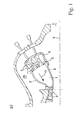
- Fig. 1 a shows a section through the middle part of a gas turbine, that is, the area between the compressor and turbine and the final stage of the compressor and the first stage of the turbine.
- a compressor 7 compresses the air. Most of the air is introduced via the Kompressplplenum 28 in an annular combustion chamber 1 and mixed with fuel, which burns there. From there, the hot fuel gases 10 flow under working discharge through a turbine 8, which rotates about an axis 9.
- the annular combustion chamber 1 is enclosed by an outer shell 3, an inner shell 2 and a front plate 5, through which fuel is introduced via burner 4 of the fuel premixed with compressed air.
- a portion of the compressor discharge air is before the introduction into the annular combustion chamber 1 on the inner shell 2 and outer shell 3 to Cooling passed along.
- To guide the cooling air is normally provided around the Brennschschen2, 3, an outer cooling air duct cover and an inner cooling air duct cover each in the form of cover plates.
- a burner cap 6 is arranged at the outlet of the cooling air guiding shell, in which there is a pressure below the compressor plenum pressure. From this, the air flows through the burner 4 or as a faceplate cooling air in the annular combustion chamber 1.
- the pressure loss between Kompressplenum 28 and annular combustion chamber 1 is thus divided into a part for the shell cooling and a part for front plate cooling or admixture in the burner 4.
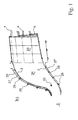
- FIG. 1 b shows a slightly different construction an annular combustion chamber, in which it has a first zone 23 which is segmented, and a second zone 24, which is circumferential.
- Inner shell 2 and outer shell 3 delimit this second zone 24.
- inner shell 2 and / or outer shell 3 typically have flange-like extensions, which are remote from the combustion chamber.
- the outer cooling air guide sheath and the inner cooling air duct cover can be seen, these are each in the form of cover plates 25, which are fastened with simultaneously serving as a spacer fasteners 26 to inner shell 2 and outer shell 3 on the outside.
- a channel 27 for guiding the cooling air as explained above is formed between the respective shell and the corresponding shell.
- Inner shell 2 and outer shell 3 are typically formed in the form of half shells guided around the burner axis by 180 °, in each case a lower half shell and an upper half shell.
- the lower half shell is specified, inserted axially to be attached central elements and then placed in each case the upper half shell.
- the inner half-shells 2a and 2b then abut against each other at edges lying substantially in a horizontal plane, and the outer half-shells 3a and 3b also butt against each other at edges lying substantially in a same horizontal plane (see, for example Fig. 2a ', 2b' ).
- the half-shells are connected with the help of a welding process after assembly, that is under very limited space.
- a substantially continuous sheathing surface for the combustion chamber is formed.
- this connecting line ie the weld at the abutment between the adjacent edges of the shroud sections
- the object of the invention is to be able to apply a thermal protective layer in this region of the connecting line, although the elements are already assembled and correspondingly the most difficult space conditions prevail.
- the sheets which form the half shells 2a / 2b and 3a / 3b, respectively, are provided on their side facing the combustion chamber over almost the entire surface with a thermal protection layer.
- Their typical structure is made FIG. 3 seen.
- a metallic-based bond coat 19 typically based on Ni, Al and Cr, or Co, Ni, Al and Cr, or Pt and Al based alloys, is disposed on the metallic base 2/3.
- the coatings may also be present in the form of structures of the formula III, where M is at least one element selected from the group Fe, Ni, Co, for example in the form of MAl, MAlY, MCrAl, MCrAlY or else PtAl.
- M is selected from the group Ni, Co, Fe and combinations thereof;
- X is an element selected from the group consisting of Y, Ta, Si, Hf, Ti, Zr, B, C and combinations thereof.
- a ceramic thermal protection layer 20 is arranged on this connection layer 19, which typically only adheres sufficiently to the substrate 2/3 as a result of the connection-mediating connection layer 19.
- This ceramic layer 20 is normally composed of 6-8% by weight yttria-stabilized zirconia (YSZ) as disclosed in U.S. Pat US 4,485,151 is known.
- YSZ yttria-stabilized zirconia
- thermal protection layer 21 the structure of bonding layer 19 and ceramic layer 20 will be referred to as thermal protection layer 21.
- the metallic interconnect layers and the ceramic layer can be applied with the aid of vapor deposition such as PVD, CVD, or thermal spraying methods, as well as plasma spray methods.
- the surfaces facing the combustion chamber do not have such a thermal protection layer 21, normally via a strip running along the edge, whereby a total exposed width of approximately 30 mm is produced, that is Each sheet has at the edge over a width of 10-15 mm does not have such a thermal protection layer. This, then to the formation of a weld 16 too enable.
- the present invention proposes both a new slurry formulation (ceramic suspension) which can be used under these conditions, as well as a novel rapid and straightforward process for applying such a slurry formulation for the construction of a thermal protection layer of sufficient thickness.
- the newly proposed slip formulation essentially comprises a ceramic binder, ceramic fillers and optionally other additives.
- the ceramic binder is substantially responsible for adhesion to the substrate, especially in the present situation where a metallic bond coat is desired.
- the thermal shock resistance is strongly influenced by the fillers.
- the thermal expansion coefficient of the filler should be as close as possible to that of the base material (substrate).
- the filler should have the lowest possible thermal conductivity, so as to ensure the highest possible thermal shielding.
- such a slip formulation is applied to a metallic surface (rolled material, milled material, with or without weld, for example between two half-shells for a combustion chamber) with a spatula, a roll, a brush or with an air spray in a few steps (not more than four application steps) applied and each between them dried until a layer thickness in the range of 0.4-1 mm is reached and finally dried and cured at the end.
- a metallic surface rolled material, milled material, with or without weld, for example between two half-shells for a combustion chamber
- a spatula, a roll, a brush or with an air spray in a few steps (not more than four application steps) applied and each between them dried until a layer thickness in the range of 0.4-1 mm is reached and finally dried and cured at the end.
- Inconel substrates 60x40x7mm
- sandpaper 50-90 grit
- This surface is then cleaned with organic solvents and degreased.
- the ceramic suspension is then applied in several layers until a total layer thickness of 0.2-0.8 mm is achieved (single layer thickness about 0.1-0.2 mm).
- the individual layers are e.g. with a hair dryer between 70 - 80 ° C for 1-3 minutes. The final drying of the whole layer takes place in an oven at 75-95 ° C for 4-16 hours.
- the performance of the layers thus produced is then tested in a thermal shock test at 1000 ° C.
- the sample is alternately immersed in a fluidized sand bath at 1000 ° C or 20 ° C.
- the number of cycles that the coating survives until first spalling occurs is referred to as the life of the layer.
- the layers produced with the described suspensions and the described method have reached 300-500 cycles in the thermal shock test, which is the requirement more than fulfilled for the planned application.
- aqueous sodium silicate solution (modulus 2.5, about 40% by weight of sodium silicate in water) are mixed with 96 g of yttria-stabilized zirconium oxide having an average particle size of 0.3 ⁇ m and stirred well with a wooden spatula.
- the mixture is then sonicated for 15 minutes. It forms a moderately viscous, homogeneous stable suspension, which can be well processed with a brush or a spray gun.
- aqueous alkali silicate solution As aqueous alkali silicate solution, however, a mixture of 60 g of the same sodium silicate solution (module 2.5) and 40 g of potassium silicate solution (module 2.4, about 35% by weight potassium silicate in water) is used. It also forms a homogeneous stable suspension, which can be processed well.
- Example 1 As a filler but 67 g of magnesium oxide are used with an average particle size of 0.05 microns. Also in this case, a homogeneous stable suspension with good processing properties.
- the substrate is previously sanded with 50-grit sandpaper and rinsed with acetone. After evaporation of the solvent, the sample is positioned vertically in a spray booth and coated step by step 5 times with the spray gun.
- the individual layers are then dried with the hair dryer for 2 minutes. Due to the optimized viscosity of the suspension, the individual layers do not run off and it forms a smooth homogeneous overall layer. The final drying takes place in the oven at 80 ° C for 10 hours. With a layer thickness gauge (eddy current method), a layer thickness of 0.4-0.5 mm is measured after drying.
- FIG. 2 shows two sectional views of a layer region 22 which can be produced by the proposed method.
- the respective half shells 2a / 2b and 3a / 3b abut one another (typically with flanks chamfered in a V) and the weld seam 16 is arranged on this joint.
- On the respective half-shells 2/3 is on the hot gas side 17 facing top - in contrast to the uncoated back 18 - already built a previously applied classic thermal protection layer 21, this includes, as already explained above, a compound layer 19 and on this the hot gas side 17th facing ceramic layer 20.
- the half-shells 2/3 are not equipped with such a thermal protection layer 21, ie over a width W 1 of about 15 mm, the metallic material of the elements 2/3 is simply exposed at each element on the edge.
- a chamfer 30 of the thermal protection layer 21 may be provided so that the subsequently applied strip 22 adheres better in the edge region.
- the width of the uncoated edge area including bevel / outlet zone W 2 is correspondingly increased compared to W 1 .
- the protective layer 22 is then applied to the weld seam 16 and to the upper-side exposed area of the elements 2/3. This can, on the one hand, as in FIG. 3a shown, done so that the surface of the region 22 is substantially flush with the surrounding layer 21 and a smooth surface is formed.
- the proposed protective layer 22 may also, as shown in FIG. 4 is simply used to make patches on a surface. It is thus not necessary for the protective layer 22 to be to some extent interposed between already existing regions of thermal protection layers 21, as shown in FIG. 3 is shown. Be like in FIG. 4 If such patches or strips are applied individually, then it proves to be advantageous to apply these patches or stripes on the patches Leaking edge with a discharge area of a width a of about 5 mm. Otherwise, the edge areas are too heavily loaded and can jump off.
- drying attachments can advantageously be used for the drying steps, as described in US Pat FIG. 2 are shown.
- FIG. 2a and 2a ' a first construction of such a drying attachment 11 is shown. It is in this construction is a box-shaped construction, in which to some extent a downwardly open and with an insulating layer 29 (this layer may be provided outside or inside with respect to a wall) provided box with a straight upper wall has lateral walls which the curvature in this case, the outer burner casing is adapted. Such a box, optionally using seals in the contact area 14, on the combustion chamber wall, the weld seam 16 are placed overlapping (see. FIG. 2a ' ).
- this box 11 is acted upon with hot air along the box 11 extending line 12 (for example, copper pipe) is provided, this line has holes (perforations), so that the hot air 13 distributed over the entire length of the box 11 flows out of this line 12 and so the entire weld 16 where a protective layer is applied, heat and so dry / harden (in the FIGS. 2a 'and 2b' in each case the applied protective layers are not shown for better visualization).
- line 12 for example, copper pipe
- this line has holes (perforations), so that the hot air 13 distributed over the entire length of the box 11 flows out of this line 12 and so the entire weld 16 where a protective layer is applied, heat and so dry / harden (in the FIGS. 2a 'and 2b' in each case the applied protective layers are not shown for better visualization).
- FIG. 2b an alternative design is shown. While a box behind FIG. 2a At the highest point it may well have a height of about 15 cm, this at a width of about 7-12 cm, the construction is according to FIG. 2b considerably flatter and has a height of about 2-4 cm with a width of about 7-16 cm.
- the box used here nestles over its entire length substantially to the contour of the combustion chamber and is located directly above the weld seam 16 to form a cavity with a small volume. In this cavity and attached to the drying attachment 11 heating wires 15 are arranged. For drying a protective layer 22, this elongated box or better this elongate cover is placed on the newly created protective layer 22 and the heater is connected to an electrical power source. Again, the box 11 is provided with an insulating layer 29.
Landscapes
- Chemical & Material Sciences (AREA)
- Engineering & Computer Science (AREA)
- Ceramic Engineering (AREA)
- Organic Chemistry (AREA)
- Materials Engineering (AREA)
- Manufacturing & Machinery (AREA)
- Structural Engineering (AREA)
- Inorganic Chemistry (AREA)
- Chemical Kinetics & Catalysis (AREA)
- Mechanical Engineering (AREA)
- Metallurgy (AREA)
- Composite Materials (AREA)
- Other Surface Treatments For Metallic Materials (AREA)
- Turbine Rotor Nozzle Sealing (AREA)
Applications Claiming Priority (1)
| Application Number | Priority Date | Filing Date | Title |
|---|---|---|---|
| CH01014/09A CH701373A1 (de) | 2009-06-30 | 2009-06-30 | Schlickerformulierung zur Herstellung von thermischen Schutzschichten. |
Publications (2)
| Publication Number | Publication Date |
|---|---|
| EP2281789A1 true EP2281789A1 (fr) | 2011-02-09 |
| EP2281789B1 EP2281789B1 (fr) | 2016-09-14 |
Family
ID=41168586
Family Applications (1)
| Application Number | Title | Priority Date | Filing Date |
|---|---|---|---|
| EP10166771.5A Not-in-force EP2281789B1 (fr) | 2009-06-30 | 2010-06-22 | Formule de barbotine pour la fabrication de couches de protection thermiques |
Country Status (3)
| Country | Link |
|---|---|
| US (1) | US8758502B2 (fr) |
| EP (1) | EP2281789B1 (fr) |
| CH (1) | CH701373A1 (fr) |
Cited By (2)
| Publication number | Priority date | Publication date | Assignee | Title |
|---|---|---|---|---|
| WO2020035474A1 (fr) | 2018-08-13 | 2020-02-20 | HÜTTENES-ALBERTUS Chemische Werke Gesellschaft mit beschränkter Haftung | Utilisation d'une composition de poteyage et procédé correspondant de fabrication d'une coquille de coulée centrifuge pourvue d'un revêtement de poteyage |
| US12018175B2 (en) | 2018-06-28 | 2024-06-25 | Nihon Parkerizing Co., Ltd. | Surface treatment agent for metal materials, metal material coated with surface treatment film, and method for producing same |
Families Citing this family (22)
| Publication number | Priority date | Publication date | Assignee | Title |
|---|---|---|---|---|
| AT508322B1 (de) * | 2009-06-05 | 2012-04-15 | Boehler Schmiedetechnik Gmbh & Co Kg | Verfahren zur warmformgebung eines werkstückes |
| BR122020020238B1 (pt) * | 2011-12-19 | 2021-09-08 | Praxair S.T. Technology, Inc | Composição de pasta fluida, revestimento de barreira térmica ou ambiental, e, métodos para produção de uma pasta fluida aquosa, e para aplicar um revestimento de barreira térmica ou ambiental com uma pasta fluida aquosa |
| US20130177439A1 (en) * | 2012-01-11 | 2013-07-11 | General Electric Company | Creep resistant coating for ceramic turbine blades |
| US9139477B2 (en) | 2013-02-18 | 2015-09-22 | General Electric Company | Ceramic powders and methods therefor |
| WO2014142017A1 (fr) | 2013-03-13 | 2014-09-18 | 株式会社 フジミインコーポレーテッド | Bouillie pour pulvérisation thermique, film de pulvérisation thermique, et procédé de formation d'un film de pulvérisation thermique |
| US10377905B2 (en) | 2013-03-13 | 2019-08-13 | Fujimi Incorporated | Slurry for thermal spraying, thermal sprayed coating, and method for forming thermal sprayed coating |
| JP6291069B2 (ja) | 2014-09-03 | 2018-03-14 | 株式会社フジミインコーポレーテッド | 溶射用スラリー、溶射皮膜および溶射皮膜の形成方法 |
| EP3141631B1 (fr) | 2015-09-10 | 2018-03-14 | Rolls-Royce High Temperature Composites Inc | Application de couche de liaison contenant du silicium metal sur des substrats en ceramique ou en composite a matrice ceramique |
| JP6741410B2 (ja) | 2015-09-25 | 2020-08-19 | 株式会社フジミインコーポレーテッド | 溶射用スラリー、溶射皮膜および溶射皮膜の形成方法 |
| US10994287B2 (en) | 2016-12-02 | 2021-05-04 | General Electric Company | Coating system and method |
| US10589300B2 (en) | 2016-12-02 | 2020-03-17 | General Electric Company | Coating system and method |
| US11067002B2 (en) | 2016-12-06 | 2021-07-20 | General Electric Company | Gas turbine engine maintenance tool |
| US10364701B2 (en) | 2016-12-06 | 2019-07-30 | General Electric Company | CMAS barrier coating for a gas turbine engine having a reactive material that reacts with a layer of environmental contaminant compositions and method of applying the same |
| US10744355B2 (en) * | 2017-03-29 | 2020-08-18 | Goodrich Corporation | Heat resistant systems and methods |
| US11161128B2 (en) | 2017-11-14 | 2021-11-02 | General Electric Company | Spray nozzle device for delivering a restorative coating through a hole in a case of a turbine engine |
| US10710109B2 (en) | 2017-11-14 | 2020-07-14 | General Electric Company | Spray nozzle device for delivering a restorative coating through a hole in a case of a turbine engine |
| US11534780B2 (en) | 2017-11-14 | 2022-12-27 | General Electric Company | Spray nozzle device for delivering a restorative coating through a hole in a case of a turbine engine |
| US10697634B2 (en) * | 2018-03-07 | 2020-06-30 | General Electric Company | Inner cooling shroud for transition zone of annular combustor liner |
| US11760696B2 (en) * | 2019-01-04 | 2023-09-19 | Rtx Corporation | Ceramic matrix composite component with modified thermal expansion and method for producing the same |
| CN110484854B (zh) * | 2019-07-22 | 2021-04-23 | 中国航发北京航空材料研究院 | 一种具有自修复和温敏功能的热障涂层的制备方法 |
| SG10202010783RA (en) | 2019-11-06 | 2021-06-29 | Gen Electric | Restoration coating system and method |
| EP4063536A1 (fr) * | 2021-03-24 | 2022-09-28 | The Boeing Company | Procédés et compositions d'inhibition de l'alpha case sur des surfaces d'alliage de titane |
Citations (7)
| Publication number | Priority date | Publication date | Assignee | Title |
|---|---|---|---|---|
| US4485151A (en) | 1982-05-06 | 1984-11-27 | The United States Of America As Represented By The Administrator Of The National Aeronautics And Space Administration | Thermal barrier coating system |
| EP0396240A1 (fr) * | 1989-05-05 | 1990-11-07 | Kaman Sciences Corporation | Matériau céramique et son procédé de fabrication |
| EP1471043A2 (fr) * | 2003-04-22 | 2004-10-27 | General Electric Company | Procédé in-situ et composition pour la réparation d'un revêtement de barrière thermique |
| EP1662201A2 (fr) | 2004-11-30 | 2006-05-31 | Alstom Technology Ltd | Tuile et structure exosquelettique de tuiles |
| EP1739204A2 (fr) * | 2005-06-29 | 2007-01-03 | The General Electric Company | Revêtement haute température lisse usure réparable |
| DE102007001835A1 (de) | 2006-01-14 | 2007-08-02 | Alstom Technology Ltd. | Vergasungsbrenner-Ummantelungen |
| WO2009040286A1 (fr) | 2007-09-24 | 2009-04-02 | Alstom Technology Ltd | Turbine à gaz à enveloppes de chambre à combustion soudées |
Family Cites Families (3)
| Publication number | Priority date | Publication date | Assignee | Title |
|---|---|---|---|---|
| US4871694A (en) * | 1986-03-17 | 1989-10-03 | Legare David J | Cellular ceramic material and method of production thereof |
| US5985470A (en) * | 1998-03-16 | 1999-11-16 | General Electric Company | Thermal/environmental barrier coating system for silicon-based materials |
| US20080026248A1 (en) * | 2006-01-27 | 2008-01-31 | Shekar Balagopal | Environmental and Thermal Barrier Coating to Provide Protection in Various Environments |
-
2009
- 2009-06-30 CH CH01014/09A patent/CH701373A1/de not_active Application Discontinuation
-
2010
- 2010-06-22 EP EP10166771.5A patent/EP2281789B1/fr not_active Not-in-force
- 2010-06-30 US US12/826,798 patent/US8758502B2/en not_active Expired - Fee Related
Patent Citations (8)
| Publication number | Priority date | Publication date | Assignee | Title |
|---|---|---|---|---|
| US4485151A (en) | 1982-05-06 | 1984-11-27 | The United States Of America As Represented By The Administrator Of The National Aeronautics And Space Administration | Thermal barrier coating system |
| EP0396240A1 (fr) * | 1989-05-05 | 1990-11-07 | Kaman Sciences Corporation | Matériau céramique et son procédé de fabrication |
| EP1471043A2 (fr) * | 2003-04-22 | 2004-10-27 | General Electric Company | Procédé in-situ et composition pour la réparation d'un revêtement de barrière thermique |
| US20070134408A1 (en) * | 2004-04-07 | 2007-06-14 | General Electric Company | Field repairable high temperature smooth wear coating |
| EP1662201A2 (fr) | 2004-11-30 | 2006-05-31 | Alstom Technology Ltd | Tuile et structure exosquelettique de tuiles |
| EP1739204A2 (fr) * | 2005-06-29 | 2007-01-03 | The General Electric Company | Revêtement haute température lisse usure réparable |
| DE102007001835A1 (de) | 2006-01-14 | 2007-08-02 | Alstom Technology Ltd. | Vergasungsbrenner-Ummantelungen |
| WO2009040286A1 (fr) | 2007-09-24 | 2009-04-02 | Alstom Technology Ltd | Turbine à gaz à enveloppes de chambre à combustion soudées |
Cited By (2)
| Publication number | Priority date | Publication date | Assignee | Title |
|---|---|---|---|---|
| US12018175B2 (en) | 2018-06-28 | 2024-06-25 | Nihon Parkerizing Co., Ltd. | Surface treatment agent for metal materials, metal material coated with surface treatment film, and method for producing same |
| WO2020035474A1 (fr) | 2018-08-13 | 2020-02-20 | HÜTTENES-ALBERTUS Chemische Werke Gesellschaft mit beschränkter Haftung | Utilisation d'une composition de poteyage et procédé correspondant de fabrication d'une coquille de coulée centrifuge pourvue d'un revêtement de poteyage |
Also Published As
| Publication number | Publication date |
|---|---|
| US8758502B2 (en) | 2014-06-24 |
| US20100330282A1 (en) | 2010-12-30 |
| CH701373A1 (de) | 2010-12-31 |
| EP2281789B1 (fr) | 2016-09-14 |
Similar Documents
| Publication | Publication Date | Title |
|---|---|---|
| EP2281789B1 (fr) | Formule de barbotine pour la fabrication de couches de protection thermiques | |
| DE60021178T2 (de) | Abrasions- und hochtemperaturbeständige, abschleifbare wärmedämmende verbundbeschichtung | |
| DE69707365T2 (de) | Isolierendes, wärmedämmendes Beschichtungssystem | |
| DE60103612T2 (de) | Verfahren zum Reparieren einer keramischen Beschichtung | |
| EP3419783A1 (fr) | Procédé de fabrication d'une pièce par enduction et fabrication additive ; pièce correspondante | |
| DE19824792B4 (de) | Verfahren zum Herstellen einer Haftschicht für eine Wärmedämmschicht | |
| EP1522604A1 (fr) | Système de couches et procédé pour sa fabrication | |
| EP2826959A2 (fr) | Procédé de fabrication d'un élément d'isolation et élément d'isolation pour un carter d'un groupe motopropulseur | |
| DE3307749A1 (de) | Bauteil mit einem kompositwerkstoff-ueberzug und verfahren zum aufbringen des ueberzugs | |
| EP3458431B1 (fr) | Procédé de fabrication d'un écran thermique céramique à revêtement de réaction | |
| DE102019122029A1 (de) | Schützen eines lochs in der komponente während des beschichtungsprozesses mit einem stopfen mit wasserlöslicher schicht | |
| DE112017005103B4 (de) | Wärmedämmschicht, turbinenelement, und wärmedämmschichtverfahren | |
| EP2882939A1 (fr) | Procédé de reconditionnement d'une aube de turbine à gaz ainsi que turbine à gaz pourvue d'une telle aube | |
| EP1097249B1 (fr) | Procede de realisation d'un blindage pour un composant metallique | |
| WO2012051978A2 (fr) | Pièce et procédé pour concevoir, réparer et/ou construire une pièce de ce type | |
| EP1522375A1 (fr) | Procédé de fabrication d'un système multicouche | |
| EP1639152A1 (fr) | Procede de fabrication d'une couche de protection, couche de protection, utilisation de celle-ci et composant comportant une couche de protection | |
| EP1967615A1 (fr) | Procédé destiné à l'application d'une couche d'isolation thermique et pièce de turbine dotée d'une couche d'isolation thermique | |
| EP1645652A1 (fr) | Procédé de fabrication d'un système de couches | |
| EP3428308A1 (fr) | Procédé de revêtement d'un composant pour le canal de gaz chaud d'une turbomachine | |
| WO2018072970A1 (fr) | Écran thermique céramique à infiltration de surface servant à éviter la corrosion et les attaques par érosion | |
| EP3493931A1 (fr) | Procédé de fabrication d'une structure de conduit et constituants | |
| WO2007144217A1 (fr) | Procédé d'application d'un matériau sur un composant | |
| EP1931811A1 (fr) | Composition seche, son utilisation et procede de revetement | |
| EP1811055A1 (fr) | Methode pour fabriquer un composant avec des orifices |
Legal Events
| Date | Code | Title | Description |
|---|---|---|---|
| PUAI | Public reference made under article 153(3) epc to a published international application that has entered the european phase |
Free format text: ORIGINAL CODE: 0009012 |
|
| AK | Designated contracting states |
Kind code of ref document: A1 Designated state(s): AL AT BE BG CH CY CZ DE DK EE ES FI FR GB GR HR HU IE IS IT LI LT LU LV MC MK MT NL NO PL PT RO SE SI SK SM TR |
|
| AX | Request for extension of the european patent |
Extension state: BA ME RS |
|
| 17P | Request for examination filed |
Effective date: 20110802 |
|
| 17Q | First examination report despatched |
Effective date: 20140704 |
|
| GRAP | Despatch of communication of intention to grant a patent |
Free format text: ORIGINAL CODE: EPIDOSNIGR1 |
|
| INTG | Intention to grant announced |
Effective date: 20160404 |
|
| GRAS | Grant fee paid |
Free format text: ORIGINAL CODE: EPIDOSNIGR3 |
|
| GRAA | (expected) grant |
Free format text: ORIGINAL CODE: 0009210 |
|
| RAP1 | Party data changed (applicant data changed or rights of an application transferred) |
Owner name: GENERAL ELECTRIC TECHNOLOGY GMBH |
|
| AK | Designated contracting states |
Kind code of ref document: B1 Designated state(s): AL AT BE BG CH CY CZ DE DK EE ES FI FR GB GR HR HU IE IS IT LI LT LU LV MC MK MT NL NO PL PT RO SE SI SK SM TR |
|
| REG | Reference to a national code |
Ref country code: GB Ref legal event code: FG4D Free format text: NOT ENGLISH |
|
| REG | Reference to a national code |
Ref country code: CH Ref legal event code: EP |
|
| REG | Reference to a national code |
Ref country code: IE Ref legal event code: FG4D Free format text: LANGUAGE OF EP DOCUMENT: GERMAN |
|
| REG | Reference to a national code |
Ref country code: AT Ref legal event code: REF Ref document number: 828784 Country of ref document: AT Kind code of ref document: T Effective date: 20161015 |
|
| REG | Reference to a national code |
Ref country code: DE Ref legal event code: R096 Ref document number: 502010012394 Country of ref document: DE |
|
| REG | Reference to a national code |
Ref country code: LT Ref legal event code: MG4D |
|
| REG | Reference to a national code |
Ref country code: NL Ref legal event code: MP Effective date: 20160914 |
|
| PG25 | Lapsed in a contracting state [announced via postgrant information from national office to epo] |
Ref country code: NO Free format text: LAPSE BECAUSE OF FAILURE TO SUBMIT A TRANSLATION OF THE DESCRIPTION OR TO PAY THE FEE WITHIN THE PRESCRIBED TIME-LIMIT Effective date: 20161214 Ref country code: FI Free format text: LAPSE BECAUSE OF FAILURE TO SUBMIT A TRANSLATION OF THE DESCRIPTION OR TO PAY THE FEE WITHIN THE PRESCRIBED TIME-LIMIT Effective date: 20160914 Ref country code: LT Free format text: LAPSE BECAUSE OF FAILURE TO SUBMIT A TRANSLATION OF THE DESCRIPTION OR TO PAY THE FEE WITHIN THE PRESCRIBED TIME-LIMIT Effective date: 20160914 Ref country code: HR Free format text: LAPSE BECAUSE OF FAILURE TO SUBMIT A TRANSLATION OF THE DESCRIPTION OR TO PAY THE FEE WITHIN THE PRESCRIBED TIME-LIMIT Effective date: 20160914 |
|
| PG25 | Lapsed in a contracting state [announced via postgrant information from national office to epo] |
Ref country code: LV Free format text: LAPSE BECAUSE OF FAILURE TO SUBMIT A TRANSLATION OF THE DESCRIPTION OR TO PAY THE FEE WITHIN THE PRESCRIBED TIME-LIMIT Effective date: 20160914 Ref country code: GR Free format text: LAPSE BECAUSE OF FAILURE TO SUBMIT A TRANSLATION OF THE DESCRIPTION OR TO PAY THE FEE WITHIN THE PRESCRIBED TIME-LIMIT Effective date: 20161215 Ref country code: ES Free format text: LAPSE BECAUSE OF FAILURE TO SUBMIT A TRANSLATION OF THE DESCRIPTION OR TO PAY THE FEE WITHIN THE PRESCRIBED TIME-LIMIT Effective date: 20160914 Ref country code: SE Free format text: LAPSE BECAUSE OF FAILURE TO SUBMIT A TRANSLATION OF THE DESCRIPTION OR TO PAY THE FEE WITHIN THE PRESCRIBED TIME-LIMIT Effective date: 20160914 Ref country code: NL Free format text: LAPSE BECAUSE OF FAILURE TO SUBMIT A TRANSLATION OF THE DESCRIPTION OR TO PAY THE FEE WITHIN THE PRESCRIBED TIME-LIMIT Effective date: 20160914 |
|
| PG25 | Lapsed in a contracting state [announced via postgrant information from national office to epo] |
Ref country code: RO Free format text: LAPSE BECAUSE OF FAILURE TO SUBMIT A TRANSLATION OF THE DESCRIPTION OR TO PAY THE FEE WITHIN THE PRESCRIBED TIME-LIMIT Effective date: 20160914 Ref country code: EE Free format text: LAPSE BECAUSE OF FAILURE TO SUBMIT A TRANSLATION OF THE DESCRIPTION OR TO PAY THE FEE WITHIN THE PRESCRIBED TIME-LIMIT Effective date: 20160914 |
|
| PG25 | Lapsed in a contracting state [announced via postgrant information from national office to epo] |
Ref country code: SK Free format text: LAPSE BECAUSE OF FAILURE TO SUBMIT A TRANSLATION OF THE DESCRIPTION OR TO PAY THE FEE WITHIN THE PRESCRIBED TIME-LIMIT Effective date: 20160914 Ref country code: CZ Free format text: LAPSE BECAUSE OF FAILURE TO SUBMIT A TRANSLATION OF THE DESCRIPTION OR TO PAY THE FEE WITHIN THE PRESCRIBED TIME-LIMIT Effective date: 20160914 Ref country code: IS Free format text: LAPSE BECAUSE OF FAILURE TO SUBMIT A TRANSLATION OF THE DESCRIPTION OR TO PAY THE FEE WITHIN THE PRESCRIBED TIME-LIMIT Effective date: 20170114 Ref country code: BG Free format text: LAPSE BECAUSE OF FAILURE TO SUBMIT A TRANSLATION OF THE DESCRIPTION OR TO PAY THE FEE WITHIN THE PRESCRIBED TIME-LIMIT Effective date: 20161214 Ref country code: PT Free format text: LAPSE BECAUSE OF FAILURE TO SUBMIT A TRANSLATION OF THE DESCRIPTION OR TO PAY THE FEE WITHIN THE PRESCRIBED TIME-LIMIT Effective date: 20170116 Ref country code: PL Free format text: LAPSE BECAUSE OF FAILURE TO SUBMIT A TRANSLATION OF THE DESCRIPTION OR TO PAY THE FEE WITHIN THE PRESCRIBED TIME-LIMIT Effective date: 20160914 Ref country code: SM Free format text: LAPSE BECAUSE OF FAILURE TO SUBMIT A TRANSLATION OF THE DESCRIPTION OR TO PAY THE FEE WITHIN THE PRESCRIBED TIME-LIMIT Effective date: 20160914 |
|
| RAP2 | Party data changed (patent owner data changed or rights of a patent transferred) |
Owner name: ANSALDO ENERGIA IP UK LIMITED |
|
| REG | Reference to a national code |
Ref country code: DE Ref legal event code: R097 Ref document number: 502010012394 Country of ref document: DE |
|
| PLBE | No opposition filed within time limit |
Free format text: ORIGINAL CODE: 0009261 |
|
| STAA | Information on the status of an ep patent application or granted ep patent |
Free format text: STATUS: NO OPPOSITION FILED WITHIN TIME LIMIT |
|
| PG25 | Lapsed in a contracting state [announced via postgrant information from national office to epo] |
Ref country code: DK Free format text: LAPSE BECAUSE OF FAILURE TO SUBMIT A TRANSLATION OF THE DESCRIPTION OR TO PAY THE FEE WITHIN THE PRESCRIBED TIME-LIMIT Effective date: 20160914 |
|
| PGFP | Annual fee paid to national office [announced via postgrant information from national office to epo] |
Ref country code: GB Payment date: 20170620 Year of fee payment: 8 Ref country code: DE Payment date: 20170621 Year of fee payment: 8 |
|
| 26N | No opposition filed |
Effective date: 20170615 |
|
| PGFP | Annual fee paid to national office [announced via postgrant information from national office to epo] |
Ref country code: IT Payment date: 20170622 Year of fee payment: 8 |
|
| PG25 | Lapsed in a contracting state [announced via postgrant information from national office to epo] |
Ref country code: SI Free format text: LAPSE BECAUSE OF FAILURE TO SUBMIT A TRANSLATION OF THE DESCRIPTION OR TO PAY THE FEE WITHIN THE PRESCRIBED TIME-LIMIT Effective date: 20160914 |
|
| PG25 | Lapsed in a contracting state [announced via postgrant information from national office to epo] |
Ref country code: MC Free format text: LAPSE BECAUSE OF FAILURE TO SUBMIT A TRANSLATION OF THE DESCRIPTION OR TO PAY THE FEE WITHIN THE PRESCRIBED TIME-LIMIT Effective date: 20160914 |
|
| REG | Reference to a national code |
Ref country code: CH Ref legal event code: PL |
|
| REG | Reference to a national code |
Ref country code: IE Ref legal event code: MM4A |
|
| REG | Reference to a national code |
Ref country code: FR Ref legal event code: ST Effective date: 20180228 |
|
| PG25 | Lapsed in a contracting state [announced via postgrant information from national office to epo] |
Ref country code: LU Free format text: LAPSE BECAUSE OF NON-PAYMENT OF DUE FEES Effective date: 20170622 Ref country code: CH Free format text: LAPSE BECAUSE OF NON-PAYMENT OF DUE FEES Effective date: 20170630 Ref country code: IE Free format text: LAPSE BECAUSE OF NON-PAYMENT OF DUE FEES Effective date: 20170622 Ref country code: LI Free format text: LAPSE BECAUSE OF NON-PAYMENT OF DUE FEES Effective date: 20170630 |
|
| PG25 | Lapsed in a contracting state [announced via postgrant information from national office to epo] |
Ref country code: FR Free format text: LAPSE BECAUSE OF NON-PAYMENT OF DUE FEES Effective date: 20170630 |
|
| REG | Reference to a national code |
Ref country code: BE Ref legal event code: MM Effective date: 20170630 |
|
| REG | Reference to a national code |
Ref country code: AT Ref legal event code: MM01 Ref document number: 828784 Country of ref document: AT Kind code of ref document: T Effective date: 20170622 |
|
| PG25 | Lapsed in a contracting state [announced via postgrant information from national office to epo] |
Ref country code: BE Free format text: LAPSE BECAUSE OF NON-PAYMENT OF DUE FEES Effective date: 20170630 |
|
| PG25 | Lapsed in a contracting state [announced via postgrant information from national office to epo] |
Ref country code: MT Free format text: LAPSE BECAUSE OF FAILURE TO SUBMIT A TRANSLATION OF THE DESCRIPTION OR TO PAY THE FEE WITHIN THE PRESCRIBED TIME-LIMIT Effective date: 20160914 |
|
| PG25 | Lapsed in a contracting state [announced via postgrant information from national office to epo] |
Ref country code: AL Free format text: LAPSE BECAUSE OF FAILURE TO SUBMIT A TRANSLATION OF THE DESCRIPTION OR TO PAY THE FEE WITHIN THE PRESCRIBED TIME-LIMIT Effective date: 20160914 |
|
| PG25 | Lapsed in a contracting state [announced via postgrant information from national office to epo] |
Ref country code: AT Free format text: LAPSE BECAUSE OF NON-PAYMENT OF DUE FEES Effective date: 20170622 |
|
| REG | Reference to a national code |
Ref country code: DE Ref legal event code: R119 Ref document number: 502010012394 Country of ref document: DE |
|
| GBPC | Gb: european patent ceased through non-payment of renewal fee |
Effective date: 20180622 |
|
| PG25 | Lapsed in a contracting state [announced via postgrant information from national office to epo] |
Ref country code: IT Free format text: LAPSE BECAUSE OF NON-PAYMENT OF DUE FEES Effective date: 20180622 Ref country code: GB Free format text: LAPSE BECAUSE OF NON-PAYMENT OF DUE FEES Effective date: 20180622 Ref country code: DE Free format text: LAPSE BECAUSE OF NON-PAYMENT OF DUE FEES Effective date: 20190101 |
|
| PG25 | Lapsed in a contracting state [announced via postgrant information from national office to epo] |
Ref country code: HU Free format text: LAPSE BECAUSE OF FAILURE TO SUBMIT A TRANSLATION OF THE DESCRIPTION OR TO PAY THE FEE WITHIN THE PRESCRIBED TIME-LIMIT; INVALID AB INITIO Effective date: 20100622 |
|
| PG25 | Lapsed in a contracting state [announced via postgrant information from national office to epo] |
Ref country code: CY Free format text: LAPSE BECAUSE OF NON-PAYMENT OF DUE FEES Effective date: 20160914 |
|
| PG25 | Lapsed in a contracting state [announced via postgrant information from national office to epo] |
Ref country code: MK Free format text: LAPSE BECAUSE OF FAILURE TO SUBMIT A TRANSLATION OF THE DESCRIPTION OR TO PAY THE FEE WITHIN THE PRESCRIBED TIME-LIMIT Effective date: 20160914 |
|
| PG25 | Lapsed in a contracting state [announced via postgrant information from national office to epo] |
Ref country code: TR Free format text: LAPSE BECAUSE OF FAILURE TO SUBMIT A TRANSLATION OF THE DESCRIPTION OR TO PAY THE FEE WITHIN THE PRESCRIBED TIME-LIMIT Effective date: 20160914 |