EP2284049A1 - Ensemble d'arrêtoir - Google Patents
Ensemble d'arrêtoir Download PDFInfo
- Publication number
- EP2284049A1 EP2284049A1 EP09167778A EP09167778A EP2284049A1 EP 2284049 A1 EP2284049 A1 EP 2284049A1 EP 09167778 A EP09167778 A EP 09167778A EP 09167778 A EP09167778 A EP 09167778A EP 2284049 A1 EP2284049 A1 EP 2284049A1
- Authority
- EP
- European Patent Office
- Prior art keywords
- pawl
- ratchet
- assembly according
- contact
- support structure
- Prior art date
- Legal status (The legal status is an assumption and is not a legal conclusion. Google has not performed a legal analysis and makes no representation as to the accuracy of the status listed.)
- Granted
Links
- 230000004913 activation Effects 0.000 claims description 6
- 230000007704 transition Effects 0.000 claims description 2
- 230000001133 acceleration Effects 0.000 description 7
- 230000007246 mechanism Effects 0.000 description 7
- 230000006378 damage Effects 0.000 description 6
- 230000001960 triggered effect Effects 0.000 description 6
- 238000013459 approach Methods 0.000 description 2
- 238000000034 method Methods 0.000 description 2
- 239000007787 solid Substances 0.000 description 2
- 208000027418 Wounds and injury Diseases 0.000 description 1
- 230000008901 benefit Effects 0.000 description 1
- 230000000994 depressogenic effect Effects 0.000 description 1
- 230000012447 hatching Effects 0.000 description 1
- 208000014674 injury Diseases 0.000 description 1
- 230000008569 process Effects 0.000 description 1
- 230000001737 promoting effect Effects 0.000 description 1
- 238000000926 separation method Methods 0.000 description 1
Images


Classifications
-
- B—PERFORMING OPERATIONS; TRANSPORTING
- B60—VEHICLES IN GENERAL
- B60R—VEHICLES, VEHICLE FITTINGS, OR VEHICLE PARTS, NOT OTHERWISE PROVIDED FOR
- B60R22/00—Safety belts or body harnesses in vehicles
- B60R22/34—Belt retractors, e.g. reels
- B60R22/36—Belt retractors, e.g. reels self-locking in an emergency
- B60R22/405—Belt retractors, e.g. reels self-locking in an emergency responsive to belt movement and vehicle movement
-
- B—PERFORMING OPERATIONS; TRANSPORTING
- B60—VEHICLES IN GENERAL
- B60R—VEHICLES, VEHICLE FITTINGS, OR VEHICLE PARTS, NOT OTHERWISE PROVIDED FOR
- B60R22/00—Safety belts or body harnesses in vehicles
- B60R22/34—Belt retractors, e.g. reels
- B60R22/36—Belt retractors, e.g. reels self-locking in an emergency
Definitions
- THE PRESENT INVENTION relates to a pawl assembly comprising a pawl operable to engage a ratchet.
- a pawl and ratchet assembly is a well known mechanical device.
- the ratchet comprises either a wheel, or linear, rack having a plurality of spaced-apart teeth.
- the pawl is pivotably mounted about a fixed point, adjacent the ratchet, such that the pawl is operable to rotate to engage one of the teeth of the ratchet, to prevent movement of the ratchet in at least one direction.
- a ratchet and pawl assembly has numerous applications.
- One particular application is in a reel assembly, which may form part of a seat belt arrangement.
- a webbing strap is stored wrapped around a spindle pivotably mounted in a reel housing from which the webbing strap may be paid out.
- the initial amount of webbing strap paid out to secure the strap around a seat occupant depends on, inter alia, the size and position of the seat occupant.
- more webbing strap may be paid out temporarily during use, if the occupant moves from the standard seating position, for example when leaning forward.
- a torsional spring between the spindle and housing urges the spindle to rotate to retract the webbing, so as to take up any slack webbing when the occupant returns to the standard seating position.
- the spindle is associated with a ratchet wheel.
- a corresponding pawl is biased toward engagement with the ratchet and is associated with an acceleration sensor which, when triggered, releases and allows the pawl to engage with the teeth of the ratchet wheel, preventing further payout of the webbing strap and thereby retaining the occupant in the seat. It is important to stop the payout of the webbing strap as soon as possible once the acceleration sensor has been triggered.
- the ratchet In a crash situation, just before or as the pawl is triggered, the ratchet will begin to rotate (as a result of the inertia of the occupant in the seat causing the webbing strap to pay out).
- the pawl being pivotably fixed relative to the housing, will rotate into a position where the tip of the pawl engages with a respective tooth of the ratchet wheel. The reactionary force of the pawl will prevent further rotation of the ratchet.
- the tip of the pawl In order to effectively stop the ratchet, and prevent further payout of the webbing, there must be a sufficient amount of contact between the tip of the pawl and the tip of the teeth of the ratchet. Preferably, the tip of the pawl will be fully engaged with the entire leading face of a tooth of the ratchet at the point of contact. There is often a situation, however, where the pawl has not rotated towards the ratchet by a sufficient amount to allow full (or at least substantial) surface contact between the pawl and teeth by the time the pawl engages with the tooth.
- Marginal contact between the pawl and tooth may cause the pawl to rebound from the ratchet altogether, allowing the ratchet to continue to rotate, and for webbing strap to pay out.
- the biasing of the pawl causes the pawl subsequently to re-approach the ratchet, for a second attempt at engagement.
- the contact between the pawl and tooth on the second attempt may be sufficient to avoid the pawl rebounding and/or the pawl/tooth being damaged. In extreme situations, this so-called "skip-lock" could continue for many iterations before there is a sufficient contact area between the pawl and tooth. This is undesirable.
- the pawl may be pivotably mounted to a fixed point of the housing in such a way that, upon contact of the pawl tip with the teeth of a ratchet, the reactionary force imposed by the ratchet tooth on the pawl tip will act to create a torque (moment arm) about the pivot point of the pawl. Accordingly, in situations of marginal contact, the torque created in use may cause the pawl to fully engage with the entire surface of the tooth.
- this known arrangement does conveniently promote full engagement of the pawl tip with the ratchet teeth, it still does not guarantee full engagement.
- the arrangement therefore does not reliably address the issues of tooth shear and skip-lock because it may still allow the pawl to take the full load of the reactionary force of the ratchet tooth before full engagement of the pawl and tooth has been established.
- the frictional forces caused by marginal pawl-tooth contact will be greater than the torque created by the offset pawl pivot point. Indeed it is known and has been proven in testing that the torque generated in this known arrangement is never able to provide sufficient driving force to overcome frictional forces due to extreme cases of marginal tooth-pawl contact and is therefore inherently and chronically susceptible to causing tooth shear damage in these situations.
- the present invention provides a pawl assembly comprising a pawl held in a floating engagement with a support structure and being operable to engage a ratchet, the support structure having an abutment portion, wherein:
- the abutment portion is provided by a profiled surface associated with the support structure.
- the pawl comprises a tip, to engage with the teeth of a ratchet; and a base, to engage with the abutment portion.
- At least a part of the tip of the pawl is radiussed.
- the base of the pawl comprises a substantially cylindrical portion and a lug extending therefrom.
- the abutment portion comprises a profiled surface having a cylindrical bearing portion of substantially the same radius as the cylindrical portion of the base of the pawl; and a step to contact the lug.
- the pawl assembly is configured such that, during the transition from the first phase to the second phase, the lug contacts the step, causing a rotation of the pawl about the step, which in turn causes the cylindrical portion of the pawl to be seated in the cylindrical bearing portion of the support, urging the tip of the pawl into full engagement with the ratchet.
- the tangent of the point of contact of the pawl with the ratchet lies between the ratchet and the centre point of the cylindrical portion.
- the pawl assembly is configured such that movement of the pawl in the first phase is generally linear.
- the movement is substantially parallel to the tangent of the point of contact of the pawl with the ratchet.
- the pawl is mounted to the support structure by a resilient connection.
- the resilient connection is a torsional spring.
- one end of the torsional spring is associated with the support structure and the other end is associated with the pawl.
- the pawl assembly further comprises a trigger mechanism.
- the pawl assembly further comprises a ratchet.
- the present invention further provides a pawl assembly according to the invention, having a trigger finger pivotably mounted to the pawl; a ratchet; and a trip plate wherein the pawl is biased into engagement with the ratchet and the trigger finger rests on the surface of the trip plate such that, upon activation of the trigger finger, the pawl is caused to engage with the teeth of the ratchet.
- the pawl is biased into engagement with the ratchet by a driving spring.
- the pawl assembly further comprises a trigger mechanism, and a torsional spring associated between the trigger finger and pawl to substantially prevent activation of the trigger finger until the trigger mechanism is activated.
- the present invention further provides a reel assembly comprising a housing and a pawl assembly according to the invention.
- the abutment portion is provided by the internal surface of the housing.
- the pawl 2 comprises a tip 10 and a base 11.
- the tip 10 of the pawl 2 is configured to engage with the leading face 8 of a tooth 7 of the ratchet wheel 3.
- the pawl 2 and ratchet 3 are configured such that, upon full engagement, the surface 12 of the tip 10 of the pawl 2 is substantially parallel and/or flush with the leading face 8 of a respective tooth 7 of the ratchet wheel 3, so as to provide a contact area over which operational forces may be distributed.
- the pawl 2 is held in a floating engagement with the support structure 4 by a resilient connection comprising a torsional spring 13.
- the torsional spring 13 comprises a plurality of helical turns, with first 14 and second 15 mounting legs protruding from either end of the spring 13.
- a first leg 14 is associated with the support structure 4 and the second leg 15 is associated with the base 11 of the pawl 2.
- the second leg 15 is pivotably received in a bore 16 in the base 11 of the pawl 2.
- the end of the second leg 15 may be crimped to prevent separation of the torsional spring 13 and the pawl 2.
- the first leg 14 may be pivotably or fixedly received in a bore or cavity of the support structure 4.
- the pawl assembly 1 further comprises a pawl driving spring 17 with one leg associated with the support structure 4.
- the other leg of the driving spring 17 contacts the pawl 2 to bias the pawl 2 toward engagement with the ratchet teeth 7.
- the bias of the pawl driving spring 17 causes the pawl 2 to move towards engagement with the ratchet 3.
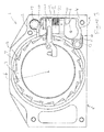
- a trigger mechanism 18 is provided to prevent contact between the pawl 2 and ratchet 3 until the pawl assembly 1 is positively triggered, for example by an acceleration sensor 42 or dwell mechanism 43 (shown in figure 8 ).
- the trigger mechanism 18 comprises a trigger finger 19 pivotably mounted to the pawl 2.
- a trip plate 20 (only shown in figures 1 and 2 and removed in figures 3 to 6 for clarity) is mounted co-axially with, but not connected to, the ratchet wheel 3.
- the trigger finger 19 is provided with a shoulder 21 which engages with an edge 22 of the trip plate 20, to prevent the pawl 2 from engaging with the ratchet 3.
- the trigger finger 19 is further provided with contact pads, which may be used to activate the trigger finger 19.
- a contact pad may comprise a polymeric screw having a rounded head, the screw received in a respective threaded bore of the pawl 2. The position of the screw with respect to the bore, and thus the pawl 2, may be adjusted so as to calibrate the point at which the acceleration sensor causes the trigger finger 19 to actuate, and allow the pawl 2 to engage with the ratchet 3
- the trigger finger 19 is provided with a torsional spring 23 between the trigger finger 19 and the pawl 2. This reduces the risk of inadvertent dislodgement of the trigger finger 19 from the trip plate 20, for example when the housing 5 is subject to a sudden force which is below that required to trip the acceleration sensor. Additionally, the spring 23 is used to cause the trigger finger 19 to re-engage with the edge 23 of the trip plate 20 when the pawl assembly 1 is re-set.
- the pawl 2 is held in a floating engagement with respect to the support structure 4.
- the floating engagement is afforded by the use of a torsional spring 13 between the pawl 2 and the support structure 4.
- the pawl 2 is substantially free to move in any direction in at least the plane parallel to the ratchet wheel 3 (i.e. perpendicular to the rotational axis 6 of the ratchet wheel 3). Accordingly, the pawl 2 as a whole may translate in any direction within the plane, and also rotate within the plane (about an axis perpendicular to the plane).
- Such a floating arrangement is not possible with prior art pawls, which pivot about a fixed point.
- the pawl 2 of the present invention is not fixed with respect to the support structure 4 but is able to float.
- Figure 4 shows the pawl assembly 1 immediately after having been triggered.
- the shoulder 21 has been dislodged from the edge 22 of the trip plate 20 and the biasing force (indicated by solid arrow 26) of the pawl driving spring 17 causes the pawl tip 10 to travel towards the ratchet wheel 3.
- the pawl 2 tends to pivot (indicated by grey arrow 27) about the axis of the bore 16.
- the tooth 7 Upon contact, the tooth 7 will apply a force, indicated by arrow 24, to the pawl 2, as indicated in figures 4 and 5 .
- the force 24 will be applied in a direction generally parallel to the tangent of the ratchet 3 at the point of contact.
- the torsional spring 13 will be depressed, causing the pawl 2 to move with the rotation of the ratchet 3.
- the force 24 imposed on the pawl 2 will cause the pawl 2 to move in a generally linear direction downwards (indicated by grey arrow 25).
- Arrow 24 is shown with hatching to denote that the pawl 2 is not subjected to the full reactionary force of the ratchet tooth 7, because some of that force is taken up by the torsion spring 13.
- the pawl driving spring 17 continues to impart a biasing force on the pawl 2, promoting full engagement of the pawl tip 10 with the teeth 7. Accordingly, if there was only marginal initial contact between the pawl tip 10 and the tooth 7, any frictional forces across the contact area will be at least partially counteracted by the resiliency of the torsional spring 13. In the prior art, any marginal contact may otherwise cause the tooth to shear or be damaged, or cause the pawl tip to skip from the tooth.
- the force 26 imparted by the pawl driving spring 17 may be greater than the surface friction between the pawl tip 10 and tooth 7 in cases of marginal contact, causing the pawl tip 10 to further engage with the tooth 7, increasing the contact area.
- This is possible due to the floating engagement of the pawl 2 with respect to the support structure 4. Without the floating engagement of the present invention, the frictional forces in the case of marginal contact would be too great and would not allow full engagement of the pawl with the tooth.
- the pawl assembly 1 is configured so as to allow a predetermined amount of movement of the pawl within the recess 9 in the housing 5. The greater the amount of floating movement allowed; the more likely the pawl 2 will be able to engage fully with the leading face 8 of a tooth 7. However, if the amount of floating movement allowed is too large, there will be an appreciable delay between the activation of the pawl 2 and the full locking of the ratchet 3.
- a pawl assembly 1 embodying the present invention is configured so as to reduce the likelihood of damage to either or both of the pawl tip 10 and ratchet teeth 7, whilst ensuring a reliable and fast acting ratchet and pawl system.
- the pawl tip 10 may still not be in full engagement with the leading face 8 of the tooth 7 by the time the pawl 2 has travelled to the limit of its floating movement (i.e. the end of a first phase).
- Embodiments of the present invention account for this by affording a secondary pivoting motion (a second phase) to urge the pawl 2 into full contact with the tooth 7 of the ratchet.
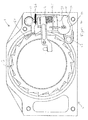
- the support structure 4 comprises an abutment portion 28.
- the abutment portion 28 comprises a profiled (e.g. raised) inner surface of the recess 9 of the housing 5.
- the base of the pawl comprises a substantially cylindrical portion 29 having a lug 30 extending therefrom.
- the aforementioned bore 16 - in which one leg 15 of the torsional spring 13 is received - is provided in the centre of the substantially cylindrical portion 29.
- the abutment portion 28 of the support structure 4 comprises a profiled surface having a cylindrical bearing portion 31 of substantially the same radius as the cylindrical portion 29 of the base 11 of the pawl 2.
- the profiled surface further comprises a step 32, which is operable to contact the lug 30 of the pawl.
- the profiled surface is therefore substantially of the same shape as the profile of the cylindrical portion 29 and lug 30 of the pawl.
- the pawl assembly 1 is configured such that as the pawl 2 approaches the abutment portion, contact is first made between the lug 30 and the step 28 , as shown in figure 5 .
- One particular benefit of the invention is that the full load 34 of the reactionary force of the ratchet tooth 7 is only imparted on the pawl 2 after the tip 10 of the pawl 2 is in full engagement with the ratchet tooth 7, thereby preventing tooth shear or tooth damage.
- the partial load 24 denoted in figures 4 and 5 when there is marginal contact, with the full load 34 denoted in figure 6 when there is full engagement with the pawl trip 11 and leading force 8 of tooth 7.
- This geometric configuration of the pawl assembly 1, more specifically the support structure 4, is such that the full load will not be transmitted when there is only marginal contact.
- the ratchet wheel may be a rack.
- the abutment portion may comprise a peg or protrusion, so long as it causes the pawl to rotate when the pawl contacts the abutment portion.
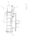
- the pawl assembly may be utilised in a reel assembly 40, as shown in Figure 7 , having a housing 5 and a spool 41, around which a webbing strap (not shown) may be stored.
- Figure 8 illustrates an exploded view of a reel assembly 40, including the pawl assembly 1.
- the reel assembly comprises an acceleration sensor 42 and a dwell mechanism 43.
Landscapes
- Engineering & Computer Science (AREA)
- Mechanical Engineering (AREA)
- Transmission Devices (AREA)
Applications Claiming Priority (1)
| Application Number | Priority Date | Filing Date | Title |
|---|---|---|---|
| GB0913723A GB2472433B (en) | 2009-08-06 | 2009-08-06 | A pawl assembly |
Publications (2)
| Publication Number | Publication Date |
|---|---|
| EP2284049A1 true EP2284049A1 (fr) | 2011-02-16 |
| EP2284049B1 EP2284049B1 (fr) | 2012-11-14 |
Family
ID=41129718
Family Applications (1)
| Application Number | Title | Priority Date | Filing Date |
|---|---|---|---|
| EP09167778A Not-in-force EP2284049B1 (fr) | 2009-08-06 | 2009-08-13 | Ensemble d'arrêtoir |
Country Status (3)
| Country | Link |
|---|---|
| US (1) | US8136752B2 (fr) |
| EP (1) | EP2284049B1 (fr) |
| GB (1) | GB2472433B (fr) |
Families Citing this family (1)
| Publication number | Priority date | Publication date | Assignee | Title |
|---|---|---|---|---|
| DE102011103113A1 (de) * | 2011-05-25 | 2012-11-29 | Trw Automotive Gmbh | Baugruppe für einen Gurtaufroller |
Citations (6)
| Publication number | Priority date | Publication date | Assignee | Title |
|---|---|---|---|---|
| US3667698A (en) * | 1971-01-22 | 1972-06-06 | Robert C Fisher | Locking seat belt retractor |
| DE2253671A1 (de) * | 1971-11-29 | 1973-06-07 | Svensson Gustav E W | Sicherungsvorrichtung fuer trommelwinden, insbesondere fahrzeugwindenvorrichtung |
| DE2346553A1 (de) * | 1972-09-20 | 1974-04-18 | Autoliv Ab | Beschleunigungsabhaengige sperrvorrichtung, insbesondere fuer sicherheitsgurte an fahrzeugen |
| US4085905A (en) | 1974-08-29 | 1978-04-25 | Oskar Lennart Lindbald | Blocking device preferably for reel-type safety belts for vehicles |
| US4905928A (en) * | 1988-05-20 | 1990-03-06 | Kabushiki Kaisha Tokai-Rika-Denki Seisakusho | Locking apparatus for webbing retractor |
| EP1992528A2 (fr) * | 2007-05-18 | 2008-11-19 | Delphi Korea Corporation | Rétracteur de ceinture de sécurité |
Family Cites Families (29)
| Publication number | Priority date | Publication date | Assignee | Title |
|---|---|---|---|---|
| US3108456A (en) | 1961-03-14 | 1963-10-29 | Rheinmetall Gmbh | Homokinetic universal joing for large angles of misalignment |
| US3711037A (en) | 1971-04-05 | 1973-01-16 | American Safety Equip | Dead zone mechanism for and inertia locking retractor |
| US4065905A (en) * | 1972-08-21 | 1978-01-03 | Lely Cornelis V D | Prefabricated building sections or room units and methods for the manufacture of such sections or units |
| US3838832A (en) | 1973-01-02 | 1974-10-01 | Irvin Industries Inc | Safety belt retractor locking device |
| JPS51135016A (en) * | 1975-05-17 | 1976-11-22 | Takata Kk | Acceleration-responsive retractor |
| US4108394A (en) | 1976-09-17 | 1978-08-22 | Tokai-Rika-Denki-Seisakusho | Seatbelt retractor for motor vehicles |
| US4135683A (en) * | 1977-07-21 | 1979-01-23 | Allied Chemical Corporation | Safety belt retractor having two reels in a common housing |
| IT1091369B (it) | 1977-12-02 | 1985-07-06 | Scudo Soc S R L | Arrotolatore per cinture di sicurezza per autoveicoli |
| DE2827409A1 (de) | 1978-06-22 | 1980-01-10 | Klippan Nv | Auf fahrzeugbeschleunigung ansprechende, justierbare sensorvorrichtung |
| US4241887A (en) * | 1979-09-21 | 1980-12-30 | General Motors Corporation | Winding prevention mechanism for seat belt retractor |
| JPS58139159U (ja) | 1982-03-12 | 1983-09-19 | 株式会社東海理化電機製作所 | ウエビング巻取装置 |
| DE3212992A1 (de) | 1982-04-07 | 1983-10-20 | Naamloze Vennootschap Klippan S.A., 3030 Heverlee | Gurtaufrollschnellsperrautomat |
| IN160515B (fr) | 1982-11-20 | 1987-07-18 | Britax Kolb Gmbh & Co | |
| GB8406493D0 (en) * | 1984-03-13 | 1984-04-18 | Britax Kolb Gmbh & Co | Safety belt emergency locking retractor |
| JPH0572612U (ja) | 1992-03-09 | 1993-10-05 | 株式会社東海理化電機製作所 | ウエビング巻取装置 |
| WO1996003295A1 (fr) | 1994-07-21 | 1996-02-08 | Alliedsignal Inc. | Retracteur de ceinture de securite et mecanisme de detection ameliore |
| US5636807A (en) | 1994-08-01 | 1997-06-10 | H. Koch & Sons Co., Inc. | Acceleration sensor having inertia weight responsive to accelerations in every direction |
| US5660444A (en) | 1995-12-28 | 1997-08-26 | Alliedsignal Inc. | Shoulder webbing retractor for a safety restraint system having a self-zeroing center of gravity assembly |
| US5950952A (en) | 1996-02-02 | 1999-09-14 | Kabushiki Kaisha Tokai-Rika-Denki-Seisakusho | Acceleration sensor apparatus for a vehicle |
| JP4163291B2 (ja) | 1998-07-28 | 2008-10-08 | 株式会社東海理化電機製作所 | 加速度センサ |
| DE19835672A1 (de) | 1998-08-06 | 2000-02-10 | Takata Europ Gmbh | Sicherheitsgurtvorrichtung mit Beschleunigungssensor |
| GB2347900A (en) * | 1999-03-15 | 2000-09-20 | Breed Automotive Tech | Seat Belt Retractor |
| GB9908976D0 (en) | 1999-04-21 | 1999-06-16 | Breed Automotive Tech | A seat belt retractor |
| DE20006314U1 (de) * | 2000-04-06 | 2000-08-17 | TRW Occupant Restraint Systems GmbH & Co. KG, 73553 Alfdorf | Trägheitssensor |
| JP2002234417A (ja) * | 2000-12-04 | 2002-08-20 | Takata Corp | シートベルト巻き取り装置 |
| JP4521798B2 (ja) * | 2001-01-22 | 2010-08-11 | タカタ株式会社 | シートベルト巻き取り装置 |
| GB0207030D0 (en) | 2002-03-25 | 2002-05-08 | Baker Martin Aircraft Co | Multi-axis "g" sensor |
| JP2006103678A (ja) | 2004-09-29 | 2006-04-20 | Trw Automotive Gmbh | 車輛乗員拘束システムを作動するためのセンサ |
| US7731118B2 (en) * | 2006-03-29 | 2010-06-08 | Martin-Baker Aircraft Co., Ltd. | Acceleration sensor |
-
2009
- 2009-08-06 GB GB0913723A patent/GB2472433B/en active Active
- 2009-08-13 EP EP09167778A patent/EP2284049B1/fr not_active Not-in-force
- 2009-08-18 US US12/543,029 patent/US8136752B2/en active Active
Patent Citations (6)
| Publication number | Priority date | Publication date | Assignee | Title |
|---|---|---|---|---|
| US3667698A (en) * | 1971-01-22 | 1972-06-06 | Robert C Fisher | Locking seat belt retractor |
| DE2253671A1 (de) * | 1971-11-29 | 1973-06-07 | Svensson Gustav E W | Sicherungsvorrichtung fuer trommelwinden, insbesondere fahrzeugwindenvorrichtung |
| DE2346553A1 (de) * | 1972-09-20 | 1974-04-18 | Autoliv Ab | Beschleunigungsabhaengige sperrvorrichtung, insbesondere fuer sicherheitsgurte an fahrzeugen |
| US4085905A (en) | 1974-08-29 | 1978-04-25 | Oskar Lennart Lindbald | Blocking device preferably for reel-type safety belts for vehicles |
| US4905928A (en) * | 1988-05-20 | 1990-03-06 | Kabushiki Kaisha Tokai-Rika-Denki Seisakusho | Locking apparatus for webbing retractor |
| EP1992528A2 (fr) * | 2007-05-18 | 2008-11-19 | Delphi Korea Corporation | Rétracteur de ceinture de sécurité |
Also Published As
| Publication number | Publication date |
|---|---|
| GB2472433B (en) | 2011-06-29 |
| US20110031342A1 (en) | 2011-02-10 |
| US8136752B2 (en) | 2012-03-20 |
| GB0913723D0 (en) | 2009-09-16 |
| EP2284049B1 (fr) | 2012-11-14 |
| GB2472433A (en) | 2011-02-09 |
Similar Documents
| Publication | Publication Date | Title |
|---|---|---|
| EP1902911B1 (fr) | Dispositif de rétracteur de sangle | |
| EP1295764B1 (fr) | Rétracteur de ceinture de sécurité | |
| US7410114B2 (en) | Compact dual-level load limiting seat belt retractor | |
| US8777269B2 (en) | Self-locking belt retractor | |
| CN114340960B (zh) | 带电动的锁止装置的安全带卷收器 | |
| US4729523A (en) | Locking mechanism for webbing retractor | |
| JP5907555B2 (ja) | トランスミッションのパーキングブレーキ装置 | |
| EP3851338A1 (fr) | Enrouleur de ceinture de sécurité et ensemble ceinture de sécurité | |
| US7731118B2 (en) | Acceleration sensor | |
| AU605796B2 (en) | Sensing and locking device for a safety belt system | |
| EP2284049B1 (fr) | Ensemble d'arrêtoir | |
| US4907820A (en) | Belt retractor | |
| US4508289A (en) | Roll-up device for safety belts | |
| SU1489579A3 (ru) | Автоматически заклинивающее устройство для системы ремней безопасности автомобиля | |
| CN102639368B (zh) | 自锁式安全带伸缩器 | |
| KR100455637B1 (ko) | 좌석 벨트 수축기 | |
| US5669573A (en) | Belt retractor | |
| US20140239110A1 (en) | Webbing take-up device | |
| US4186895A (en) | Safety belt retractor | |
| US5390874A (en) | Vehicle sensitive retractor | |
| FR2483788A1 (fr) | Enrouleur de ceinture de securite avec mecanisme de blocage d'urgence pour un vehicule, notamment un vehicule automobile | |
| US5301894A (en) | Webbing retractor | |
| KR20210129217A (ko) | 보조 스풀 로킹 시스템을 갖는 시트 벨트 리트랙터 | |
| US4166592A (en) | Seat belt retractor | |
| EP1552992B1 (fr) | Rétracteur de ceinture de sécurité |
Legal Events
| Date | Code | Title | Description |
|---|---|---|---|
| PUAI | Public reference made under article 153(3) epc to a published international application that has entered the european phase |
Free format text: ORIGINAL CODE: 0009012 |
|
| AK | Designated contracting states |
Kind code of ref document: A1 Designated state(s): AT BE BG CH CY CZ DE DK EE ES FI FR GB GR HR HU IE IS IT LI LT LU LV MC MK MT NL NO PL PT RO SE SI SK SM TR |
|
| AX | Request for extension of the european patent |
Extension state: AL BA RS |
|
| 17P | Request for examination filed |
Effective date: 20110512 |
|
| GRAP | Despatch of communication of intention to grant a patent |
Free format text: ORIGINAL CODE: EPIDOSNIGR1 |
|
| GRAS | Grant fee paid |
Free format text: ORIGINAL CODE: EPIDOSNIGR3 |
|
| GRAA | (expected) grant |
Free format text: ORIGINAL CODE: 0009210 |
|
| RBV | Designated contracting states (corrected) |
Designated state(s): AT BE BG CH CY CZ DE DK EE ES FI FR GR HR HU IE IS IT LI LT LU LV MC MK MT NL NO PL PT RO SE SI SK SM TR |
|
| AK | Designated contracting states |
Kind code of ref document: B1 Designated state(s): AT BE BG CH CY CZ DE DK EE ES FI FR GR HR HU IE IS IT LI LT LU LV MC MK MT NL NO PL PT RO SE SI SK SM TR |
|
| REG | Reference to a national code |
Ref country code: AT Ref legal event code: REF Ref document number: 583791 Country of ref document: AT Kind code of ref document: T Effective date: 20121115 Ref country code: CH Ref legal event code: EP |
|
| REG | Reference to a national code |
Ref country code: IE Ref legal event code: FG4D |
|
| REG | Reference to a national code |
Ref country code: DE Ref legal event code: R096 Ref document number: 602009011138 Country of ref document: DE Effective date: 20130110 |
|
| REG | Reference to a national code |
Ref country code: NL Ref legal event code: VDEP Effective date: 20121114 |
|
| REG | Reference to a national code |
Ref country code: AT Ref legal event code: MK05 Ref document number: 583791 Country of ref document: AT Kind code of ref document: T Effective date: 20121114 |
|
| REG | Reference to a national code |
Ref country code: LT Ref legal event code: MG4D |
|
| PG25 | Lapsed in a contracting state [announced via postgrant information from national office to epo] |
Ref country code: HR Free format text: LAPSE BECAUSE OF FAILURE TO SUBMIT A TRANSLATION OF THE DESCRIPTION OR TO PAY THE FEE WITHIN THE PRESCRIBED TIME-LIMIT Effective date: 20121114 Ref country code: FI Free format text: LAPSE BECAUSE OF FAILURE TO SUBMIT A TRANSLATION OF THE DESCRIPTION OR TO PAY THE FEE WITHIN THE PRESCRIBED TIME-LIMIT Effective date: 20121114 Ref country code: SE Free format text: LAPSE BECAUSE OF FAILURE TO SUBMIT A TRANSLATION OF THE DESCRIPTION OR TO PAY THE FEE WITHIN THE PRESCRIBED TIME-LIMIT Effective date: 20121114 Ref country code: ES Free format text: LAPSE BECAUSE OF FAILURE TO SUBMIT A TRANSLATION OF THE DESCRIPTION OR TO PAY THE FEE WITHIN THE PRESCRIBED TIME-LIMIT Effective date: 20130225 Ref country code: NO Free format text: LAPSE BECAUSE OF FAILURE TO SUBMIT A TRANSLATION OF THE DESCRIPTION OR TO PAY THE FEE WITHIN THE PRESCRIBED TIME-LIMIT Effective date: 20130214 Ref country code: LT Free format text: LAPSE BECAUSE OF FAILURE TO SUBMIT A TRANSLATION OF THE DESCRIPTION OR TO PAY THE FEE WITHIN THE PRESCRIBED TIME-LIMIT Effective date: 20121114 |
|
| PG25 | Lapsed in a contracting state [announced via postgrant information from national office to epo] |
Ref country code: BE Free format text: LAPSE BECAUSE OF FAILURE TO SUBMIT A TRANSLATION OF THE DESCRIPTION OR TO PAY THE FEE WITHIN THE PRESCRIBED TIME-LIMIT Effective date: 20121114 Ref country code: LV Free format text: LAPSE BECAUSE OF FAILURE TO SUBMIT A TRANSLATION OF THE DESCRIPTION OR TO PAY THE FEE WITHIN THE PRESCRIBED TIME-LIMIT Effective date: 20121114 Ref country code: GR Free format text: LAPSE BECAUSE OF FAILURE TO SUBMIT A TRANSLATION OF THE DESCRIPTION OR TO PAY THE FEE WITHIN THE PRESCRIBED TIME-LIMIT Effective date: 20130215 Ref country code: SI Free format text: LAPSE BECAUSE OF FAILURE TO SUBMIT A TRANSLATION OF THE DESCRIPTION OR TO PAY THE FEE WITHIN THE PRESCRIBED TIME-LIMIT Effective date: 20121114 Ref country code: PT Free format text: LAPSE BECAUSE OF FAILURE TO SUBMIT A TRANSLATION OF THE DESCRIPTION OR TO PAY THE FEE WITHIN THE PRESCRIBED TIME-LIMIT Effective date: 20130314 Ref country code: PL Free format text: LAPSE BECAUSE OF FAILURE TO SUBMIT A TRANSLATION OF THE DESCRIPTION OR TO PAY THE FEE WITHIN THE PRESCRIBED TIME-LIMIT Effective date: 20121114 |
|
| PG25 | Lapsed in a contracting state [announced via postgrant information from national office to epo] |
Ref country code: AT Free format text: LAPSE BECAUSE OF FAILURE TO SUBMIT A TRANSLATION OF THE DESCRIPTION OR TO PAY THE FEE WITHIN THE PRESCRIBED TIME-LIMIT Effective date: 20121114 |
|
| PG25 | Lapsed in a contracting state [announced via postgrant information from national office to epo] |
Ref country code: BG Free format text: LAPSE BECAUSE OF FAILURE TO SUBMIT A TRANSLATION OF THE DESCRIPTION OR TO PAY THE FEE WITHIN THE PRESCRIBED TIME-LIMIT Effective date: 20130214 Ref country code: DK Free format text: LAPSE BECAUSE OF FAILURE TO SUBMIT A TRANSLATION OF THE DESCRIPTION OR TO PAY THE FEE WITHIN THE PRESCRIBED TIME-LIMIT Effective date: 20121114 Ref country code: EE Free format text: LAPSE BECAUSE OF FAILURE TO SUBMIT A TRANSLATION OF THE DESCRIPTION OR TO PAY THE FEE WITHIN THE PRESCRIBED TIME-LIMIT Effective date: 20121114 Ref country code: SK Free format text: LAPSE BECAUSE OF FAILURE TO SUBMIT A TRANSLATION OF THE DESCRIPTION OR TO PAY THE FEE WITHIN THE PRESCRIBED TIME-LIMIT Effective date: 20121114 Ref country code: CZ Free format text: LAPSE BECAUSE OF FAILURE TO SUBMIT A TRANSLATION OF THE DESCRIPTION OR TO PAY THE FEE WITHIN THE PRESCRIBED TIME-LIMIT Effective date: 20121114 |
|
| PG25 | Lapsed in a contracting state [announced via postgrant information from national office to epo] |
Ref country code: NL Free format text: LAPSE BECAUSE OF FAILURE TO SUBMIT A TRANSLATION OF THE DESCRIPTION OR TO PAY THE FEE WITHIN THE PRESCRIBED TIME-LIMIT Effective date: 20121114 Ref country code: RO Free format text: LAPSE BECAUSE OF FAILURE TO SUBMIT A TRANSLATION OF THE DESCRIPTION OR TO PAY THE FEE WITHIN THE PRESCRIBED TIME-LIMIT Effective date: 20121114 Ref country code: IT Free format text: LAPSE BECAUSE OF FAILURE TO SUBMIT A TRANSLATION OF THE DESCRIPTION OR TO PAY THE FEE WITHIN THE PRESCRIBED TIME-LIMIT Effective date: 20121114 |
|
| PLBE | No opposition filed within time limit |
Free format text: ORIGINAL CODE: 0009261 |
|
| STAA | Information on the status of an ep patent application or granted ep patent |
Free format text: STATUS: NO OPPOSITION FILED WITHIN TIME LIMIT |
|
| 26N | No opposition filed |
Effective date: 20130815 |
|
| PG25 | Lapsed in a contracting state [announced via postgrant information from national office to epo] |
Ref country code: CY Free format text: LAPSE BECAUSE OF FAILURE TO SUBMIT A TRANSLATION OF THE DESCRIPTION OR TO PAY THE FEE WITHIN THE PRESCRIBED TIME-LIMIT Effective date: 20121114 |
|
| REG | Reference to a national code |
Ref country code: DE Ref legal event code: R097 Ref document number: 602009011138 Country of ref document: DE Effective date: 20130815 |
|
| REG | Reference to a national code |
Ref country code: CH Ref legal event code: PL |
|
| PG25 | Lapsed in a contracting state [announced via postgrant information from national office to epo] |
Ref country code: MC Free format text: LAPSE BECAUSE OF FAILURE TO SUBMIT A TRANSLATION OF THE DESCRIPTION OR TO PAY THE FEE WITHIN THE PRESCRIBED TIME-LIMIT Effective date: 20121114 Ref country code: CH Free format text: LAPSE BECAUSE OF NON-PAYMENT OF DUE FEES Effective date: 20130831 Ref country code: LI Free format text: LAPSE BECAUSE OF NON-PAYMENT OF DUE FEES Effective date: 20130831 |
|
| PG25 | Lapsed in a contracting state [announced via postgrant information from national office to epo] |
Ref country code: SM Free format text: LAPSE BECAUSE OF FAILURE TO SUBMIT A TRANSLATION OF THE DESCRIPTION OR TO PAY THE FEE WITHIN THE PRESCRIBED TIME-LIMIT Effective date: 20121114 |
|
| PG25 | Lapsed in a contracting state [announced via postgrant information from national office to epo] |
Ref country code: MT Free format text: LAPSE BECAUSE OF FAILURE TO SUBMIT A TRANSLATION OF THE DESCRIPTION OR TO PAY THE FEE WITHIN THE PRESCRIBED TIME-LIMIT Effective date: 20121114 Ref country code: TR Free format text: LAPSE BECAUSE OF FAILURE TO SUBMIT A TRANSLATION OF THE DESCRIPTION OR TO PAY THE FEE WITHIN THE PRESCRIBED TIME-LIMIT Effective date: 20121114 |
|
| PG25 | Lapsed in a contracting state [announced via postgrant information from national office to epo] |
Ref country code: MK Free format text: LAPSE BECAUSE OF FAILURE TO SUBMIT A TRANSLATION OF THE DESCRIPTION OR TO PAY THE FEE WITHIN THE PRESCRIBED TIME-LIMIT Effective date: 20121114 Ref country code: LU Free format text: LAPSE BECAUSE OF NON-PAYMENT OF DUE FEES Effective date: 20130813 Ref country code: HU Free format text: LAPSE BECAUSE OF FAILURE TO SUBMIT A TRANSLATION OF THE DESCRIPTION OR TO PAY THE FEE WITHIN THE PRESCRIBED TIME-LIMIT; INVALID AB INITIO Effective date: 20090813 |
|
| REG | Reference to a national code |
Ref country code: FR Ref legal event code: PLFP Year of fee payment: 8 |
|
| PG25 | Lapsed in a contracting state [announced via postgrant information from national office to epo] |
Ref country code: IS Free format text: LAPSE BECAUSE OF FAILURE TO SUBMIT A TRANSLATION OF THE DESCRIPTION OR TO PAY THE FEE WITHIN THE PRESCRIBED TIME-LIMIT Effective date: 20121114 |
|
| REG | Reference to a national code |
Ref country code: FR Ref legal event code: PLFP Year of fee payment: 9 |
|
| PGFP | Annual fee paid to national office [announced via postgrant information from national office to epo] |
Ref country code: IE Payment date: 20170907 Year of fee payment: 9 |
|
| REG | Reference to a national code |
Ref country code: FR Ref legal event code: PLFP Year of fee payment: 10 |
|
| REG | Reference to a national code |
Ref country code: IE Ref legal event code: MM4A |
|
| PG25 | Lapsed in a contracting state [announced via postgrant information from national office to epo] |
Ref country code: IE Free format text: LAPSE BECAUSE OF NON-PAYMENT OF DUE FEES Effective date: 20180813 |
|
| PGFP | Annual fee paid to national office [announced via postgrant information from national office to epo] |
Ref country code: DE Payment date: 20190730 Year of fee payment: 11 Ref country code: FR Payment date: 20190711 Year of fee payment: 11 |
|
| REG | Reference to a national code |
Ref country code: DE Ref legal event code: R119 Ref document number: 602009011138 Country of ref document: DE |
|
| PG25 | Lapsed in a contracting state [announced via postgrant information from national office to epo] |
Ref country code: DE Free format text: LAPSE BECAUSE OF NON-PAYMENT OF DUE FEES Effective date: 20210302 Ref country code: FR Free format text: LAPSE BECAUSE OF NON-PAYMENT OF DUE FEES Effective date: 20200831 |
|
| P01 | Opt-out of the competence of the unified patent court (upc) registered |
Effective date: 20230609 |
|
| P02 | Opt-out of the competence of the unified patent court (upc) changed |
Effective date: 20230617 |