EP2286010B1 - Vorrichtung zum anspannen eines dreherfadens einer drehervorrichtung für eine webmaschine - Google Patents
Vorrichtung zum anspannen eines dreherfadens einer drehervorrichtung für eine webmaschine Download PDFInfo
- Publication number
- EP2286010B1 EP2286010B1 EP09733942A EP09733942A EP2286010B1 EP 2286010 B1 EP2286010 B1 EP 2286010B1 EP 09733942 A EP09733942 A EP 09733942A EP 09733942 A EP09733942 A EP 09733942A EP 2286010 B1 EP2286010 B1 EP 2286010B1
- Authority
- EP
- European Patent Office
- Prior art keywords
- thread
- leno
- bending point
- doup heddle
- resilient element
- Prior art date
- Legal status (The legal status is an assumption and is not a legal conclusion. Google has not performed a legal analysis and makes no representation as to the accuracy of the status listed.)
- Not-in-force
Links
Images


Classifications
-
- D—TEXTILES; PAPER
- D03—WEAVING
- D03C—SHEDDING MECHANISMS; PATTERN CARDS OR CHAINS; PUNCHING OF CARDS; DESIGNING PATTERNS
- D03C7/00—Leno or similar shedding mechanisms
-
- B—PERFORMING OPERATIONS; TRANSPORTING
- B65—CONVEYING; PACKING; STORING; HANDLING THIN OR FILAMENTARY MATERIAL
- B65H—HANDLING THIN OR FILAMENTARY MATERIAL, e.g. SHEETS, WEBS, CABLES
- B65H59/00—Adjusting or controlling tension in filamentary material, e.g. for preventing snarling; Applications of tension indicators
- B65H59/10—Adjusting or controlling tension in filamentary material, e.g. for preventing snarling; Applications of tension indicators by devices acting on running material and not associated with supply or take-up devices
- B65H59/36—Floating elements compensating for irregularities in supply or take-up of material
-
- D—TEXTILES; PAPER
- D03—WEAVING
- D03C—SHEDDING MECHANISMS; PATTERN CARDS OR CHAINS; PUNCHING OF CARDS; DESIGNING PATTERNS
- D03C7/00—Leno or similar shedding mechanisms
- D03C7/02—Gauze healds
-
- B—PERFORMING OPERATIONS; TRANSPORTING
- B65—CONVEYING; PACKING; STORING; HANDLING THIN OR FILAMENTARY MATERIAL
- B65H—HANDLING THIN OR FILAMENTARY MATERIAL, e.g. SHEETS, WEBS, CABLES
- B65H2701/00—Handled material; Storage means
- B65H2701/30—Handled filamentary material
- B65H2701/31—Textiles threads or artificial strands of filaments
-
- B—PERFORMING OPERATIONS; TRANSPORTING
- B65—CONVEYING; PACKING; STORING; HANDLING THIN OR FILAMENTARY MATERIAL
- B65H—HANDLING THIN OR FILAMENTARY MATERIAL, e.g. SHEETS, WEBS, CABLES
- B65H2701/00—Handled material; Storage means
- B65H2701/30—Handled filamentary material
- B65H2701/38—Thread sheet, e.g. sheet of parallel yarns or wires
Definitions
- the invention relates to a device for the tensioning of a leno thread for a doup heddle device for a weaving machine according to the preamble of claim 1 and to a weaving machine with a device according to the preamble of claim 7.
- a doup heddle device also known as a leno heddle device
- a doup heddle device in order to form a leno weave structure using what are known as fixed and alternating leno threads together with weft threads.
- two leno threads are brought each from a thread supply, via a thread compensator, a fixedly positioned thread guide, a thread stop motion and a thread holding-down member to a doup heddle device consisting of two lifting heddles which interact with a doup heddle.
- a doup heddle device of this type is unable to accommodate the difference in length in the leno threads resulting from the upward and downward movement. This is also accompanied by undesirably high variations in the tension in the leno threads. This also has the consequence that no good weaving shed can be formed with the leno threads and that this can result in weaving faults. This occurs particularly at high weaving speeds.
- Doup heddle devices of this type are furthermore also known from US 2647541 , which is considered to be the closest prior art, US 2389258 , EP 1036228A1 and BE 1012453 .
- This allows to compensate for tension variations in the leno threads.
- a problem arises when a compensation of this type is provided for the alternating leno thread which forms the bottom shed.
- the bottom shed is then no longer absolutely defined; that is to say, the alternating leno thread has no fixed vertical position, as a result of which there is the risk that the alternating leno thread which forms the bottom shed will come into contact with the weft thread or with an insertion element such as a gripper, a gripper band or the like during insertion.
- the weft thread or the alternating leno thread can become disturbed or damaged, and this can cause a fault in the woven material or the interrupting of the weaving process.
- the bending point for the alternating leno thread can be chosen to be sufficiently low in order not to disrupt the weft thread or an insertion element.
- this increases the requirements for the compensation, since greater length has to be compensated for, leading to greater movements of the compensation element and greater tension variations. A too low bottom shed in the lowest position can then again cause less efficient binding of the weft thread in proximity to the edge of the woven material.
- An object of the invention is a device of the aforementioned type which is intended to be applied together with a doup heddle device for a weaving machine which allows a well-defined bottom shed to be set and which continues to sufficiently compensate for differences in tension in the leno threads.
- an aforementioned device for the tensioning of a leno thread which device can be positioned in proximity to a doup heddle device and comprises for at least one leno thread a resiliently mounted thread guide which forms a bending point for the leno thread, this object is achieved in that the device also comprises a fixedly mountable thread guide as defined in claim 1.
- the bending point of the fixedly mountable thread guide forms in use the last bending point of the leno thread before the doup heddle device.
- the device according to the invention comprises a resiliently mounted thread guide which is supported by a resilient element.
- the resilient element consists of a resilient material, such as spring steel or synthetic material.
- the resilient element can be embodied as a leaf spring, a spring wire, a spiral spring or the like. This allows a simple construction of the device according to the invention.
- the holder for the fixedly mountable thread guide and the resiliently mounted thread guide can be fastened for example to a warp stop motion. This allows the device according to the invention to be fastened in a simple manner to an existing weaving machine.
- the invention further includes a weaving machine with a device for the tensioning of a leno thread according to the invention which can be positioned in proximity to a doup heddle device.
- the thread guide which is fixedly positioned in proximity to the doup heddle device, of the aforementioned device allows a desired weaving shed to be formed, while the resiliently mounted thread guide allows compensation to be provided for the difference in length or for the tension in the leno threads.
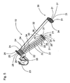
- two leno threads 2 and 3 are each brought from a thread supply, such as a bobbin 4 or 5, via a thread compensator 6 or 7, a fixedly positioned thread guide 8, a warp stop motion 9, and a device 10 according to the invention, to a doup heddle device 11.
- the doup heddle device 11 can consist, as is known from DE 3818680 C1 , of two lifting heddles 12 and 13 which can interact with a doup heddle 14, whereby each lifting heddle 12, 13 can lift the doup heddle 14.
- Also represented schematically are a warp beam 15 with warp threads 16, shed formation devices 17, a reed 18, and a cloth beam 19.
- the leno thread 2, which is guided through the doup heddle 14, is also referred to as the fixed leno thread
- the leno thread 3 which is guided around the doup heddle 14 and between an associated lifting heddle 12, 13, is also referred to as the alternating leno thread or alternating thread.
- the weaving machine as represented in figure 2 shows a doup heddle device 11 and a device 10 according to the invention which is positioned in proximity to the doup heddle device 11.
- the device 10 comprises, as represented in greater detail in figures 2 to 4 , for each leno thread 2, 3 a resiliently mounted thread guide 20 which forms a bending point 21 for a leno thread 2, 3.
- the thread guide 20 comprises a thread guide element which forms a bending point 21 for a leno thread 2, 3 and is resiliently mounted by means of a resilient element 22 to which the bending point 21 is attached.
- the resiliently mounted thread guide 20 is supported by the resilient element 22.
- the represented resilient element 22 is embodied as a leaf spring.
- the resilient element 22 can be made of spring steel, a synthetic material or another elastic material.
- the synthetic material used can be a polymer, a fiber-reinforced polymer, a glass fiber composite or any other known synthetic material having resilient properties.
- the use of synthetic material can be advantageous, as synthetic material usually also displays damping properties.
- the resilient element 22 can also be embodied as a spring wire made of elastic material.
- the resilient element 22 is attached to a holder 23 using fastening elements 24, for example a screw connection.
- the resilient element 22 can be attached to a holder by means of a glue connection or snap connection, or be made in one piece with a holder.
- a thread eye 25 is also arranged to guide a leno thread 2, 3 in proximity to the warp stop motion. This thread guide 25 can for example be embodied in a similar manner to the first bending point 21.
- the holder 23 is arranged in proximity to the warp stop motion 9.
- the holder 23 can for example be fastened to a transverse support 35 of the warp stop motion 9, while the warp stop motion 9 can be fastened to the frame of the weaving machine. It is clear that the holder 23 can also be fastened to the frame of the weaving machine directly or in a different manner.
- the device 10 according to the invention is located in this case in the warp direction between the warp stop motion 9 and the doup heddle device 11.
- the thread eyes 25 can be omitted and the leno threads 2, 3 can be guided for example on a transverse support 35 of the warp stop motion 9 to which the holder 23 is for example attached.
- the embodiment of the device 10 according to the invention as represented in figures 2 to 4 comprises a fixedly mountable thread guide 30 which forms a bending point 31 for a leno thread 2, 3.
- the bending point 31 is fixedly mounted.
- the thread guide 30 is attached to an arm 32 which is fastened to a holder 23 by means of fastening elements 33, such as a screw connection or a glue connection.
- the bending point 31 is in the represented embodiment embodied as a thread separator which was fastened to the arm 32 by means of fastening elements 34.
- the thread separator as represented in figures 3 and 4 can for example be made of ceramic, or be provided with a wear-resistant layer and consist of four thread guides positioned next to one another.
- the device 10 comprises four separately, resiliently mounted thread guides 20 and four fixedly mounted thread guides 30 for associated leno threads.
- Figure 4 shows that a leno thread 2 is guided through a set of thread guides 20, 30 and a leno thread 3 through another set of thread guides 20, 30.
- two other leno threads can also be guided in order to keep them tensioned.
- a device 10 can, as represented in figure 4 , guide four leno threads and keep them tensioned. It is clear that the represented device 10 can interact with one, two, three or four leno threads.
- the bending point 31 can also be embodied as a simple shaft or with the aid of single thread eyes which, if appropriate on a fastening plate, are fastened to an arm.
- the holder and/or the arm and/or the bending point 31 can be made in one piece.
- the thread guide 30, which forms a bending point 31 which is mounted fixedly and which in use is positioned in proximity to the doup heddle device 11, allows a clearly defined weaving shed 36 to be formed with the leno threads 2, 3, irrespective of the compensating action of the resiliently mounted bending point 21.
- the weaving shed 36 formed is defined by the position of the lowest leno threads 3 which define what is known as a bottom shed 37 and by the position of the uppermost leno threads 2 which define what is known as a top shed 38.
- the position of the bending point 31 defines in this case the position of the bottom shed, while the position of the thread eye of the doup heddle 14 defines the position of the top shed.
- the bending point 31 of the thread guide 30 forms in use the last bending point of the leno threads 2, 3 before the doup heddle device 11, the position of this bending point 31 defines in most doup heddle devices 11 the location of the bottom shed of the leno threads 2 and 3.
- the term "before” refers to a place in the direction of movement of the leno threads just before the doup heddle device 11. This means that no bending point remains present for a leno thread 2 or 3 between the bending point 31 of the thread guide 30 and the doup heddle device 11.
- the bending point 21, which is mounted resiliently is positioned in proximity to the fixedly mounted bending point 31, the differences in tension in the leno threads 2, 3 are sufficiently compensated for.
- the positioning of the bending points 31 allows slight bending around each bending point 31, as a result of which the friction between a bending point 31 and a leno thread 2, 3 is low.
- This length compensation at the level of the device 10 according to the invention is advantageous, as the device 10 according to the invention is positioned in proximity to the doup heddle device 11.
- the bending point 21 represented in figure 5 for a leno thread is formed by a thread guide element in the form of a thread eye which is attached to a resilient element 22.
- This attaching can for example be carried out by folding back the resilient element 22, which is embodied as a leaf spring, and providing therein an opening wherein, if appropriate, it is possible to attach an insert 39 which is made of ceramic material and forms the thread guide element.
- a thread eye is for example made of ceramic material and is attached to the resilient element 22, for example by means of a screw or glue connection.
- Figures 6 and 7 represent a variant embodiment of the device 10 which is not according to the invention. Similar components to those in the embodiment represented in figures 2 to 5 are denoted by the same reference numerals.
- the device 10 also comprises a bending point 21 which is resiliently mounted and a bending point 31 which is fixedly mounted.
- the bending point 31 is represented likewise as in the embodiment of figures 2 to 5 and is formed by a thread separator which is fastened to an arm 32 by means of fastening elements 34. This arm 32 is in turn fastened to the holder 23 by means of fastening elements 33.
- the bending point 21, which is resiliently mounted is embodied as a thread eye which is attached, for example by means of a glue connection, to a resilient element 22 which in this embodiment is embodied as a spiral spring.
- This resilient element is in turn fastened to an L-shaped holder 26, on which an arm 27 is fastened to a slot 29 of the arm 32 for the fixedly mounted thread guide 30 by means of fastening elements 28, for example a screwed connection.
- the bending points 21, 31 do not necessarily have to consist of a thread eye or thread separator, but can take any shape allowing the bending of a leno thread 2, 3.
- the resilient element 22 does not necessarily have to have in the tensionless state a substantially straight shape as represented in figure 3 , but can for example have a somewhat curved shape or if appropriate be embodied in a substantially L-shaped manner.
- the device 10 is applied as a thread holding-down member; this means that the leno threads 2 and 3 are held down around the bending points 31.
- the device according to the invention can also be positioned mirror-symmetrically with respect to the warp thread plane 16 in order to hold up in this way the leno threads and to act as a thread holding-up member.
- the doup heddle device should also be positioned mirror-symmetrically with respect to the warp thread plane 16.
- the operation of a device 10 according to the invention remains the same, irrespective of whether the device is applied as a thread holding-down member or as a thread holding-up member.
- the bottom shed and top shed should then be applied in an appropriate manner.
- a device 10 according to the invention can then interact with respectively two, four, six, eight or more leno threads.
- two, four, six, eight or more thread guides 20, 30 can be attached to the same or to separate holders.
- at least two devices 10 according to the invention which are for example each attached to a side of the weaving shed formed by the warp threads, are attached to a weaving machine according to the invention.
Landscapes
- Engineering & Computer Science (AREA)
- Textile Engineering (AREA)
- Looms (AREA)
Claims (7)
- Vorrichtung zum Spannen eines Dreherfadens (2, 3) für eine Drehervorrichtung (11) für eine Webmaschine, die in der Nähe der Drehervorrichtung (11) positioniert werden kann, wobei die Vorrichtung (10) einen Fadenführer (20) für mindestens einen Dreherfaden (2, 3) umfasst, der eine Biegestelle (21) für den Dreherfaden (2, 3) bildet, wobei der Fadenführer (20) mittels eines elastischen Elements (22) elastisch montiert ist, das elastische Element (22) auf einer Halterung (23) angebracht ist, und wobei die Vorrichtung (10) auch eine fest montierte Fadenführung (30) umfasst, die eine Biegestelle (31) für den Dreherfaden (2, 3) bildet, dadurch gekennzeichnet dass die fest montierte Fadenführung (30) auf einem Arm (32) angebracht ist, der auf der Halterung befestigt ist zum Positionieren der fest montierten Fadenführung (30) im Gebrauch in der Nähe der Drehervorrichtung (11), so dass der Fadenführer (30) im Gebrauch die letzte Biegestelle für die Dreherfäden (2, 3) vor der Drehervorrichtung (11) bildet.
- Vorrichtung nach Anspruch 1, dadurch gekennzeichnet, dass das elastische Element (22) aus einem elastischen Material, wie Federstahl oder aus einem synthetischen Material besteht.
- Vorrichtung nach Anspruch 2, dadurch gekennzeichnet, dass das elastische Element (22) als Blattfeder ausgebildet ist.
- Vorrichtung nach Anspruch 2, dadurch gekennzeichnet, dass das elastische Element (22) als Drahtfeder ausgebildet ist.
- Vorrichtung nach Anspruch 2, dadurch gekennzeichnet, dass das elastische Element (22) als Spiralfeder ausgebildet ist.
- Vorrichtung nach Anspruch 1, dadurch gekennzeichnet, dass die Halterung (23) auf einem Kettfadenwächter (9) befestigt werden kann.
- Webmaschine mit einer Vorrichtung zum Spannen eines Dreherfadens (2, 3) für eine Drehervorrichtung (11), dadurch gekennzeichnet, dass die Webmaschine eine Vorrichtung (10) nach einem der Ansprüche 1 bis 6 enthält, die in der Nähe eines Drehervorrichtung (11) positioniert ist.
Applications Claiming Priority (2)
| Application Number | Priority Date | Filing Date | Title |
|---|---|---|---|
| BE2008/0237A BE1018102A3 (nl) | 2008-04-21 | 2008-04-21 | Inrichting voor het spannen van een leno-draad voor een broekhevelinrichting voor een weefmachine. |
| PCT/EP2009/002722 WO2009129950A1 (en) | 2008-04-21 | 2009-04-14 | Device for the tensioning of a leno thread for a doup heddle device for a weaving machine |
Publications (2)
| Publication Number | Publication Date |
|---|---|
| EP2286010A1 EP2286010A1 (de) | 2011-02-23 |
| EP2286010B1 true EP2286010B1 (de) | 2013-01-30 |
Family
ID=40377237
Family Applications (1)
| Application Number | Title | Priority Date | Filing Date |
|---|---|---|---|
| EP09733942A Not-in-force EP2286010B1 (de) | 2008-04-21 | 2009-04-14 | Vorrichtung zum anspannen eines dreherfadens einer drehervorrichtung für eine webmaschine |
Country Status (4)
| Country | Link |
|---|---|
| EP (1) | EP2286010B1 (de) |
| CN (1) | CN102084047B (de) |
| BE (1) | BE1018102A3 (de) |
| WO (1) | WO2009129950A1 (de) |
Families Citing this family (4)
| Publication number | Priority date | Publication date | Assignee | Title |
|---|---|---|---|---|
| CN102277665A (zh) * | 2011-07-20 | 2011-12-14 | 海宁市建利纺织有限公司 | 化纤丝张力缓冲装置 |
| CN103061012B (zh) * | 2012-12-30 | 2014-07-16 | 青岛纺联控股集团有限公司 | 宽幅布机开幅装置 |
| CN105821554B (zh) * | 2015-05-08 | 2017-05-10 | 湖州永昌丝绸有限公司 | 一种用于剑杆织机的绞综织造工艺及装置 |
| CN114575014A (zh) * | 2022-03-14 | 2022-06-03 | 苏州市锦达丝绸有限公司 | 一种五经花罗绞经开口张力调节装置 |
Family Cites Families (5)
| Publication number | Priority date | Publication date | Assignee | Title |
|---|---|---|---|---|
| US2647541A (en) * | 1951-02-17 | 1953-08-04 | Draper Corp | Leno weaving |
| CH451037A (de) * | 1967-03-10 | 1968-05-15 | Rueti Ag Maschf | Verfahren zur Herstellung einer Dreherbindung |
| CS164333B1 (de) * | 1973-05-02 | 1975-11-07 | ||
| CN86204035U (zh) * | 1986-08-29 | 1987-07-01 | 李志和 | 双绞综纱罗钢片综 |
| DE19548955C1 (de) * | 1995-12-28 | 1996-09-12 | Kloecker Entwicklungs Gmbh | Vorrichtung zum Bilden einer Dreherkante, insbesondere für schützenlose Webmaschinen |
-
2008
- 2008-04-21 BE BE2008/0237A patent/BE1018102A3/nl not_active IP Right Cessation
-
2009
- 2009-04-14 WO PCT/EP2009/002722 patent/WO2009129950A1/en not_active Ceased
- 2009-04-14 EP EP09733942A patent/EP2286010B1/de not_active Not-in-force
- 2009-04-14 CN CN200980114143.2A patent/CN102084047B/zh active Active
Also Published As
| Publication number | Publication date |
|---|---|
| EP2286010A1 (de) | 2011-02-23 |
| WO2009129950A1 (en) | 2009-10-29 |
| CN102084047A (zh) | 2011-06-01 |
| BE1018102A3 (nl) | 2010-05-04 |
| CN102084047B (zh) | 2014-06-25 |
| WO2009129950A8 (en) | 2010-11-18 |
Similar Documents
| Publication | Publication Date | Title |
|---|---|---|
| EP2286010B1 (de) | Vorrichtung zum anspannen eines dreherfadens einer drehervorrichtung für eine webmaschine | |
| CN1176322A (zh) | 开口机构可动竖钩的程序和选择装置以及一提花型织机 | |
| CN1408034A (zh) | 用于织机的综框 | |
| CN103717520B (zh) | 用于监测纱线过度张紧的方法和带有用于监测纱线过度张紧的装置的织机 | |
| US20030159746A1 (en) | Device for creating a gauze fabric | |
| JPS59179849A (ja) | 織機における個々のタテ糸の張力制御及び監視装置 | |
| EP2122027B1 (de) | Greiferwebmaschine, bringergreifer und umlenkführung | |
| US6244304B1 (en) | Doup end tension regulating device for a selvedge former | |
| CN102471957B (zh) | 织机的剑杆头 | |
| JP2015045118A (ja) | ガイドレールを備えた縦糸停止装置 | |
| US3255783A (en) | Gauze weave mechanism for looms | |
| TWI894504B (zh) | 用於製造圓形織物之圓形織機 | |
| US20040035488A1 (en) | Device for attaching return springs in a harness of a jacquard weaving machine | |
| CN110168156B (zh) | 织边装置 | |
| EP1302580B1 (de) | Vorrichtung zum Unterstützen eines Breithalters und die dazugehörende Abdeckung in einer Webmaschine für Frottiergewebe | |
| Hamdani | Introduction to weaving | |
| CN102817163A (zh) | 一种小样织机张力控制、补偿机构 | |
| US5799706A (en) | Weaving loom with vibration damper | |
| EP1621654A2 (de) | Antriebsvorrichtung für die Bewegungsteile für die Plüschhenkelbildung in einer Frottierwebmaschine mit bewegbarem Tuch | |
| BE1018791A6 (nl) | Inrichting voor het spannen van een leno-draad voor een broekhevelinrichting en weefmachine. | |
| EP1920094A1 (de) | Verfahren und vorrichtung zur herstellung eines drehergewebes auf einer webmaschine | |
| CN1876919B (zh) | 织造双层织物的织机的引纬装置和装有这种装置的织机 | |
| US6070620A (en) | Sliding bar temple for a power loom | |
| CN214736433U (zh) | 一种织机停经架托臂 | |
| CN218436096U (zh) | 一种带有过线装置的织带机的送线装置 |
Legal Events
| Date | Code | Title | Description |
|---|---|---|---|
| PUAI | Public reference made under article 153(3) epc to a published international application that has entered the european phase |
Free format text: ORIGINAL CODE: 0009012 |
|
| 17P | Request for examination filed |
Effective date: 20101118 |
|
| AK | Designated contracting states |
Kind code of ref document: A1 Designated state(s): AT BE BG CH CY CZ DE DK EE ES FI FR GB GR HR HU IE IS IT LI LT LU LV MC MK MT NL NO PL PT RO SE SI SK TR |
|
| AX | Request for extension of the european patent |
Extension state: AL BA RS |
|
| DAX | Request for extension of the european patent (deleted) | ||
| GRAP | Despatch of communication of intention to grant a patent |
Free format text: ORIGINAL CODE: EPIDOSNIGR1 |
|
| GRAS | Grant fee paid |
Free format text: ORIGINAL CODE: EPIDOSNIGR3 |
|
| GRAA | (expected) grant |
Free format text: ORIGINAL CODE: 0009210 |
|
| AK | Designated contracting states |
Kind code of ref document: B1 Designated state(s): AT BE BG CH CY CZ DE DK EE ES FI FR GB GR HR HU IE IS IT LI LT LU LV MC MK MT NL NO PL PT RO SE SI SK TR |
|
| REG | Reference to a national code |
Ref country code: GB Ref legal event code: FG4D |
|
| REG | Reference to a national code |
Ref country code: CH Ref legal event code: EP |
|
| REG | Reference to a national code |
Ref country code: AT Ref legal event code: REF Ref document number: 595741 Country of ref document: AT Kind code of ref document: T Effective date: 20130215 Ref country code: CH Ref legal event code: EP |
|
| REG | Reference to a national code |
Ref country code: IE Ref legal event code: FG4D |
|
| REG | Reference to a national code |
Ref country code: DE Ref legal event code: R096 Ref document number: 602009013135 Country of ref document: DE Effective date: 20130328 |
|
| REG | Reference to a national code |
Ref country code: AT Ref legal event code: MK05 Ref document number: 595741 Country of ref document: AT Kind code of ref document: T Effective date: 20130130 |
|
| REG | Reference to a national code |
Ref country code: LT Ref legal event code: MG4D |
|
| REG | Reference to a national code |
Ref country code: NL Ref legal event code: VDEP Effective date: 20130130 |
|
| PG25 | Lapsed in a contracting state [announced via postgrant information from national office to epo] |
Ref country code: IS Free format text: LAPSE BECAUSE OF FAILURE TO SUBMIT A TRANSLATION OF THE DESCRIPTION OR TO PAY THE FEE WITHIN THE PRESCRIBED TIME-LIMIT Effective date: 20130530 Ref country code: ES Free format text: LAPSE BECAUSE OF FAILURE TO SUBMIT A TRANSLATION OF THE DESCRIPTION OR TO PAY THE FEE WITHIN THE PRESCRIBED TIME-LIMIT Effective date: 20130511 Ref country code: NO Free format text: LAPSE BECAUSE OF FAILURE TO SUBMIT A TRANSLATION OF THE DESCRIPTION OR TO PAY THE FEE WITHIN THE PRESCRIBED TIME-LIMIT Effective date: 20130430 Ref country code: LT Free format text: LAPSE BECAUSE OF FAILURE TO SUBMIT A TRANSLATION OF THE DESCRIPTION OR TO PAY THE FEE WITHIN THE PRESCRIBED TIME-LIMIT Effective date: 20130130 Ref country code: SE Free format text: LAPSE BECAUSE OF FAILURE TO SUBMIT A TRANSLATION OF THE DESCRIPTION OR TO PAY THE FEE WITHIN THE PRESCRIBED TIME-LIMIT Effective date: 20130130 Ref country code: BG Free format text: LAPSE BECAUSE OF FAILURE TO SUBMIT A TRANSLATION OF THE DESCRIPTION OR TO PAY THE FEE WITHIN THE PRESCRIBED TIME-LIMIT Effective date: 20130430 Ref country code: AT Free format text: LAPSE BECAUSE OF FAILURE TO SUBMIT A TRANSLATION OF THE DESCRIPTION OR TO PAY THE FEE WITHIN THE PRESCRIBED TIME-LIMIT Effective date: 20130130 |
|
| PG25 | Lapsed in a contracting state [announced via postgrant information from national office to epo] |
Ref country code: NL Free format text: LAPSE BECAUSE OF FAILURE TO SUBMIT A TRANSLATION OF THE DESCRIPTION OR TO PAY THE FEE WITHIN THE PRESCRIBED TIME-LIMIT Effective date: 20130130 Ref country code: GR Free format text: LAPSE BECAUSE OF FAILURE TO SUBMIT A TRANSLATION OF THE DESCRIPTION OR TO PAY THE FEE WITHIN THE PRESCRIBED TIME-LIMIT Effective date: 20130501 Ref country code: SI Free format text: LAPSE BECAUSE OF FAILURE TO SUBMIT A TRANSLATION OF THE DESCRIPTION OR TO PAY THE FEE WITHIN THE PRESCRIBED TIME-LIMIT Effective date: 20130130 Ref country code: FI Free format text: LAPSE BECAUSE OF FAILURE TO SUBMIT A TRANSLATION OF THE DESCRIPTION OR TO PAY THE FEE WITHIN THE PRESCRIBED TIME-LIMIT Effective date: 20130130 Ref country code: PL Free format text: LAPSE BECAUSE OF FAILURE TO SUBMIT A TRANSLATION OF THE DESCRIPTION OR TO PAY THE FEE WITHIN THE PRESCRIBED TIME-LIMIT Effective date: 20130130 Ref country code: LV Free format text: LAPSE BECAUSE OF FAILURE TO SUBMIT A TRANSLATION OF THE DESCRIPTION OR TO PAY THE FEE WITHIN THE PRESCRIBED TIME-LIMIT Effective date: 20130130 Ref country code: PT Free format text: LAPSE BECAUSE OF FAILURE TO SUBMIT A TRANSLATION OF THE DESCRIPTION OR TO PAY THE FEE WITHIN THE PRESCRIBED TIME-LIMIT Effective date: 20130530 |
|
| PG25 | Lapsed in a contracting state [announced via postgrant information from national office to epo] |
Ref country code: HR Free format text: LAPSE BECAUSE OF FAILURE TO SUBMIT A TRANSLATION OF THE DESCRIPTION OR TO PAY THE FEE WITHIN THE PRESCRIBED TIME-LIMIT Effective date: 20130130 |
|
| PG25 | Lapsed in a contracting state [announced via postgrant information from national office to epo] |
Ref country code: DK Free format text: LAPSE BECAUSE OF FAILURE TO SUBMIT A TRANSLATION OF THE DESCRIPTION OR TO PAY THE FEE WITHIN THE PRESCRIBED TIME-LIMIT Effective date: 20130130 Ref country code: SK Free format text: LAPSE BECAUSE OF FAILURE TO SUBMIT A TRANSLATION OF THE DESCRIPTION OR TO PAY THE FEE WITHIN THE PRESCRIBED TIME-LIMIT Effective date: 20130130 Ref country code: EE Free format text: LAPSE BECAUSE OF FAILURE TO SUBMIT A TRANSLATION OF THE DESCRIPTION OR TO PAY THE FEE WITHIN THE PRESCRIBED TIME-LIMIT Effective date: 20130130 Ref country code: RO Free format text: LAPSE BECAUSE OF FAILURE TO SUBMIT A TRANSLATION OF THE DESCRIPTION OR TO PAY THE FEE WITHIN THE PRESCRIBED TIME-LIMIT Effective date: 20130130 Ref country code: CZ Free format text: LAPSE BECAUSE OF FAILURE TO SUBMIT A TRANSLATION OF THE DESCRIPTION OR TO PAY THE FEE WITHIN THE PRESCRIBED TIME-LIMIT Effective date: 20130130 |
|
| PG25 | Lapsed in a contracting state [announced via postgrant information from national office to epo] |
Ref country code: MC Free format text: LAPSE BECAUSE OF FAILURE TO SUBMIT A TRANSLATION OF THE DESCRIPTION OR TO PAY THE FEE WITHIN THE PRESCRIBED TIME-LIMIT Effective date: 20130130 Ref country code: CY Free format text: LAPSE BECAUSE OF FAILURE TO SUBMIT A TRANSLATION OF THE DESCRIPTION OR TO PAY THE FEE WITHIN THE PRESCRIBED TIME-LIMIT Effective date: 20130130 |
|
| REG | Reference to a national code |
Ref country code: CH Ref legal event code: PL |
|
| PLBE | No opposition filed within time limit |
Free format text: ORIGINAL CODE: 0009261 |
|
| STAA | Information on the status of an ep patent application or granted ep patent |
Free format text: STATUS: NO OPPOSITION FILED WITHIN TIME LIMIT |
|
| GBPC | Gb: european patent ceased through non-payment of renewal fee |
Effective date: 20130430 |
|
| 26N | No opposition filed |
Effective date: 20131031 |
|
| REG | Reference to a national code |
Ref country code: IE Ref legal event code: MM4A |
|
| PG25 | Lapsed in a contracting state [announced via postgrant information from national office to epo] |
Ref country code: GB Free format text: LAPSE BECAUSE OF NON-PAYMENT OF DUE FEES Effective date: 20130430 Ref country code: CH Free format text: LAPSE BECAUSE OF NON-PAYMENT OF DUE FEES Effective date: 20130430 Ref country code: LI Free format text: LAPSE BECAUSE OF NON-PAYMENT OF DUE FEES Effective date: 20130430 |
|
| REG | Reference to a national code |
Ref country code: FR Ref legal event code: ST Effective date: 20131231 |
|
| REG | Reference to a national code |
Ref country code: DE Ref legal event code: R097 Ref document number: 602009013135 Country of ref document: DE Effective date: 20131031 |
|
| PG25 | Lapsed in a contracting state [announced via postgrant information from national office to epo] |
Ref country code: FR Free format text: LAPSE BECAUSE OF NON-PAYMENT OF DUE FEES Effective date: 20130430 |
|
| PG25 | Lapsed in a contracting state [announced via postgrant information from national office to epo] |
Ref country code: IE Free format text: LAPSE BECAUSE OF NON-PAYMENT OF DUE FEES Effective date: 20130414 |
|
| PG25 | Lapsed in a contracting state [announced via postgrant information from national office to epo] |
Ref country code: MT Free format text: LAPSE BECAUSE OF FAILURE TO SUBMIT A TRANSLATION OF THE DESCRIPTION OR TO PAY THE FEE WITHIN THE PRESCRIBED TIME-LIMIT Effective date: 20130130 |
|
| PG25 | Lapsed in a contracting state [announced via postgrant information from national office to epo] |
Ref country code: TR Free format text: LAPSE BECAUSE OF FAILURE TO SUBMIT A TRANSLATION OF THE DESCRIPTION OR TO PAY THE FEE WITHIN THE PRESCRIBED TIME-LIMIT Effective date: 20130130 |
|
| PG25 | Lapsed in a contracting state [announced via postgrant information from national office to epo] |
Ref country code: HU Free format text: LAPSE BECAUSE OF FAILURE TO SUBMIT A TRANSLATION OF THE DESCRIPTION OR TO PAY THE FEE WITHIN THE PRESCRIBED TIME-LIMIT; INVALID AB INITIO Effective date: 20090414 Ref country code: MK Free format text: LAPSE BECAUSE OF FAILURE TO SUBMIT A TRANSLATION OF THE DESCRIPTION OR TO PAY THE FEE WITHIN THE PRESCRIBED TIME-LIMIT Effective date: 20130130 Ref country code: LU Free format text: LAPSE BECAUSE OF NON-PAYMENT OF DUE FEES Effective date: 20130414 |
|
| PGFP | Annual fee paid to national office [announced via postgrant information from national office to epo] |
Ref country code: BE Payment date: 20200305 Year of fee payment: 12 |
|
| PGFP | Annual fee paid to national office [announced via postgrant information from national office to epo] |
Ref country code: DE Payment date: 20200423 Year of fee payment: 12 |
|
| PGFP | Annual fee paid to national office [announced via postgrant information from national office to epo] |
Ref country code: IT Payment date: 20200423 Year of fee payment: 12 |
|
| REG | Reference to a national code |
Ref country code: DE Ref legal event code: R119 Ref document number: 602009013135 Country of ref document: DE |
|
| REG | Reference to a national code |
Ref country code: BE Ref legal event code: MM Effective date: 20210430 |
|
| PG25 | Lapsed in a contracting state [announced via postgrant information from national office to epo] |
Ref country code: DE Free format text: LAPSE BECAUSE OF NON-PAYMENT OF DUE FEES Effective date: 20211103 |
|
| PG25 | Lapsed in a contracting state [announced via postgrant information from national office to epo] |
Ref country code: BE Free format text: LAPSE BECAUSE OF NON-PAYMENT OF DUE FEES Effective date: 20210430 |
|
| PG25 | Lapsed in a contracting state [announced via postgrant information from national office to epo] |
Ref country code: IT Free format text: LAPSE BECAUSE OF NON-PAYMENT OF DUE FEES Effective date: 20200414 |
|
| PG25 | Lapsed in a contracting state [announced via postgrant information from national office to epo] |
Ref country code: IT Free format text: LAPSE BECAUSE OF NON-PAYMENT OF DUE FEES Effective date: 20210414 |