EP2286699B1 - Mahlwerk für eine Kaffeemaschine - Google Patents
Mahlwerk für eine Kaffeemaschine Download PDFInfo
- Publication number
- EP2286699B1 EP2286699B1 EP09168396A EP09168396A EP2286699B1 EP 2286699 B1 EP2286699 B1 EP 2286699B1 EP 09168396 A EP09168396 A EP 09168396A EP 09168396 A EP09168396 A EP 09168396A EP 2286699 B1 EP2286699 B1 EP 2286699B1
- Authority
- EP
- European Patent Office
- Prior art keywords
- housing
- wheel
- setting
- grinder according
- grinder
- Prior art date
- Legal status (The legal status is an assumption and is not a legal conclusion. Google has not performed a legal analysis and makes no representation as to the accuracy of the status listed.)
- Active
Links
Images


Classifications
-
- A—HUMAN NECESSITIES
- A47—FURNITURE; DOMESTIC ARTICLES OR APPLIANCES; COFFEE MILLS; SPICE MILLS; SUCTION CLEANERS IN GENERAL
- A47J—KITCHEN EQUIPMENT; COFFEE MILLS; SPICE MILLS; APPARATUS FOR MAKING BEVERAGES
- A47J31/00—Apparatus for making beverages
- A47J31/42—Beverage-making apparatus with incorporated grinding or roasting means for coffee
-
- A—HUMAN NECESSITIES
- A47—FURNITURE; DOMESTIC ARTICLES OR APPLIANCES; COFFEE MILLS; SPICE MILLS; SUCTION CLEANERS IN GENERAL
- A47J—KITCHEN EQUIPMENT; COFFEE MILLS; SPICE MILLS; APPARATUS FOR MAKING BEVERAGES
- A47J42/00—Coffee mills; Spice mills
- A47J42/12—Coffee mills; Spice mills having grinding discs
- A47J42/18—Adjusting mechanisms
Definitions
- the present invention relates to a grinder for a coffee machine, comprising a housing in which a first grinding disc is arranged, which is drivable by drive means about a rotation axis, a second grinding disc, which is mounted in a screw-in, which screwed into the housing Einschraubteil is and is rotatable by adjustment means with respect to the housing and thereby the Mahlspalt between the two grinding discs is adjustable, which adjusting means are formed from a coaxial with the Einschraubteil arranged drive wheel, which cooperates with a rotatable adjusting means via adjusting wheel, which adjusting wheel is fixed to the housing, and a arranged in the housing feed opening for the supply of the coffee beans to be ground and a removal opening for the removal of the ground between the two grinding wheels coffee.
- Such grinders for coffee machines are known, for example, shows the EP-A 0676162 such a grinder.
- the coffee beans are guided between the two grinding discs, the grinding disc is driven by drive means rotating, the other grinding disc is stationary, between these grinding discs, the coffee beans are ground into coffee powder that ground coffee powder exits radially from the grinding gap and is a Outlet, for example, the brewing chamber fed to a coffee maker.
- the fixed grinding disc can be moved towards or away from the driven grinding disc, for which purpose this stationary grinding disc is fastened on a screw-in part, which can be screwed into the housing.
- This screw is provided with a drive wheel which can be rotated via an actuator with respect to the housing.
- Such grinders should be able to be used in as many different types of coffee machine.
- the regarding the Burrs radially aligned WegAvemö réelle for the ground coffee powder is set here, the actuator for the drive wheel for adjusting the gap width between the grinding discs is fixedly mounted with respect to the removal opening on the housing, depending on how the space conditions are equipped on the different types of coffee machines, this actuator must respect the WegLabö réelle for the coffee powder are arranged at different positions, which has the consequence that a choice of appropriately trained grinders must be present, which increases the production cost of these grinders and their storage.
- the object of the present invention is to design a grinder for a coffee machine so that the setting wheel with the actuator for adjusting the grinding gap between the two grinding discs with respect to the removal opening, which is fixed to the housing can be placed and fixed in any position.
- the solution of this object is achieved in that the setting wheel is arranged on a holder which is mounted on the housing and which is adjustable relative to the housing and fixable in any position.
- This can be a Mésmahltechnik produced for different types of coffee machines, depending on the space in the coffee maker, the wheel can be placed in a position and fixed in this position.
- the thumbwheel is disposed on an annular support which encloses the housing and which is rotatable with respect to the housing and fixable in any position, whereby a simple construction and easy adjustability of the setting wheel can be achieved.
- the thumbwheel is rotatably mounted in a retaining bracket, which headband is attached to the annular support. It is thereby achieved that the annular support can be maintained or pushed up above the drive wheel onto the housing, and that the setting wheel optimally engages the drive wheel.
- the annular holder is designed as a clamping ring, which is fixed by means of clamping means in the set position, which results in a very simple construction and manufacture of the annular holder, which is mounted in a simple manner on the housing.
- the clamping means consist of a clamping screw, by means of which the clamping ring on the peripheral surface of the housing can be tensioned, resulting in a particularly simple handling during assembly.
- the annular holder can also be formed from a ring, which is equipped with at least over part of the circumference extending profiling, which engages in a correspondingly mounted on the circumference of the housing profiling. This profiling achieves a rotationally secure holding in a presettable position of the annular holder on the housing.
- the adjustment of the setting wheel can be performed by a manually operable plug-in tool, which is provided with a plug-in profile, which can be inserted into a correspondingly formed opening of the adjusting wheel.
- the thumbwheel can also be driven by a motor, thereby the drive wheel can be controlled in the desired position.
- the drive wheel is designed as a worm wheel and the adjusting wheel as a worm, which results in a particularly simple adjusting mechanism.
- the grinder 1 consists of a housing 2, on which in an known manner an electric motor 3 is flanged.
- a receiving part 5 is placed, in which the first grinding disc 6 is inserted and fixed.
- Screwed into the housing 2 is a screw-7, to which the housing 2 and the screw 7 are each equipped with a corresponding threaded portion 8.
- the second grinding disc 9 is fixed, such that it is arranged coaxially and opposite the first grinding disc 6.
- the two mutually facing annular surfaces of the first grinding disc 6 and the second grinding disc 9 are in known manner equipped with cutting, also the grinding discs 6 and 9 are spherical and conical.
- Attached to the screw-7 is a funnel 10, in which the coffee beans to be ground can be filled. These coffee beans arrive during the grinding process via a coaxial opening 11 which is mounted in the second grinding disc in the grinding gap formed by the two grinding discs 6 and 9.
- the coffee beans from the center to the periphery of the two grinding discs 6 and 9 promoted, on this way, the coffee beans are reduced to coffee powder.
- mushroom-shaped element 14 is avoided that an operator of this grinder, for example, through the funnel 10 and the coaxial opening 11 in the grinding gap 12 and thus in the cutting of the two grinding discs 6 and 9 can engage.
- a drive wheel 15 is mounted, which is formed in the present embodiment as a worm wheel.
- the worm wheel 15 can be rotated via a meshing with this adjusting wheel 16, wherein in this embodiment, the setting wheel 16 is formed as a screw.
- the adjusting wheel 16 is, as will be described in detail later, arranged in an annular holder 17, which encloses the housing 2 and is fixed thereto.
- the drive wheel 15 and together with this the threaded part 8 is rotated with respect to the housing 2, upon rotation of the screw 7 it is screwed into the housing 2 or unscrewed from this, whereby the grinding gap 12 changes. Thereby, the grinding gap 12 can be adjusted, whereby different subtleties of the ground coffee powder can be achieved.
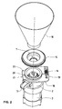
- Fig. 2 is screwed out of the housing 2 is the screw 7 with the attached drive wheel 15. Also pulled out of the screw 7 is the funnel 10.
- This annular holder 17 is formed in the embodiment shown here as a clamping ring 18.
- a headband 19 is mounted, in which the adjusting wheel 16 is rotatably supported.
- a clamping screw 21 is used, by means of which the clamping ring 18 can be fixed to the housing 2, wherein it is mounted on a housing height that the setting wheel 16 optimally can engage in the drive wheel 15.
- Fig. 3 shows in an enlarged view the clamping ring 18, with attached headband 19, in which the thumbwheel 16 is rotatably mounted, the slot 20 and the clamping screw 21 inserted in the clamping ring 18 in the region of the slot 20.
- the rotation of the screw 7 via the setting wheel 16 can be made for example by hand by a handwheel is attached to the axis 22 of the adjusting wheel 16, which protrudes through the housing of a coffee machine, in which this grinder is inserted, and on which the setting wheel 16 can be twisted.
- a scale can be mounted on this handwheel, on which, for example, the gap width of the grinding gap or the fineness of the ground coffee powder can be specified.
- this clamping ring 18 in any angular position, in particular to WegLabö réelle 13, placed and fixed on the clamping screw, thereby the adjusting wheel 16 can be arranged with the optionally attached drive in the inserted state of a grinder in a coffee machine there where enough space is available.
- FIG. 6 A further embodiment of the invention is made Fig. 6 seen.
- the grinder 1 has the same structure as the previously described grinder, consisting of a housing 2, on which the electric motor 3 is flanged. Again, this electric motor 3 drives the first grinding disk 6, the second grinding disk 9 is fastened to the screw-in part 7, which in turn can be screwed into the housing 2 via a threaded part 8. Inserted into the threaded part 8 is the funnel 10, the coffee beans are guided in an identical manner as in the previously described embodiment by the second grinding disc 9 in the grinding gap 12 for grinding. The ground coffee powder is brought into the removal opening 13, from where the coffee powder can get into the brewing device of a coffee machine in a known manner.
- a drive wheel 15 is fixed, which cooperates with a setting wheel 16, via which setting wheel 16, the drive wheel 15 and consequently the screw 7 can be rotated.
- the grinding gap 12 By turning the grinding gap 12 can be adjusted in turn.
- the thumbwheel 16 is in turn rotatably mounted on a headband 19, which headband 19 is attached to the annular support 17, which encloses the housing 2.
- the annular holder 17 in this embodiment consists of a ring 23 to which the headband 19 is attached.
- the thumbwheel 16 is held about the axis 22 rotatable.
- the axis may for example be equipped with an opening 27 which is formed, for example, as a hexagonal profile, in which a plug-in tool with a suitably trained plug-in profile can be used and with which the adjusting wheel 16 can be adjusted to adjust the Mahlspaltbreite.
- the annular surface 24 of the ring 23 is provided with a profiling 25, which may be, for example, a tooth profile.
- a profiling 26 is attached, when flanging the electric motor to the housing 2, the annular Holder 17 inserted therebetween, the profiling 25 of the ring 23 then engages in the profiling 26 of the housing, the ring 23 and thereby the headband 19 with the wheel 16 rotatably mounted therein are rotationally connected to the housing 2.
- Fig. 8 it can be seen, when flanging the electric motor 3 on the housing 2, the ring 23 inserted between the electric motor 3 and housing 2 can be brought into position such that the setting wheel 16 with respect to the Wegwareö réelle 13 in the correct angular position is at the onset of this grinder in to be a coffee maker in the right place.
- the electric motor 3 and the housing 2 can then be pushed together and connected to each other, the adjusting wheel 16 then comes into engagement with the drive wheel 15.
- the adjusting wheel 16 can be brought into an arbitrary position with respect to the removal opening 13, as in the 4 and 5 is shown, and is fixed in this position.
- the setting wheel 16 with respect to the housing 2 and in particular the Weg Kunststoffö réelle 13 can be placed in any angular position, in this angular position, the annular support 17 is held fixed, this angular position can be selected so that the thumbwheel 16 in a provided space can be accommodated in the coffee machine.
Landscapes
- Engineering & Computer Science (AREA)
- Food Science & Technology (AREA)
- Mechanical Engineering (AREA)
- Apparatus For Making Beverages (AREA)
- Crushing And Grinding (AREA)
- Apparatuses For Bulk Treatment Of Fruits And Vegetables And Apparatuses For Preparing Feeds (AREA)
- Tea And Coffee (AREA)
Description
- Die vorliegende Erfindung bezieht sich auf ein Mahlwerk für eine Kaffeemaschine, umfassend ein Gehäuse, in welchem eine erste Mahlscheibe angeordnet ist, welche über Antriebsmittel um eine Rotationsachse antreibbar ist, eine zweite Mahlscheibe, welche in einem Einschraubteil befestigt ist, welcher Einschraubteil in das Gehäuse einschraubbar ist und durch Verstellmittel bezüglich des Gehäuses verdrehbar ist und dadurch der Mahlspalt zwischen den beiden Mahlscheiben einstellbar ist, welche Verstellmittel aus einem koaxial zum Einschraubteil angeordneten Antriebsrad gebildet sind, welches mit einem über Stellmittel verdrehbaren Stellrad zusammenwirkt, welches Stellrad am Gehäuse befestigt ist, und eine im Gehäuse angeordnete Zuführöffnung für die Zuführung der zu mahlenden Kaffeebohnen und eine Wegführöffnung für das Wegführen des zwischen den beiden Mahlscheiben gemahlenen Kaffees.
- Derartige Mahlwerke für Kaffeemaschinen sind bekannt, beispielsweise zeigt die
EP-A 0676162 ein derartiges Mahlwerk. Bei derartigen Mahlwerken werden die Kaffeebohnen zwischen die beiden Mahlscheiben geführt, die eine Mahlscheibe wird über Antriebsmittel rotierend angetrieben, die andere Mahlscheibe ist feststehend, zwischen diesen Mahlscheiben werden die Kaffeebohnen zu Kaffeepulver gemahlen, dass gemahlene Kaffeepulver tritt radial aus dem Mahlspalt aus und wird über eine Austrittsöffnung beispielsweise der Brühkammer einer Kaffeemaschine zugeführt. - Um die Feinheit des Mahlpulvers einstellen zu können, lässt sich die feststehende Mahlscheibe gegen die angetriebene Mahlscheibe hin bzw. von dieser weg bewegen, wozu diese feststehende Mahlscheibe auf einem Einschraubteil, der in das Gehäuse einschraubbar ist, befestigt ist. Dieser Einschraubteil ist mit einem Antriebsrad versehen, welches über einen Stellantrieb bezüglich des Gehäuses verdreht werden kann.
- Derartige Mahlwerke sollen in möglichst viele unterschiedliche Kaffeemaschinentypen eingesetzt werden können. Die bezüglich der Mahlscheiben radial ausgerichtete Wegführöffnung für das gemahlene Kaffeepulver ist hierbei festgelegt, der Stellantrieb für das Antriebsrad zum Einstellen der Spaltbreite zwischen den Mahlscheiben ist bezüglich der Wegführöffnung fest am Gehäuse angebracht, je nachdem, wie die Platzverhältnisse an den unterschiedlichen Kaffeemaschinentypen ausgestattet sind, muss dieser Stellantrieb bezüglich der Wegführöffnung für das Kaffeepulver an verschiedenen Positionen angeordnet werden, was zur Folge hat, dass eine Auswahlmöglichkeit an entsprechend ausgebildeten Mahlwerken vorhanden sein muss, was die Produktionskosten für diese Mahlwerke und deren Lagerhaltung erhöht.
- Die Aufgabe der vorliegenden Erfindung besteht darin, ein Mahlwerk für eine Kaffeemaschine so auszugestalten, dass das Stellrad mit dem Stellantrieb zum Einstellen des Mahlspaltes zwischen den beiden Mahlscheiben bezüglich der Wegführöffnung, die am Gehäuse befestigt ist, in eine beliebige Position gebracht und fixiert werden kann.
- Erfindungsgemäss erfolgt die Lösung dieser Aufgabe dadurch, dass das Stellrad an einer Halterung angeordnet ist, welche am Gehäuse angebracht ist und welche bezüglich des Gehäuses verstellbar und in jeder Position fixierbar ist.
- Dadurch kann ein Einheitsmahlwerk für unterschiedliche Kaffeemaschinentypen produziert werden, je nach den Platzverhältnissen in der Kaffeemaschine kann das Stellrad in eine entsprechende Position gebracht und in dieser Position fixiert werden.
- In vorteilhafter Weise ist das Stellrad an einer ringförmigen Halterung angeordnet, welche das Gehäuse umschliesst und welche bezüglich des Gehäuses verdrehbar und in jeder Position fixierbar ist, wodurch ein einfacher Aufbau und eine einfache Verstellbarkeit des Stellrades erreichbar ist.
- In vorteilhafter Weise ist das Stellrad in einem Haltbügel drehbar gelagert, welcher Haltebügel an der ringförmigen Halterung befestigt ist. Dadurch wird erreicht, dass die ringförmige Halterung unterhalt oder oberhalb des Antriebsrades auf das Gehäuse aufgestülpt werden kann, und dass das Stellrad in optimaler Weise mit dem Antriebsrad in Eingriff kommt.
- In vorteilhafter Weise ist die ringförmige Halterung als Spannring ausgebildet, welcher über Spannmittel in der eingestellten Position fixierbar ist, was eine sehr einfache Konstruktion und Herstellung der ringförmigen Halterung ergibt, die in einfacher Weise am Gehäuse montierbar ist.
- In vorteilhafter Weise bestehen die Spannmittel aus einer Spannschraube, mittels welcher der Spannring auf der Umfangsoberfläche des Gehäuses spannbar ist, was eine besonders einfache Handhabung bei der Montage ergibt.
- Die ringförmige Halterung kann auch aus einem Ring gebildet sein, welcher mit einer mindestens über einen Teil des Umfangs sich erstreckenden Profilierung ausgestattet ist, welche in eine entsprechend am Umfang des Gehäuses angebrachte Profilierung eingreift. Durch diese Profilierung wird ein verdrehsicheres Halten in einer voreinstellbaren Position der ringförmigen Halterung am Gehäuse erreicht.
- Das Verstellen des Stellrades kann über ein von Hand betätigbares Steckwerkzeug ausgeführt werden, welches mit einem Steckprofil versehen ist, welches in eine entsprechend ausgebildete Öffnung des Stellrades einsteckbar ist. Das Stellrad kann aber auch motorisch angetrieben werden, dadurch kann das Antriebsrad gesteuert in die gewünschte Position gebracht werden.
- In vorteilhafter Weise ist das Antriebsrad als Schneckenrad und das Stellrad als Schnecke ausgebildet, was einen besonders einfachen Verstellmechanismus ergibt.
- Ausführungsformen der Erfindung werden nachfolgend anhand der beiliegenden Zeichnungen beispielhaft näher erläutert.
- Es zeigt
-
Fig. 1 eine Schnittdarstellung durch ein Mahlwerk mit einer ersten Ausgestaltung einer ringförmigen Halterung für das Stellrad; -
Fig. 2 in räumlicher Darstellung das Mahlwerk gemässFig. 1 in auseinander gezogenem Zustand; -
Fig. 3 eine räumliche Darstellung der als Spannring ausgebildeten ringförmigen Halterung; -
Fig. 4 und Fig. 5 jeweils eine Ansicht auf das Antriebsrad des Mahlwerks mit in unterschiedlichen Positionen angeordneten Stellrädern; -
Fig. 6 eine Schnittdarstellung eines Mahlwerks mit einer weiteren Ausführungsform einer ringförmigen Halterung; -
Fig. 7 in räumlicher Darstellung die ringförmige Halterung gemässFig. 6 mit dem dazugehörigen entsprechenden Gehäuseteil des Mahlwerks; -
Fig. 8 eine Ansicht auf das Mahlwerk gemässFig. 6 mit angehobenem Gehäuse, um die ringförmige Halterung positionieren zu können. - Wie aus
Fig. 1 ersichtlich ist, besteht das Mahlwerk 1 aus einem Gehäuse 2, auf welches in bekannter Weise ein Elektromotor 3 aufgeflanscht ist. - Auf die Achse 4 des Elektromotors 3 ist ein Aufnahmeteil 5 aufgesetzt, in welchem die erste Mahlscheibe 6 eingesetzt und befestigt ist.
- In das Gehäuse 2 eingeschraubt ist ein Einschraubteil 7, wozu das Gehäuse 2 und der Einschraubteil 7 mit jeweils einem korrespondierenden Gewindeteil 8 ausgestattet sind. Am Einschraubteil 7 ist die zweite Mahlscheibe 9 befestigt, dergestalt, dass sie koaxial und gegenüberliegend der ersten Mahlscheibe 6 angeordnet ist. Die beiden einander zugewandten Ringflächen der ersten Mahlscheibe 6 und der zweiten Mahlscheibe 9 sind in bekannter Weise mit Schneiden ausgestattet, zudem sind die Mahlscheiben 6 und 9 sphärisch und konisch gestaltet. Auf den Einschraubteil 7 aufgesetzt ist ein Trichter 10, in welchen die zu mahlenden Kaffeebohnen eingefüllt werden können. Diese Kaffeebohnen gelangen beim Mahlvorgang über eine koaxiale Öffnung 11, die in der zweiten Mahlscheibe angebracht ist, in den durch die beiden Mahlscheiben 6 und 9 gebildeten Mahlspalt 12. Beim Rotieren der ersten Mahlscheibe 6 werden die Kaffeebohnen vom Zentrum zur Peripherie der beiden Mahlscheiben 6 und 9 gefördert, auf diesem Weg werden die Kaffeebohnen zu Kaffeepulver verkleinert. Die nicht dargestellten, bekannten Pulverauswerfer, die am Umfang der ersten Mahlscheibe 6 angeordnet sind, schieben das Kaffeepulver zur am Gehäuse angebrachten Wegführöffnung 13, durch welche das gemahlene Kaffeepulver komprimiert weggeführt wird, um beispielsweise in eine Brühkammer einer Kaffeemaschine geleitet zu werden. Durch ein im Zentrum der ersten Mahlscheibe 6 befestigten, pilzförmigen Element 14 wird vermieden, dass ein Betreiber dieses Mahlwerks beispielsweise durch den Trichter 10 und die koaxiale Öffnung 11 in den Mahlspalt 12 und damit in die Schneiden der beiden Mahlscheiben 6 und 9 greifen kann.
- Am Gewindeteil 8 ist ein Antriebsrad 15 angebracht, das im vorliegenden Ausführungsbeispiel als Schneckenrad ausgebildet ist. Das Schneckenrad 15 kann über ein mit diesem kämmenden Stellrad 16 verdreht werden, wobei in diesem Ausführungsbeispiel das Stellrad 16 als Schnecke ausgebildet ist. Das Stellrad 16 ist, wie später im Detail noch beschrieben wird, in einer ringförmigen Halterung 17 angeordnet, welche das Gehäuse 2 umschliesst und an diesem fixiert ist.
- Durch Verdrehen des Stellrades 16 wird das Antriebsrad 15 und zusammen mit diesem der Gewindeteil 8 bezüglich des Gehäuses 2 verdreht, beim Verdrehen des Einschraubteils 7 wird dieser in das Gehäuse 2 eingeschraubt oder aus diesem herausgeschraubt, wodurch sich der Mahlspalt 12 verändert. Dadurch kann der Mahlspalt 12 eingestellt werden, wodurch unterschiedliche Feinheiten des gemahlenen Kaffeepulvers erreicht werden können.
-
Fig. 2 zeigt das Gehäuse 2 mit dem daran befestigten Elektromotor 3. Aus dem Gehäuse 2 ausgeschraubt ist der Einschraubteil 7 mit dem daran angebrachten Antriebsrad 15. Ebenfalls aus dem Einschraubteil 7 herausgezogen ist der Trichter 10. Auf das Gehäuse 2 aufgesetzt, ist die ringförmige Halterung 17, auf welcher das Stellrad 16 verdrehbar gehalten ist. Diese ringförmige Halterung 17 ist im hier dargestellten Ausführungsbeispiel als Spannring 18 ausgebildet. Auf der einen Seite dieses Spannrings 18 ist ein Haltebügel 19 angebracht, in welchen das Stellrad 16 drehbar gehalten ist. Auf der dem Haltebügel gegenüberliegenden Seite ist der Spannring mit einem Schlitz 20 versehen, in diesem Bereich ist eine Spannschraube 21 eingesetzt, mittels welcher der Spannring 18 auf dem Gehäuse 2 fixiert werden kann, wobei er auf einer Gehäusehöhe angebracht wird, dass das Stellrad 16 optimal in das Antriebsrad 15 eingreifen kann. -
Fig. 3 zeigt in vergrösserter Darstellung den Spannring 18, mit angebrachtem Haltebügel 19, in welchem das Stellrad 16 verdrehbar gelagert ist, den Schlitz 20 und die im Bereich des Schlitzes 20 in den Spannring 18 eingesetzten Spannschraube 21. - Das Verdrehen des Einschraubteils 7 über das Stellrad 16 kann beispielsweise von Hand vorgenommen werden, indem an der Achse 22 des Stellrades 16 ein Handrad befestigt ist, das durch das Gehäuse einer Kaffeemaschine, in welche dieses Mahlwerk eingesetzt ist, hindurchragt, und über welches das Stellrad 16 verdreht werden kann. Hierzu kann auf diesem Handrad beispielsweise eine Skala angebracht sein, auf welcher beispielsweise die Spaltbreite des Mahlspaltes oder die Feinheit des gemahlenen Kaffeepulvers angegeben sein kann.
- Wie aus den
Fig. 4 und 5 ersichtlich ist, kann dieser Spannring 18 in einer beliebigen Winkellage, insbesondere zur Wegführöffnung 13, aufgesetzt und über die Spannschraube fixiert werden, dadurch kann das Stellrad 16 mit dem gegebenenfalls angebrachten Antrieb im eingesetzten Zustand eines Mahlwerks in eine Kaffeemaschine dort angeordnet werden, wo genügend Platz vorhanden ist. - Eine weitere Ausgestaltung der Erfindung ist aus
Fig. 6 ersichtlich. Das Mahlwerk 1 ist gleich aufgebaut, wie das vorgängig beschriebene Mahlwerk, bestehend aus einem Gehäuse 2, auf welches der Elektromotor 3 aufgeflanscht ist. Wiederum treibt dieser Elektromotor 3 die erste Mahlscheibe 6 an, die zweite Mahlscheibe 9 ist am Einschraubteil 7 befestigt, welcher wiederum über einen Gewindeteil 8 in das Gehäuse 2 einschraubbar ist. In den Gewindeteil 8 eingesetzt ist der Trichter 10, die Kaffeebohnen werden in identischer Weise wie beim vorgängig beschriebenen Ausführungsbeispiel durch die zweite Mahlscheibe 9 in den Mahlspalt 12 zum Mahlen geführt. Das gemahlene Kaffeepulver wird in die Wegführöffnung 13 gebracht, von wo das Kaffeepulver in bekannter Weise in die Brüheinrichtung einer Kaffeemaschine gelangen kann. - Am Einschraubteil 7 ist wiederum ein Antriebsrad 15 befestigt, welches mit einem Stellrad 16 zusammenwirkt, über welches Stellrad 16 das Antriebsrad 15 und demzufolge der Einschraubteil 7 verdreht werden kann. Durch das Verdrehen lässt sich wiederum der Mahlspalt 12 einstellen.
- Das Stellrad 16 ist wiederum auf einem Haltebügel 19 drehbar gelagert, welcher Haltebügel 19 an der ringförmigen Halterung 17 befestigt ist, welche das Gehäuse 2 umschliesst.
- Wie insbesondere aus
Fig. 7 ersichtlich ist, besteht die ringförmige Halterung 17 in diesem Ausführungsbeispiel aus einem Ring 23, an welchem der Haltebügel 19 befestigt ist. Im Haltebügel 19 ist das Stellrad 16 um die Achse 22 verdrehbar gehalten. Hierbei kann die Achse beispielsweise mit einer Öffnung 27 ausgestattet sein, die beispielsweise als Sechskantprofil ausgebildet ist, in welche ein Steckwerkzeug mit entsprechend ausgebildetem Steckprofil eingesetzt werden kann und mit welchem das Stellrad 16 verstellt werden kann, zur Einstellung der Mahlspaltbreite. - Die ringförmige Oberfläche 24 des Rings 23 ist mit einer Profilierung 25 ausgestattet, die beispielsweise ein Zahnprofil sein kann. An der Unterseite des Gehäuses 2 ist eine entsprechende Profilierung 26 angebracht, beim Anflanschen des Elektromotors an das Gehäuse 2 wird die ringförmige Halterung 17 dazwischen eingesetzt, die Profilierung 25 des Ringes 23 greift dann in die Profilierung 26 des Gehäuses ein, der Ring 23 und dadurch der Haltebügel 19 mit dem darin verdrehbar gelagerten Stellrad 16 sind verdrehfest mit dem Gehäuse 2 verbunden.
- Wie aus
Fig. 8 ersichtlich ist, kann beim Aufflanschen des Elektromotors 3 auf das Gehäuse 2 der zwischen Elektromotor 3 und Gehäuse 2 eingesetzte Ring 23 derart in Position gebracht werden, dass das Stellrad 16 bezüglich der Wegführöffnung 13 in der richtigen Winkellage sich befindet, um beim Einsetzen dieses Mahlwerks in eine Kaffeemaschine am richtigen Platz zu sein. Der Elektromotor 3 und das Gehäuse 2 können dann zusammengeschoben und miteinander verbunden werden, das Stellrad 16 kommt dann in Eingriff mit dem Antriebsrad 15. Dadurch kann das Stellrad 16 bezüglich der Wegführöffnung 13 in eine beliebige Position gebracht werden, wie dies in denFig. 4 und 5 dargestellt ist, und ist in dieser Position fixiert. - Mit dieser erfindungsgemässen Ausgestaltung eines Mahlwerks kann das Stellrad 16 bezüglich des Gehäuses 2 und insbesondere der Wegführöffnung 13 in eine beliebige Winkellage gebracht werden, in dieser Winkellage wird die ringförmige Halterung 17 fixiert gehalten, diese Winkellage kann so gewählt werden, dass das Stellrad 16 in einem dafür vorgesehenen Platz in der Kaffeemaschine untergebracht werden kann. Dadurch kann ein Einheitsmahlwerk in verschiedenartige Kaffeemaschinen eingesetzt werden.
Claims (9)
- Mahlwerk für eine Kaffeemaschine, umfassend ein Gehäuse (2), in welchem eine erste Mahlscheibe (6) angeordnet ist, welche über Antriebsmittel (3) um eine Rotationsachse antreibbar ist, eine zweite Mahlscheibe (9), welche in einem Einschraubteil (7) befestigt ist, welcher Einschraubteil (7) in das Gehäuse (2) einschraubbar ist und durch Verstellmittel (15, 16) bezüglich des Gehäuses (2) verdrehbar ist und dadurch der Mahlspalt (12) zwischen den beiden Mahlscheiben (6, 9) einstellbar ist, welche Verstellmittel aus einem koaxial zum Einschraubteil (7) angeordneten Antriebsrad (15) gebildet sind, welches mit einem über Stellmittel verdrehbaren Stellrad (16) zusammenwirkt, welches Stellrad (16) am Gehäuse (2) befestigt ist, und eine im Gehäuse (2) angeordnete Zuführöffnung für die Zuführung der zu mahlenden Kaffeebohnen und eine Wegführöffnung (13) für das Wegführen des zwischen den beiden Mahlscheiben (6, 9) gemahlenen Kaffees, dadurch gekennzeichnet, dass das Stellrad (16) an einer Halterung (17) angeordnet ist, welche am Gehäuse (2) angebracht ist und welche bezüglich des Gehäuses (2) verstellbar und in jeder Position fixierbar ist.
- Mahlwerk nach Anspruch 1, dadurch gekennzeichnet, dass die Halterung (17) ringförmig ausgebildet ist und das Gehäuse (2) umschliesst und welche ringförmige Halterung bezüglich des Gehäuses (2) verdrehbar und in jeder Position fixierbar ist.
- Mahlwerk nach Anspruch 2, dadurch gekennzeichnet, dass das Stellrad (16) in einem Haltebügel (19) drehbar gelagert ist, welcher Haltebügel (19) an der ringförmigen Halterung (17) befestigt ist.
- Mahlwerk nach Anspruch 2 oder 3, dadurch gekennzeichnet, dass die ringförmige Halterung (17) als Spannring (18) ausgebildet ist, welcher über Spannmittel (21) in der eingestellten Position fixierbar ist.
- Mahlwerk nach Anspruch 4, dadurch gekennzeichnet, dass die Spannmittel (21) aus einer Spannschraube bestehen, mittels welcher der Spannring (18) auf der Umfangsoberfläche des Gehäuses (2) spannbar ist.
- Mahlwerk nach Anspruch 2 oder 3, dadurch gekennzeichnet, dass die ringförmige Halterung (17) aus einem Ring (23) gebildet ist, welcher mit einer mindestens über einen Teil des Umfangs sich erstreckenden Profilierung (25) ausgestattet ist, welche in eine entsprechend am Umfang des Gehäuses (2) angebrachte Profilierung (26) eingreift.
- Mahlwerk nach einem der Ansprüche 1 bis 6, dadurch gekennzeichnet, dass die Stellmittel aus einem Steckwerkzeug mit einem Steckprofil bestehen, welches in eine entsprechend ausgebildete Öffnung (27) des Stellrades (16) einsteckbar ist.
- Mahlwerk nach einem der Ansprüche 1 bis 6, dadurch gekennzeichnet, dass die Stellmittel einen motorischen Antrieb umfassen, mittels welchem das Stellrad (16) gesteuert motorisch antreibbar ist
- Mahlwerk nach einem der Ansprüche 1 bis 8, dadurch gekennzeichnet, dass das Antriebsrad (15) als Schneckenrad und das Stellrad (16) als Schnecke ausgebildet sind.
Priority Applications (6)
| Application Number | Priority Date | Filing Date | Title |
|---|---|---|---|
| EP09168396A EP2286699B1 (de) | 2009-08-21 | 2009-08-21 | Mahlwerk für eine Kaffeemaschine |
| DK09168396.1T DK2286699T3 (da) | 2009-08-21 | 2009-08-21 | Maleværk til en kaffemaskine |
| AT09168396T ATE541492T1 (de) | 2009-08-21 | 2009-08-21 | Mahlwerk für eine kaffeemaschine |
| ES09168396T ES2380402T3 (es) | 2009-08-21 | 2009-08-21 | Molinillo para una máquina de café |
| US13/389,831 US8763942B2 (en) | 2009-08-21 | 2010-08-12 | Grinder for a coffee machine |
| PCT/EP2010/061766 WO2011020771A1 (de) | 2009-08-21 | 2010-08-12 | Mahlwerk für eine kaffeemaschine |
Applications Claiming Priority (1)
| Application Number | Priority Date | Filing Date | Title |
|---|---|---|---|
| EP09168396A EP2286699B1 (de) | 2009-08-21 | 2009-08-21 | Mahlwerk für eine Kaffeemaschine |
Publications (2)
| Publication Number | Publication Date |
|---|---|
| EP2286699A1 EP2286699A1 (de) | 2011-02-23 |
| EP2286699B1 true EP2286699B1 (de) | 2012-01-18 |
Family
ID=41667329
Family Applications (1)
| Application Number | Title | Priority Date | Filing Date |
|---|---|---|---|
| EP09168396A Active EP2286699B1 (de) | 2009-08-21 | 2009-08-21 | Mahlwerk für eine Kaffeemaschine |
Country Status (6)
| Country | Link |
|---|---|
| US (1) | US8763942B2 (de) |
| EP (1) | EP2286699B1 (de) |
| AT (1) | ATE541492T1 (de) |
| DK (1) | DK2286699T3 (de) |
| ES (1) | ES2380402T3 (de) |
| WO (1) | WO2011020771A1 (de) |
Cited By (2)
| Publication number | Priority date | Publication date | Assignee | Title |
|---|---|---|---|---|
| WO2021037546A1 (de) | 2019-08-27 | 2021-03-04 | Melitta Professional Coffee Solutions GmbH & Co. KG | Mahlwerk und kaffeemaschine mit einem solchen mahlwerk |
| US12082743B2 (en) | 2018-06-29 | 2024-09-10 | Melitta Professional Coffee Solutions GmbH & Co. KG | Grinder, coffee machine and method for grinding coffee beans |
Families Citing this family (20)
| Publication number | Priority date | Publication date | Assignee | Title |
|---|---|---|---|---|
| USD899194S1 (en) * | 2007-11-29 | 2020-10-20 | Automatic Bar Controls, Inc. | Dispensing apparatus |
| CH707603A1 (de) | 2013-02-12 | 2014-08-15 | Wmf Württembergische Metallwarenfabrik Ag | Verfahren zum Überwachen und/oder Steuern eines Getränkebereiters sowie Getränkebereiter zur Durchführung des Verfahrens. |
| CH708196B1 (de) * | 2013-06-06 | 2017-05-15 | Steiner Ag Weggis | Kaffeemühle, insbesondere für eine automatische Kaffeemaschine. |
| US10239062B2 (en) * | 2013-08-05 | 2019-03-26 | Sharp Kabushiki Kaisha | Mill and beverage preparation apparatus including the same |
| JP6242220B2 (ja) * | 2014-01-31 | 2017-12-06 | シャープ株式会社 | 粉砕装置 |
| JP6276127B2 (ja) * | 2014-07-17 | 2018-02-07 | 象印マホービン株式会社 | コーヒー豆粉砕装置 |
| JP6465696B2 (ja) * | 2015-03-02 | 2019-02-06 | シャープ株式会社 | 粉砕装置および飲料製造装置 |
| TWI735654B (zh) * | 2016-09-19 | 2021-08-11 | 義大利商辛巴利集團公司 | 用於適用製造飲料之植物性產品,尤其是烤咖啡豆的研磨裝置之研磨室 |
| IT201700038061A1 (it) | 2017-04-06 | 2018-10-06 | Mazzer Luigi Spa | Macinadosatore per caffe’ con regolazione automatica della granulometria di macinatura e relativo metodo di regolazione |
| IT201700038863A1 (it) * | 2017-04-07 | 2018-10-07 | Mazzer Luigi Spa | Macinadosatore per caffe’ con protezione del dispositivo di pesatura alla polvere di caffe’ |
| CA3010942A1 (en) * | 2017-07-18 | 2019-01-18 | Gruppo Cimbali S.P.A. | Device for resetting the position of the grinding wheels in a grinder |
| CN107981728B (zh) * | 2017-12-26 | 2020-04-14 | 威斯达电器(中山)制造有限公司 | 磨豆装置及磨豆咖啡机 |
| IT201800003924A1 (it) | 2018-03-26 | 2019-09-26 | De Longhi Appliances Srl | Macinino per macchina da caffè automatica |
| NL2022259B1 (nl) * | 2018-12-20 | 2020-07-14 | J M De Jong Duke Automatenfabriek B V | Maalinrichting, koffiemachine en werkwijze voor het instellen daarvan |
| NL2022272B1 (nl) | 2018-12-20 | 2020-07-15 | J M De Jong Duke Automatenfabriek B V | Maalinrichting, koffiemachine en werkwijze voor het instellen daarvan |
| ES2908647T3 (es) * | 2019-10-10 | 2022-05-03 | Hemro Int Ag | Molinillo de café |
| DE102022214361A1 (de) * | 2022-12-23 | 2024-07-04 | BSH Hausgeräte GmbH | Kaffeemaschine mit getriebelosem Antrieb |
| US12575692B2 (en) | 2024-01-18 | 2026-03-17 | Sharkninja Operating Llc | Suggesting coffee bean grind size for beverage machines |
| US12369744B1 (en) | 2024-01-18 | 2025-07-29 | Sharkninja Operating Llc | Preparation of beverage machines for cold beverage brewing |
| WO2025155323A1 (en) | 2024-01-18 | 2025-07-24 | Sharkninja Operating Llc | Preventing coffee bean grinder jamming |
Family Cites Families (14)
| Publication number | Priority date | Publication date | Assignee | Title |
|---|---|---|---|---|
| US2229031A (en) * | 1937-12-28 | 1941-01-21 | Standard Computing Scale Compa | Coffee grinder |
| US4605175A (en) * | 1984-09-10 | 1986-08-12 | Webston, Inc. | Precision coffee grinder |
| IT209821Z2 (it) * | 1987-01-15 | 1988-11-04 | Tedioli Pier Giorgio | Apparecchio elettrico a macina, per macinare pepe o sale. |
| US4967649A (en) * | 1989-08-16 | 1990-11-06 | Modern Process Equipment, Inc. | Coffee grinder |
| ATE185688T1 (de) | 1994-04-11 | 1999-11-15 | Schaerer Ag M | Kaffeemaschine mit einer mahleinrichtung |
| JP3297578B2 (ja) * | 1996-02-20 | 2002-07-02 | 相川鉄工株式会社 | リファイナ |
| KR100552222B1 (ko) * | 2003-04-11 | 2006-02-14 | 주식회사 롯데기공 | 원두커피 분쇄장치 |
| ITFI20060281A1 (it) * | 2006-11-14 | 2008-05-15 | Saeco Ipr Ltd | Organi di macinazione per un dispositivo macina caffe' ed una macchina da caffe' comprendente tale dispositivo. |
| EP1994866A1 (de) * | 2007-05-23 | 2008-11-26 | Rhea Vendors S.p.A. | Vorrichtung zum Mahlen von Kaffee oder anderen Nahrungsmitteln |
| CN201067340Y (zh) * | 2007-07-24 | 2008-06-04 | 宁波夏纳电器有限公司 | 全自动咖啡机的咖啡豆磨豆系统及咖啡粉挤压系统 |
| US7874505B1 (en) * | 2007-08-31 | 2011-01-25 | Food Equipment Technologies Company, Inc. | Food grinder with electronically adjustable grind settings, tooless disassembly |
| IT1397305B1 (it) * | 2009-12-01 | 2013-01-04 | Mazzer Luigi S R L | Dispositivo di bloccaggio della regolazione micrometrica della macinazione in macina caffe'. |
| FR2956307B3 (fr) * | 2010-02-17 | 2012-10-05 | Sara Lee/De N V | Systeme pour boisson au cafe, appareil de preparation de cafe, cartouche d'emballage pour grains de cafe et procede de preparation de cafe |
| DE102010017721A1 (de) * | 2010-07-05 | 2010-12-30 | SEVERIN ELEKTROGERÄTE GmbH | Mahlwerk |
-
2009
- 2009-08-21 DK DK09168396.1T patent/DK2286699T3/da active
- 2009-08-21 AT AT09168396T patent/ATE541492T1/de active
- 2009-08-21 ES ES09168396T patent/ES2380402T3/es active Active
- 2009-08-21 EP EP09168396A patent/EP2286699B1/de active Active
-
2010
- 2010-08-12 US US13/389,831 patent/US8763942B2/en active Active
- 2010-08-12 WO PCT/EP2010/061766 patent/WO2011020771A1/de not_active Ceased
Cited By (2)
| Publication number | Priority date | Publication date | Assignee | Title |
|---|---|---|---|---|
| US12082743B2 (en) | 2018-06-29 | 2024-09-10 | Melitta Professional Coffee Solutions GmbH & Co. KG | Grinder, coffee machine and method for grinding coffee beans |
| WO2021037546A1 (de) | 2019-08-27 | 2021-03-04 | Melitta Professional Coffee Solutions GmbH & Co. KG | Mahlwerk und kaffeemaschine mit einem solchen mahlwerk |
Also Published As
| Publication number | Publication date |
|---|---|
| ATE541492T1 (de) | 2012-02-15 |
| ES2380402T3 (es) | 2012-05-11 |
| US20120138721A1 (en) | 2012-06-07 |
| EP2286699A1 (de) | 2011-02-23 |
| US8763942B2 (en) | 2014-07-01 |
| DK2286699T3 (da) | 2012-04-23 |
| WO2011020771A1 (de) | 2011-02-24 |
Similar Documents
| Publication | Publication Date | Title |
|---|---|---|
| EP2286699B1 (de) | Mahlwerk für eine Kaffeemaschine | |
| EP2810592B1 (de) | Kaffeemühle, insbesondere für eine automatische Kaffeemaschine | |
| EP2858539B1 (de) | Kaffeemaschine | |
| EP1575740B1 (de) | Elektrohandwerkzeugmaschine | |
| EP2384853B1 (de) | Doppelseitenschleifmaschine | |
| EP2286698A1 (de) | Mahlwerk für eine Kaffeemaschine | |
| DE102019122996A1 (de) | Mahlwerk und Kaffeemaschine mit einem solchen Mahlwerk | |
| EP1493368B1 (de) | Kaffeemühle für eine Kaffeemaschine | |
| EP3216375A1 (de) | Kaffeemühle sowie kaffeevollautomat mit kaffeemühle | |
| DE29809485U1 (de) | Wolf zum Zerkleinern von Gefrier- und Frischfleisch | |
| DE4338903A1 (de) | Zerkleinerungsmaschine und Einrichtung zur Einstellung des Spaltes einer solchen Zerkleinerungsmaschine | |
| WO2021004836A1 (de) | Einheit einer kaffeevorrichtung | |
| BE1024026B1 (de) | Einstellvorrichtung für einen Schleifstein einer Schleifvorrichtung eines Häckselwerks und Verfahren zur Einstellung eines Schleifsteins | |
| EP4076114A1 (de) | Mahlwerk, mahlscheibe für ein mahlwerk, und kaffeemaschine mit einem solchen mahlwerk | |
| DE3239137C2 (de) | Vorrichtung zum Einstellen des Abstandes zwischen einem freistehenden und einem drehbaren Mahlstein einer Mühle, insbesondere Getreidemühle | |
| DE1117438B (de) | Zerkleinerungsmaschine fuer Fleisch, Brot od. dgl. | |
| DE2447380C3 (de) | Vorrichtung zum Einstellen des Mahlsteinabstandes einer Getreidemühle | |
| DE881296C (de) | Kopfschlitzmaschine fuer Schraubenrohlinge od. dgl. | |
| DE3914977A1 (de) | Schleifgeraet zum nacharbeiten von skikanten | |
| DE349575C (de) | Maschine zum Abschleifen von Schraubenfedern an ihren Auflageflaechen | |
| EP0512373A2 (de) | Vorrichtung zur Halterung eines Werkzeuges | |
| DE604047C (de) | Schneidvorrichtung fuer Strangzigarettenmaschinen | |
| DE836141C (de) | Vorrichtung zum Mahlen oder Reissen von faserigem Material, beispielsweise Zellstoff od. dgl. | |
| AT222532B (de) | Zerkleinerungsmaschine für Fleisch, Brot od. dgl. | |
| DE433628C (de) | Muehle zum Vermahlen von Kaffee o. dgl. |
Legal Events
| Date | Code | Title | Description |
|---|---|---|---|
| PUAI | Public reference made under article 153(3) epc to a published international application that has entered the european phase |
Free format text: ORIGINAL CODE: 0009012 |
|
| AK | Designated contracting states |
Kind code of ref document: A1 Designated state(s): AT BE BG CH CY CZ DE DK EE ES FI FR GB GR HR HU IE IS IT LI LT LU LV MC MK MT NL NO PL PT RO SE SI SK SM TR |
|
| AX | Request for extension of the european patent |
Extension state: AL BA RS |
|
| 17P | Request for examination filed |
Effective date: 20110517 |
|
| GRAP | Despatch of communication of intention to grant a patent |
Free format text: ORIGINAL CODE: EPIDOSNIGR1 |
|
| RIC1 | Information provided on ipc code assigned before grant |
Ipc: A47J 42/18 20060101ALI20110622BHEP Ipc: A47J 31/42 20060101AFI20110622BHEP |
|
| GRAS | Grant fee paid |
Free format text: ORIGINAL CODE: EPIDOSNIGR3 |
|
| GRAA | (expected) grant |
Free format text: ORIGINAL CODE: 0009210 |
|
| RIN1 | Information on inventor provided before grant (corrected) |
Inventor name: GRUPP, MARTIN Inventor name: GUSSMANN, JOCHEN Inventor name: STARTZ, ARMIN Inventor name: CAPUTO, CIRO Inventor name: KIEFER, ALEXANDER Inventor name: STOHRER, HELMUT Inventor name: ARNDT, PETER Inventor name: HERGESELL, HARALD |
|
| AK | Designated contracting states |
Kind code of ref document: B1 Designated state(s): AT BE BG CH CY CZ DE DK EE ES FI FR GB GR HR HU IE IS IT LI LT LU LV MC MK MT NL NO PL PT RO SE SI SK SM TR |
|
| REG | Reference to a national code |
Ref country code: GB Ref legal event code: FG4D Free format text: NOT ENGLISH |
|
| REG | Reference to a national code |
Ref country code: CH Ref legal event code: EP |
|
| REG | Reference to a national code |
Ref country code: AT Ref legal event code: REF Ref document number: 541492 Country of ref document: AT Kind code of ref document: T Effective date: 20120215 Ref country code: IE Ref legal event code: FG4D Free format text: LANGUAGE OF EP DOCUMENT: GERMAN |
|
| REG | Reference to a national code |
Ref country code: CH Ref legal event code: NV Representative=s name: BOVARD AG |
|
| REG | Reference to a national code |
Ref country code: DE Ref legal event code: R096 Ref document number: 502009002473 Country of ref document: DE Effective date: 20120322 |
|
| REG | Reference to a national code |
Ref country code: NL Ref legal event code: T3 |
|
| REG | Reference to a national code |
Ref country code: DK Ref legal event code: T3 |
|
| REG | Reference to a national code |
Ref country code: SE Ref legal event code: TRGR |
|
| REG | Reference to a national code |
Ref country code: ES Ref legal event code: FG2A Ref document number: 2380402 Country of ref document: ES Kind code of ref document: T3 Effective date: 20120511 |
|
| LTIE | Lt: invalidation of european patent or patent extension |
Effective date: 20120118 |
|
| PG25 | Lapsed in a contracting state [announced via postgrant information from national office to epo] |
Ref country code: HR Free format text: LAPSE BECAUSE OF FAILURE TO SUBMIT A TRANSLATION OF THE DESCRIPTION OR TO PAY THE FEE WITHIN THE PRESCRIBED TIME-LIMIT Effective date: 20120118 Ref country code: LT Free format text: LAPSE BECAUSE OF FAILURE TO SUBMIT A TRANSLATION OF THE DESCRIPTION OR TO PAY THE FEE WITHIN THE PRESCRIBED TIME-LIMIT Effective date: 20120118 Ref country code: IS Free format text: LAPSE BECAUSE OF FAILURE TO SUBMIT A TRANSLATION OF THE DESCRIPTION OR TO PAY THE FEE WITHIN THE PRESCRIBED TIME-LIMIT Effective date: 20120518 Ref country code: BG Free format text: LAPSE BECAUSE OF FAILURE TO SUBMIT A TRANSLATION OF THE DESCRIPTION OR TO PAY THE FEE WITHIN THE PRESCRIBED TIME-LIMIT Effective date: 20120418 Ref country code: NO Free format text: LAPSE BECAUSE OF FAILURE TO SUBMIT A TRANSLATION OF THE DESCRIPTION OR TO PAY THE FEE WITHIN THE PRESCRIBED TIME-LIMIT Effective date: 20120418 |
|
| REG | Reference to a national code |
Ref country code: CH Ref legal event code: NV Representative=s name: RENTSCH PARTNER AG Ref country code: IE Ref legal event code: FD4D |
|
| PG25 | Lapsed in a contracting state [announced via postgrant information from national office to epo] |
Ref country code: PL Free format text: LAPSE BECAUSE OF FAILURE TO SUBMIT A TRANSLATION OF THE DESCRIPTION OR TO PAY THE FEE WITHIN THE PRESCRIBED TIME-LIMIT Effective date: 20120118 Ref country code: PT Free format text: LAPSE BECAUSE OF FAILURE TO SUBMIT A TRANSLATION OF THE DESCRIPTION OR TO PAY THE FEE WITHIN THE PRESCRIBED TIME-LIMIT Effective date: 20120518 Ref country code: FI Free format text: LAPSE BECAUSE OF FAILURE TO SUBMIT A TRANSLATION OF THE DESCRIPTION OR TO PAY THE FEE WITHIN THE PRESCRIBED TIME-LIMIT Effective date: 20120118 Ref country code: LV Free format text: LAPSE BECAUSE OF FAILURE TO SUBMIT A TRANSLATION OF THE DESCRIPTION OR TO PAY THE FEE WITHIN THE PRESCRIBED TIME-LIMIT Effective date: 20120118 Ref country code: GR Free format text: LAPSE BECAUSE OF FAILURE TO SUBMIT A TRANSLATION OF THE DESCRIPTION OR TO PAY THE FEE WITHIN THE PRESCRIBED TIME-LIMIT Effective date: 20120419 |
|
| PG25 | Lapsed in a contracting state [announced via postgrant information from national office to epo] |
Ref country code: CY Free format text: LAPSE BECAUSE OF FAILURE TO SUBMIT A TRANSLATION OF THE DESCRIPTION OR TO PAY THE FEE WITHIN THE PRESCRIBED TIME-LIMIT Effective date: 20120118 |
|
| PG25 | Lapsed in a contracting state [announced via postgrant information from national office to epo] |
Ref country code: CZ Free format text: LAPSE BECAUSE OF FAILURE TO SUBMIT A TRANSLATION OF THE DESCRIPTION OR TO PAY THE FEE WITHIN THE PRESCRIBED TIME-LIMIT Effective date: 20120118 Ref country code: RO Free format text: LAPSE BECAUSE OF FAILURE TO SUBMIT A TRANSLATION OF THE DESCRIPTION OR TO PAY THE FEE WITHIN THE PRESCRIBED TIME-LIMIT Effective date: 20120118 Ref country code: IE Free format text: LAPSE BECAUSE OF FAILURE TO SUBMIT A TRANSLATION OF THE DESCRIPTION OR TO PAY THE FEE WITHIN THE PRESCRIBED TIME-LIMIT Effective date: 20120118 Ref country code: EE Free format text: LAPSE BECAUSE OF FAILURE TO SUBMIT A TRANSLATION OF THE DESCRIPTION OR TO PAY THE FEE WITHIN THE PRESCRIBED TIME-LIMIT Effective date: 20120118 Ref country code: SI Free format text: LAPSE BECAUSE OF FAILURE TO SUBMIT A TRANSLATION OF THE DESCRIPTION OR TO PAY THE FEE WITHIN THE PRESCRIBED TIME-LIMIT Effective date: 20120118 |
|
| PLBE | No opposition filed within time limit |
Free format text: ORIGINAL CODE: 0009261 |
|
| STAA | Information on the status of an ep patent application or granted ep patent |
Free format text: STATUS: NO OPPOSITION FILED WITHIN TIME LIMIT |
|
| PG25 | Lapsed in a contracting state [announced via postgrant information from national office to epo] |
Ref country code: SK Free format text: LAPSE BECAUSE OF FAILURE TO SUBMIT A TRANSLATION OF THE DESCRIPTION OR TO PAY THE FEE WITHIN THE PRESCRIBED TIME-LIMIT Effective date: 20120118 |
|
| 26N | No opposition filed |
Effective date: 20121019 |
|
| REG | Reference to a national code |
Ref country code: DE Ref legal event code: R097 Ref document number: 502009002473 Country of ref document: DE Effective date: 20121019 |
|
| BERE | Be: lapsed |
Owner name: SCHAERER A.G. Effective date: 20120831 |
|
| PG25 | Lapsed in a contracting state [announced via postgrant information from national office to epo] |
Ref country code: MC Free format text: LAPSE BECAUSE OF NON-PAYMENT OF DUE FEES Effective date: 20120831 |
|
| REG | Reference to a national code |
Ref country code: FR Ref legal event code: ST Effective date: 20130430 |
|
| PG25 | Lapsed in a contracting state [announced via postgrant information from national office to epo] |
Ref country code: BE Free format text: LAPSE BECAUSE OF NON-PAYMENT OF DUE FEES Effective date: 20120831 |
|
| PG25 | Lapsed in a contracting state [announced via postgrant information from national office to epo] |
Ref country code: FR Free format text: LAPSE BECAUSE OF NON-PAYMENT OF DUE FEES Effective date: 20120831 |
|
| PG25 | Lapsed in a contracting state [announced via postgrant information from national office to epo] |
Ref country code: MT Free format text: LAPSE BECAUSE OF FAILURE TO SUBMIT A TRANSLATION OF THE DESCRIPTION OR TO PAY THE FEE WITHIN THE PRESCRIBED TIME-LIMIT Effective date: 20120118 |
|
| PG25 | Lapsed in a contracting state [announced via postgrant information from national office to epo] |
Ref country code: TR Free format text: LAPSE BECAUSE OF FAILURE TO SUBMIT A TRANSLATION OF THE DESCRIPTION OR TO PAY THE FEE WITHIN THE PRESCRIBED TIME-LIMIT Effective date: 20120118 |
|
| PG25 | Lapsed in a contracting state [announced via postgrant information from national office to epo] |
Ref country code: SM Free format text: LAPSE BECAUSE OF FAILURE TO SUBMIT A TRANSLATION OF THE DESCRIPTION OR TO PAY THE FEE WITHIN THE PRESCRIBED TIME-LIMIT Effective date: 20120118 Ref country code: LU Free format text: LAPSE BECAUSE OF NON-PAYMENT OF DUE FEES Effective date: 20120821 |
|
| PG25 | Lapsed in a contracting state [announced via postgrant information from national office to epo] |
Ref country code: HU Free format text: LAPSE BECAUSE OF FAILURE TO SUBMIT A TRANSLATION OF THE DESCRIPTION OR TO PAY THE FEE WITHIN THE PRESCRIBED TIME-LIMIT Effective date: 20090821 |
|
| PG25 | Lapsed in a contracting state [announced via postgrant information from national office to epo] |
Ref country code: MK Free format text: LAPSE BECAUSE OF FAILURE TO SUBMIT A TRANSLATION OF THE DESCRIPTION OR TO PAY THE FEE WITHIN THE PRESCRIBED TIME-LIMIT Effective date: 20120118 |
|
| REG | Reference to a national code |
Ref country code: AT Ref legal event code: MM01 Ref document number: 541492 Country of ref document: AT Kind code of ref document: T Effective date: 20140821 |
|
| PG25 | Lapsed in a contracting state [announced via postgrant information from national office to epo] |
Ref country code: AT Free format text: LAPSE BECAUSE OF NON-PAYMENT OF DUE FEES Effective date: 20140821 |
|
| PGFP | Annual fee paid to national office [announced via postgrant information from national office to epo] |
Ref country code: DK Payment date: 20160819 Year of fee payment: 8 |
|
| PGFP | Annual fee paid to national office [announced via postgrant information from national office to epo] |
Ref country code: SE Payment date: 20160819 Year of fee payment: 8 |
|
| PGFP | Annual fee paid to national office [announced via postgrant information from national office to epo] |
Ref country code: ES Payment date: 20160810 Year of fee payment: 8 |
|
| REG | Reference to a national code |
Ref country code: CH Ref legal event code: NV Representative=s name: CMSRK RENTSCH KAELIN AG, CH |
|
| REG | Reference to a national code |
Ref country code: CH Ref legal event code: PFA Owner name: SCHAERER AG, CH Free format text: FORMER OWNER: SCHAERER AG, CH |
|
| REG | Reference to a national code |
Ref country code: CH Ref legal event code: PCAR Free format text: NEW ADDRESS: HIRSCHENGRABEN 1, 8001 ZUERICH (CH) |
|
| REG | Reference to a national code |
Ref country code: DK Ref legal event code: EBP Effective date: 20170831 |
|
| PG25 | Lapsed in a contracting state [announced via postgrant information from national office to epo] |
Ref country code: SE Free format text: LAPSE BECAUSE OF NON-PAYMENT OF DUE FEES Effective date: 20170822 |
|
| PG25 | Lapsed in a contracting state [announced via postgrant information from national office to epo] |
Ref country code: DK Free format text: LAPSE BECAUSE OF NON-PAYMENT OF DUE FEES Effective date: 20170831 |
|
| REG | Reference to a national code |
Ref country code: ES Ref legal event code: FD2A Effective date: 20181029 |
|
| PG25 | Lapsed in a contracting state [announced via postgrant information from national office to epo] |
Ref country code: ES Free format text: LAPSE BECAUSE OF NON-PAYMENT OF DUE FEES Effective date: 20170822 |
|
| PGFP | Annual fee paid to national office [announced via postgrant information from national office to epo] |
Ref country code: GB Payment date: 20190827 Year of fee payment: 11 |
|
| GBPC | Gb: european patent ceased through non-payment of renewal fee |
Effective date: 20200821 |
|
| PG25 | Lapsed in a contracting state [announced via postgrant information from national office to epo] |
Ref country code: GB Free format text: LAPSE BECAUSE OF NON-PAYMENT OF DUE FEES Effective date: 20200821 |
|
| P01 | Opt-out of the competence of the unified patent court (upc) registered |
Effective date: 20230524 |
|
| PGFP | Annual fee paid to national office [announced via postgrant information from national office to epo] |
Ref country code: NL Payment date: 20240726 Year of fee payment: 16 |
|
| PGFP | Annual fee paid to national office [announced via postgrant information from national office to epo] |
Ref country code: DE Payment date: 20250812 Year of fee payment: 17 |
|
| PGFP | Annual fee paid to national office [announced via postgrant information from national office to epo] |
Ref country code: IT Payment date: 20250808 Year of fee payment: 17 |
|
| PGFP | Annual fee paid to national office [announced via postgrant information from national office to epo] |
Ref country code: CH Payment date: 20250901 Year of fee payment: 17 |
|
| REG | Reference to a national code |
Ref country code: NL Ref legal event code: MM Effective date: 20250901 |