EP2286979A1 - Dispositif de fabrication de tubes ondulés de l'extérieur et dotés de manchons - Google Patents
Dispositif de fabrication de tubes ondulés de l'extérieur et dotés de manchons Download PDFInfo
- Publication number
- EP2286979A1 EP2286979A1 EP10168593A EP10168593A EP2286979A1 EP 2286979 A1 EP2286979 A1 EP 2286979A1 EP 10168593 A EP10168593 A EP 10168593A EP 10168593 A EP10168593 A EP 10168593A EP 2286979 A1 EP2286979 A1 EP 2286979A1
- Authority
- EP
- European Patent Office
- Prior art keywords
- mold section
- section
- halves
- mold
- additional mold
- Prior art date
- Legal status (The legal status is an assumption and is not a legal conclusion. Google has not performed a legal analysis and makes no representation as to the accuracy of the status listed.)
- Granted
Links
- 238000005496 tempering Methods 0.000 claims abstract description 11
- 238000000465 moulding Methods 0.000 claims abstract description 9
- 239000002826 coolant Substances 0.000 claims abstract description 5
- 239000002184 metal Substances 0.000 claims abstract description 5
- 230000009969 flowable effect Effects 0.000 claims abstract description 4
- 238000001816 cooling Methods 0.000 claims description 19
- 238000004519 manufacturing process Methods 0.000 claims description 17
- 238000011144 upstream manufacturing Methods 0.000 claims description 9
- 239000002131 composite material Substances 0.000 claims description 5
- 238000010168 coupling process Methods 0.000 claims description 5
- 238000005859 coupling reaction Methods 0.000 claims description 5
- 239000007921 spray Substances 0.000 claims description 4
- 239000012815 thermoplastic material Substances 0.000 claims description 4
- 230000008878 coupling Effects 0.000 claims description 2
- 238000001125 extrusion Methods 0.000 abstract description 2
- 229920005992 thermoplastic resin Polymers 0.000 abstract 1
- 239000004033 plastic Substances 0.000 description 10
- 230000005540 biological transmission Effects 0.000 description 6
- 230000015572 biosynthetic process Effects 0.000 description 3
- 230000000694 effects Effects 0.000 description 2
- 230000002441 reversible effect Effects 0.000 description 2
- XLYOFNOQVPJJNP-UHFFFAOYSA-N water Substances O XLYOFNOQVPJJNP-UHFFFAOYSA-N 0.000 description 2
- 238000013459 approach Methods 0.000 description 1
- 239000000498 cooling water Substances 0.000 description 1
- 238000011161 development Methods 0.000 description 1
- 230000018109 developmental process Effects 0.000 description 1
- 238000006073 displacement reaction Methods 0.000 description 1
- 238000005338 heat storage Methods 0.000 description 1
- 238000010438 heat treatment Methods 0.000 description 1
- 239000007788 liquid Substances 0.000 description 1
- 210000004072 lung Anatomy 0.000 description 1
- 239000000463 material Substances 0.000 description 1
- 238000007493 shaping process Methods 0.000 description 1
- 238000007711 solidification Methods 0.000 description 1
- 230000008023 solidification Effects 0.000 description 1
- 230000001360 synchronised effect Effects 0.000 description 1
Images


Classifications
-
- B—PERFORMING OPERATIONS; TRANSPORTING
- B29—WORKING OF PLASTICS; WORKING OF SUBSTANCES IN A PLASTIC STATE IN GENERAL
- B29C—SHAPING OR JOINING OF PLASTICS; SHAPING OF MATERIAL IN A PLASTIC STATE, NOT OTHERWISE PROVIDED FOR; AFTER-TREATMENT OF THE SHAPED PRODUCTS, e.g. REPAIRING
- B29C49/00—Blow-moulding, i.e. blowing a preform or parison to a desired shape within a mould; Apparatus therefor
- B29C49/42—Component parts, details or accessories; Auxiliary operations
- B29C49/48—Moulds
- B29C49/4823—Moulds with incorporated heating or cooling means
-
- B—PERFORMING OPERATIONS; TRANSPORTING
- B29—WORKING OF PLASTICS; WORKING OF SUBSTANCES IN A PLASTIC STATE IN GENERAL
- B29C—SHAPING OR JOINING OF PLASTICS; SHAPING OF MATERIAL IN A PLASTIC STATE, NOT OTHERWISE PROVIDED FOR; AFTER-TREATMENT OF THE SHAPED PRODUCTS, e.g. REPAIRING
- B29C48/00—Extrusion moulding, i.e. expressing the moulding material through a die or nozzle which imparts the desired form; Apparatus therefor
- B29C48/03—Extrusion moulding, i.e. expressing the moulding material through a die or nozzle which imparts the desired form; Apparatus therefor characterised by the shape of the extruded material at extrusion
- B29C48/09—Articles with cross-sections having partially or fully enclosed cavities, e.g. pipes or channels
-
- B—PERFORMING OPERATIONS; TRANSPORTING
- B29—WORKING OF PLASTICS; WORKING OF SUBSTANCES IN A PLASTIC STATE IN GENERAL
- B29C—SHAPING OR JOINING OF PLASTICS; SHAPING OF MATERIAL IN A PLASTIC STATE, NOT OTHERWISE PROVIDED FOR; AFTER-TREATMENT OF THE SHAPED PRODUCTS, e.g. REPAIRING
- B29C48/00—Extrusion moulding, i.e. expressing the moulding material through a die or nozzle which imparts the desired form; Apparatus therefor
- B29C48/03—Extrusion moulding, i.e. expressing the moulding material through a die or nozzle which imparts the desired form; Apparatus therefor characterised by the shape of the extruded material at extrusion
- B29C48/13—Articles with a cross-section varying in the longitudinal direction, e.g. corrugated pipes
-
- B—PERFORMING OPERATIONS; TRANSPORTING
- B29—WORKING OF PLASTICS; WORKING OF SUBSTANCES IN A PLASTIC STATE IN GENERAL
- B29C—SHAPING OR JOINING OF PLASTICS; SHAPING OF MATERIAL IN A PLASTIC STATE, NOT OTHERWISE PROVIDED FOR; AFTER-TREATMENT OF THE SHAPED PRODUCTS, e.g. REPAIRING
- B29C48/00—Extrusion moulding, i.e. expressing the moulding material through a die or nozzle which imparts the desired form; Apparatus therefor
- B29C48/25—Component parts, details or accessories; Auxiliary operations
- B29C48/30—Extrusion nozzles or dies
- B29C48/303—Extrusion nozzles or dies using dies or die parts movable in a closed circuit, e.g. mounted on movable endless support
-
- B—PERFORMING OPERATIONS; TRANSPORTING
- B29—WORKING OF PLASTICS; WORKING OF SUBSTANCES IN A PLASTIC STATE IN GENERAL
- B29C—SHAPING OR JOINING OF PLASTICS; SHAPING OF MATERIAL IN A PLASTIC STATE, NOT OTHERWISE PROVIDED FOR; AFTER-TREATMENT OF THE SHAPED PRODUCTS, e.g. REPAIRING
- B29C48/00—Extrusion moulding, i.e. expressing the moulding material through a die or nozzle which imparts the desired form; Apparatus therefor
- B29C48/25—Component parts, details or accessories; Auxiliary operations
- B29C48/88—Thermal treatment of the stream of extruded material, e.g. cooling
- B29C48/911—Cooling
- B29C48/9115—Cooling of hollow articles
-
- B—PERFORMING OPERATIONS; TRANSPORTING
- B29—WORKING OF PLASTICS; WORKING OF SUBSTANCES IN A PLASTIC STATE IN GENERAL
- B29C—SHAPING OR JOINING OF PLASTICS; SHAPING OF MATERIAL IN A PLASTIC STATE, NOT OTHERWISE PROVIDED FOR; AFTER-TREATMENT OF THE SHAPED PRODUCTS, e.g. REPAIRING
- B29C49/00—Blow-moulding, i.e. blowing a preform or parison to a desired shape within a mould; Apparatus therefor
- B29C49/0015—Making articles of indefinite length, e.g. corrugated tubes
- B29C49/0021—Making articles of indefinite length, e.g. corrugated tubes using moulds or mould parts movable in a closed path, e.g. mounted on movable endless supports
-
- B—PERFORMING OPERATIONS; TRANSPORTING
- B29—WORKING OF PLASTICS; WORKING OF SUBSTANCES IN A PLASTIC STATE IN GENERAL
- B29C—SHAPING OR JOINING OF PLASTICS; SHAPING OF MATERIAL IN A PLASTIC STATE, NOT OTHERWISE PROVIDED FOR; AFTER-TREATMENT OF THE SHAPED PRODUCTS, e.g. REPAIRING
- B29C49/00—Blow-moulding, i.e. blowing a preform or parison to a desired shape within a mould; Apparatus therefor
- B29C49/02—Combined blow-moulding and manufacture of the preform or the parison
- B29C49/04—Extrusion blow-moulding
-
- B—PERFORMING OPERATIONS; TRANSPORTING
- B29—WORKING OF PLASTICS; WORKING OF SUBSTANCES IN A PLASTIC STATE IN GENERAL
- B29C—SHAPING OR JOINING OF PLASTICS; SHAPING OF MATERIAL IN A PLASTIC STATE, NOT OTHERWISE PROVIDED FOR; AFTER-TREATMENT OF THE SHAPED PRODUCTS, e.g. REPAIRING
- B29C49/00—Blow-moulding, i.e. blowing a preform or parison to a desired shape within a mould; Apparatus therefor
- B29C49/42—Component parts, details or accessories; Auxiliary operations
- B29C49/48—Moulds
- B29C49/4823—Moulds with incorporated heating or cooling means
- B29C2049/4825—Moulds with incorporated heating or cooling means for cooling moulds or mould parts
-
- B—PERFORMING OPERATIONS; TRANSPORTING
- B29—WORKING OF PLASTICS; WORKING OF SUBSTANCES IN A PLASTIC STATE IN GENERAL
- B29C—SHAPING OR JOINING OF PLASTICS; SHAPING OF MATERIAL IN A PLASTIC STATE, NOT OTHERWISE PROVIDED FOR; AFTER-TREATMENT OF THE SHAPED PRODUCTS, e.g. REPAIRING
- B29C2791/00—Shaping characteristics in general
- B29C2791/004—Shaping under special conditions
- B29C2791/006—Using vacuum
-
- B—PERFORMING OPERATIONS; TRANSPORTING
- B29—WORKING OF PLASTICS; WORKING OF SUBSTANCES IN A PLASTIC STATE IN GENERAL
- B29C—SHAPING OR JOINING OF PLASTICS; SHAPING OF MATERIAL IN A PLASTIC STATE, NOT OTHERWISE PROVIDED FOR; AFTER-TREATMENT OF THE SHAPED PRODUCTS, e.g. REPAIRING
- B29C33/00—Moulds or cores; Details thereof or accessories therefor
- B29C33/02—Moulds or cores; Details thereof or accessories therefor with incorporated heating or cooling means
- B29C33/04—Moulds or cores; Details thereof or accessories therefor with incorporated heating or cooling means using liquids, gas or steam
-
- B—PERFORMING OPERATIONS; TRANSPORTING
- B29—WORKING OF PLASTICS; WORKING OF SUBSTANCES IN A PLASTIC STATE IN GENERAL
- B29C—SHAPING OR JOINING OF PLASTICS; SHAPING OF MATERIAL IN A PLASTIC STATE, NOT OTHERWISE PROVIDED FOR; AFTER-TREATMENT OF THE SHAPED PRODUCTS, e.g. REPAIRING
- B29C48/00—Extrusion moulding, i.e. expressing the moulding material through a die or nozzle which imparts the desired form; Apparatus therefor
- B29C48/25—Component parts, details or accessories; Auxiliary operations
- B29C48/88—Thermal treatment of the stream of extruded material, e.g. cooling
- B29C48/885—External treatment, e.g. by using air rings for cooling tubular films
-
- B—PERFORMING OPERATIONS; TRANSPORTING
- B29—WORKING OF PLASTICS; WORKING OF SUBSTANCES IN A PLASTIC STATE IN GENERAL
- B29C—SHAPING OR JOINING OF PLASTICS; SHAPING OF MATERIAL IN A PLASTIC STATE, NOT OTHERWISE PROVIDED FOR; AFTER-TREATMENT OF THE SHAPED PRODUCTS, e.g. REPAIRING
- B29C48/00—Extrusion moulding, i.e. expressing the moulding material through a die or nozzle which imparts the desired form; Apparatus therefor
- B29C48/25—Component parts, details or accessories; Auxiliary operations
- B29C48/88—Thermal treatment of the stream of extruded material, e.g. cooling
- B29C48/90—Thermal treatment of the stream of extruded material, e.g. cooling with calibration or sizing, i.e. combined with fixing or setting of the final dimensions of the extruded article
- B29C48/904—Thermal treatment of the stream of extruded material, e.g. cooling with calibration or sizing, i.e. combined with fixing or setting of the final dimensions of the extruded article using dry calibration, i.e. no quenching tank, e.g. with water spray for cooling or lubrication
-
- B—PERFORMING OPERATIONS; TRANSPORTING
- B29—WORKING OF PLASTICS; WORKING OF SUBSTANCES IN A PLASTIC STATE IN GENERAL
- B29C—SHAPING OR JOINING OF PLASTICS; SHAPING OF MATERIAL IN A PLASTIC STATE, NOT OTHERWISE PROVIDED FOR; AFTER-TREATMENT OF THE SHAPED PRODUCTS, e.g. REPAIRING
- B29C48/00—Extrusion moulding, i.e. expressing the moulding material through a die or nozzle which imparts the desired form; Apparatus therefor
- B29C48/25—Component parts, details or accessories; Auxiliary operations
- B29C48/88—Thermal treatment of the stream of extruded material, e.g. cooling
- B29C48/911—Cooling
- B29C48/9115—Cooling of hollow articles
- B29C48/912—Cooling of hollow articles of tubular films
-
- B—PERFORMING OPERATIONS; TRANSPORTING
- B29—WORKING OF PLASTICS; WORKING OF SUBSTANCES IN A PLASTIC STATE IN GENERAL
- B29C—SHAPING OR JOINING OF PLASTICS; SHAPING OF MATERIAL IN A PLASTIC STATE, NOT OTHERWISE PROVIDED FOR; AFTER-TREATMENT OF THE SHAPED PRODUCTS, e.g. REPAIRING
- B29C48/00—Extrusion moulding, i.e. expressing the moulding material through a die or nozzle which imparts the desired form; Apparatus therefor
- B29C48/25—Component parts, details or accessories; Auxiliary operations
- B29C48/88—Thermal treatment of the stream of extruded material, e.g. cooling
- B29C48/911—Cooling
- B29C48/9135—Cooling of flat articles, e.g. using specially adapted supporting means
-
- B—PERFORMING OPERATIONS; TRANSPORTING
- B29—WORKING OF PLASTICS; WORKING OF SUBSTANCES IN A PLASTIC STATE IN GENERAL
- B29C—SHAPING OR JOINING OF PLASTICS; SHAPING OF MATERIAL IN A PLASTIC STATE, NOT OTHERWISE PROVIDED FOR; AFTER-TREATMENT OF THE SHAPED PRODUCTS, e.g. REPAIRING
- B29C49/00—Blow-moulding, i.e. blowing a preform or parison to a desired shape within a mould; Apparatus therefor
- B29C49/0015—Making articles of indefinite length, e.g. corrugated tubes
- B29C49/0021—Making articles of indefinite length, e.g. corrugated tubes using moulds or mould parts movable in a closed path, e.g. mounted on movable endless supports
- B29C49/0022—Making articles of indefinite length, e.g. corrugated tubes using moulds or mould parts movable in a closed path, e.g. mounted on movable endless supports characterised by mould return means
-
- B—PERFORMING OPERATIONS; TRANSPORTING
- B29—WORKING OF PLASTICS; WORKING OF SUBSTANCES IN A PLASTIC STATE IN GENERAL
- B29C—SHAPING OR JOINING OF PLASTICS; SHAPING OF MATERIAL IN A PLASTIC STATE, NOT OTHERWISE PROVIDED FOR; AFTER-TREATMENT OF THE SHAPED PRODUCTS, e.g. REPAIRING
- B29C49/00—Blow-moulding, i.e. blowing a preform or parison to a desired shape within a mould; Apparatus therefor
- B29C49/0015—Making articles of indefinite length, e.g. corrugated tubes
- B29C49/0027—Making articles of indefinite length, e.g. corrugated tubes involving the change of moulds, e.g. in production processes without interrupting the production processes
-
- B—PERFORMING OPERATIONS; TRANSPORTING
- B29—WORKING OF PLASTICS; WORKING OF SUBSTANCES IN A PLASTIC STATE IN GENERAL
- B29L—INDEXING SCHEME ASSOCIATED WITH SUBCLASS B29C, RELATING TO PARTICULAR ARTICLES
- B29L2023/00—Tubular articles
- B29L2023/18—Pleated or corrugated hoses
Definitions
- the invention relates to a device for producing externally corrugated pipes with sleeves made of thermoplastic material according to the preamble of claim 1.
- the invention is therefore based on the object, a device of the generic type in such a way that even in the formation of the sleeve sufficient and satisfactory cooling of the plastic melt is ensured.
- the essence of the invention lies in the fact that the additional mold section halves used in each case for shaping the sleeve are tempered between their successive inserts at a time interval, that is to say they are generally cooled. Since such mold section halves consist of relatively large volume metal blocks, which have a correspondingly high heat storage capacity, can be achieved by a corresponding cooling during the time in the park position that during the formation of the sleeve due to a correspondingly greater temperature difference between the plastic plastic plastic and the mold section halves a stronger Cooling effect occurs.
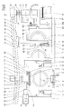
- the Fig. 1 and 2 show an apparatus for producing pipes of thermoplastic material with transverse profiling.
- This device has a base plate 1, on which a molding section 2 is located.
- On this mold section 2 form sections 3 are strung together, each consisting of two mold section halves 4, 5.
- a lower drive pinion 8 is provided immediately behind a spray head 7 of an extruder 8, which protrudes through a recess 9 in the base plate 1 and in a at the respective bottom of the Form section halves 4, 5 trained tooth profile 10 engages.
- the lower drive pinion 8 is rotatably mounted on a drive shaft 11 which is mounted below the base plate 1 and is driven by a transmission motor, not shown.
- the mold section halves 4, 5 are guided or held together on the molding section 2 by guide strips 12, 13 which engage in the region of the mold section halves 4, 5 adjacent to the base plate 1.
- an abutment 14 is provided above the base plate 1 and above the mold.
- This has a base plate 15 on which an upper drive pinion 16 is mounted.
- This upper drive pinion 16 is also rotatably mounted on a drive shaft 17 which is mounted on both sides in bearings 18, 19 which are mounted on the base plate 15.
- the drive shaft 17 is driven by a transmission motor 20 which is attached to the adjacent bearing 18.
- support rollers 21 are mounted with horizontal axis of rotation 22, which are supported on formed on the top of each mold section half 4, 5 support surfaces 23, whereby the position of the abutment 14 to the mold section halves 4, 5 is defined.
- guide rollers 24 are further mounted with a vertical axis of rotation 25 which engage laterally on guide surfaces 26, which are also formed on the upper side of the mold section halves 4, 5.
- the upper drive pinion 16 engages between the support surfaces 23 and the guide surfaces 26 in a tooth profile 27, which is formed on the upper sides of the mold portion halves 4, 5.
- About the upper drive pinion 16 is only 1/3 to 1/4 of the amount of feed force transmitted to the mold sections 3, which is exerted by the lower drive pinion 8 on the mold sections 3.
- the counter-bearing 14 is mounted in mounted on the base plate 1, vertically supported by this upstanding torque supports 28, which absorb the torque exerted by the transmission motor 20 to the counter-bearing 14.
- the counter-bearing 14 itself is essentially due to its own weight on the support surfaces 23. This self-weight is also sufficient to compensate for the forces acting on the engagement of the upper drive pinion 16 in the tooth profile 27, vertically acting upwards on the abutment 14 forces.
- a transport device 29 for the mold section halves 4, 5 is provided above the base plate 1.
- This transport device 29 is constructed in the manner of a bridge crane. It has two parallel to the transport direction 6, the central longitudinal axis 30 of the mold sections 3 and the base plate 1 and mutually parallel guide rails 31, 32. These are arranged above the counter-bearing 14 and supported by supports 33 relative to the base plate 1.
- a transport bridge 34 is supported by run carriage 35. The displacement of the transport bridge 34 on the guide rails 31, 32 by means of linear drives 36, which are formed in the specific embodiment as a spindle drives.
- These linear drives 36 consequently have threaded spindles 37 arranged on the guide rails 31, 32, on which threaded nuts 38 are arranged, which in turn are fastened to the run carriage 35.
- the threaded spindles 37 are each driven via a geared motor 39, 40, wherein these both transmission motors 39, 40 are positively synchronized via a horizontal and transversely to the guide rails 31, 32 extending dome shaft 41.
- the two threaded spindles 37 are thus driven exactly the same speed, so that the transport bridge 34 is moved without tilting on the guide rails 31, 32.
- the transport bridge 34 has two bridge sections 42, 43 which, viewed in each case from the guide rails 31, 32, extend inclined toward one another towards the base plate 1.
- a transport carriage 44, 45 is arranged movably on the two bridge sections 42, 43 and is displaceable in the respective travel direction 46 or 47 by means of a linear drive 48 or 49.
- These linear drives 48, 49 essentially consist in each case of a threaded spindle 50 which is mounted in the respective bridge section 42 or 43 and which engages in a threaded nut 51 on the respective transport carriage 44 or 45.
- the two threaded spindles 50 are driven by a common geared motor 52.
- the gear motors 39, 40 and the gear motor 52 are reversible motors, so suitable for forward and reverse.
- a transport arm 53 is mounted in each case, which extends vertically downwards.
- a holding device 54 for a mold section half 4 or 5 is attached on each transport arm 53.
- a holding abutment 55 is formed on each transport arm 53.
- Each holding device 54 has an upper abutment 56, against which a retaining abutment 55 is pressed from below.
- the holding device 54 further includes a clamping device 57, which consists essentially of a pneumatic or hydraulic piston-cylinder drive 58.
- a Locking pin 60 is formed, which engages with a corresponding actuation of the drive 58 in a locking recess 61 on the underside of the retaining abutment 55 and at the same time presses the abutment 55 against the system 56.
- the holding device 54 is firmly locked to the retaining abutment 55 of the adjacent mold section half 4 and 5 respectively; the latter is thus firmly connected to the transport arm 53.
- Proximity switches 62, 63, 63a, 64 are arranged on the guide rails 31, 32, which signals, as the transport bridge 34 approaches, deliver their signals to a central control, which is not shown.
- Proximity switches 65, 66 are likewise attached to the transport bridge 34, which output an inner or an outer position of the respective transport carriage 44, 45 to the central control unit.
- the mode of action is as follows:
- the form consisting of the mold sections 3 moves in the direction of production 6.
- the tube 68 produced in it moves along at the same speed.
- the two form section 3 forming mold section halves 4, 5 are taken transversely to the production direction 6 from the forming section 2. This happens - as in Fig. 1 is shown by dashed lines - by means of the transport carriage 44, 45 formed with transport arms 53 cross conveyors.
- the transport bridge 34 is speeded along during the last short distance of the last in the production direction 6 mold section 3 with this, wherein the two transport carriage 44, 45 were moved into their adjacent position. In this position, the holding devices 54 have been locked to the retaining abutments 55 of the two mold section halves 4, 5.
- the two transport carriage 44, 45 Upon reaching the downstream end 70, the two transport carriage 44, 45 moved apart due to a corresponding signal of the proximity switch 63, for which purpose the transmission motor 52 is driven accordingly. Due to the inclination of the two bridge sections 42, 43, the mold section halves 4, 5 held on the transport arms 53 are lifted off the base plate 1 and moved outward without friction. When the transport carriages 44 reach the outer proximity switches 66, they are stopped. The gear motors 39, 40 are activated, so that the transport bridge 34 is moved counter to the production direction 6 to the upstream end 67 of the forming section 2. Even with this transport of the mold section halves 4, 5 against the production direction 6, these are not in contact with the base plate 1, but are located above this without friction. They are always moved in parallel to themselves.
- the gear motors 39, 40 Upon reaching the upstream proximity switch 62, the gear motors 39, 40 are stopped, so that the transport bridge 34 is stationary.
- the transmission motor 52 is switched on and moves the Transport carriage 44, 45 inwardly toward the mold section and introduces the two mold section halves 4, 5 at the upstream end 67 transversely to the production direction 6 in the forming section 2, as in Fig. 1 and 2 is shown pulled out.
- the mold section halves 4, 5 lowered back to the base plate 1 down on which they come to rest when the two mold section halves 4, 5 a mold section 3 touch each other, as in Fig. 2 is shown.
- the transport bridge 34 is moved in the production direction 6 until the two already form a section 3 forming section halves 4, 5 come to the leading in the production direction 6 mold section halves 4, 5 to the system and detected by the drive pinions 8 and 16 and further promoted. Then the tensioning devices 57 are released and the transport arms 53 each again moved away from the molding path to the outside. The transport bridge 34 is then again moved to the downstream end 70, as previously described.
- Forming halves 4a, 5a for forming an additional mold section 3a are additionally used on the device described so far for the production of pipes 68, namely because sleeves 71 are to be formed at predetermined intervals in the pipe 68 to be produced endlessly, as is apparent from FIGS EP 0 563 575 A1 (corresponding U.S. Patent 5,320,797 ) is known.
- the additional - form section halves 4a, 5a are in the illustrated embodiment - related to the production direction 6 - downstream of the downstream end 70 of the forming section 2 in a parking position 72 on the base plate 1. Alternatively, the respective parking position 72 also between the upstream end 67 and the downstream end 70 are located.
- She can also - like from the EP 1 216 126 B1 is known - located at the upstream end 67.
- the transport bridge 34 can be moved.
- the parking position 72 is formed in each case by a base 73 on the base plate 1, whose height above the base plate 1 results from the inclination of the bridge sections 42, 43.
- the base 73 is in each case so high that the respective mold section half 4a or 5a in the assigned position of the transport arms 53 carrying them is seated on this base 73.
- This parking position 72, the proximity switch 64 are assigned to the guide rails 31, 32.
- the transport bridge 34 is moved to the parking position 72, and there is a locking of the additional mold section halves 4a, 5a with the transport arms 53 of the transport carriage 44, 45th Then takes place the transport counter to the production direction 6 in the manner already described until the two additional mold section halves 4a, 5a are introduced at the upstream end 67 in the mold section 2.
- proximity switches 63 instead of the proximity switches 63 in the production direction 6 downstream offset proximity switches 63a are used, which have the function of the proximity switch 63.
- the additional mold section halves 4a, 5a need not be included in the circulation of the mold section halves 4, 5; they can be returned to their parking position 72 after each passage through the forming section 2 and can only be used again at a later time. This depends exclusively on how long the forming section 2 and how long the pipe sections should be, each of which a sleeve 71 is assigned.
- the spray head 7 has an inner nozzle 74 and an outer nozzle 75 from which are extruded two heat plastic plastic hoses, namely, an inner tube 76 and an outer tube 77, each of which, after being formed and welded together, comprise a corrugated outer tube 69 and a smooth inner Pipe 78 existing composite pipe 68 form.
- the inner tube 76 and the outer tube 77 are widened and welded together over the entire surface to form the sleeve 71.
- the inner tube 76 is guided in the mold sections 3 via a cooling mandrel 79 mounted on the spray head 7 and arranged downstream of the nozzles 74, 75 in the direction of production 6.
- the inner tube 76 is calibrated and cooled, so solidified.
- the cooling of the outer tube 77 and thus its solidification to the outer tube 69 is carried out primarily via the generally cooled with water mold section halves 4,5.
- Fig. 1 and Fig. 3 gives the parking positions 72 for the mold section halves 4a and 5a respectively associated with a tempering station 80, which in the embodiment of the Fig. 1 and 3 in each case one on a carriage 81 transversely to the production direction 6 to the parked on the base 73 form section half 4a and 5a movable supply line 82 for a liquid temperature control medium and a discharge line 83rd for this medium.
- the lines 82, 83 are provided with couplings 84 which are engageable with counter-couplings 85 on the mold section halves 4a and 5a in tight engagement.
- the counter-couplings 85 are located at the beginning and end of a tempering channel 86 formed in the respective mold section half 4a and 5a, respectively, which is formed independently of a cooling channel formed in all the mold section halves 4, 5, 4a, 5a.
- a tempering medium in particular as a cooling medium, water is suitably used.
- the carriage 81 is moved by means of a linear motor 87 between two end positions, one of which in the Fig. 1 and 3 is shown.
- a linear motor 87 may be, for example, a rodless hydraulic or pneumatic cylinder.
- the control is performed by the control of the entire device, not shown, wherein this control is incorporated into the transport of the mold section halves 4a, 5a in the parking position 72 or out of this parking position 72 out.
- Fig. 5 are formed in the mold section halves 4b no tempering channels.
- carriage 81 is provided, on each of which a cooling plate 89 is mounted, which can be applied over the full surface of the tempering station 80b facing the outer side wall 90 of the respective Formabitesshdeck 4b, so that a good heat flow from the existing metal mold section half 4b on the also made of metal cooling plate 89 takes place.
- a tempering channel 86 b is formed, which in the same manner as in the embodiment of Fig. 3 to a feed line 82 and a discharge line 83 for a flowable Cooling medium, so usually cooling water, is connected.
- the remaining configuration of the temperature control station 80b corresponds to that of the temperature control station 80.
Landscapes
- Engineering & Computer Science (AREA)
- Mechanical Engineering (AREA)
- Manufacturing & Machinery (AREA)
- Physics & Mathematics (AREA)
- Thermal Sciences (AREA)
- Extrusion Moulding Of Plastics Or The Like (AREA)
Applications Claiming Priority (1)
| Application Number | Priority Date | Filing Date | Title |
|---|---|---|---|
| DE102009038547A DE102009038547A1 (de) | 2009-08-22 | 2009-08-22 | Vorrichtung zur Herstellung von außen gewellten Rohren mit Muffen |
Publications (2)
| Publication Number | Publication Date |
|---|---|
| EP2286979A1 true EP2286979A1 (fr) | 2011-02-23 |
| EP2286979B1 EP2286979B1 (fr) | 2013-04-03 |
Family
ID=43332328
Family Applications (1)
| Application Number | Title | Priority Date | Filing Date |
|---|---|---|---|
| EP10168593A Not-in-force EP2286979B1 (fr) | 2009-08-22 | 2010-07-06 | Dispositif de fabrication de tubes ondulés de l'extérieur et dotés de manchons |
Country Status (2)
| Country | Link |
|---|---|
| EP (1) | EP2286979B1 (fr) |
| DE (1) | DE102009038547A1 (fr) |
Cited By (2)
| Publication number | Priority date | Publication date | Assignee | Title |
|---|---|---|---|---|
| CN114834017A (zh) * | 2022-05-19 | 2022-08-02 | 青岛亚森特机械有限公司 | 帽檐芯成型剪裁生产线挤出冷却装置 |
| CN117885262A (zh) * | 2024-03-13 | 2024-04-16 | 福建同盛管业有限公司 | 一种基于hdpe双壁波纹管的加工成型设备及方法 |
Citations (7)
| Publication number | Priority date | Publication date | Assignee | Title |
|---|---|---|---|---|
| EP0563575A2 (fr) | 1992-03-31 | 1993-10-06 | Wilhelm Hegler | Procédé et dispositif de production en continu d'un tube composite avec manchon |
| EP0679498A1 (fr) * | 1994-04-29 | 1995-11-02 | Wilhelm Hegler | Dispositif pour la fabrication de tubes ondulés en matière thermoplastique |
| EP0764516A2 (fr) * | 1995-09-22 | 1997-03-26 | Hegler, Ralph-Peter, Dr.-Ing. | Dispositif pour la fabrication de tuyaux transversalement ondulés en matière thermoplastique |
| DE19914974A1 (de) | 1999-04-01 | 2000-10-12 | Kirchner Fraenk Rohr | Wechselcorrugator |
| DE10006380A1 (de) * | 2000-02-12 | 2001-08-16 | Ralph Peter Hegler | Vorrichtung zur Herstellung von profilierten Kunststoff-Rohren |
| EP1216126B1 (fr) | 1999-09-29 | 2003-06-18 | UNICOR GmbH Rahn Plastmaschinen | Dispositif permettant de fabriquer des tubes a parois profilees transversalement |
| DE10257363C1 (de) * | 2002-12-09 | 2003-10-23 | Unicor Rohrsysteme Gmbh | Formbackenhälfte für eine Vorrichtung zur Erstellung von Querrippenrohren |
Family Cites Families (2)
| Publication number | Priority date | Publication date | Assignee | Title |
|---|---|---|---|---|
| DE2537184C2 (de) * | 1975-08-21 | 1984-06-07 | Ziegelwerke Heinrich Oltmanns, 2905 Edewecht | Anlage zur kontinuierlichen Herstellung von Kunststoffrohren |
| CA1083766A (fr) * | 1977-02-07 | 1980-08-19 | Gerd P.H. Lupke | Appareil servant a la fabrication de tubes thermoplastiques |
-
2009
- 2009-08-22 DE DE102009038547A patent/DE102009038547A1/de not_active Withdrawn
-
2010
- 2010-07-06 EP EP10168593A patent/EP2286979B1/fr not_active Not-in-force
Patent Citations (11)
| Publication number | Priority date | Publication date | Assignee | Title |
|---|---|---|---|---|
| EP0563575A2 (fr) | 1992-03-31 | 1993-10-06 | Wilhelm Hegler | Procédé et dispositif de production en continu d'un tube composite avec manchon |
| US5320797A (en) | 1992-03-31 | 1994-06-14 | Wilhelm Hegler | Method and apparatus for the continuous manufacture of a compound pipe with a pipe socket |
| US5320797B1 (en) | 1992-03-31 | 1997-04-08 | Wilhelm Hegler | Method and apparatus for the continuous manufacture of a compound pipe with a pipe socket |
| EP0679498A1 (fr) * | 1994-04-29 | 1995-11-02 | Wilhelm Hegler | Dispositif pour la fabrication de tubes ondulés en matière thermoplastique |
| EP0764516A2 (fr) * | 1995-09-22 | 1997-03-26 | Hegler, Ralph-Peter, Dr.-Ing. | Dispositif pour la fabrication de tuyaux transversalement ondulés en matière thermoplastique |
| US5693347A (en) | 1995-09-22 | 1997-12-02 | Hegler Ralph Peter | Apparatus for the manufacture of pipes of thermoplastic plastics having transverse profile features |
| EP0764516B1 (fr) | 1995-09-22 | 2001-03-07 | Ralph-Peter Dr.-Ing. Hegler | Dispositif pour la fabrication de tuyaux transversalement ondulés en matière thermoplastique |
| DE19914974A1 (de) | 1999-04-01 | 2000-10-12 | Kirchner Fraenk Rohr | Wechselcorrugator |
| EP1216126B1 (fr) | 1999-09-29 | 2003-06-18 | UNICOR GmbH Rahn Plastmaschinen | Dispositif permettant de fabriquer des tubes a parois profilees transversalement |
| DE10006380A1 (de) * | 2000-02-12 | 2001-08-16 | Ralph Peter Hegler | Vorrichtung zur Herstellung von profilierten Kunststoff-Rohren |
| DE10257363C1 (de) * | 2002-12-09 | 2003-10-23 | Unicor Rohrsysteme Gmbh | Formbackenhälfte für eine Vorrichtung zur Erstellung von Querrippenrohren |
Cited By (3)
| Publication number | Priority date | Publication date | Assignee | Title |
|---|---|---|---|---|
| CN114834017A (zh) * | 2022-05-19 | 2022-08-02 | 青岛亚森特机械有限公司 | 帽檐芯成型剪裁生产线挤出冷却装置 |
| CN117885262A (zh) * | 2024-03-13 | 2024-04-16 | 福建同盛管业有限公司 | 一种基于hdpe双壁波纹管的加工成型设备及方法 |
| CN117885262B (zh) * | 2024-03-13 | 2024-05-31 | 福建同盛管业有限公司 | 一种基于hdpe双壁波纹管的加工成型设备及方法 |
Also Published As
| Publication number | Publication date |
|---|---|
| DE102009038547A1 (de) | 2011-02-24 |
| EP2286979B1 (fr) | 2013-04-03 |
Similar Documents
| Publication | Publication Date | Title |
|---|---|---|
| EP0764516B1 (fr) | Dispositif pour la fabrication de tuyaux transversalement ondulés en matière thermoplastique | |
| EP1243400B1 (fr) | Dispostif pour produire des tuyaux ondulés | |
| EP0636462B1 (fr) | Dispositif pour la fabrication de tubes ondulés en matière thermoplastique | |
| EP0007556A1 (fr) | Dispositif pour la fabrication de tuyaux transversalement ondulés en matière thermoplastique | |
| DE102004040019B4 (de) | Vorrichtung zur Herstellung von Wellrohren | |
| EP0679498B1 (fr) | Dispositif pour la fabrication de tubes ondulés en matière thermoplastique | |
| DE19914974C2 (de) | Wechselcorrugator | |
| EP2200804B1 (fr) | Dispositif pour fabriquer des tubes ondulés thermoplastiques | |
| EP2045068B1 (fr) | Procédé et dispositif de fabrication de tuyaux en plastique thermoplastique dotés d'un profilage transversal | |
| EP0580984B1 (fr) | Dispositif pour la fabrication d'un tuyau à parois ondulées | |
| EP2286979B1 (fr) | Dispositif de fabrication de tubes ondulés de l'extérieur et dotés de manchons | |
| EP1238780B1 (fr) | Procédé et dispositif pour la fabrication de tuyaux transversalement ondulés en matière thermoplastique | |
| DE10235151B4 (de) | Haltevorrichtung für eine Extrusionsdüse | |
| EP0246398B1 (fr) | Dispositif de changement de moule pour un groupe de machine à injecter les matières plastiques | |
| EP3790729B1 (fr) | Dispositif et procédé de moulage par soufflage continu de profilés creux thermoplastiques, renforcés par des fibres, ayant une section transversale constante ou variable | |
| WO2014153676A1 (fr) | Dispositif d'introduction de plastique liquide dans un outil à étages | |
| DE102009035040B4 (de) | Verfahren zur fortlaufenden Herstellung eines Rohres und Vorrichtung zur Durchführung des Verfahrens | |
| DE3118932A1 (de) | Vorrichtung zur herstellung von kunststoffrohren mit querrillen | |
| DE19619429A1 (de) | Teile einer Maschine zur kontinuierlichen Herstellung von radial- oder spiralförmig profilierten Rohren aus thermoplastischen Kunststoffen nach dem Blasformverfahren | |
| DE2058591A1 (de) | Vorrichtung zum Herstellen thermoplastischer Behaelter | |
| DE102006006244B4 (de) | Blasmaschine mit zwei Schließeinheiten | |
| DE102007049655A1 (de) | Korrugatoreinrichtung mit Entformungseinrichtung | |
| DE1479449B1 (de) | Vorrichtung zum herstellen von hohlkoerpern aus thermo plastischen kunststoffen im blasverfahren | |
| CH594492A5 (en) | High speed plastics tube corrugator | |
| DE19700978A1 (de) | Verfahren und Vorrichtung zur kontinuierlichen Herstellung eines Wabenmaterialblocks |
Legal Events
| Date | Code | Title | Description |
|---|---|---|---|
| PUAI | Public reference made under article 153(3) epc to a published international application that has entered the european phase |
Free format text: ORIGINAL CODE: 0009012 |
|
| AK | Designated contracting states |
Kind code of ref document: A1 Designated state(s): AL AT BE BG CH CY CZ DE DK EE ES FI FR GB GR HR HU IE IS IT LI LT LU LV MC MK MT NL NO PL PT RO SE SI SK SM TR |
|
| AX | Request for extension of the european patent |
Extension state: BA ME RS |
|
| 17P | Request for examination filed |
Effective date: 20110806 |
|
| GRAP | Despatch of communication of intention to grant a patent |
Free format text: ORIGINAL CODE: EPIDOSNIGR1 |
|
| RIC1 | Information provided on ipc code assigned before grant |
Ipc: B29C 49/04 20060101ALN20121030BHEP Ipc: B29C 49/00 20060101ALN20121030BHEP Ipc: B29C 33/04 20060101ALN20121030BHEP Ipc: B29C 47/88 20060101ALI20121030BHEP Ipc: B29C 49/48 20060101AFI20121030BHEP Ipc: B29C 47/12 20060101ALN20121030BHEP |
|
| GRAS | Grant fee paid |
Free format text: ORIGINAL CODE: EPIDOSNIGR3 |
|
| GRAA | (expected) grant |
Free format text: ORIGINAL CODE: 0009210 |
|
| AK | Designated contracting states |
Kind code of ref document: B1 Designated state(s): AL AT BE BG CH CY CZ DE DK EE ES FI FR GB GR HR HU IE IS IT LI LT LU LV MC MK MT NL NO PL PT RO SE SI SK SM TR |
|
| REG | Reference to a national code |
Ref country code: GB Ref legal event code: FG4D Free format text: NOT ENGLISH |
|
| REG | Reference to a national code |
Ref country code: AT Ref legal event code: REF Ref document number: 604418 Country of ref document: AT Kind code of ref document: T Effective date: 20130415 Ref country code: CH Ref legal event code: EP |
|
| REG | Reference to a national code |
Ref country code: IE Ref legal event code: FG4D Free format text: LANGUAGE OF EP DOCUMENT: GERMAN |
|
| REG | Reference to a national code |
Ref country code: DE Ref legal event code: R096 Ref document number: 502010002833 Country of ref document: DE Effective date: 20130606 |
|
| PG25 | Lapsed in a contracting state [announced via postgrant information from national office to epo] |
Ref country code: SI Free format text: LAPSE BECAUSE OF FAILURE TO SUBMIT A TRANSLATION OF THE DESCRIPTION OR TO PAY THE FEE WITHIN THE PRESCRIBED TIME-LIMIT Effective date: 20130403 |
|
| REG | Reference to a national code |
Ref country code: NL Ref legal event code: VDEP Effective date: 20130403 |
|
| REG | Reference to a national code |
Ref country code: LT Ref legal event code: MG4D |
|
| PG25 | Lapsed in a contracting state [announced via postgrant information from national office to epo] |
Ref country code: IS Free format text: LAPSE BECAUSE OF FAILURE TO SUBMIT A TRANSLATION OF THE DESCRIPTION OR TO PAY THE FEE WITHIN THE PRESCRIBED TIME-LIMIT Effective date: 20130803 Ref country code: GR Free format text: LAPSE BECAUSE OF FAILURE TO SUBMIT A TRANSLATION OF THE DESCRIPTION OR TO PAY THE FEE WITHIN THE PRESCRIBED TIME-LIMIT Effective date: 20130704 Ref country code: ES Free format text: LAPSE BECAUSE OF FAILURE TO SUBMIT A TRANSLATION OF THE DESCRIPTION OR TO PAY THE FEE WITHIN THE PRESCRIBED TIME-LIMIT Effective date: 20130714 Ref country code: NO Free format text: LAPSE BECAUSE OF FAILURE TO SUBMIT A TRANSLATION OF THE DESCRIPTION OR TO PAY THE FEE WITHIN THE PRESCRIBED TIME-LIMIT Effective date: 20130703 Ref country code: LT Free format text: LAPSE BECAUSE OF FAILURE TO SUBMIT A TRANSLATION OF THE DESCRIPTION OR TO PAY THE FEE WITHIN THE PRESCRIBED TIME-LIMIT Effective date: 20130403 Ref country code: PT Free format text: LAPSE BECAUSE OF FAILURE TO SUBMIT A TRANSLATION OF THE DESCRIPTION OR TO PAY THE FEE WITHIN THE PRESCRIBED TIME-LIMIT Effective date: 20130805 Ref country code: NL Free format text: LAPSE BECAUSE OF FAILURE TO SUBMIT A TRANSLATION OF THE DESCRIPTION OR TO PAY THE FEE WITHIN THE PRESCRIBED TIME-LIMIT Effective date: 20130403 Ref country code: FI Free format text: LAPSE BECAUSE OF FAILURE TO SUBMIT A TRANSLATION OF THE DESCRIPTION OR TO PAY THE FEE WITHIN THE PRESCRIBED TIME-LIMIT Effective date: 20130403 Ref country code: SE Free format text: LAPSE BECAUSE OF FAILURE TO SUBMIT A TRANSLATION OF THE DESCRIPTION OR TO PAY THE FEE WITHIN THE PRESCRIBED TIME-LIMIT Effective date: 20130403 |
|
| PG25 | Lapsed in a contracting state [announced via postgrant information from national office to epo] |
Ref country code: HR Free format text: LAPSE BECAUSE OF FAILURE TO SUBMIT A TRANSLATION OF THE DESCRIPTION OR TO PAY THE FEE WITHIN THE PRESCRIBED TIME-LIMIT Effective date: 20130403 Ref country code: PL Free format text: LAPSE BECAUSE OF FAILURE TO SUBMIT A TRANSLATION OF THE DESCRIPTION OR TO PAY THE FEE WITHIN THE PRESCRIBED TIME-LIMIT Effective date: 20130403 Ref country code: LV Free format text: LAPSE BECAUSE OF FAILURE TO SUBMIT A TRANSLATION OF THE DESCRIPTION OR TO PAY THE FEE WITHIN THE PRESCRIBED TIME-LIMIT Effective date: 20130403 Ref country code: CY Free format text: LAPSE BECAUSE OF FAILURE TO SUBMIT A TRANSLATION OF THE DESCRIPTION OR TO PAY THE FEE WITHIN THE PRESCRIBED TIME-LIMIT Effective date: 20130403 Ref country code: BG Free format text: LAPSE BECAUSE OF FAILURE TO SUBMIT A TRANSLATION OF THE DESCRIPTION OR TO PAY THE FEE WITHIN THE PRESCRIBED TIME-LIMIT Effective date: 20130703 |
|
| BERE | Be: lapsed |
Owner name: HEGLER, RALPH PETER Effective date: 20130731 |
|
| PG25 | Lapsed in a contracting state [announced via postgrant information from national office to epo] |
Ref country code: SK Free format text: LAPSE BECAUSE OF FAILURE TO SUBMIT A TRANSLATION OF THE DESCRIPTION OR TO PAY THE FEE WITHIN THE PRESCRIBED TIME-LIMIT Effective date: 20130403 Ref country code: CZ Free format text: LAPSE BECAUSE OF FAILURE TO SUBMIT A TRANSLATION OF THE DESCRIPTION OR TO PAY THE FEE WITHIN THE PRESCRIBED TIME-LIMIT Effective date: 20130403 Ref country code: DK Free format text: LAPSE BECAUSE OF FAILURE TO SUBMIT A TRANSLATION OF THE DESCRIPTION OR TO PAY THE FEE WITHIN THE PRESCRIBED TIME-LIMIT Effective date: 20130403 Ref country code: EE Free format text: LAPSE BECAUSE OF FAILURE TO SUBMIT A TRANSLATION OF THE DESCRIPTION OR TO PAY THE FEE WITHIN THE PRESCRIBED TIME-LIMIT Effective date: 20130403 |
|
| PLBE | No opposition filed within time limit |
Free format text: ORIGINAL CODE: 0009261 |
|
| STAA | Information on the status of an ep patent application or granted ep patent |
Free format text: STATUS: NO OPPOSITION FILED WITHIN TIME LIMIT |
|
| PG25 | Lapsed in a contracting state [announced via postgrant information from national office to epo] |
Ref country code: IT Free format text: LAPSE BECAUSE OF FAILURE TO SUBMIT A TRANSLATION OF THE DESCRIPTION OR TO PAY THE FEE WITHIN THE PRESCRIBED TIME-LIMIT Effective date: 20130403 Ref country code: MC Free format text: LAPSE BECAUSE OF FAILURE TO SUBMIT A TRANSLATION OF THE DESCRIPTION OR TO PAY THE FEE WITHIN THE PRESCRIBED TIME-LIMIT Effective date: 20130403 Ref country code: RO Free format text: LAPSE BECAUSE OF FAILURE TO SUBMIT A TRANSLATION OF THE DESCRIPTION OR TO PAY THE FEE WITHIN THE PRESCRIBED TIME-LIMIT Effective date: 20130403 |
|
| 26N | No opposition filed |
Effective date: 20140106 |
|
| REG | Reference to a national code |
Ref country code: DE Ref legal event code: R097 Ref document number: 502010002833 Country of ref document: DE Effective date: 20140106 |
|
| REG | Reference to a national code |
Ref country code: IE Ref legal event code: MM4A |
|
| PG25 | Lapsed in a contracting state [announced via postgrant information from national office to epo] |
Ref country code: BE Free format text: LAPSE BECAUSE OF NON-PAYMENT OF DUE FEES Effective date: 20130731 |
|
| PG25 | Lapsed in a contracting state [announced via postgrant information from national office to epo] |
Ref country code: IE Free format text: LAPSE BECAUSE OF NON-PAYMENT OF DUE FEES Effective date: 20130706 |
|
| REG | Reference to a national code |
Ref country code: CH Ref legal event code: PL |
|
| PG25 | Lapsed in a contracting state [announced via postgrant information from national office to epo] |
Ref country code: LI Free format text: LAPSE BECAUSE OF NON-PAYMENT OF DUE FEES Effective date: 20140731 Ref country code: CH Free format text: LAPSE BECAUSE OF NON-PAYMENT OF DUE FEES Effective date: 20140731 |
|
| PG25 | Lapsed in a contracting state [announced via postgrant information from national office to epo] |
Ref country code: SM Free format text: LAPSE BECAUSE OF FAILURE TO SUBMIT A TRANSLATION OF THE DESCRIPTION OR TO PAY THE FEE WITHIN THE PRESCRIBED TIME-LIMIT Effective date: 20130403 |
|
| PG25 | Lapsed in a contracting state [announced via postgrant information from national office to epo] |
Ref country code: MT Free format text: LAPSE BECAUSE OF FAILURE TO SUBMIT A TRANSLATION OF THE DESCRIPTION OR TO PAY THE FEE WITHIN THE PRESCRIBED TIME-LIMIT Effective date: 20130403 Ref country code: TR Free format text: LAPSE BECAUSE OF FAILURE TO SUBMIT A TRANSLATION OF THE DESCRIPTION OR TO PAY THE FEE WITHIN THE PRESCRIBED TIME-LIMIT Effective date: 20130403 |
|
| PG25 | Lapsed in a contracting state [announced via postgrant information from national office to epo] |
Ref country code: MK Free format text: LAPSE BECAUSE OF FAILURE TO SUBMIT A TRANSLATION OF THE DESCRIPTION OR TO PAY THE FEE WITHIN THE PRESCRIBED TIME-LIMIT Effective date: 20130403 Ref country code: HU Free format text: LAPSE BECAUSE OF FAILURE TO SUBMIT A TRANSLATION OF THE DESCRIPTION OR TO PAY THE FEE WITHIN THE PRESCRIBED TIME-LIMIT; INVALID AB INITIO Effective date: 20100706 Ref country code: LU Free format text: LAPSE BECAUSE OF NON-PAYMENT OF DUE FEES Effective date: 20130706 |
|
| REG | Reference to a national code |
Ref country code: FR Ref legal event code: PLFP Year of fee payment: 7 |
|
| REG | Reference to a national code |
Ref country code: AT Ref legal event code: MM01 Ref document number: 604418 Country of ref document: AT Kind code of ref document: T Effective date: 20150706 |
|
| PGFP | Annual fee paid to national office [announced via postgrant information from national office to epo] |
Ref country code: GB Payment date: 20160722 Year of fee payment: 7 |
|
| PG25 | Lapsed in a contracting state [announced via postgrant information from national office to epo] |
Ref country code: AT Free format text: LAPSE BECAUSE OF NON-PAYMENT OF DUE FEES Effective date: 20150706 |
|
| PGFP | Annual fee paid to national office [announced via postgrant information from national office to epo] |
Ref country code: FR Payment date: 20160722 Year of fee payment: 7 |
|
| PGFP | Annual fee paid to national office [announced via postgrant information from national office to epo] |
Ref country code: DE Payment date: 20170925 Year of fee payment: 8 |
|
| GBPC | Gb: european patent ceased through non-payment of renewal fee |
Effective date: 20170706 |
|
| REG | Reference to a national code |
Ref country code: FR Ref legal event code: ST Effective date: 20180330 |
|
| PG25 | Lapsed in a contracting state [announced via postgrant information from national office to epo] |
Ref country code: GB Free format text: LAPSE BECAUSE OF NON-PAYMENT OF DUE FEES Effective date: 20170706 |
|
| PG25 | Lapsed in a contracting state [announced via postgrant information from national office to epo] |
Ref country code: FR Free format text: LAPSE BECAUSE OF NON-PAYMENT OF DUE FEES Effective date: 20170731 |
|
| PG25 | Lapsed in a contracting state [announced via postgrant information from national office to epo] |
Ref country code: AL Free format text: LAPSE BECAUSE OF FAILURE TO SUBMIT A TRANSLATION OF THE DESCRIPTION OR TO PAY THE FEE WITHIN THE PRESCRIBED TIME-LIMIT Effective date: 20130403 |
|
| REG | Reference to a national code |
Ref country code: DE Ref legal event code: R119 Ref document number: 502010002833 Country of ref document: DE |
|
| PG25 | Lapsed in a contracting state [announced via postgrant information from national office to epo] |
Ref country code: DE Free format text: LAPSE BECAUSE OF NON-PAYMENT OF DUE FEES Effective date: 20190201 |