EP2298057B1 - Device for transporting and cleaning harvested goods in the form of root crops, in particular in the form of sugar beets, and cleaning loader with such a device - Google Patents
Device for transporting and cleaning harvested goods in the form of root crops, in particular in the form of sugar beets, and cleaning loader with such a device Download PDFInfo
- Publication number
- EP2298057B1 EP2298057B1 EP10007707A EP10007707A EP2298057B1 EP 2298057 B1 EP2298057 B1 EP 2298057B1 EP 10007707 A EP10007707 A EP 10007707A EP 10007707 A EP10007707 A EP 10007707A EP 2298057 B1 EP2298057 B1 EP 2298057B1
- Authority
- EP
- European Patent Office
- Prior art keywords
- conveyor
- cleaning
- transport
- crops
- operating state
- Prior art date
- Legal status (The legal status is an assumption and is not a legal conclusion. Google has not performed a legal analysis and makes no representation as to the accuracy of the status listed.)
- Active
Links
Images


Classifications
-
- A—HUMAN NECESSITIES
- A01—AGRICULTURE; FORESTRY; ANIMAL HUSBANDRY; HUNTING; TRAPPING; FISHING
- A01D—HARVESTING; MOWING
- A01D33/00—Accessories for digging harvesters
- A01D33/10—Crop collecting devices, with or without weighing apparatus
-
- A—HUMAN NECESSITIES
- A01—AGRICULTURE; FORESTRY; ANIMAL HUSBANDRY; HUNTING; TRAPPING; FISHING
- A01D—HARVESTING; MOWING
- A01D33/00—Accessories for digging harvesters
- A01D33/08—Special sorting and cleaning mechanisms
Definitions
- the invention relates to a device according to the preamble of claim 1 and to a cleaning loader according to the preamble of claim 10.
- Cleaning loader i. Devices for picking up crops in the form of cleared root crops, especially sugar beets from field rents and for transferring the pre-cleaned crop in transport vehicles are known in various designs, especially as self-propelled or non-self-propelled equipment or machinery. It is also known to provide within the formed on the respective cleaning loader transport route for the Rode- or crop a Nachtherapiesumble having at least one feed dog, which is either a transporting the Rodegut and at the same time abrCenterdes screen belt or a Rodegut transporting and at the same time cleaning Zwickelwalzenrillian ie a conveyor, whose transport surface is formed by a plurality of adjacent and oppositely driven cleaning rollers. Depending on the nature of the crop, which depends, among other things, on the weather and soil conditions during harvesting, both types of conveyors or cleaning lines offer advantages and disadvantages.
- the object of the invention is to provide a device for cleaning and transporting crops in the form of root crops, especially sugar beet, show a continuous adjustment of the cleaning intensity of the nature of the crop or the field rental and in particular also to the nature of the contamination of the allows for the respective field rent merged crop.
- a device for transporting and cleaning root crops according to claim 1 is formed.
- a cleaning loader for receiving, cleaning and transferring the crop to the loading area of a transport vehicle is the subject of claim 10.
- the particular advantage of the device according to the invention is that the degree of cleaning or the type of cleaning (by screen belt and / or by Zwickelrillian) and the proportion of each type of cleaning to the entire post-cleaning are infinitely adjustable, between a first extreme operating condition in which the Device exclusively or essentially acts as Siebband- or Siebkettenrillian, and a second extreme operating condition in which the device acts exclusively or substantially only as Zwickelwalzenrillian. Between these two extremes, any combinations are infinitely adjustable, in adaptation to the condition of the crop or to the soil and weather conditions in which the crop was cleared, and this setting can be changed at any time during operation motor.
- the cleaning loader serves to receive harvested crops in the form of sugar beet, e.g. from field rents and to overload the crop on transport vehicles, such as trucks or trailers for further transport, for example, for road transport to a processing in the crop (for example, sugar factory).
- transport vehicles such as trucks or trailers for further transport, for example, for road transport to a processing in the crop (for example, sugar factory).
- the cleaning loader 1 is self-propelled in the illustrated embodiment and consists for this purpose of a vehicle frame 2 with two vehicle axles 3 and 4, of which at least one is steerable and at least one driven by a vehicle drive or motor 5.
- a Ernteguting 6 is provided with the crop picked up on a large width and then merged into a central narrowed Erntegutstrom forwarded to an in-vehicle conveyor 7, with which the crop u.a. is transported under a provided on the front of the vehicle cab 8 through toward the rear of the vehicle.
- the crop or the crop flow formed by this crop passes there to a projecting beyond the rear of the vehicle frame 2 Nachtherapiesumble 9 and from this to a serving as a jib boom or feed dog 10, with which it is introduced into the transport vehicle, not shown.
- the Nachtherapiesumble 9 consists, inter alia, of a frame 11, which extends in the transport direction A, open at the top forming a channel-like conveying path for the crop, which at the two in the direction of transport A extending longitudinal sides by wall sections 12, at the front relative to the transport direction A front or Erntegutankgabe 9.1, inter alia, by the wall section 13 and on the rear side relative to the transport direction A front page or Erntegutabgabe 9.2 is limited, inter alia, by the wall portion 14.
- a plurality of cleaning rollers 15 are rotatably mounted, in such a way that these rollers are oriented with their longitudinal extent in each case in the longitudinal direction of the frame 11 and in the conveying direction A and close together, so that they form a Ernteguttransport simulation a Zwickelwalzenrillian 16 in their entirety, on the (transport surface) the crop when using the Zwickelwalzenranss, ie rests in a more intensive cleaning in the manner described in more detail below.
- the cleaning rollers 15 are provided at their in the illustrated embodiment circular cylindrical outer surface each with a helix or with a worm gear 17, in such a way that the worm gear adjacent cleaning rollers 15 is formed in opposite directions.
- the cleaning rollers 15 are driven during operation of the cleaning loader 1 so that adjacent cleaning rollers 15 each rotate in opposite directions.
- the cleaning rollers 15 of the gusset roller cleaner 16 end with respect to the transport direction A at a distance from the end wall 14, so that in the region of this end wall, a discharge opening 19 is formed, passes through the crop after passing the Nachthesessize 9 on the subsequent below the opening 19 feed dog 10 , As shown in the figures, the gusset roller cleaner 16 extends from the transfer opening 19 against the transport direction A about half or two-thirds of the length of the post-cleaning section 9.
- the frame 11 is open, so that in the subsequent cleaning of the crop cleaned impurities, such as stones, soil, beetroot and weeds may fall on the farmland.
- a screen belt cleaner 20 is further provided with a screen belt 21, which forms a closed loop, as in particular in the FIG. 4 is shown schematically.
- the screen belt 21 consists in the illustrated embodiment essentially of two likewise each a closed loop forming belt 22.1, which also each form a closed loop, the loop planes are oriented parallel to the transport direction A and perpendicular to the transport plane of Nachquelsddle 9, as well as a variety of Bars 22.2, which extend between the two belts 22.1 and Siebbandlteilsraum are spaced apart.
- the screen belt 21 is guided over several Siebbandumlenk Institute 23 - 26, for example in the form of deflection rollers or rollers that it or its loop two overlapping loop portions 21 a and 21 b forms, of which the loop portion 21 a above the loop portion 21st b is provided.
- the transition formed by the Siebbandumlenk Institute 25 and 26 to the loop or Siebbandabterrorismen 21 a and 21 b is provided on the Erntegutaufgabe 9.1 below the local wall 13.
- the upper wire section 21 a is located at a level above the Zwickelwalzenrutzs 16 and the Siebbandabexcellent 21 b at least a partial length at a level below the Zwickelwalzenranss 16th
- the screen belt 21 is driven during operation of the cleaning loader 1 so that the upper loop length of the wire section 21 a, the transport surface of the screen belt cleaner 20 forms, moves in the transport direction A.
- the axes of the Siebbandumlenkitch 23 - 26 are oriented perpendicular to the transport direction A.
- the Siebband deflections 23 and 24 are in the transport direction A or counter to this transport direction in opposite directions adjustable so that the Siebbandrillian 20 and the screen belt 21 is movable like a jalousine over the Zwickelwalzenrillian, between first operating state, in which the upper of the Erntegutankgabe 9.1 outgoing Siebbandabites 21st a covers gusset cleaner 16 over its entire length or over substantially its entire length ( FIG. 2 ) and at the Transfer opening 19 or near this opening ends, and a second operating state in which the screen belt 21 forms a subsequent to the Erntegutiergabe 9.1 and reaching to the gusset cleaner 16 conveying and cleaning section ( FIG. 3 ).
- the screen belt 21 can assume any state between these two extreme operating conditions, i. depending on the requirement of the upper Siebbandabête 21a the gusset roller cleaner 16 can cover more or less.
- the louver-like movement of the screen belt 21 on the frame 11 lateral in the transport direction A or substantially in the direction of transport extending guides 27 are provided for the Siebbandumlenk Institute 23 and 24.
- the screen belt 21 is formed by two belts 22.1 and rods 22.2 extending between these belts.
- the screen belt 21 may also be designed differently and / or instead of the belt 22.1, other belt or belt or chain-like, each forming a closed loop transport elements may be used.
Landscapes
- Life Sciences & Earth Sciences (AREA)
- Environmental Sciences (AREA)
- Harvesting Machines For Root Crops (AREA)
Description
Die Erfindung bezieht sich auf eine Vorrichtung gemäß Oberbegriff Patentanspruch 1 und auf einen Reinigungslader gemäß Oberbegriff Patentanspruch 10.The invention relates to a device according to the preamble of
Eine solche vorrichtung ist durch die
Reinigungslader, d.h. Vorrichtungen zum Aufnehmen von Erntegut in Form von gerodeten Wurzelfrüchten, insbesondere von Zuckerrüben aus Feldmieten sowie zum Überführen des vorgereinigten Erntegutes in Transportfahrzeuge sind in verschiedensten Ausführungen bekannt, insbesondere auch als selbstfahrende oder als nicht selbstfahrende Geräte oder Maschinen. Bekannt ist es auch, innerhalb der an dem jeweiligen Reinigungslader ausgebildeten Transportstrecke für das Rode- oder Erntegut eine Nachreinigungsstrecke vorzusehen, die wenigstens einen Transporteur aufweist, der entweder ein das Rodegut transportierendes und zugleich abreinigendes Siebband oder aber ein das Rodegut transportierender und zugleich abreinigender Zwickelwalzenreiniger ist, d.h. ein Transporteur, dessen Transportfläche von mehreren einander benachbarten und gegenläufig angetriebenen Reinigungswalzen gebildet ist. Abhängig von der Beschaffenheit des Erntegutes, die unter anderem von den Witterungs- und Bodenverhältnissen während des Rodens abhängt, bieten beide Arten von Transporteuren oder Reinigungsstrecken Vor- und Nachteile.Cleaning loader, i. Devices for picking up crops in the form of cleared root crops, especially sugar beets from field rents and for transferring the pre-cleaned crop in transport vehicles are known in various designs, especially as self-propelled or non-self-propelled equipment or machinery. It is also known to provide within the formed on the respective cleaning loader transport route for the Rode- or crop a Nachreinigungsstrecke having at least one feed dog, which is either a transporting the Rodegut and at the same time abreinigendes screen belt or a Rodegut transporting and at the same time cleaning Zwickelwalzenreiniger ie a conveyor, whose transport surface is formed by a plurality of adjacent and oppositely driven cleaning rollers. Depending on the nature of the crop, which depends, among other things, on the weather and soil conditions during harvesting, both types of conveyors or cleaning lines offer advantages and disadvantages.
Mit dem als Siebband ausgebildeten Transporteur ist eine besonders schonende Abreinigung des Erntegutes ohne starke mechanische Belastung möglich, allerdings bei losen anhaftenden Verunreinigungen, wie Erde, Steine usw. Mit dem als Zwickelreiniger ausgebildeten Transporteur ist hingegen eine intensivere Abreinigung des Erntegutes, auch bei intensiver oder fest anhaftenden Verunreinigungen, insbesondere in Form von feuchter Erde, sowie eine Trennung des Erntegutes von Beikraut und Blättern möglich. Der Zwickelreiniger wird daher bevorzugt bei einem Erntegut mit hohem Erdanhang verwendet. Nachteilig ist bei Verwendung des als Zwicketwatzenreiniger ausgebildeten Transporteurs aber eine reduzierte Förderleistung und ein erhöhter Anteil von Bruchverlusten im Erntegut.With the conveyor designed as a conveyor belt, a particularly gentle cleaning of the crop is possible without strong mechanical stress, but with loose adhering contaminants, such as earth, stones, etc. With the trained as Zwickelreiniger conveyor, however, is a more intensive cleaning of the crop, even with intense or solid adhering impurities, especially in the form of moist soil, and a separation of the crop of Beikraut and leaves possible. The gusset cleaner is therefore preferably used in a crop with high Erdanhang. A disadvantage, however, when using the designed as Zwicketwatzenreiniger transporter but a reduced capacity and an increased proportion of breakage losses in the crop.
Aufgabe der Erfindung ist es, eine Vorrichtung zum Reinigen und Transportieren von Erntegut in Form von Wurzelfrüchten, insbesondere Zuckerrüben, aufzuzeigen, die eine stufenlose Anpassung der Reinigungsintensität an die Beschaffenheit des Erntegutes bzw. der jeweiligen Feldmiete und dabei insbesondere auch an die Beschaffenheit der Verunreinigung des zu der jeweiligen Feldmiete zusammengeführten Erntegutes ermöglicht.The object of the invention is to provide a device for cleaning and transporting crops in the form of root crops, especially sugar beet, show a continuous adjustment of the cleaning intensity of the nature of the crop or the field rental and in particular also to the nature of the contamination of the allows for the respective field rent merged crop.
Zur Lösung dieser Aufgabe ist eine Vorrichtung zum Transportieren und Reinigen von Wurzelfrüchten entsprechend dem Patentanspruch 1 ausgebildet. Ein Reinigungslader zum Aufnehmen, Reinigen und Überführen des Erntegutes an die Ladefläche eines Transportfahrzeugs ist Gegenstand des Patentanspruches 10.To solve this problem, a device for transporting and cleaning root crops according to
Der besondere Vorteil der erfindungsgemäßen Vorrichtung besteht darin, dass der Reinigungsgrad bzw. die Reinigungsart (durch Siebband und/oder durch Zwickelreiniger) und der Anteil der jeweiligen Reinigungsart an der gesamten Nachreinigung stufenlos einstellbar sind, und zwar zwischen einem ersten extremen Betriebszustand, in welchem die Vorrichtung ausschließlich oder im wesentlichen als Siebband- oder Siebkettenreiniger wirkt, und einem zweiten extremen Betriebszustand, in welchem die Vorrichtung ausschließlich oder im wesentlichen nur als Zwickelwalzenreiniger wirkt. Zwischen diesen beiden Extremen sind beliebige Kombinationen stufenlos einstellbar, und zwar in Anpassung an den Zustand des Erntegutes bzw. an die Boden- und Witterungsbedingungen bei denen das Erntegut gerodet wurde, wobei diese Einstellung auch während des Betriebes motorisch jederzeit geändert werden kann.The particular advantage of the device according to the invention is that the degree of cleaning or the type of cleaning (by screen belt and / or by Zwickelreiniger) and the proportion of each type of cleaning to the entire post-cleaning are infinitely adjustable, between a first extreme operating condition in which the Device exclusively or essentially acts as Siebband- or Siebkettenreiniger, and a second extreme operating condition in which the device acts exclusively or substantially only as Zwickelwalzenreiniger. Between these two extremes, any combinations are infinitely adjustable, in adaptation to the condition of the crop or to the soil and weather conditions in which the crop was cleared, and this setting can be changed at any time during operation motor.
Weiterbildungen, Vorteile und Anwendungsmöglichkeiten der Erfindung ergeben sich auch aus der nachfolgenden Beschreibung von Ausführungsbeispielen und aus den Figuren. Dabei sind alle beschriebenen und/oder bildlich dargestellten Merkmale für sich oder in beliebiger Kombination grundsätzlich Gegenstand der Erfindung, unabhängig von ihrer Zusammenfassung in den Ansprüchen oder deren Rückbeziehung. Auch wird der Inhalt der Ansprüche zu einem Bestandteil der Beschreibung gemacht.Further developments, advantages and applications of the invention will become apparent from the following description of exemplary embodiments and from the figures. In this case, all described and / or illustrated features alone or in any combination are fundamentally the subject of the invention, regardless of their summary in the claims or their dependency. Also, the content of the claims is made an integral part of the description.
Die Erfindung wird im Folgenden anhand der Figuren an einem Ausführungsbeispiel näher erläutert. Es zeigen:
- Fig. 1
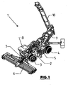
- in perspektivischer Darstellung einen Rübenreinigungslader gemäß der Erfindung;
- Fig. 2 und 3
- in perspektivischer Einzeldarstellung eine Nachreinigungsstrecke des Rübenreinigungsladers der
Figur 1 - Fig. 4
- in vereinfachter schematischer Darstellung den Verlauf des Siebbandes.
- Fig. 1
- in perspective view of a beet cleaning loader according to the invention;
- FIGS. 2 and 3
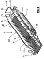
- in a perspective detailed view of a Nachreinigungsstrecke the beet cleaning loader
FIG. 1 ; - Fig. 4
- in a simplified schematic representation of the course of the screen belt.
Der in den Figuren allgemein mit 1 bezeichnete Reinigungslader dient zum Aufnehmen von gerodetem Erntegut in Form von Zuckerrüben z.B. aus Feldmieten und zum Überladen des Erntegutes auf Transportfahrzeuge, beispielsweise auf Lkws oder Anhänger für den Weitertransport, beispielsweise für den Straßentransport zu einem in das Erntegut verarbeitenden Betrieb (beispielsweise Zuckerfabrik).The cleaning loader, indicated generally by 1 in the figures, serves to receive harvested crops in the form of sugar beet, e.g. from field rents and to overload the crop on transport vehicles, such as trucks or trailers for further transport, for example, for road transport to a processing in the crop (for example, sugar factory).
Der Reinigungslader 1 ist bei der dargestellten Ausführungsform selbstfahrend ausgebildet und besteht hierfür aus einem Fahrzeugrahmen 2 mit zwei Fahrzeugachsen 3 und 4, von denen wenigstens eine lenkbar und wenigstens eine durch einen Fahrzeugantrieb oder -Motor 5 angetrieben ist. An der Vorderseite des Fahrzeugrahmens 2 ist eine Erntegutaufnahme 6 vorgesehen, mit der das Erntegut auf großer Breite aufgenommen und dann zu einem mittigen verengten Erntegutstrom zusammengeführt an einen fahrzeuginternen Transporteur 7 weitergeleitet wird, mit welchem das Erntegut u.a. unter einer an der Fahrzeugfrontseite vorgesehenen Fahrerkabine 8 hindurch in Richtung Fahrzeugheck transportiert wird. Das Erntegut bzw. der von diesem Erntegut gebildete Erntegutstrom gelangt dort auf eine über das Heck des Fahrzeugrahmens 2 wegstehende Nachreinigungsstrecke 9 und von dieser auf einen als Überlader dienenden Ausleger oder Transporteur 10, mit dem es in das nicht dargestellte Transportfahrzeug eingebracht wird.The
Eine Besonderheit des Reinigungsladers 1 besteht in der Ausbildung der Nachreinigungsstrecke 9, die in den
Im Rahmen 11 sind mehrere Reinigungswalzen 15 drehbar gelagert, und zwar derart, dass diese Walzen mit ihrer Längserstreckung jeweils in Längsrichtung des Rahmens 11 bzw. in Förderrichtung A orientiert sind und dicht aneinander anschließen, sodass sie in ihrer Gesamtheit eine Ernteguttransportfläche eines Zwickelwalzenreiniger 16 bilden, auf der (Transportfläche) das Erntegut bei Verwendung des Zwickelwalzenreinigers, d.h. bei einer intensiveren Nachreinigung in der nachstehend noch näher beschriebenen Weise aufliegt. Die Reinigungswalzen 15 sind an ihrer bei der dargestellten Ausführungsform kreiszylinderförmigen Außenfläche jeweils mit einer Wendel bzw. mit einem Schneckengang 17 versehen, und zwar derart, dass der Schneckengang benachbarter Reinigungswalzen 15 jeweils gegenläufig ausgebildet ist. Durch einen Antrieb 18 und weitere, nicht dargestellte Getriebeelemente sind die Reinigungswalzen 15 während des Betriebes des Reinigungsladers 1 so angetrieben, dass einander benachbarte Reinigungswalzen 15 jeweils gegenläufig umlaufen.In the
Die Reinigungswalzen 15 des Zwickelwalzenreinigers 16 enden bezogen auf die Transportrichtung A mit Abstand von der Stirnwand 14, sodass im Bereich dieser Stirnwand eine Abgabeöffnung 19 gebildet ist, über die das Erntegut nach dem Passieren der Nachreinigungsstrecke 9 auf den unterhalb der Öffnung 19 anschließenden Transporteur 10 gelangt. Wie in den Figuren dargestellt erstreckt sich der Zwickelwalzenreiniger 16 ausgehend von der Übergabeöffnung 19 entgegen der Transportrichtung A etwa über die Hälfte oder 2/3 Drittel der Länge der Nachreinigungsstrecke 9.The
Unterhalb des Zwickelwalzenreinigers 16 ist der Rahmen 11 offen, sodass bei der Nachreinigung vom Erntegut abgereinigte Verunreinigungen, beispielsweise Steine, Erde, Rüben- und Beikraut usw. auf den Ackerboden fallen kann.Below the
Am Rahmen 1 ist weiterhin ein Siebbandreiniger 20 mit einem Siebband 21 vorgesehen, welches eine geschlossene Schlaufe bildet, wie insbesondere auch in der
Wie insbesondere auch der schematischen Darstellung der
Durch den Antrieb 18 ist das Siebband 21 während des Betriebes des Reinigungsladers 1 so angetrieben, dass die obere Schlaufenlänge des Siebbandabschnittes 21 a, die Transportfläche des Siebbandreinigers 20 bildet, sich in Transportrichtung A bewegt. Die Achsen der Siebbandumlenkungen 23 - 26 sind senkrecht zur Transportrichtung A orientiert.By the
Die Siebbandumlenkungen 23 und 24 sind in Transportrichtung A oder entgegen dieser Transportrichtung gegenläufig derart verstellbar, dass der Siebbandreiniger 20 bzw. das Siebband 21 jalousieartig über dem Zwickelwalzenreiniger bewegbar ist, und zwar zwischen ersten Betriebszustand, in welchem der obere von der Erntegutaufgabe 9.1 ausgehende Siebbandabschnitt 21 a den Zwickelwalzenreiniger 16 auf seiner gesamten Länge oder im Wesentlichen auf seiner gesamten Länge abdeckt (
Es versteht sich, dass das Siebband 21 zwischen diesen beiden extremen Betriebszuständen jeden beliebigen Zustand einnehmen kann, d.h. je nach Erfordernis der oberen Siebbandabschnitte 21a den Zwickelwalzenreiniger 16 mehr oder weniger stark überdecken kann. Für das jalousieartige Bewegen des Siebbandes 21 sind am Rahmen 11 seitliche, sich in Transportrichtung A oder im Wesentlichen in Transportrichtung erstreckende Führungen 27 für die Siebbandumlenkungen 23 und 24 vorgesehen.It is understood that the
Die Vorteile der Nachreinigungsstrecke 9 bestehen u.a. darin, dass auf dem ersten Teil der Förderstrecke zunächst eine schonende Abreinigung des Erntegutes mit dem Siebbandreiniger 20 erfolgt, und zwar unabhängig von der Einstellung des Siebbandes 21. Durch die Einstellung des Siebbandes 21 bzw. der von diesem gebildeten Länge der Förderstrecke ist es möglich, die Arbeitsweise der Nachreinigungsstrecke 9 bzw. deren Reinigungsintensität und/oder -art stufenlos an die jeweiligen Verhältnisse anzupassen. Für eine schonende Abreinigung des Erntegutes befindet sich das Siebband 20 in dem den Zwickelwalzenreiniger 16 vollständig oder nahezu vollständig überdeckenden ersten Betriebszustand, was insbesondere bei trockenem und wenig steinigem Boden möglich ist, und zwar bei geringen Verschleiß der Nachreinigungsstrecke 9 und bei geringem Erntegutbruch. Ist aufgrund der Boden- und Witterungsverhältnisse beim Roden eine intensive Nachreinigung des Erntegutes notwendig, so wird der Siebbandabschnitt 21 a soweit zurückbewegt bzw. verkleinert, sodass der Zwickelwalzenreiniger 16 auf längerem Transportweg zur Wirkung kommt und dadurch intensiver anhaftende Verschmutzungen und Beikraut vom Erntegut entfernt wird, allerdings evtl. mit dem Nachteil höherer Bruchverluste.The advantages of
Die Erfindung wurde voranstehend an einem Ausführungsbeispiel beschrieben. Es versteht sich, dass zahlreiche Änderungen sowie Abwandlungen möglich sind, ohne dass dadurch der der Erfindung zugrundeliegende Erfindungsgedanke verlassen wird. So wurde vorstehen davon ausgegangen, dass der Siebbandreiniger 20 von einem einzigen Siebband gebildet ist. Der Siebbabyreiniger 20 kann aber auch zwei oder mehr als zwei Siebbänder aufweisen.The invention has been described above by means of an embodiment. It is understood that numerous changes and modifications are possible without thereby departing from the inventive concept underlying the invention. Thus, it has been assumed that the
Weiterhin wurde vorstehen davon ausgegangen, dass das Siebband 21 von zwei Riemen 22.1 und von Stäben 22.2 gebildet ist, die sich zwischen diesen Riemen erstrecken. Selbstverständlich kann das Siebband 21 auch anders ausgeführt sein und/oder anstelle der Riemen 22.1 können auch andere band- oder riemen- oder kettenartige, jeweils eine geschlossene Schlaufe bildende Transportelemente verwendet sein.Furthermore, it has been assumed that the
Vorstehend wurde weiterhin auch davon ausgegangen, dass sich die unteren Siebbandlänge 21 b unterhalb der Siebbandlänge 21 a befindet und das Siebband 21 zur stufenlosen Einstellung der Reinigungswirkung der Nachreinigungsstrecke 9 mehr oder weniger weit unter die Reinigungswalzen 15 des Zwickelwalzenreinigers 16 einführbar ist. Wenngleich diese Ausführung den Vorteil hat, dass die Nachreinigungsstrecke 9 als voll funktionsfähige Baueinheit bzw. als vollfunktionsfähiges Modul mit geringen Abmessungen insbesondere auch in der Achse der Transportrichtung A sowie quer zu dieser Achse gefertigt und an dem Fahrzeugrahmen 2 montiert werden kann, sind auch andere Ausführungen denkbar, bei denen das Siebband mit seinem aktuell nicht als Transportebene für das Erntegut genutzten Siebbandabschnitt anderweitig außerhalb der Ernteguttransportstrecke der Nachreinigungsstrecke angeordnet ist, beispielsweise unterhalb eines im Fahrzeugrahmen vorgesehenen Transporteurs.Above was also assumed that the
- 11
- Reinigungsladercleaning loaders
- 22
- Fahrzeugrahmenvehicle frame
- 3,43.4
- Fahrzeugachsevehicle axle
- 55
- Antriebdrive
- 66
- Aufnahmeadmission
- 77
- ErnteguttransporteurErnteguttransporteur
- 88th
- Fahrerkabinecab
- 99
- NachreinigungsstreckeNachreinigungsstrecke
- 1010
- Transporteur oder ÜberladerTransporter or overcharger
- 1111
- Rahmenframe
- 12 - 1412 - 14
- Wandwall
- 1515
- Reinigungswalzecleaning roller
- 1616
- ZwickelwalzenreinigerZwickel roller cleaner
- 1717
- Schneckengangsnail's pace
- 1818
- Antriebdrive
- 1919
- ÜbergabeöffnungTransfer opening
- 2020
- SiebbandreinigerSiebbandreiniger
- 2121
- Siebbandscreen belt
- 21 a, 21 b21 a, 21 b
- SiebbandabschnittSiebbandabschnitt
- 22.122.1
- Riemen oder KetteBelt or chain
- 22.222.2
- StabRod
- 23 - 2623-26
- SiebbandumlenkungSiebbandumlenkung
- 2727
- Führungguide
- AA
- Transportrichtungtransport direction
- B, CB, C
- radiale Bewegung der Siebbandumlenkungen 23 und 24radial movement of the Siebband deflections 23 and 24th
Claims (11)
- Device for transporting and cleaning root crops or harvest products, preferably for transporting and cleaning sugar beet, with a transport section which conveys and thereby cleans the crops in one transport direction (A), with at least a first conveyor (16) which is designed as a roller cleaner or grab roller cleaner and which has a first conveying plane for the harvest crops formed by at least two adjoining cleaning rollers (15) which can be driven in rotation, characterised by at least a second conveyor designed as a sieve belt cleaner (20) having a second transport face for the harvest crops formed by at least one sieve belt (21), wherein the at least one first conveyor (16) and the at least one second conveyor (20) are able to move relative to one another to adapt to the cleaning of the crops, namely between at least a first operating state in which the transport surface of the first conveyor (16) is overlapped by the transport surface of the second conveyor, and at least a second operating state in which the transport surfaces of the conveyors (16, 20) follow one another in the transport direction (A) without any overlapping or slightly overlapping one another with a reduced overlap compared to the first operating state.
- Device according to claim 1 characterised in that in the first operating state the transport surface of the at least one first conveyor (16) is overlapped completely or practically completely, by way of example up to at least 50%, by the transport surface of the second conveyor.
- Device according to claim 1 or 2 characterised in that in relation to the transport direction (A) the at least one second conveyor (20) runs ahead of the first conveyor (16).
- Device according to one of the preceding claims characterised in that the at least one second conveyor (20) is movable relative to the first conveyor (16).
- Device according to one of the preceding claims characterised in that the at least one first conveyor (16) and the at least one second conveyor (20) can be adjusted or moved infinitely relative to one another.
- Device according to one of the preceding claims characterised in that for adapting the cleaning action the at least one second conveyor (20) is able to move under a conveyor serving to transport the crops, by way of example under the first conveyor (16), by a length which in the second operating state is not used as a transport surface for the crops.
- Device according to one of the preceding claims characterised by means (25, 26) for deflecting the second conveyor (20) in such a way that it forms at least in the second operating state at least an upper section (21a) which forms the transport surface for the crops as well as a further section (20b) which runs beneath this upper section.
- Device according to claim 7 characterised in that the means (25, 26) are provided for deflecting the second conveyor (20) at a crop inlet or at a crop pick-up (9.1).
- Device according to one of the preceding claims characterised in that the at least two cleaning rollers (15) of the first conveyor (16) are mounted with their roller axis or longitudinal extension in the transport direction (A).
- Device according to one of the preceding claims characterised in the adjoining cleaning rollers (15) of the first conveyor can be driven in contra-rotation.
- Cleaning loader for picking up root or harvested crops and for conveying the picked-up root crops onto the loading surface of a transport vehicle, with an after-cleaning section (9) for the root crops, characterised in that the after-cleaning section (9) is formed by a device according to one of the preceding claims.
Priority Applications (1)
| Application Number | Priority Date | Filing Date | Title |
|---|---|---|---|
| PL10007707T PL2298057T3 (en) | 2009-09-18 | 2010-07-24 | Device for transporting and cleaning harvested goods in the form of root crops, in particular in the form of sugar beets, and cleaning loader with such a device |
Applications Claiming Priority (1)
| Application Number | Priority Date | Filing Date | Title |
|---|---|---|---|
| DE202009012623U DE202009012623U1 (en) | 2009-09-18 | 2009-09-18 | Device for conveying and cleaning crops in the form of root crops, in particular in the form of sugar beets, and cleaning loaders with such a device |
Publications (2)
| Publication Number | Publication Date |
|---|---|
| EP2298057A1 EP2298057A1 (en) | 2011-03-23 |
| EP2298057B1 true EP2298057B1 (en) | 2012-06-20 |
Family
ID=41413274
Family Applications (1)
| Application Number | Title | Priority Date | Filing Date |
|---|---|---|---|
| EP10007707A Active EP2298057B1 (en) | 2009-09-18 | 2010-07-24 | Device for transporting and cleaning harvested goods in the form of root crops, in particular in the form of sugar beets, and cleaning loader with such a device |
Country Status (5)
| Country | Link |
|---|---|
| EP (1) | EP2298057B1 (en) |
| DE (1) | DE202009012623U1 (en) |
| DK (1) | DK2298057T3 (en) |
| ES (1) | ES2389613T3 (en) |
| PL (1) | PL2298057T3 (en) |
Families Citing this family (7)
| Publication number | Priority date | Publication date | Assignee | Title |
|---|---|---|---|---|
| DE102011051136B3 (en) * | 2011-06-17 | 2012-10-18 | Franz Kleine Vertriebs & Engineering Gmbh | Harvesting vehicle e.g. sugar beet harvester, for harvesting sugar beet, has overloading device and counter weight provided on opposed sides in operational positions, where counter weight is partially formed by combustion engine of vehicle |
| CN102577733A (en) * | 2011-12-29 | 2012-07-18 | 黄中山 | Screen piece conveyor belt for cyperus esculentus harvester |
| CN103250500B (en) * | 2013-05-21 | 2015-05-20 | 浙江大学 | Guide soil-brushing device of head vegetable harvesting machine |
| BE1021353B1 (en) * | 2014-08-25 | 2015-11-05 | Dewulf Nv | BEAUTIFUL FOR HARVESTING HEEL FRUITS |
| EP3092883B1 (en) | 2015-05-13 | 2019-08-07 | Exel Industries | Variable angle beet pick-up device |
| PL3165078T3 (en) * | 2015-11-06 | 2020-11-02 | Exel Industries | Crop transfer device and corresponding method |
| DE102019121768B4 (en) | 2019-08-13 | 2024-02-29 | Exel Industries | Device for cleaning narrow root crops, corresponding cleaning apparatus, harvesting and cleaning machine and method |
Family Cites Families (4)
| Publication number | Priority date | Publication date | Assignee | Title |
|---|---|---|---|---|
| GB9020037D0 (en) * | 1990-09-13 | 1990-10-24 | Reekie Mfg Ltd | A separating device for root vegetable and bulb crops |
| US5372546A (en) * | 1993-04-12 | 1994-12-13 | Brakke; Henry D. | Grab roller cleaner for sugar beet harvestor and conveyor systems |
| GB9502605D0 (en) * | 1995-02-10 | 1995-03-29 | Kverneland Underhaug As | Root crop harvester |
| EP1310148B1 (en) * | 2001-11-07 | 2008-09-03 | Holmer Maschinenbau GmbH | Harvester |
-
2009
- 2009-09-18 DE DE202009012623U patent/DE202009012623U1/en not_active Expired - Lifetime
-
2010
- 2010-07-24 EP EP10007707A patent/EP2298057B1/en active Active
- 2010-07-24 DK DK10007707.2T patent/DK2298057T3/en active
- 2010-07-24 PL PL10007707T patent/PL2298057T3/en unknown
- 2010-07-24 ES ES10007707T patent/ES2389613T3/en active Active
Also Published As
| Publication number | Publication date |
|---|---|
| ES2389613T3 (en) | 2012-10-29 |
| DE202009012623U1 (en) | 2009-12-10 |
| EP2298057A1 (en) | 2011-03-23 |
| PL2298057T3 (en) | 2012-11-30 |
| DK2298057T3 (en) | 2012-09-24 |
Similar Documents
| Publication | Publication Date | Title |
|---|---|---|
| EP2298057B1 (en) | Device for transporting and cleaning harvested goods in the form of root crops, in particular in the form of sugar beets, and cleaning loader with such a device | |
| DE10142978A1 (en) | header | |
| DE2623209A1 (en) | PEA HARVEST MACHINE | |
| DE2647814A1 (en) | ROOT HARVESTING MACHINE | |
| DE3511913A1 (en) | SELF-DRIVING COMBINATION | |
| EP0102406A1 (en) | Pick-up and distribution cart for silage, straw and similar products | |
| EP2172093B1 (en) | Pick-up device | |
| DE69816754T2 (en) | Agricultural machine with elevator system | |
| EP2088848B1 (en) | Self-propelled loading and cleaning device for root crops, especially for sugar beet | |
| EP0898869B1 (en) | Beet harvester | |
| DE2419499A1 (en) | ROOT HARVESTING MACHINE WITH LIFTING TOOLS PROVIDED ON THE FRONT | |
| EP0732047B1 (en) | Pick-up for loader-cleaner for beet | |
| DE3102082A1 (en) | DEVICE FOR TAKING BEET | |
| DE602004003384T2 (en) | STORAGE DEVICE FOR VEGETABLES, IN PARTICULAR LAUCH, AND METHOD THEREFOR | |
| DE2348817C3 (en) | Harvester for root crops | |
| EP3763194B1 (en) | Transverse conveyor for an agricultural harvester | |
| DE4108135C2 (en) | Loader wagons for agricultural crops | |
| DE4415443C2 (en) | Loading and cleaning device, especially for sugar beet | |
| DE4338477B4 (en) | Conveying device for beet | |
| DE10053610B4 (en) | Self-propelled beet harvester | |
| DE933957C (en) | Root crop harvester | |
| DE3401661A1 (en) | Tractor-bound loader for dug-up root crops | |
| DE1782792C (en) | Self-loading wagon for harvesting minced fruit excretion from 1482245 | |
| DE102013204571B3 (en) | Conveyor for self-propelled combine used for harvesting fruit of agriculturally cultivated plant, pulls upwardly the crop below the traction unit provided at bottom of housing during harvesting operation of inclined conveyor | |
| AT18009U1 (en) | Front unloader |
Legal Events
| Date | Code | Title | Description |
|---|---|---|---|
| PUAI | Public reference made under article 153(3) epc to a published international application that has entered the european phase |
Free format text: ORIGINAL CODE: 0009012 |
|
| AK | Designated contracting states |
Kind code of ref document: A1 Designated state(s): AL AT BE BG CH CY CZ DE DK EE ES FI FR GB GR HR HU IE IS IT LI LT LU LV MC MK MT NL NO PL PT RO SE SI SK SM TR |
|
| AX | Request for extension of the european patent |
Extension state: BA ME RS |
|
| 17P | Request for examination filed |
Effective date: 20110912 |
|
| GRAP | Despatch of communication of intention to grant a patent |
Free format text: ORIGINAL CODE: EPIDOSNIGR1 |
|
| RAP1 | Party data changed (applicant data changed or rights of an application transferred) |
Owner name: HOLMER MASCHINENBAU GMBH |
|
| GRAS | Grant fee paid |
Free format text: ORIGINAL CODE: EPIDOSNIGR3 |
|
| GRAA | (expected) grant |
Free format text: ORIGINAL CODE: 0009210 |
|
| AK | Designated contracting states |
Kind code of ref document: B1 Designated state(s): AL AT BE BG CH CY CZ DE DK EE ES FI FR GB GR HR HU IE IS IT LI LT LU LV MC MK MT NL NO PL PT RO SE SI SK SM TR |
|
| REG | Reference to a national code |
Ref country code: GB Ref legal event code: FG4D Free format text: NOT ENGLISH |
|
| REG | Reference to a national code |
Ref country code: CH Ref legal event code: EP |
|
| REG | Reference to a national code |
Ref country code: AT Ref legal event code: REF Ref document number: 562485 Country of ref document: AT Kind code of ref document: T Effective date: 20120715 |
|
| REG | Reference to a national code |
Ref country code: IE Ref legal event code: FG4D Free format text: LANGUAGE OF EP DOCUMENT: GERMAN |
|
| REG | Reference to a national code |
Ref country code: DE Ref legal event code: R082 Ref document number: 502010000882 Country of ref document: DE Representative=s name: GRAF GLUECK HABERSACK KRITZENBERGER, DE Ref country code: DE Ref legal event code: R082 Ref document number: 502010000882 Country of ref document: DE Representative=s name: GLUECK - KRITZENBERGER PATENTANWAELTE PARTGMBB, DE Ref country code: DE Ref legal event code: R082 Ref document number: 502010000882 Country of ref document: DE Representative=s name: GRAF GLUECK KRITZENBERGER, DE |
|
| REG | Reference to a national code |
Ref country code: DE Ref legal event code: R096 Ref document number: 502010000882 Country of ref document: DE Effective date: 20120816 |
|
| REG | Reference to a national code |
Ref country code: NL Ref legal event code: T3 |
|
| REG | Reference to a national code |
Ref country code: DK Ref legal event code: T3 |
|
| REG | Reference to a national code |
Ref country code: SE Ref legal event code: TRGR |
|
| REG | Reference to a national code |
Ref country code: ES Ref legal event code: FG2A Ref document number: 2389613 Country of ref document: ES Kind code of ref document: T3 Effective date: 20121029 |
|
| PG25 | Lapsed in a contracting state [announced via postgrant information from national office to epo] |
Ref country code: NO Free format text: LAPSE BECAUSE OF FAILURE TO SUBMIT A TRANSLATION OF THE DESCRIPTION OR TO PAY THE FEE WITHIN THE PRESCRIBED TIME-LIMIT Effective date: 20120920 Ref country code: LT Free format text: LAPSE BECAUSE OF FAILURE TO SUBMIT A TRANSLATION OF THE DESCRIPTION OR TO PAY THE FEE WITHIN THE PRESCRIBED TIME-LIMIT Effective date: 20120620 |
|
| REG | Reference to a national code |
Ref country code: LT Ref legal event code: MG4D Effective date: 20120620 |
|
| PG25 | Lapsed in a contracting state [announced via postgrant information from national office to epo] |
Ref country code: LV Free format text: LAPSE BECAUSE OF FAILURE TO SUBMIT A TRANSLATION OF THE DESCRIPTION OR TO PAY THE FEE WITHIN THE PRESCRIBED TIME-LIMIT Effective date: 20120620 Ref country code: GR Free format text: LAPSE BECAUSE OF FAILURE TO SUBMIT A TRANSLATION OF THE DESCRIPTION OR TO PAY THE FEE WITHIN THE PRESCRIBED TIME-LIMIT Effective date: 20120921 Ref country code: HR Free format text: LAPSE BECAUSE OF FAILURE TO SUBMIT A TRANSLATION OF THE DESCRIPTION OR TO PAY THE FEE WITHIN THE PRESCRIBED TIME-LIMIT Effective date: 20120620 Ref country code: SI Free format text: LAPSE BECAUSE OF FAILURE TO SUBMIT A TRANSLATION OF THE DESCRIPTION OR TO PAY THE FEE WITHIN THE PRESCRIBED TIME-LIMIT Effective date: 20120620 |
|
| REG | Reference to a national code |
Ref country code: PL Ref legal event code: T3 |
|
| BERE | Be: lapsed |
Owner name: HOLMER MASCHINENBAU G.M.B.H. Effective date: 20120731 |
|
| PG25 | Lapsed in a contracting state [announced via postgrant information from national office to epo] |
Ref country code: SK Free format text: LAPSE BECAUSE OF FAILURE TO SUBMIT A TRANSLATION OF THE DESCRIPTION OR TO PAY THE FEE WITHIN THE PRESCRIBED TIME-LIMIT Effective date: 20120620 Ref country code: EE Free format text: LAPSE BECAUSE OF FAILURE TO SUBMIT A TRANSLATION OF THE DESCRIPTION OR TO PAY THE FEE WITHIN THE PRESCRIBED TIME-LIMIT Effective date: 20120620 Ref country code: IS Free format text: LAPSE BECAUSE OF FAILURE TO SUBMIT A TRANSLATION OF THE DESCRIPTION OR TO PAY THE FEE WITHIN THE PRESCRIBED TIME-LIMIT Effective date: 20121020 Ref country code: RO Free format text: LAPSE BECAUSE OF FAILURE TO SUBMIT A TRANSLATION OF THE DESCRIPTION OR TO PAY THE FEE WITHIN THE PRESCRIBED TIME-LIMIT Effective date: 20120620 Ref country code: CY Free format text: LAPSE BECAUSE OF FAILURE TO SUBMIT A TRANSLATION OF THE DESCRIPTION OR TO PAY THE FEE WITHIN THE PRESCRIBED TIME-LIMIT Effective date: 20120620 |
|
| PG25 | Lapsed in a contracting state [announced via postgrant information from national office to epo] |
Ref country code: MK Free format text: LAPSE BECAUSE OF FAILURE TO SUBMIT A TRANSLATION OF THE DESCRIPTION OR TO PAY THE FEE WITHIN THE PRESCRIBED TIME-LIMIT Effective date: 20120620 Ref country code: PT Free format text: LAPSE BECAUSE OF FAILURE TO SUBMIT A TRANSLATION OF THE DESCRIPTION OR TO PAY THE FEE WITHIN THE PRESCRIBED TIME-LIMIT Effective date: 20121022 Ref country code: MC Free format text: LAPSE BECAUSE OF NON-PAYMENT OF DUE FEES Effective date: 20120731 |
|
| PLBE | No opposition filed within time limit |
Free format text: ORIGINAL CODE: 0009261 |
|
| STAA | Information on the status of an ep patent application or granted ep patent |
Free format text: STATUS: NO OPPOSITION FILED WITHIN TIME LIMIT |
|
| REG | Reference to a national code |
Ref country code: IE Ref legal event code: MM4A |
|
| 26N | No opposition filed |
Effective date: 20130321 |
|
| PG25 | Lapsed in a contracting state [announced via postgrant information from national office to epo] |
Ref country code: BE Free format text: LAPSE BECAUSE OF NON-PAYMENT OF DUE FEES Effective date: 20120731 |
|
| REG | Reference to a national code |
Ref country code: DE Ref legal event code: R097 Ref document number: 502010000882 Country of ref document: DE Effective date: 20130321 |
|
| PG25 | Lapsed in a contracting state [announced via postgrant information from national office to epo] |
Ref country code: BG Free format text: LAPSE BECAUSE OF FAILURE TO SUBMIT A TRANSLATION OF THE DESCRIPTION OR TO PAY THE FEE WITHIN THE PRESCRIBED TIME-LIMIT Effective date: 20120920 Ref country code: MT Free format text: LAPSE BECAUSE OF FAILURE TO SUBMIT A TRANSLATION OF THE DESCRIPTION OR TO PAY THE FEE WITHIN THE PRESCRIBED TIME-LIMIT Effective date: 20120620 Ref country code: IE Free format text: LAPSE BECAUSE OF NON-PAYMENT OF DUE FEES Effective date: 20120724 |
|
| PG25 | Lapsed in a contracting state [announced via postgrant information from national office to epo] |
Ref country code: AL Free format text: LAPSE BECAUSE OF FAILURE TO SUBMIT A TRANSLATION OF THE DESCRIPTION OR TO PAY THE FEE WITHIN THE PRESCRIBED TIME-LIMIT Effective date: 20120620 |
|
| PG25 | Lapsed in a contracting state [announced via postgrant information from national office to epo] |
Ref country code: TR Free format text: LAPSE BECAUSE OF FAILURE TO SUBMIT A TRANSLATION OF THE DESCRIPTION OR TO PAY THE FEE WITHIN THE PRESCRIBED TIME-LIMIT Effective date: 20120620 |
|
| PG25 | Lapsed in a contracting state [announced via postgrant information from national office to epo] |
Ref country code: SM Free format text: LAPSE BECAUSE OF FAILURE TO SUBMIT A TRANSLATION OF THE DESCRIPTION OR TO PAY THE FEE WITHIN THE PRESCRIBED TIME-LIMIT Effective date: 20120620 Ref country code: LU Free format text: LAPSE BECAUSE OF NON-PAYMENT OF DUE FEES Effective date: 20120724 |
|
| PG25 | Lapsed in a contracting state [announced via postgrant information from national office to epo] |
Ref country code: HU Free format text: LAPSE BECAUSE OF FAILURE TO SUBMIT A TRANSLATION OF THE DESCRIPTION OR TO PAY THE FEE WITHIN THE PRESCRIBED TIME-LIMIT Effective date: 20100724 |
|
| REG | Reference to a national code |
Ref country code: CH Ref legal event code: PL |
|
| PG25 | Lapsed in a contracting state [announced via postgrant information from national office to epo] |
Ref country code: CH Free format text: LAPSE BECAUSE OF NON-PAYMENT OF DUE FEES Effective date: 20140731 Ref country code: LI Free format text: LAPSE BECAUSE OF NON-PAYMENT OF DUE FEES Effective date: 20140731 |
|
| REG | Reference to a national code |
Ref country code: FR Ref legal event code: PLFP Year of fee payment: 7 |
|
| REG | Reference to a national code |
Ref country code: DE Ref legal event code: R082 Ref document number: 502010000882 Country of ref document: DE Representative=s name: LAVOIX MUNICH, DE Ref country code: DE Ref legal event code: R082 Ref document number: 502010000882 Country of ref document: DE Ref country code: DE Ref legal event code: R082 Ref document number: 502010000882 Country of ref document: DE Representative=s name: GLUECK - KRITZENBERGER PATENTANWAELTE PARTGMBB, DE Ref country code: DE Ref legal event code: R081 Ref document number: 502010000882 Country of ref document: DE Owner name: SA EXEL INDUSTRIES, FR Free format text: FORMER OWNER: HOLMER MASCHINENBAU GMBH, 84069 SCHIERLING, DE |
|
| REG | Reference to a national code |
Ref country code: FR Ref legal event code: PLFP Year of fee payment: 8 |
|
| REG | Reference to a national code |
Ref country code: GB Ref legal event code: 732E Free format text: REGISTERED BETWEEN 20170717 AND 20170719 |
|
| REG | Reference to a national code |
Ref country code: FR Ref legal event code: TP Owner name: SA EXEL INDUSTRIES, FR Effective date: 20170712 |
|
| REG | Reference to a national code |
Ref country code: NL Ref legal event code: PD Owner name: SA EXEL INDUSTRIES; FR Free format text: DETAILS ASSIGNMENT: CHANGE OF OWNER(S), ASSIGNMENT; FORMER OWNER NAME: HOLMER MASCHINENBAU GMBH Effective date: 20170808 |
|
| REG | Reference to a national code |
Ref country code: ES Ref legal event code: PC2A Owner name: EXEL INDUSTRIES SA Effective date: 20171114 |
|
| REG | Reference to a national code |
Ref country code: FR Ref legal event code: PLFP Year of fee payment: 9 |
|
| REG | Reference to a national code |
Ref country code: AT Ref legal event code: PC Ref document number: 562485 Country of ref document: AT Kind code of ref document: T Owner name: SA EXEL INDUSTRIES, FR Effective date: 20180530 |
|
| PGFP | Annual fee paid to national office [announced via postgrant information from national office to epo] |
Ref country code: FI Payment date: 20180621 Year of fee payment: 9 |
|
| PGFP | Annual fee paid to national office [announced via postgrant information from national office to epo] |
Ref country code: SE Payment date: 20180627 Year of fee payment: 9 |
|
| PGFP | Annual fee paid to national office [announced via postgrant information from national office to epo] |
Ref country code: DK Payment date: 20180625 Year of fee payment: 9 |
|
| REG | Reference to a national code |
Ref country code: DE Ref legal event code: R082 Ref document number: 502010000882 Country of ref document: DE Representative=s name: LAVOIX MUNICH, DE Ref country code: DE Ref legal event code: R082 Ref document number: 502010000882 Country of ref document: DE |
|
| REG | Reference to a national code |
Ref country code: DE Ref legal event code: R082 Ref document number: 502010000882 Country of ref document: DE Representative=s name: LAVOIX MUNICH, DE |
|
| REG | Reference to a national code |
Ref country code: DK Ref legal event code: EBP Effective date: 20190731 |
|
| REG | Reference to a national code |
Ref country code: FI Ref legal event code: MAE |
|
| REG | Reference to a national code |
Ref country code: SE Ref legal event code: EUG |
|
| PG25 | Lapsed in a contracting state [announced via postgrant information from national office to epo] |
Ref country code: SE Free format text: LAPSE BECAUSE OF NON-PAYMENT OF DUE FEES Effective date: 20190725 Ref country code: FI Free format text: LAPSE BECAUSE OF NON-PAYMENT OF DUE FEES Effective date: 20190724 |
|
| PG25 | Lapsed in a contracting state [announced via postgrant information from national office to epo] |
Ref country code: DK Free format text: LAPSE BECAUSE OF NON-PAYMENT OF DUE FEES Effective date: 20190731 |
|
| PGFP | Annual fee paid to national office [announced via postgrant information from national office to epo] |
Ref country code: CZ Payment date: 20200617 Year of fee payment: 11 |
|
| PGFP | Annual fee paid to national office [announced via postgrant information from national office to epo] |
Ref country code: PL Payment date: 20200629 Year of fee payment: 11 |
|
| PGFP | Annual fee paid to national office [announced via postgrant information from national office to epo] |
Ref country code: GB Payment date: 20200722 Year of fee payment: 11 |
|
| PGFP | Annual fee paid to national office [announced via postgrant information from national office to epo] |
Ref country code: IT Payment date: 20200710 Year of fee payment: 11 Ref country code: AT Payment date: 20200622 Year of fee payment: 11 |
|
| REG | Reference to a national code |
Ref country code: ES Ref legal event code: FD2A Effective date: 20201201 |
|
| PG25 | Lapsed in a contracting state [announced via postgrant information from national office to epo] |
Ref country code: ES Free format text: LAPSE BECAUSE OF NON-PAYMENT OF DUE FEES Effective date: 20190725 |
|
| REG | Reference to a national code |
Ref country code: AT Ref legal event code: MM01 Ref document number: 562485 Country of ref document: AT Kind code of ref document: T Effective date: 20210724 |
|
| GBPC | Gb: european patent ceased through non-payment of renewal fee |
Effective date: 20210724 |
|
| PG25 | Lapsed in a contracting state [announced via postgrant information from national office to epo] |
Ref country code: GB Free format text: LAPSE BECAUSE OF NON-PAYMENT OF DUE FEES Effective date: 20210724 Ref country code: AT Free format text: LAPSE BECAUSE OF NON-PAYMENT OF DUE FEES Effective date: 20210724 |
|
| PG25 | Lapsed in a contracting state [announced via postgrant information from national office to epo] |
Ref country code: CZ Free format text: LAPSE BECAUSE OF NON-PAYMENT OF DUE FEES Effective date: 20210724 |
|
| PG25 | Lapsed in a contracting state [announced via postgrant information from national office to epo] |
Ref country code: IT Free format text: LAPSE BECAUSE OF NON-PAYMENT OF DUE FEES Effective date: 20210724 |
|
| PG25 | Lapsed in a contracting state [announced via postgrant information from national office to epo] |
Ref country code: PL Free format text: LAPSE BECAUSE OF NON-PAYMENT OF DUE FEES Effective date: 20210724 |
|
| PGFP | Annual fee paid to national office [announced via postgrant information from national office to epo] |
Ref country code: NL Payment date: 20250630 Year of fee payment: 16 |
|
| PGFP | Annual fee paid to national office [announced via postgrant information from national office to epo] |
Ref country code: DE Payment date: 20250711 Year of fee payment: 16 |
|
| PGFP | Annual fee paid to national office [announced via postgrant information from national office to epo] |
Ref country code: FR Payment date: 20250730 Year of fee payment: 16 |