EP2299772B1 - Kommunikationssystem, empfangseinrichtung und kommunikationsverfahren - Google Patents
Kommunikationssystem, empfangseinrichtung und kommunikationsverfahren Download PDFInfo
- Publication number
- EP2299772B1 EP2299772B1 EP09794480.5A EP09794480A EP2299772B1 EP 2299772 B1 EP2299772 B1 EP 2299772B1 EP 09794480 A EP09794480 A EP 09794480A EP 2299772 B1 EP2299772 B1 EP 2299772B1
- Authority
- EP
- European Patent Office
- Prior art keywords
- terminal
- unicast
- unit
- signal
- base station
- Prior art date
- Legal status (The legal status is an assumption and is not a legal conclusion. Google has not performed a legal analysis and makes no representation as to the accuracy of the status listed.)
- Not-in-force
Links
Images


Classifications
-
- H—ELECTRICITY
- H04—ELECTRIC COMMUNICATION TECHNIQUE
- H04B—TRANSMISSION
- H04B7/00—Radio transmission systems, i.e. using radiation field
- H04B7/02—Diversity systems; Multi-antenna system, i.e. transmission or reception using multiple antennas
- H04B7/04—Diversity systems; Multi-antenna system, i.e. transmission or reception using multiple antennas using two or more spaced independent antennas
- H04B7/0413—MIMO systems
-
- H—ELECTRICITY
- H04—ELECTRIC COMMUNICATION TECHNIQUE
- H04L—TRANSMISSION OF DIGITAL INFORMATION, e.g. TELEGRAPHIC COMMUNICATION
- H04L27/00—Modulated-carrier systems
- H04L27/26—Systems using multi-frequency codes
- H04L27/2601—Multicarrier modulation systems
- H04L27/2647—Arrangements specific to the receiver only
-
- H—ELECTRICITY
- H04—ELECTRIC COMMUNICATION TECHNIQUE
- H04L—TRANSMISSION OF DIGITAL INFORMATION, e.g. TELEGRAPHIC COMMUNICATION
- H04L5/00—Arrangements affording multiple use of the transmission path
- H04L5/02—Channels characterised by the type of signal
- H04L5/06—Channels characterised by the type of signal the signals being represented by different frequencies
-
- H—ELECTRICITY
- H04—ELECTRIC COMMUNICATION TECHNIQUE
- H04L—TRANSMISSION OF DIGITAL INFORMATION, e.g. TELEGRAPHIC COMMUNICATION
- H04L5/00—Arrangements affording multiple use of the transmission path
- H04L5/0001—Arrangements for dividing the transmission path
- H04L5/0003—Two-dimensional division
- H04L5/0005—Time-frequency
- H04L5/0007—Time-frequency the frequencies being orthogonal, e.g. OFDM(A) or DMT
-
- H—ELECTRICITY
- H04—ELECTRIC COMMUNICATION TECHNIQUE
- H04L—TRANSMISSION OF DIGITAL INFORMATION, e.g. TELEGRAPHIC COMMUNICATION
- H04L5/00—Arrangements affording multiple use of the transmission path
- H04L5/0001—Arrangements for dividing the transmission path
- H04L5/0014—Three-dimensional division
- H04L5/0023—Time-frequency-space
-
- H—ELECTRICITY
- H04—ELECTRIC COMMUNICATION TECHNIQUE
- H04L—TRANSMISSION OF DIGITAL INFORMATION, e.g. TELEGRAPHIC COMMUNICATION
- H04L5/00—Arrangements affording multiple use of the transmission path
- H04L5/003—Arrangements for allocating sub-channels of the transmission path
- H04L5/0048—Allocation of pilot signals, i.e. of signals known to the receiver
Definitions
- the present invention relates to a communication system, a reception device, and a communication method.
- E-UTRAN evolved-universal terrestrial radio access network
- MBMS multimedia broadcast/multicast service
- the MBMS is a broadcast/multicast service using a mobile packet network.
- content is transmitted in a circuit switching (CS) area, a point-to-point connection is established between a server and each user who receives the service, and the content is provided by streaming.
- CS circuit switching
- a service in which a multicast connection is established in a packet switching (PS) area is the MBMS, and the use of a point-to-multipoint type radio channel has been studied.
- the unicast/MBMS mixed cell uses a frequency band to be used along with a service other than the MBMS.
- the MBMS dedicated cell uses an MBMS dedicated frequency band.
- a single frequency network SFN
- MMSFN multimedia broadcast single frequency network
- an MBMS subframe multicast CH (MCH) subframe
- a unicast subframe is subjected to time division multiplexing (TDM), so that MBMS transmission is performed, as shown in Patent Document 1.
- MCH multicast CH
- TDM time division multiplexing
- a radio reception device transmits a unicast frame and an MBMS frame by TDM as disclosed in Patent Document 1.
- a unicast channel, a unique pilot channel, and the like are derived in a unicast frame period.
- an MBMS channel and a common pilot channel (and a unique pilot channel) are derived in an MBMS frame period.
- MBMS and unicast data are received by demodulating each data.
- Non-Patent Document 1 the MBMS dedicated cell has also been studied as disclosed in Non-Patent Document 1.
- the MBMS service no unicast data is transmitted and there is no operation which responds to an uplink signal.
- the radio reception device can not perform unicast communication.
- a unicast signal reception method performs communication by a system, not by E-UTRA.
- Patent Document 2 discloses a method of transmitting the unicast service and the MBMS by frequency division multiplexing (FDM).
- FDM frequency division multiplexing
- WO 2007/074371 A1 provides a method for applying frequency domain multiplexing of unicast and multicast services on a single carrier, such that both services can operate at the same time, and may be received with the same RF front end and A/D converter.
- a guardband is introduced between the unicast and multicast bands, where the guardband can be fixed or variable within a sub-frame.
- R4-070345 deals with UE capabilities considerations. UE capabilities needed to provide broadcast services on a dedicated frequency layer were discussed before. This discussion has so far been inconclusive. In R4-070345. It is tried to reflect the progress in E-UTRAN specification work, and propose to discuss the way forward so that the means to provide dedicated carrier MBMS service could be concluded upon.
- Non-Patent Document 1 3GPP TS 36.300 V8.2.0 (2007-09); 3rd Generation Partnership Project; Technical Specification Group Radio Access Network; Evolved Universal Terrestrial Radio Access (E-UTRA) and Evolved Universal Terrestrial Radio Access Network (E-UTRAN); Overall description; Stage 2 (Release 8)
- the present invention has been made in view of the above-described circumstances, and an object of the invention is to provide a communication system, a reception device, and a communication method capable of simultaneously performing multicast communication and unicast communication even when a dedicated reception device for the multicast communication is not provided.
- multicast communication and unicast communication can be simultaneously performed even when a dedicated reception device for the multicast communication is not provided.
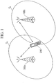
- FIG. 1 is a conceptual configuration diagram of a wireless communication system (also referred to as a communication system) according to a first embodiment of the present invention.
- the wireless communication system uses an orthogonal frequency division multiplexing (OFDM) technique.
- FIG. 1 shows the case where a base station 100a and a base station 100b communicate with a terminal 200 which is a mobile phone.
- OFDM orthogonal frequency division multiplexing
- the base station 100a and the base station 100b perform provide a unicast communication service for performing different communication for each terminal, such as voice communication, TV telephone communication, or packet communication, at a frequency f1. Also, the base station 100a and the base station 100b provide an MBMS communication service that can be commonly used by all terminals, such as voice communication and video communication, at a frequency f2.
- a unicast service is provided as an independent service for each base station.
- a service of the same content is provided in a fixed area (MBSFN area).
- the base station 100a and the base station 100b provide the same MBMS service.
- An area C A indicates a range in which the base station 100a is communicable with the terminal 200.
- An area C B indicates a range in which the base station 100b can communicate with the terminal 200.
- the terminal 200 is generally connected to one base station of the base station 100a and the base station 100b, so that desired communication is performed. If the MBMS service is received, the terminal 200 simultaneously receives signals of the base station 100a and the base station 100b and receives the MBMS service by demodulating a combined signal thereof.
- a terminal capable of simultaneously receiving a unicast service and an MBMS service in an environment where these services are provided will be described.
- FIG. 2 is a schematic block diagram showing the configuration of the base station 100a according to the first embodiment of the present invention. Since the configuration of the base station 100b in FIG. 1 is the same as that of the base station 100a, descriptions thereof will be omitted.
- the base station 100a includes antenna units 10-1, 10-2, and 10-3, a transmission unit 11, a reception unit 12, a control unit 13, and duplexers 14-1 and 14-2.
- the antenna units 10-1, 10-2, and 10-3 transmit/receive an OFDM signal of a radio frequency band to/from the terminal 200.
- the antenna unit 10-1 transmits an MBMS signal output from the transmission unit 11 to the terminal 200.
- the antenna unit 10-2 transmits a unicast signal output from the duplexer 14-1 to the terminal 200.
- the antenna unit 10-2 outputs a unicast signal received from the terminal 200 to the duplexer 14-1.
- the antenna unit 10-3 transmits a unicast signal output from the duplexer 14-2 to the terminal 200.
- the antenna unit 10-3 outputs a unicast signal received from the terminal 200 to the duplexer 14-2.
- the transmission unit 11 performs a transmission process (a modulation process, an up-conversion process, and the like) for a transmission signal to be transmitted from the base station 100a to the terminal 200 among signals output from the control unit 13, and outputs the signal to the antenna 10-1 and the duplexers 14-1 and 14-2.
- a transmission process a modulation process, an up-conversion process, and the like
- the reception unit 12 performs a reception process (a demodulation process, a down-conversion process, and the like) for a reception signal transmitted from the terminal 200 to the base station 100a among signals output from the duplexers 14-1 and 14-2, and outputs the signal to the control unit 13.
- a reception process a demodulation process, a down-conversion process, and the like
- the control unit 13 outputs a signal to be transmitted from the base station 100a to the terminal 200 to the transmission unit 11. Also, the control unit 13 receives a signal transmitted from the terminal 200 to the base station 100a from the reception unit 12. The control unit 13 controls each part of the base station 100a.
- the duplexers 14-1 and 14-2 are devices for sharing transmission/reception signals using one antenna.
- the duplexer 14-1 outputs a transmission signal output from the transmission unit 11 to the antenna unit 10-2. Also, the duplexer 14-1 outputs a reception signal output from the antenna unit 10-2 to the reception unit 12.
- the duplexer 14-2 outputs a transmission signal output from the transmission unit 11 to the antenna unit 10-3. Also, the duplexer 14-2 outputs a reception signal output from the antenna unit 10-3 to the reception unit 12.
- FIG. 3 is a schematic block diagram showing the configuration of the terminal 200 according to the first embodiment of the present invention.
- the terminal 200 includes antenna units 20-1 and 20-2, a transmission unit 21, a reception unit 22a, a control unit 23, and a duplexer 24.
- the antenna units 20-1 and 20-2 transmit/receive an OFDM signal of a radio frequency band to/from the base stations 200a and 200b.
- the antenna unit 20-1 transmits/receives unicast signals to/from the base stations 200a and 200b.
- the antenna unit 20-2 receives MBMS signals or unicast signals from the base stations 100a and 100b.
- the transmission unit 21 performs a transmission process (a modulation process, an up-conversion process, and the like) for a transmission signal to be transmitted from the terminal 200 to the base stations 100a and 100b among signals output from the control unit 23, and outputs the signal to the duplexer 24.
- a transmission process a modulation process, an up-conversion process, and the like
- the reception unit 22a performs a reception process (a demodulation process, a down-conversion process, and the like) for reception signals transmitted from the base stations 100a and 100b to the terminal 200 among signals output from the duplexer 24 or the antenna unit 20-2, and outputs the signals to the control unit 23.
- a reception process a demodulation process, a down-conversion process, and the like
- the control unit 23 outputs a signal to be transmitted from the terminal 200 to the base stations 100a and 100b to the transmission unit 21. Also, the control unit 23 receives signals transmitted from the base stations 100a and 100b to the terminal 200 from the reception unit 22a. Also, the control unit 23 controls each part of the terminal 200.
- the duplexer 24 is a device for sharing transmission/reception signals by one antenna unit.
- the duplexer 24 outputs a transmission signal output from the transmission unit 21 to the antenna unit 20-1. Also, the duplexer 24 outputs a reception signal output from the antenna unit 20-1 to the reception unit 22a.
- unicast data communication is performed by 2x2 multiple input multiple output (MIMO) communication.
- MIMO multiple input multiple output
- the terminal 200 in FIG. 3 transmits a transmission signal using only one antenna, but one duplexer is added so that the antenna unit 20-2 can perform transmission if transmission, like transmit diversity, is performed using two antennas.
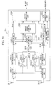
- FIG. 4 is a schematic block diagram showing the configuration of the transmission unit 11 ( FIG. 2 ) of the base station 100 according to the first embodiment of the present invention.
- the transmission unit 11 includes a mapping unit 1101, modulation units 1102-1 to 1102-3, symbol arrangement units 1103-1 to 1103-3, IFFT (inverse fast Fourier transform) processing units 1104-1 to 1104-3, and radio units 1105-1 to 1105-3.
- mapping unit 1101 modulation units 1102-1 to 1102-3
- symbol arrangement units 1103-1 to 1103-3 symbol arrangement units 1103-1 to 1103-3
- IFFT inverse fast Fourier transform
- An MBMS transmission signal (MBMS data) and a unicast transmission signal (unicast data) are separately generated.
- the MBMS data is transmitted from the antenna unit 10-1.
- the unicast data is transmitted from the antenna units 10-2 and 10-3.
- the MBMS data and the unicast data use different frequency bands. For example, the MBMS data is transmitted to the terminal 200 using a band of a center frequency f1, and the unicast data is transmitted to the terminal 200 using a band of a center frequency f2.
- the unicast communication corresponds to 2x2 MIMO communication and communication with the terminal 200 is performed using the antenna units 10-2 and 10-3.
- Data such as MBMS data corresponding to MBMS information common for all users or control data corresponding to a control signal is input from the control unit 13 ( FIG. 2 ) to the modulation unit 1102-1.
- the modulation unit 1102-1 performs modulation corresponding to each data and obtains a modulated data symbol.
- MBMS data is modulated by 64 quadrature amplitude modulation (64QAM) and control data is modulated by quadrature phase shift keying (QPSK) or the like, so that data symbols can be obtained.
- 64QAM quadrature amplitude modulation
- QPSK quadrature phase shift keying
- the data symbols modulated by the modulation unit 1102-1 are input to the symbol arrangement unit 1103-1.
- a reference signal (RS) is also input to the symbol arrangement unit 1103-1.
- the symbol arrangement unit 1103-1 arranges the data symbols generated by the modulation unit 1102-1 and the RS in resource elements so that a predetermined symbol arrangement is made.
- the IFFT processing unit 1104-1 converts each arranged symbol from a frequency domain signal into a time domain signal.
- the radio unit 1105-1 performs conversion into a signal of a radio frequency band.
- the signal is transmitted from the antenna unit 10-1 ( FIG. 2 ) to the terminal 200.
- Data such as unicast data corresponding to information for allowing the base station 100a to individually communicate with each user or control data corresponding to a control signal for the unicast communication is input from the control unit 13 ( FIG. 2 ) to the mapping unit 1101.
- the data input to the mapping unit 1101 is separated into data to be transmitted to the antenna units 10-2 and 10-3 for performing MIMO communication, and is input to the modulation units 1102-2 and 1102-3 corresponding to the antenna units 10-2 and 10-3. That is, data to be transmitted from the antenna unit 10-2 is input from the mapping unit 1101 to the modulation unit 1102-2. Data to be transmitted from the antenna unit 10-3 is input from the mapping unit 1101 to the modulation unit 1102-3.
- the modulation unit 1102-2 modulates the unicast data or the control data output from the mapping unit 1101 and obtains a modulated data symbol. For example, in the case in which a communication environment of a user who performs communication is good, user data is modulated by 64QAM and control data is modulated by QPSK or the like, so that data symbols can be obtained.
- the data symbols modulated by the modulation unit 1102-2 are input to the symbol arrangement unit 1103-2.
- An RS is also input to the symbol arrangement unit 1103-2.
- the symbol arrangement unit 1103-2 arranges the data symbols generated by the modulation unit 1102-2 and the RS in resource elements so that a predetermined symbol arrangement is made.
- the IFFT processing unit 1104-2 converts each symbol arranged by the symbol arrangement unit 1103-2 from a frequency domain signal into a time domain signal.
- the radio unit 1105-2 performs conversion into a signal of a radio frequency band.
- the signal is transmitted from the antenna unit 10-2 ( FIG. 2 ) to the terminal 200.
- the modulation unit 1102-3 modulates the unicast data or the control data output from the mapping unit 1101 and obtains a modulated data symbol. For example, in the case in which a communication environment of a user who performs communication is good, user data is modulated by 64QAM and control data is modulated by QPSK or the like, so that data symbols can be obtained.
- the data symbols modulated by the modulation unit 1102-3 are input to the symbol arrangement unit 1103-3.
- An RS is also input to the symbol arrangement unit 1103-3.
- the symbol arrangement unit 1103-3 arranges the data symbols generated by the modulation unit 1102-3 and the RS in resource elements so that a predetermined symbol arrangement is made.
- the IFFT processing unit 1104-3 converts each symbol arranged by the symbol arrangement unit 1103-3 from a frequency domain signal into a time domain signal.
- the radio unit 1105-3 performs conversion into a signal of a radio frequency band.
- the signal is transmitted from the antenna unit 10-3 ( FIG. 2 ) to the terminal 200.
- the base station checks the capacity of each user by terminal capacities received from the terminals.
- 2x2 MIMO data is arranged for the terminal corresponding to the 2x2 MIMO.
- Data for a single antenna is arranged for a terminal of the single antenna.
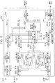
- FIG. 5 is a schematic block diagram showing the configuration of the reception unit 22a ( FIG. 3 ) of the terminal 200 according to the first embodiment of the present invention.
- the reception unit 22a includes RF (radio frequency) reception units 2201-1 and 2201-2, FFT (fast Fourier transform) processing units 2202-1 and 2202-2, separation units 2203-1 and 2203-2, an offset estimation unit 2204, a unicast channel estimation unit 2205, a unicast demodulation unit 2206, synthesizer units 2207-1 and 2207-2, a temperature-compensated crystal oscillator 2210, an MBMS channel estimation unit 2211, and an MBMS demodulation unit 2212.
- RF radio frequency
- FFT fast Fourier transform
- the RF reception unit 2201-1 demodulates a radio signal received by the antenna unit 20-1 ( FIG. 3 ) and outputs the demodulated signal to the FFT processing unit 2202-1.
- the FFT processing unit 2202-1 converts a time domain signal demodulated by the RF reception unit 2201-1 into a frequency domain signal, and outputs the frequency domain signal to the separation unit 2203-1.
- the separation unit 2203-1 separates the signal, converted by the FFT processing unit 2202-1 from the time domain signal into the frequency domain signal, into an RS and data.
- the separation unit 2203-1 outputs the RS to the offset estimation unit 2204 and the unicast channel estimation unit 2205, and outputs the data to the unicast demodulation unit 2206.
- the RF reception unit 2201-2 demodulates a radio signal received by the antenna unit 20-2 ( FIG. 3 ) and outputs the demodulated signal to the FFT processing unit 2202-2.
- the FFT processing unit 2202-2 converts a time domain signal demodulated by the RF reception unit 2201-2 into a frequency domain signal, and outputs the frequency domain signal to the separation unit 2203-2.
- the separation unit 2203-2 separates the signal, converted by the FFT processing unit 2202-2 from the time domain signal into the frequency domain signal, into an RS and data.
- the separation unit 2203-2 outputs the RS to the offset estimation unit 2204 and the unicast channel estimation unit 2205, and outputs the unicast data to the unicast demodulation unit 2206.
- the separation unit 2203-2 outputs the RS to the offset estimation unit 2204 and the MBMS channel estimation unit 2211, and outputs the MBMS data to the MBMS demodulation unit 2212.
- the offset estimation unit 2204 estimates a frequency offset error between the base station and the terminal based on the RSs separated by the separation unit 2203-1 and 2203-2.
- the offset estimation unit 2204 outputs a voltage control signal calculated based on the estimation result to the temperature-compensated crystal oscillator 2210.
- the temperature-compensated crystal oscillator 2210 generates a reference signal f0 to receive a signal from the base station based on the output from the offset estimation unit 2204.
- the synthesizer unit 2207-1 generates a local frequency signal fcu for performing demodulation by the RF reception unit 2201-1 based on the reference signal f0 output from the temperature-compensated crystal oscillator 2210, and outputs the local frequency signal fcu to the RF reception unit 2201-1.
- the synthesizer unit 2207-2 generates a local frequency signal fcu/fcm for performing demodulation by the RF reception unit 2201-2 based on the reference signal f0 output from the temperature-compensated crystal oscillator 2210, and outputs the local frequency signal fcu/fcm to the RF reception unit 2201-2.
- the unicast channel estimation unit 2205 performs channel estimation on a unicast signal based on the RSs separated by the separation units 2203-1 and 2203-2, and outputs the channel estimation result to the unicast demodulation unit 2206.
- the unicast demodulation unit 2206 demodulates unicast data using the unicast data output from the separation units 2203-1 and 2203-2 and an estimation value output from the unicast channel estimation unit 2205.
- the MBMS channel estimation unit 2211 performs channel estimation on an MBMS signal based on the MBMS RS output from the separation unit 2203-2, and outputs the channel estimation result to the MBMS demodulation unit 2212.
- the MBMS demodulation unit 2212 demodulates MBMS data based on the MBMS data output from the separation unit 2203-2 and an estimation value generated by the MBMS channel estimation unit 2211.
- the synthesizer unit 2207-1 includes a PLL (phase locked loop) 2208-1 and a VCO (voltage controlled oscillator) 2209-1.
- the PLL 2208-1 feeds back information of a phase difference between the reference frequency f0 output from the temperature-compensated crystal oscillator 2210 and the local frequency fcu output from the VCO 2209-1 to the VCO 2209-1. Thereby, the local frequency of the VCO 2209-1 is synchronized with the reference frequency.
- the synthesizer unit 2207-2 has the same configuration as the synthesizer unit 2207-1 and performs the same operation as the synthesizer unit 2207-1.
- the synthesizer unit 2207-2 can perform switching to an MBMS local frequency fcm by switching a frequency setting of a PLL 2208-2.
- the case where the MBMS is received by the reception unit 22a is different from the case where only the unicast communication is performed by the reception unit 22a.
- An arrow indicated by a dotted line in FIG. 5 indicates a signal which flows when a unicast signal is received.
- An arrow indicated by a dashed line in FIG. 5 indicates a signal which flows when an MBMS signal is received.
- FIG. 6 is a schematic diagram showing the case where the terminal 200 receives unicast signals transmitted from the base station 100a according to the first embodiment of the present invention.
- An MBMS signal is transmitted from the antenna unit 10-1 of the base station 100a to the terminal 200.
- the unicast signals are transmitted from the antenna units 10-2 and 10-3 of the base station 100a to the terminal 200.
- Common data is transmitted as an MBMS signal from the base station 100a to all terminals located in the area C A ( FIG. 1 ) where the base station 100a can communicate with terminals.
- the terminal 200 which performs only unicast signal communication does not receive the MBMS signal.
- the unicast signals are transmitted from the base station 100a to the terminal 200 as signals corresponding to 2x2 MIMO.
- the terminal 200 has the two antenna units 20-1 and 20-2, which both receive the unicast signals. Both the received signals are input to the unicast demodulation unit 2206 ( FIG. 5 ) which demodulates the unicast signals.
- the unicast demodulation unit 2206 performs demodulation corresponding to the 2x2 MIMO using the received signals input from the antenna units 20-1 and 20-2.
- FIG. 7 is a schematic diagram showing the case where the terminal 200 receives unicast signals and an MBMS signal transmitted from the base station 100a according to the first embodiment of the present invention.
- the base station 100a transmits the MBMS signal from the antenna unit 10-1, and transmits unicast signals from the antenna units 10-2 and 10-3.
- the unicast signals are received only by the antenna unit 20-1 of the terminal 200.
- the base station 100a transmits signals for one antenna.
- the terminal 200 uses the two antenna units 20-1 and 20-2 for MBMS signal reception and unicast signal reception.
- the antenna unit 20-1 receives the unicast signals from the base station 100a.
- the unicast signals received by the antenna unit 20-1 are demodulated by the unicast demodulation unit 2206 ( FIG. 5 ).
- the unicast demodulation unit 2206 demodulates the unicast signals received by the antenna unit 20-1.
- the antenna unit 20-2 receives the MBMS signal from the base station 100a.
- the MBMS signal received by the antenna unit 20-2 is demodulated by the MBMS demodulation unit 2212 ( FIG. 5 ).
- the signal demodulated by the unicast demodulation unit 2206 or the MBMS demodulation unit 2212 is processed according to service content, and image data, audio data, or packet data is extracted.
- both of the antenna units 20-1 and 20-2 receive unicast signals and operate as the MIMO of the two receiving antennas.
- the temperature-compensated crystal oscillator 2210 outputs a signal of the reference frequency f0.
- the control unit 23 sets both of the synthesizer units 2207-1 and 2207-2 to the local frequency fcu to receive the unicast signals.
- the RF reception units 2201-1 and 2201-2 convert unicast RF signals into baseband signals by the local frequency fcu. If OFDM communication is performed, a cyclic prefix (CP) is generally inserted to remove the effect of a delay wave. Thus, the RF reception units 2201-1 and 2201-2 remove CPs and output the results to the FFT processing units 2202-1 and 2202-2.
- CP cyclic prefix
- the FFT processing units 2202-1 and 2202-2 convert time domain baseband signals into frequency domain signals by an FFT. Unicast communication data converted into the frequency domain is output to the separation units 2203-1 and 2203-2.
- the separation unit 2203-1 separates the received data into an RS and a data component.
- Positions into which RSs are inserted into signals to be transmitted from the antenna units 10-2 and 10-3 of the base station 100a are determined in advance between the base station 100a and the terminal 200.
- FIG. 8 is a diagram showing an example of unicast signals to be transmitted from the base station 100a to the terminal 200 according to the first embodiment of the present invention.
- the horizontal axis is a time axis
- the vertical axis is a frequency axis.
- one box represents one resource element.
- 12 subcarriers are arranged in a frequency-axis direction
- one subframe (1 ms) including 14 symbols is arranged in a time-axis direction.
- a subcarrier interval is 15 kHz.
- a guard interval called a CP is provided in each symbol.
- the CP is determined based on an amount of delay which is determined in a wireless communication system.
- RS1 is an RS which is transmitted from the antenna unit 10-2 of the base station 100a.
- RS2 is an RS which is transmitted from the antenna unit 10-3.
- the terminal 200 respectively separates signals transmitted from the base station 100a by the separation unit 2003-1.
- the separation unit 2003-1 outputs the RSs RS1 and RS2 to the offset estimation unit 2204 and the unicast channel estimation unit 2205.
- the separation unit 2003-1 outputs data other than the RSs as unicast communication data to the unicast demodulation unit 2206.
- the separation unit 2203-2 also separates RSs.
- the separation unit 2203-2 outputs RS1' corresponding to RS1 and RS2' corresponding to RS2 to the offset estimation unit 2204 and the unicast channel estimation unit 2205.
- the separation unit 2203-2 outputs the other unicast communication data to the unicast demodulation unit 2206.
- the RS is inserted into a predetermined position in a symbol in FIG. 8 .
- the RS may be frequency-shifted and inserted for each base station, or may be temporally hopped and inserted.
- the separation units 2203-1 and 2203-2 can specify RS positions by base station identification information.
- the separation units 2203-1 and 2203-2 extract the specified RSs and output the extracted specified RSs to the offset estimation unit 2204 and the unicast channel estimation unit 2205.
- the separation units 2203-1 and 2203-2 output symbols of the other data parts to the unicast demodulation unit 2206.
- the offset estimation unit 2204 detects phase changes by lapses of time of the RSs RSI, RS2, RS1', and RS2' input from the separation units 2203-1 and 2203-2, and estimates a frequency error.
- the offset estimation unit 2204 synchronizes a frequency of the base station with that of the terminal 200 by correcting a frequency of the temperature-compensated crystal oscillator 2210 based on the estimated frequency error.
- the unicast channel estimation unit 2205 performs channel estimation by the known minimum mean square error-channel (MMSE-CH) estimation method based on the input RS1, RS2, RS1', and RS2'.
- MMSE-CH known minimum mean square error-channel
- Channel estimation values estimated by the unicast channel estimation unit 2205 are input to the unicast demodulation unit 2206.
- the unicast demodulation unit 2206 corrects and demodulates data Data 1 and Data 2 input from the separation units 2203-1 and 2203-2 by the estimation values input from the unicast channel estimation unit 2205.
- the data demodulated by the unicast demodulation unit 2206 as described above is processed as unicast data.
- the terminal 200 operates as a 2x2 MIMO receiver by performing the process as described above.
- the terminal 200 receives an MBMS signal transmitted by the base station 100a. If the terminal 200 receives the MBMS signal, it is possible to receive only the MBMS signal. For example, if there is an incoming signal of voice communication even when the terminal 200 receives an MBMS video, one of the two antenna units 20-1 and 20-2 is allocated for use in unicast signal reception, and the other is allocated for use in MBMS signal reception, so that a phone call can be received.
- the RF reception unit 2201-1, the FFT processing unit 2202-1, the separation unit 2203-1, and the synthesizer unit 2207-1 are used for the unicast signal reception. Also, the RF reception unit 2201-2, the FFT processing unit 2202-2, the separation unit 2203-2, and the synthesizer unit 2207-2 are used for the MBMS signal reception.
- the antenna unit 20-1 is used to receive unicast signals.
- the temperature-compensated crystal oscillator 2210 is set to the reference frequency f0.
- the synthesizer unit 2207-1 generates the local frequency signal fcu to receive the unicast signals based on the reference signal f0.
- the unicast signal received by the antenna unit 20-1 is converted into a baseband signal by the RF reception unit 2201-1 based on the local frequency fcu.
- the RF reception unit 2201-1 removes CPs from the baseband signal, and outputs the results to the FFT processing unit 2202-1.
- the FFT processing unit 2202-1 performs signal processing by an FFT and converts time domain signals into frequency domain signals.
- the frequency domain signals are input to the separation unit 2203-1.
- the separation unit 2203-1 separates the received signals into RSs and data based on a data arrangement, which is predetermined with the base station 100a.
- the RSs are input to the offset estimation unit 2204 and the unicast channel estimation unit 2205.
- the data is input to the unicast demodulation unit 2206.
- the offset estimation unit 2204 estimates a frequency error based on time changes of phases of the input RSs.
- the offset estimation unit 2204 corrects a frequency of the temperature-compensated crystal oscillator 2210 in response to the frequency error, and adjusts the output frequency of the temperature-compensated crystal oscillator 2210.
- a reference frequency signal of the temperature-compensated crystal oscillator 2210 is synchronized with the frequency of the base station, which receives the unicast signals.
- the unicast channel estimation unit 2205 performs estimation on the input RSs using the MMSE-CH estimation method.
- the estimation results are input to the unicast demodulation unit 2206.
- the unicast demodulation unit 2206 corrects data input from the separation unit 2203-1 by estimation values input from the unicast channel estimation unit 2205, and demodulates unicast data.
- the demodulated unicast data is processed in response to a type of data such as a control signal of a wireless protocol, audio data, or image data.
- the antenna unit 20-2 of the terminal 200 receives an MBMS signal.
- the synthesizer unit 2207-2 generates the local frequency fcm for demodulating the MBMS signal transmitted at the center frequency f2 based on the reference frequency f0 generated by the temperature-compensated crystal oscillator 2210.
- This local frequency fcm is input to the RF reception unit 2201-2.
- the RF reception unit 2201-2 converts an RF signal of the MBMS received by the antenna unit 20-2 into a baseband signal based on the local frequency fcm.
- the MBMS signal is also an OFDM signal into which a CP is inserted.
- the RF reception unit 2201-2 removes the CP and outputs the baseband signal to the FFT processing unit 2202-2.
- the terminal 200 can receive the MBMS signal by combining signals simultaneously transmitted from a plurality of base stations.
- FIG. 9 is a diagram showing an example of an MBMS signal transmitted from the base station 100a to the terminal 200 according to the first embodiment of the present invention.
- the horizontal axis is a time axis
- the vertical axis is a frequency axis.
- one box represents one resource element.
- 12 subcarriers are arranged in a frequency-axis direction
- one subframe (1 ms) including 6 symbols is arranged in a time-axis direction.
- the MBMS can be received by combining signals from a plurality of base stations, and has a possibility that a further delayed signal may be received compared to unicast communication.
- a CP of the MBMS is set to be longer than that of the unicast communication.
- a subcarrier interval is 7.5 kHz.
- a signal is transmitted from one antenna of the base station without performing communication by MIMO.
- the RS serves as only an RS of an MBMS antenna.
- the MBMS signal is appropriately arranged in conjunction with the number of symbols.
- the MBMS signal transmitted from the base station is input to the FFT processing unit 2202-2.
- the FFT processing unit 2202-2 converts the input baseband signal from a time domain signal into a frequency domain signal by signal processing of an FFT.
- the MBMS signal converted into the frequency domain signal is input to the separation unit 2203-2.
- an RS arrangement is predetermined between the base station and the terminal.
- the separation unit 2203-2 separates an RS and data based on the predetermined arrangement, outputs the RS to the MBMS channel estimation unit 2211, and outputs a data signal to the MBMS demodulation unit 2212.
- the MBMS channel estimation unit 2211 performs channel estimation based on the input RS and the MMSE-CH estimation method or the like. As in the unicast communication, other estimation methods may be used.
- a channel estimation value of the MBMS signal estimated as described above is output to the MBMS demodulation unit 2212.
- the MBMS demodulation unit 2212 corrects and demodulates the MBMS data input from the separation unit 2203-2 by the channel estimation value from the MBMS channel estimation unit 2211.
- the MBMS data includes image data, audio data, and the like.
- the data is displayed on a screen provided on a mobile phone by an application corresponding to a service, or is played as music data by a speaker, an earphone, or the like.
- the terminal 200 when MBMS signal reception and unicast signal communication are simultaneously performed.
- the unicast communication is usually in a standby state.
- the terminal 200 receives paging of notification once every several seconds to several tens of seconds.
- the terminal 200 checks whether or not there is an incoming signal directed to its own terminal or whether or not it is necessary to output location information.
- the unicast communication continues a state in which paging is received once every several second to several tens of seconds.
- offset estimation is not performed based on data of a receiver of the unicast signals
- offset estimation is performed at a receiver of an MBMS signal. If no paging is received at the receiver of the unicast signal, the RF reception unit 2201-1, the FFT processing unit 2202-1, the separation unit 2203-1, and the synthesizer unit 2207-1 wait in the standby state, and minimize power consumption.
- the antenna unit 20-2 receives the MBMS signal.
- the synthesizer unit 2207-2 is set to the local frequency fcm.
- the MBMS signal received by the antenna unit 20-2 is converted into a baseband signal by the RF reception unit 2201-2, and is converted into a frequency domain signal by the FFT processing unit 2202-2.
- the frequency domain signal is output to the separation unit 2203-2.
- the separation unit 2203-2 outputs an RS of the separated MBMS signal to the offset estimation unit 2204 and the MBMS channel estimation unit 2211. Also, the separation unit 2203-2 outputs the data signal to the MBMS demodulation unit 2212.
- the offset estimation unit 2204 performs offset estimation based on the RS of the MBMS signal, and performs correction of the temperature-compensated crystal oscillator 2210.
- the MBMS demodulation unit 2212 performs demodulation based on estimation data of the MBMS channel estimation unit 2211 and MBMS data from the separation unit 2203-2, and outputs the MBMS data.
- the terminal 200 can receive the MBMS signal even when the receiver of the unicast signals is in the standby state. If the receiver of the unicast signals performs a paging reception operation, the same process as that of the above-described unicast signal communication state is performed so that the receiver of the unicast signals is in the communication state.
- the terminal 200 can transmit/receive high-speed data to/from the base station as a MIMO receiver. Also, if the MBMS signal is received, the terminal 200 can perform unicast signal communication with the base station.
- the terminal 200 can receive an incoming signal even when the unicast signals are received.
- the unicast signals are received simultaneously upon receipt of the MBMS signal.
- the unicast signal reception is unnecessary, it is possible to reduce power consumption by preventing power supply to a reception system for receiving the unicast signals.
- the terminal 200 operates like a general MIMO receiver. Accordingly, even when the base station provides a service in which an MBMS signal and unicast signals are transmitted to the terminal by time division in one frequency band, the terminal 200 can simultaneously receive the MBMS signal and the unicast signals.
- the terminal 200 performs offset correction by an RS of the MBMS signal.
- the temperature-compensated crystal oscillator 2210 can operate in a state in which it is substantially synchronized with the base station, so that the reception quality of the paging can be improved.
- the transmission units 11 (referred to as signal transmission units) of the base stations 100a and 100b (also referred to as radio transmission devices or transmission devices) transmit unicast signals or MBMS signals as a type of multicast signal to the terminal 200 (also referred to as a radio reception device).
- the plurality of RF reception units 2201-1 and 2202-2 (also referred to as signal reception units) of the terminal 200 receive the unicast signals or the MBMS signals from the base stations 100a and 100b.
- control unit 23 also referred to as a first control unit of the terminal 200 receives only unicast signals from the base stations 100a and 100b
- the unicast signals are received from the base stations 100a and 100b using all of the plurality of RF reception units 2201-1 and 2201-2.
- control unit 23 (also referred to as a second control unit) of the terminal 200 receives unicast signals and MBMS signals
- the control unit 23 receives the unicast signals from the base stations 100a and 100b using the RF reception units 2201-1 of the plurality of RF reception units 2201-1 and 2201-2, and also receives the MBMS signals from the base stations 100a and 100b using the other RF reception unit 2201-2 of the plurality of RF reception units 2201-1 and 2201-2.
- the terminal 200 includes the plurality of RF reception units (the RF reception units 2201-1 and 2201-2), the plurality of FFT processing units (the FFT processing units 2202-1 and 2202-2), the plurality of channel estimation units (the unicast channel estimation units 2205 and the MBMS channel estimation unit 2211), and the plurality of demodulation units (the unicast demodulation unit 2206 and the MBMS demodulation unit 2212).
- control unit 23 of the terminal 200 operates all of the plurality of RF reception units, the plurality of FFT processing units, and the plurality of channel estimation units as MIMO transceivers.
- the control unit 23 of the terminal 200 operates some of the plurality of RF transmission/reception units, the plurality of FFT processing units, the plurality of channel estimation units, and the plurality of demodulation units for use in the MBMS communication, and operates the other RF reception unit, the other FFT processing unit, the other channel estimation unit, and the other demodulation unit for use in the unicast communication, so that unicast signal transmission/reception and MBMS signal reception are simultaneously performed.
- MBMS communication and unicast communication can be simultaneously performed even when a dedicated terminal for the MBMS communication is not provided.
- LTE long term evolution
- 3G 3rd generation
- GSM global system for mobile communications
- offset estimation unit 2204 of the terminal 200 receives unicast signals and MBMS signals from the base stations 100a and 100b in this embodiment, offset estimation is performed using RSs included in the unicast signals.
- offset estimation is performed using RSs included in the MBMS signals.
- MBMS communication quality of both the unicast/MBMS can be highly maintained by performing offset estimation by the unicast signals upon unicast communication. If the unicast communication is in a stopped state, MBMS communication quality can be maintained by performing offset estimation by MBMS RSs. If incoming signals of unicast signals are received during MBMS signal reception, paging is received from a state in which it is substantially synchronized with a network in the MBMS, and thus the reception quality of paging is improved.
- the terminal 200 for 2x2 MIMO has been described in this embodiment, but this embodiment may be applicable to a terminal corresponding to MIMO reception in which the number of receiving antennas for 4x4 MIMO is greater than or equal to 2.
- the configuration of a terminal corresponding to MIMO reception in which the number of receiving antennas is greater than or equal to 2 will be described later.
- the terminal 200 of the second embodiment has a reception unit 22b in place of the reception unit 22a provided in the terminal 200 according to the first embodiment.
- FIG. 10 is a schematic block diagram showing the configuration of the reception unit 22b of the terminal 200 according to the second embodiment of the present invention.
- the same reference symbols are assigned to parts of the reception unit 22b having the same configurations as those of the reception unit 22a ( FIG. 5 ), and descriptions thereof will be omitted.
- Processes of the synthesizer units 2207-1 and 2207-2 of the reception unit 22b according to the second embodiment are different from those of the synthesizer units 2207-1 and 2207-2 of the reception unit 22a according to the first embodiment.
- An arrow indicated by a dashed line in FIG. 10 indicates a signal which flows when a unicast signal is received.
- An arrow indicated by a dotted line in FIG. 10 indicates a signal which flows when an MBMS signal is received.
- the synthesizer unit 2207-1 is used for unicast signal communication and the synthesizer unit 2207-2 is used for MBMS signal reception. If only unicast communication is performed, the local signal fcu generated by the synthesizer unit 2207-1 is output to the RF reception unit 2201-1 and the RF reception unit 2201-2.
- the RF reception unit 2201-1 and the RF reception unit 2201-2 convert received RF signals into baseband signals based on the local signal generated by the synthesizer unit 2207-1.
- the local frequency fcm from the synthesizer unit 2207-2 is input to the RF reception unit 2201-2.
- a switch circuit for selectively using the local signal fcu from the synthesizer unit 2207-1 and the local signal fcm from the synthesizer unit 2207-2 is integrated into the RF reception unit 2201-2.
- the control unit 23 FIG. 3 ) switches the RF reception unit 2201-2 to receive the local signal of the synthesizer unit 2207-2.
- the RF reception unit 2201-2 converts the received MBMS signal into a baseband signal using the local signal from the synthesizer unit 2207-2.
- the other operations are the same as those of the first embodiment.
- the terminal 200 of the third embodiment has a reception unit 22c in place of the reception unit 22a provided in the terminal 200 according to the first embodiment.
- FIG. 11 is a schematic block diagram showing the configuration of the reception unit 22c of the terminal 200 according to the third embodiment of the present invention.
- the same reference symbols are assigned to parts of the reception unit 22c having the same configurations as those of the reception unit 22a ( FIG. 5 ), and descriptions thereof will be omitted.
- An arrow indicated by a dotted line in FIG. 11 indicates a signal which flows when a unicast signal is received.
- An arrow indicated by a dashed line in FIG. 11 indicates a signal which flows when an MBMS signal is received.
- the reception unit 22c of the third embodiment can also output an MBMS RS or an MBMS data signal from the separation unit 2203-1 to the MBMS channel estimation unit 2211, the MBMS demodulation unit 2212, and the offset estimation unit 2204, and can also receive an MBMS signal from the antenna unit 20-1.
- the operation when the antenna unit 20-1 receives unicast signals and the antenna unit 20-1 receives an MBMS signal is the same as that of the first embodiment described with reference to FIG. 5 .
- the RF reception unit 2201-1, the FFT processing unit 2202-1, and the separation unit 2203-1 are in a standby state with paging listening
- the RF reception unit 2201-1, the FFT processing unit 2202-1, and the separation unit 2203-1 are started to check a reception state of the MBMS signal.
- the MBMS signal is received, the MBMS signal is processed and demodulated through the RF reception unit 2201-2, the FFT processing unit 2202-2, and the separation unit 2203-2.
- the local frequency is set to fcm by the synthesizer unit 2207-1, and the MBMS signal received by the antenna unit 20-1 is received.
- the RF reception unit 2201-1 converts the received MBMS signal into a baseband signal and the reception level thereof is checked. Likewise, the RF reception unit 2201-2 also measures a reception level. If the reception level of the antenna unit 20-1 is higher, an MBMS signal reception system is changed to the side of the antenna unit 20-1.
- an MBMS signal is received at the side of the antenna unit 20-1, and unicast signals are received at the side of the antenna unit 20-2.
- the RF reception unit 2201-2 down-converts the MBMS signal received by the antenna unit 20-1 by setting the local frequency of the synthesizer unit 2207-1 to fcm.
- the MBMS signal converted into a baseband signal is converted by the FTT processing unit 2201-1 from a time domain signal into a frequency domain signal.
- the separation unit 2203-1 separates an RS RS-M and a data part based on a symbol pattern of the MBMS signal.
- the RS is output to the MBMS channel estimation unit 2211 and the offset estimation unit 2204.
- the offset estimation unit 2204 performs offset estimation based on the RS RS-M received by the antenna unit 20-1, and performs correction of the temperature-compensated crystal oscillator 2210.
- Estimation data estimated by the MBMS channel estimation unit 2211 is output to the MBMS demodulation unit 2212, and MBMS data is demodulated in conjunction with MBMS data output from the separation unit 2203-1.
- the RF reception unit 2201-2 While the RF reception unit 2201-2, the FFT processing unit 2202-2, and the separation unit 2203-2 are in a paging listening state, the RF reception unit 2201-2 equally measures a reception level of an MBMS signal. If the reception quality of the antenna unit 20-2 is higher than that of the antenna unit 20-1, the MBMS signal reception system can be changed to the antenna unit 20-2.
- the offset estimation unit 2204 performs offset estimation using unicast RSs output from the separation unit 2203-2, and performs correction of the temperature-compensated crystal oscillator 2210.
- the terminal 20Q of the third embodiment can receive an MBMS signal by constantly selecting an antenna having good reception characteristics. Thus, it is possible to improve throughput characteristics of the terminal 200.
- the terminal 200 ( FIG. 3 ) according to the first embodiment has the two antenna units 20-1 and 20-2, but the terminal 200 according to the fourth embodiment has N antenna units 20-1 to 20-N (N is an integer greater than or equal to 3).
- the terminal 200 of the fourth embodiment has a reception unit 22d in place of the reception unit 22a provided in the terminal 200 according to the first embodiment.
- FIG. 12 is a schematic block diagram showing the configuration of the reception unit 22d of the terminal 200 according to the fourth embodiment of the present invention.
- the same reference symbols are assigned to parts of the reception unit 22d having the same configurations as those of the reception unit 22a ( FIG. 5 ), and descriptions thereof will be omitted.
- An arrow indicated by a dotted line in FIG. 12 indicates a signal which flows when a unicast signal is received.
- An arrow indicated by a dashed line in FIG. 12 indicates a signal which flows when an MBMS signal is received.
- the reception unit 22d according to the fourth embodiment is different from the reception unit 22a according to the first embodiment in that the reception unit 22d has N RF reception units, N FFT processing units, and N separation units, that is, has RF reception units 2201-1 to 2201-(N-1), and 2201-N, FFT processing units 2201-1 to 2201-(N-1), and 2201-N, and separation units 2203-1 to 2203-(N-1), and 2203-N.
- N 221
- the reception unit 22d corresponds to the reception unit 22a according to the first embodiment.
- the antenna units 20-1 to 20-N are respectively connected to the RF reception units 2201-1 to 2201-N.
- the reception unit 22d does not have a switching function of the synthesizer units 2207-1 and 2207-2.
- Processing parts of the RF reception units 2201-1 to 2201-(N-1) perform a process for unicast signal reception.
- the RF reception units 2201-1 to 2201-N are connected to the synthesizer unit 2207-1 for the unicast signal reception.
- the RF reception unit 2201-N performs a process for the unicast signal reception or MBMS signal reception.
- the RF reception unit 2201-N connected to the synthesizer unit 2207-2 is switched to the frequency fcu if the unicast communication is performed, and is switched to the frequency fcm if the MBMS communication is performed.
- the other processes are the same as those of the reception unit 22a according to the first embodiment.
- a MIMO reception operation is performed by allocating all the antenna units to the unicast signal reception.
- the antenna unit 20-N is allocated for the MBMS signal reception, and for the unicast signal reception, MIMO reception is performed using the antenna units 20-1 to 20-(N-1).
- MIMO reception is performed by a maximum number of antenna units via which a service is received.
- the terminal 200 performs MIMO reception using N-2 antenna units. In this case, the terminal 200 does not use only one antenna unit.
- one antenna unit is allocated for the MBMS signal reception.
- a plurality of antenna units may also be allocated to the MBMS signal reception in a wireless communication system in which MIMO transmission/reception can be performed even in MBMS communication.
- the synthesizer units 2207-1 and 2207-2 may be switched as shown in FIG. 10 .
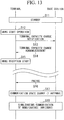
- FIGS. 13 to 16 are sequence diagrams showing processes between the base station and the terminal 200 according to the embodiments of the present invention.
- the base station checks the terminal capacity of the terminal 200.
- a connection scheme between the terminal and the base station is determined based on whether 4x4 MIMO communication is possible, whether 2x2 MIMO communication is possible, or whether only the reception capacity of one antenna is provided, and based on a network state at the time, contractual coverage of a user, and the like in addition to the terminal capacity, and communication is established in the determined scheme.
- the capacity of the terminal 200 is different according to whether or not an MBMS signal is received.
- the base station is notified of terminal capacity information and an appropriate call connection is made.
- FIG. 13 is a sequence diagram showing a process when MBMS signal reception from the base station is started during the standby state of the terminal 200.
- the base station registers a location of the terminal 200 for unicast communication. For example, if there is an incoming signal to the terminal 200, the terminal 200 waits in a state in which a call connection is possible based on a notification by paging or the like.
- the terminal 200 is in a state in which MIMO communication is possible.
- it is in a state in which 2x2 MIMO communication is possible based on terminal capacity notified upon location registration.
- 4x4 MIMO is set as the maximum capacity upon location registration of the terminal 200.
- terminal 200 and the base station perform the unicast communication in this state, user data corresponding to the 2x2 MIMO communication is transmitted from the terminal 200 to the base station when the base station communicates with the terminal 200. Thereby, the 2x2 MIMO communication can be performed between the base station and the terminal 200.
- step S12 if a user of the terminal 200 performs an MBMS start operation (step S12), one system of two communication systems is used for MBMS signal _ reception. Thus, subsequently, the unicast communication needs to perform communication using one antenna and the base station needs to be notified thereof.
- the base station transmits user data as data directed to the terminal 200 of the 2x2 MIMO communication as maximum communication capacity.
- the terminal 200 capable of using only one antenna may not perform normal unicast communication.
- the terminal 200 temporarily suspends the MBMS start process.
- the terminal 200 transmits control data (also referred to as a terminal capacity change notification message) to the base station to notify the base station of a terminal capacity change (step S13).
- the terminal capacity change notification message includes data indicating the maximum capacity capable of being used by the terminal 200 at the time.
- one system of the two communication systems is used in the MBMS.
- the terminal 200 since it is only possible to perform transmission/reception using one antenna, the terminal 200 notifies the base station of the capacity of one antenna.
- the base station receives the terminal capacity change notification from the terminal 200. Thereby, the base station can recognize the fact that the terminal 200 has the capacity of 2x2 MIMO communication as the maximum communication capacity, but only one antenna can be used based on an operation state of the terminal after the message reception.
- the base station changes the maximum capacity to one antenna when communication of the terminal 200 is performed. If the change process is completed, the base station transmits, to the terminal 200, control data (also referred to as a terminal capacity change acknowledgement message) to notify the terminal 200 of the fact that the terminal capacity change is acknowledged (step S14).
- control data also referred to as a terminal capacity change acknowledgement message
- the terminal capacity change acknowledgement message includes capacity by which communication with the base station is performed if the terminal 200 communicates with the base station after the message reception, and a setting timing thereof.
- the terminal capacity change acknowledgement message includes data indicating that communication is performed using one antenna.
- a timing indicating the next communication start time as a switching timing is set so that an operation is performed using one antenna when the next communication is performed.
- the terminal 200 When the terminal capacity change acknowledgement message is received from the base station, the terminal 200 completes unicast communication. Since the 2x2 MIMO communication is set as the terminal capacity upon location registration, the control data notification thereof can also perform the 2x2 MIMO communication. However, the communication is data communication for a small amount of only the control data, and accordingly, when the base station transmits the terminal capacity change acknowledgement message, the base station can designate a timing when an operation is performed using one antenna, and the terminal 200 can perform communication using the antenna after the designated timing.
- the terminal 200 starts to receive the MBMS (step S15). In particular, if no unicast communication is generated, the terminal 200 receives an MBMS signal and also checks paging as to whether or not there is an incoming signal directed to its own terminal as a unicast signal at a predetermined timing (step S16).
- the paging timing depends upon the settings of the base station, and thus is generally set to from about several seconds to several tens of seconds.
- the terminal 200 performs a paging reception process for unicast signals to determine whether or not there is an incoming signal directed to its own terminal at a ratio of about once every several seconds to several tens of seconds. If there is no incoming signal directed to its own terminal, the terminal 200 iterates the process.
- the terminal 200 receives paging through the unicast signals, for example, if a voice call is received, the terminal 200 performs a voice call connection process. Since the base station is notified of the operation of one antenna by the terminal capacity change notification, a voice communication connection by the unicast communication is made using the terminal 200 of one antenna (step S17).
- the terminal 200 can be connected to the voice call during MBMS signal reception. For example, even when video data or the like is received by MBMS communication, the terminal 200 can check an incoming signal of voice communication by the unicast communication, and perform the voice communication (step S18).
- an MBMS data process depends upon an application software process retained by the terminal 200. For example, it is possible to perform voice communication using an earphone/microphone and to continuously watch image data on a display of the terminal. Alternatively, the user can later watch data by storing the data in a memory embedded in the terminal 200 or an external memory such as an inserted SD card. For example, it is possible to perform packet communication such as a TV phone call, mail, or the like as the unicast communication as well as the voice communication.
- FIG. 14 is a sequence diagram showing a process of performing a terminal capacity notification from the terminal 200 to the base station at a timing different from that described with reference to FIG. 13 .
- the terminal 200 communicates only control data, communication is performed using one antenna regardless of the capacity of the terminal 200 differently from FIG. 13 .
- synchronization of the base station with the terminal 200 is established and user data is communicated, high-speed data communication using MIMO is performed.
- the terminal 200 does not immediately transmit a terminal capacity change notification to the base station. If the user performs an MBMS reception operation (step S22), the terminal 200 allocates one reception system for MBMS signal reception, allocates another system for unicast signal reception, and starts the MBMS signal reception (step S23).
- the terminal 200 checks paging at a predetermined interval as to determine whether or not there is an incoming signal directed to its own terminal at a receiver of a unicast signal as in the case in FIG. 13 (step S24).
- the paging is transmitted from the base station to the terminal 200 as data capable of being received using one antenna even when the terminal 200 has the capacity of 2x2 MIMO communication, and is not affected by reception of the MBMS signal.
- the terminal 200 transmits the terminal capacity change notification to the base station (step S25).
- the base station transmits/receives a signal to/from the terminal 200 which performs communication of only control data, using one antenna. In this case, no problem occurs in the communication of control data even in a state in which the terminal 200 receives the MBMS. If the terminal 200 transmits the terminal capacity change notification message to the base station, the message is received by the base station, which performs the unicast communication.
- the base station checks content of the message and directly determines that transmission/reception is performed using one antenna.
- the base station notifies the terminal 200 of the determination result using the terminal capacity change acknowledgement message (step S26).
- the terminal 200 continues transmission/reception using one antenna based on the determination result included in the terminal capacity change acknowledgement message (step S27), and establishes a unicast communication.
- the terminal 200 can perform the unicast communication during the MBMS signal reception (step S28).
- the terminal 200 receives the MBMS in this example, but the base station determines that an operation is possible as the MIMO for two antennas by the terminal capacity change notification only if unicast communication is performed.
- the terminal capacity change acknowledgement message the terminal 200 is notified of the determination result of the operation of the two antennas and an operation start timing thereof.
- the terminal can be changed to 2 ⁇ 2 MIMO communication at the operation start timing included in the terminal capacity change acknowledgement and can implement high-speed communication using MIMO.
- FIG. 15 is a sequence diagram showing a process when the MBMS is started by the terminal 200 during the unicast communication. For example, this is the case where a service of providing video data or the like is provided by the MBMS or the case where a reservation for receiving and recording certain video data is made using a timer or the like in the terminal 200.
- the terminal 200 If the terminal 200 is performing voice communication using MIMO communication (step S31), the terminal 200 starts an MBMS start process when an MBMS reception time is reached (step S32). If an MBMS start request is generated, the process is suspended and the terminal 200 transmits a terminal capacity change notification message to the base station (step S33).
- Signal transmission/reception is performed by 2 ⁇ 2 MIMO communication during the unicast communication, but the base station determines that a change to one antenna is necessary by the message transmission.
- the terminal 200 is notified of the determination result and a change timing by the terminal capacity change acknowledgement message (step S34).
- the terminal 200 checks that a change to one antenna is permitted from the terminal capacity change acknowledgement, and makes a change to the reception using one antenna at a designated timing (step S35).
- one reception system can be used for MBMS reception and the terminal 200 starts the MBMS reception (step S36).
- the terminal 200 can simultaneously receive an MBMS signal and unicast signals even when the MBMS reception is necessary during the unicast communication (step S37).
- FIG. 16 is a sequence diagram showing a process when the MBMS signal reception is terminated during simultaneous communication of the unicast communication and the MBMS communication. If the MBMS signal reception is completed in the case where the terminal 200 simultaneously performs the MBMS communication and the unicast communication with the base station (step S41), high-speed communication can be performed when the 2x2 MIMO communication is performed as the unicast communication. Thus, when an MBMS stop process is requested by an operation of the user of the terminal 200, the terminal 200 performs the MBMS stop process (step S42).
- the terminal 200 is in a state in which the 2x2 MIMO communication can be performed.
- the terminal 200 requests a change of an operation state by a terminal capacity change notification to the base station (step S43). If the terminal capacity change notification is received from the terminal 200, the base station determines that the terminal 200 is operable in the 2x2 MIMO communication. The base station notifies the terminal 200 of a communication state change to the 2x2 MIMO communication and a change timing in a terminal capacity change acknowledgement message (step S44).
- the terminal 200 checks that the base station permits MIMO reception by the terminal capacity change acknowledgement, and performs switching to the 2x2 MIMO communication at a designated timing (step S45). Thereafter, the terminal 200 can perform high-speed communication by performing an operation in the 2x2 MIMO communication.
- the above example shows a process when the terminal 200 receives incoming signals. If the terminal 200 transmits a call, a call operation of the user is performed instead of paging. In the other operation, it is possible to make a change to a simultaneous communication state of unicast communication and MBMS communication according to the above-described procedure.
- the notification toward the base station can be performed by setting a parameter for changing the number of reception systems using a normal call control message, and the base station can notify the terminal of a communication state change and a change timing using the normal call control message.
- switching can be appropriately performed even when setting of MIMO or a single antenna is changed between the base station, which provides a unicast service, and the terminal 200 by the terminal 200 notifying the base station of the terminal capacity of the terminal 200. Even when the terminal 200 switches a transmission/reception method of MIMO or a single antenna during communication, the communication can be continuously performed.
- the terminal 200 If the terminal capacity of its own terminal is changed, the terminal 200 notifies the base station of a terminal capacity change. If the terminal capacity change is notified from the terminal 200, the base station switches a unicast signal transmission method to an appropriate method of MIMO or a single antenna. Thereby, it is possible to appropriately switch the setting of the MBMS, the MIMO, or the single antenna between the base station, which provides the unicast service, and the terminal.
- the terminal 200 If the base station notifies the terminal 200 of a change of unicast signal transmission and MBMS signal transmission, the terminal 200 is notified of change permission information for permitting the change and timing information indicating a change timing. Thereby, even when the unicast communication is being performed between the base station and the terminal 200, it is possible to change a communication scheme according to the terminal capacity of the terminal.
- the timing information includes a frame number, a slot number, or the like.
- base station 100a as in FIG. 2 has been described in each embodiment described above, but the present invention is not limited thereto.
- base stations 100a-1 and 100a-2 of the configurations shown in FIGS. 17A and 17B can be used.
- the same reference symbols are assigned to parts in FIGS. 17A and 17B having the same configurations as those in FIG. 2 , and descriptions thereof are omitted.
- the base station 100a-1 in FIG. 17A has an antenna unit 10-1, a transmission unit 11, and a control unit 13.
- the base station 100a-1 transmits an MBMS signal to the terminal 200 by performing the process described with reference to FIG. 2 .
- the base station 100a-2 in FIG. 17B has antenna units 10-2 and 10-3, a transmission unit 11, a reception unit 12, a control unit 13, and duplexers 14-1 and 14-2.
- the base station 100a-2 transmits unicast signals to the terminal 200 by performing the process described with reference to FIG. 2 .
- a program for implementing a function of each part of a base station or a terminal according to each embodiment described above may be recorded on a computer-readable recording medium.
- the base station or the terminal may be controlled by reading the program recorded on this recording medium into a computer system.
- the "computer system” may also include an operating system (OS) and hardware such as peripheral devices.
- OS operating system
- the "computer readable recording medium” is a portable medium such as a flexible disc, magneto-optical disc, ROM or CD-ROM, and a storage device, such as a hard disk, built in the computer system. Furthermore, the “computer readable recording medium” may also include a medium that dynamically holds a program for a short period of time, such as a communication line when a program is transmitted via a network such as the Internet or a communication circuit such as a telephone circuit, and a medium that holds a program for a fixed period of time, such as a volatile memory in a computer system serving as a server or client in the above situation.
- the program may be one for implementing part of the above functions, or the above functions may be implemented in combination with a program already recorded on the computer system.
Landscapes
- Engineering & Computer Science (AREA)
- Signal Processing (AREA)
- Computer Networks & Wireless Communication (AREA)
- Mobile Radio Communication Systems (AREA)
Claims (8)
- Drahtloses Kommunikationssystem, aufweisend ein Endgerät (200) und eine Basisstation (100a), die an das Endgerät (200) Unicast-Signale und ein Multicast-Signal sendet,
wobei die Basisstation (100a) aufweist:eine Antenneneinheit (10-1), die dafür konfiguriert ist, das Multicast-Signal an das Endgerät (200) zu senden,Antenneneinheiten (10-2, 10-3), die dafür konfiguriert sind,an das Endgerät (200) einem Multiple-Input-Multiple-Output, MIMO, entsprechende Unicast-Signale unter Verwendung des MIMO zu senden, wenn das Endgerät (200) die dem MIMO entsprechenden Unicast-Signale empfängt, undan das Endgerät (200) die Unicast-Signale für eine Antenneneinheit (20-1) des Endgeräts (200) zu senden, wenn das Endgerät (200) die Unicast-Signale für eine Antenneneinheit (20-1) und das Multicast-Signal empfängt, undwobei das Endgerät (200) aufweist:Antenneneinheiten (20-1, 20-2), die dafür konfiguriert sind, von den Antenneneinheiten (10-2, 10-3) der Basisstation (100a) die dem MIMO entsprechenden Unicast-Signale unter Verwendung des MIMO zu empfangen, wenn das Endgerät (200) die dem MIMO entsprechenden Unicast-Signale empfängt; wobeieine Antenneneinheit (20-2) der Antenneneinheiten (20-1, 20-2) des Endgeräts (200) dafür konfiguriert ist,von den Antenneneinheiten (10-2, 10-3) der Basisstation (100a) die Unicast-Signale zu empfangen, wenn das Endgerät (200) die dem MIMO entsprechenden Unicast-Signale empfängt, undvon einer ersten Antenneneinheit (10-1) der Basisstation (100a) das Multicast-Signal zu empfangen, wenn das Endgerät (200) die Unicast-Signale für die eine Antenneneinheit (20-1) und das Multicast-Signal empfängt,das Endgerät (200) an die Basisstation (100a) Steuerungsdaten sendet, welche Daten enthalten, die eine maximale Kapazität angeben, die von dem Endgerät (200) genutzt werden kann, unddas Endgerät (200), das nur eine Kommunikation über Unicast-Signale durchführt, das Multicast-Signal nicht empfängt. - Drahtloses Kommunikationssystem nach Anspruch 1, wobei
das Endgerät (200) eine Versatz-Abschätzungseinheit (2204) aufweist, die dafür konfiguriert ist, einen Frequenzfehler zwischen der Basisstation (100a) und dem Endgerät (200) abzuschätzen, indem Referenzsignale genutzt werden, die in den Unicast-Signalen enthalten sind, wenn die Unicast-Signale für eine Antenneneinheit und das Multicast-Signal empfangen werden, und die dafür konfiguriert ist, den Frequenzfehler abzuschätzen, indem ein Referenzsignal genutzt wird, das in dem Multicast-Signal enthalten ist, wenn nur das Multicast-Signal empfangen wird; und
die Versatz-Abschätzungseinheit (2204) dafür konfiguriert ist, basierend auf dem abgeschätzten Frequenzfehler eine Frequenz der Basisstation (100a) mit derjenigen des Endgeräts (200) zu synchronisieren. - Drahtloses Kommunikationssystem nach Anspruch 1, wobei das Endgerät ferner aufweist:
eine Steuerungseinheit (23), die dafür konfiguriert ist, die eine Antenneneinheit (20-1), die die Unicast-Signale für eine Antenneneinheit empfängt, das Multicast-Signal empfangen zu lassen und die Antenneneinheit (20-2), die das Multicast-Signal empfängt, die Unicast-Signale für eine Antenneneinheit empfangen zu lassen, wenn eine erste Empfangsqualität der einen Antenneneinheit (20-1), die die Unicast-Signale für eine Antenneneinheit empfängt, höher ist als eine zweite Empfangsqualität der Antenneneinheit (20-2), die das Multicast-Signal empfängt. - Drahtloses Kommunikationssystem nach Anspruch 1, wobei das Endgerät (200) dafür konfiguriert ist, der Basisstation (100a) eine Änderung der Endgerätkapazität mitzuteilen, wenn eine Endgerätkapazität seines eigenen Endgeräts (200) geändert wird, und
die Basisstation (100a) dafür konfiguriert ist, eine Unicast-Signalübertragung und eine Multicast-Signalübertragung zu wechseln bzw. zu ändern, wenn vom Endgerät (200) eine Änderung der Endgerätkapazität mitgeteilt wird. - Drahtloses Kommunikationssystem nach Anspruch 4, wobei die Basisstation (100a) dafür konfiguriert ist, dem Endgerät (200) die Änderung der Unicast-Signalübertragung und der Multicast-Signalübertragung mitzuteilen.
- Drahtloses Kommunikationssystem nach Anspruch 5, wobei die Basisstation (100a) dafür konfiguriert ist, dem Endgerät (200) eine Information einer Änderungsgenehmigung, um die Änderung zu genehmigen, und eine Zeitpunktinformation, die einen Änderungszeitpunkt angibt, mitzuteilen, wenn dem Endgerät (200) die Änderung der Unicast-Signalübertragung und der Multicast-Signalübertragung mitgeteilt wird.
- Endgerät (200), das dafür konfiguriert ist, mit einer Basisstation (100a) zu kommunizieren, die an das Endgerät (200) Unicast-Signale und ein Multicast-Signal sendet,
wobei das Endgerät (200) aufweist:Antenneneinheiten (20-1, 20-2), die dafür konfiguriert sind, von Antenneneinheiten (10-2, 10-3) der Basisstation (100a) die einem Mulitple-Input-Multiple-Output, MIMO, entsprechenden Unicast-Signale unter Verwendung des MIMO zu empfangen, wenn das Endgerät (200) die dem MIMO entsprechenden Unicast-Signale empfängt; wobeieine Antenneneinheit (20-1) der Antenneneinheiten (20-1, 20-2) des Endgeräts (200) dafür konfiguriert ist,von den Antenneneinheiten (10-2, 10-3) der Basisstation (100a) die Unicast-Signale zu empfangen, wenn das Endgerät (200) die dem MIMO entsprechenden Unicast-Signale empfängt, undvon der Antenneneinheit (10-1) der Basisstation (100a) das Multicast-Signal zu empfangen, wenn das Endgerät (200) die Unicast-Signale für die eine Antenneneinheit (20-1) und das Multicast-Signal empfängt,wobei das Endgerät (200) an die Basisstation (100a) Steuerungsdaten sendet, welche Daten enthalten, die eine maximale Kapazität angeben, die von dem Endgerät (200) genutzt werden kann, unddas Endgerät (200), das nur eine Kommunikation über Unicast-Signale durchführt, das Multicast-Signal nicht empfängt. - Verfahren zur drahtlosen Kommunikation, das ein Endgerät (200) und eine Basisstation (100a) nutzt, die an das Endgerät (200) Unicast-Signale und ein Multicast-Signal sendet,
wobei das Verfahren zur drahtlosen Kommunikation aufweist:Senden, mittels einer Antenneneinheit (10-1) der Basisstation (100a), des Multicast-Signals an das Endgerät (200);Senden, mittels Antenneneinheiten (10-2, 10-3) der Basisstation (100a), von einem Multiple-Input-Multiple-Output, MIMO, entsprechenden Unicast-Signalen unter Verwendung des MIMO an das Endgerät (200), wenn das Endgerät (200) die dem MIMO entsprechenden Unicast-Signale empfängt;Senden, mittels der Antenneneinheiten (10-2, 10-3) der Basisstation (100a), der Unicast-Signale für eine Antenneneinheit (20-1) des Endgeräts (200) an das Endgerät (200), wenn das Endgerät (200) die Unicast-Signale für eine Antenneneinheit (20-1) und das Multicast-Signal empfängt;Empfangen, mittels Antenneneinheiten (20-1, 20-2) des Endgeräts (200) von den Antenneneinheiten (10-2, 10-3) der Basisstation (100a), der dem MIMO entsprechenden Unicast-Signale unter Verwendung des MIMO, wenn das Endgerät (200) die dem MIMO entsprechenden Unicast-Signale empfängt;Empfangen, mittels einer Antenneneinheit (20-2) der Antenneneinheiten (20-1, 20-2) des Endgeräts (200) von den Antenneneinheiten (10-2, 10-3) der Basisstation (100a), der Unicast-Signale, wenn das Endgerät (200) die dem MIMO entsprechenden Unicast-Signale empfängt; undEmpfangen, von der Antenneneinheit (10-1) der Basisstation (100a), des Multicast-Signals, wenn das Endgerät (200) die Unicast-Signale für die eine Antenneneinheit (20-1) und das Multicast-Signal empfängt, wobeidas Endgerät (200) an die Basisstation (100a) Steuerungsdaten sendet, welche Daten enthalten, die eine maximale Kapazität angeben, die von dem Endgerät (200) genutzt werden kann, unddas Endgerät (200), das nur eine Kommunikation über Unicast-Signale durchführt, das Multicast-Signal nicht empfängt.
Applications Claiming Priority (2)
| Application Number | Priority Date | Filing Date | Title |
|---|---|---|---|
| JP2008177946 | 2008-07-08 | ||
| PCT/JP2009/062473 WO2010005036A1 (ja) | 2008-07-08 | 2009-07-08 | 通信システム、受信装置及び通信方法 |
Publications (3)
| Publication Number | Publication Date |
|---|---|
| EP2299772A1 EP2299772A1 (de) | 2011-03-23 |
| EP2299772A4 EP2299772A4 (de) | 2016-05-18 |
| EP2299772B1 true EP2299772B1 (de) | 2020-12-02 |
Family
ID=41507148
Family Applications (1)
| Application Number | Title | Priority Date | Filing Date |
|---|---|---|---|
| EP09794480.5A Not-in-force EP2299772B1 (de) | 2008-07-08 | 2009-07-08 | Kommunikationssystem, empfangseinrichtung und kommunikationsverfahren |
Country Status (5)
| Country | Link |
|---|---|
| US (1) | US8687537B2 (de) |
| EP (1) | EP2299772B1 (de) |
| JP (1) | JP5459638B2 (de) |
| CN (1) | CN102057743B (de) |
| WO (1) | WO2010005036A1 (de) |
Families Citing this family (24)
| Publication number | Priority date | Publication date | Assignee | Title |
|---|---|---|---|---|
| KR101443618B1 (ko) * | 2006-10-30 | 2014-09-23 | 엘지전자 주식회사 | 랜덤 접속 채널 메시지 응답 방법, 랜덤 접속 채널 메시지전송 방법 및 이를 지원하는 이동통신 단말 |
| EP2552072A4 (de) * | 2010-03-26 | 2015-08-26 | Alcatel Lucent | Verfahren und vorrichtung zur wiederverwendung von mbsfn-subframes |
| JP5033219B2 (ja) * | 2010-04-30 | 2012-09-26 | 株式会社バッファロー | 中継装置、通信装置、通信システム、中継方法、フレーム受信方法、及びそのプログラム |
| US8780876B2 (en) * | 2010-08-13 | 2014-07-15 | Intel Corporation | Delivery of multicast and broadcast services concurrently with unicast data |
| US8648713B2 (en) * | 2010-09-09 | 2014-02-11 | Qualcomm Incorporated | Apparatus and method for enabling an automotive module device indicator in a wireless communication system |
| US8995291B2 (en) * | 2011-06-10 | 2015-03-31 | Qualcomm Incorporated | Tracking loop design for unicast and multicast/broadcast signals |
| WO2013024522A1 (ja) * | 2011-08-12 | 2013-02-21 | 富士通株式会社 | 無線通信システム及び通信方法 |
| US9843938B2 (en) | 2012-08-31 | 2017-12-12 | Lg Electronics Inc. | Method and apparatus for virtualizing antenna in wireless communication system |
| US10219245B2 (en) * | 2013-07-01 | 2019-02-26 | Nec Corporation | Method for providing multicast/broadcast service continuity for mobile terminals |
| US9143206B2 (en) * | 2014-02-04 | 2015-09-22 | Qualcomm Incorporated | Antenna selection with eMBMS |
| WO2015125902A1 (ja) * | 2014-02-21 | 2015-08-27 | 京セラ株式会社 | Mbms制御方法、ユーザ端末、及び基地局 |
| US9973362B2 (en) * | 2014-03-07 | 2018-05-15 | Huawei Technologies Co., Ltd. | Common broadcast channel low PAPR signaling in massive MIMO systems |
| US10630599B2 (en) | 2014-09-19 | 2020-04-21 | Sharp Kabushiki Kaisha | Terminal device, base station apparatus, and communication method |
| WO2016043018A1 (ja) * | 2014-09-19 | 2016-03-24 | シャープ株式会社 | 端末装置、基地局装置、および通信方法 |
| CN106230545B (zh) * | 2015-07-31 | 2020-08-11 | 北京智谷睿拓技术服务有限公司 | 确定信道质量的方法及其装置 |
| WO2017102114A1 (en) | 2015-12-15 | 2017-06-22 | Telefonaktiebolaget Lm Ericsson (Publ) | Paging in a group communications system |
| US9882761B2 (en) * | 2016-03-07 | 2018-01-30 | Samsung Electronics Co., Ltd | System and method for enhanced channel estimation using tap-dependent frequency offset (FO) estimation |
| JP6919213B2 (ja) * | 2017-02-15 | 2021-08-18 | 日本電気株式会社 | 通信機、通信システム、通信方法、およびプログラム |
| MX2019011315A (es) * | 2017-03-22 | 2019-11-12 | Guangdong Oppo Mobile Telecommunications Corp Ltd | Metodo y dispositivo de comunicacion inalambrica. |
| CN109547944A (zh) * | 2017-09-21 | 2019-03-29 | 华为技术有限公司 | 数据传输的方法及装置 |
| KR102786144B1 (ko) * | 2019-08-21 | 2025-03-27 | 삼성디스플레이 주식회사 | 다중 입력 다중 출력 통신을 수행하는 디스플레이 장치, 및 통신 시스템 |
| JP7795392B2 (ja) * | 2022-03-25 | 2026-01-07 | シャープ株式会社 | 端末装置及び基地局装置 |
| JP7751854B2 (ja) * | 2022-08-04 | 2025-10-09 | Ntt株式会社 | 基地局装置、無線通信システム、制御装置、及び無線通信方法 |
| JP2025047797A (ja) * | 2023-09-21 | 2025-04-03 | Kddi株式会社 | 中継デバイスを端末装置の拡張アンテナとして用いる無線通信システムにおける、端末装置、制御方法、およびプログラム |
Family Cites Families (16)
| Publication number | Priority date | Publication date | Assignee | Title |
|---|---|---|---|---|
| EP1602237A1 (de) * | 2003-03-11 | 2005-12-07 | Thomson Licensing | Heim-video-netzwerk |
| JP2005277787A (ja) | 2004-03-24 | 2005-10-06 | Casio Comput Co Ltd | 通信端末装置 |
| WO2005125116A1 (en) * | 2004-06-22 | 2005-12-29 | Telefonaktiebolaget Lm Ericsson (Publ) | Network feedback method and device |
| JP4765322B2 (ja) | 2005-01-21 | 2011-09-07 | ソニー株式会社 | 無線通信システム、無線通信装置及び無線通信方法、並びにコンピュータ・プログラム |
| JP4463780B2 (ja) * | 2005-06-14 | 2010-05-19 | 株式会社エヌ・ティ・ティ・ドコモ | 送信装置および送信方法 |
| JP5002215B2 (ja) | 2005-08-24 | 2012-08-15 | パナソニック株式会社 | Mimo受信装置及びmimo受信方法 |
| US8942153B2 (en) * | 2005-09-30 | 2015-01-27 | Lg Electronics Inc. | Method for transmitting and receiving data using a plurality of carriers |
| WO2007074371A2 (en) * | 2005-12-27 | 2007-07-05 | Nokia Corporation | Apparatus, method and computer program product providing frequency domain multiplexed multicast and unicast transmissions |
| JP4451400B2 (ja) | 2006-01-18 | 2010-04-14 | 株式会社エヌ・ティ・ティ・ドコモ | 送信装置及び送信方法 |
| AU2007200185A1 (en) * | 2006-02-08 | 2007-08-23 | Nec Australia Pty Ltd | Delivery of multicast and uni-cast services in an OFDMA system |
| JP4447575B2 (ja) | 2006-05-01 | 2010-04-07 | 株式会社エヌ・ティ・ティ・ドコモ | 送信装置及び送信方法 |
| JP4531722B2 (ja) | 2006-05-01 | 2010-08-25 | 株式会社エヌ・ティ・ティ・ドコモ | ユーザ装置、送信方法及び移動通信システム |
| US8660046B2 (en) | 2006-08-09 | 2014-02-25 | Mitsubishi Electric Corporation | Data communications method and mobile communications system |
| GB0619266D0 (en) * | 2006-09-29 | 2006-11-08 | Nokia Corp | Communication on a plurality of carriers |
| WO2008043078A2 (en) | 2006-10-03 | 2008-04-10 | Qualcomm Incorporated | Method and apparatus for handling user equipment capability information |
| JP4215169B2 (ja) | 2007-01-19 | 2009-01-28 | 日本電波工業株式会社 | 無線機 |
-
2009
- 2009-07-08 CN CN200980121046.6A patent/CN102057743B/zh active Active
- 2009-07-08 WO PCT/JP2009/062473 patent/WO2010005036A1/ja not_active Ceased
- 2009-07-08 EP EP09794480.5A patent/EP2299772B1/de not_active Not-in-force
- 2009-07-08 JP JP2010519807A patent/JP5459638B2/ja active Active
- 2009-07-08 US US13/000,297 patent/US8687537B2/en active Active
Non-Patent Citations (1)
| Title |
|---|
| None * |
Also Published As
| Publication number | Publication date |
|---|---|
| CN102057743B (zh) | 2014-10-01 |
| US20110116438A1 (en) | 2011-05-19 |
| EP2299772A4 (de) | 2016-05-18 |
| US8687537B2 (en) | 2014-04-01 |
| JPWO2010005036A1 (ja) | 2012-01-05 |
| WO2010005036A1 (ja) | 2010-01-14 |
| EP2299772A1 (de) | 2011-03-23 |
| CN102057743A (zh) | 2011-05-11 |
| JP5459638B2 (ja) | 2014-04-02 |
Similar Documents
| Publication | Publication Date | Title |
|---|---|---|
| EP2299772B1 (de) | Kommunikationssystem, empfangseinrichtung und kommunikationsverfahren | |
| US11082172B2 (en) | Methods and apparatus for multi-carrier communications with variable channel bandwidth | |
| US10681604B2 (en) | Dual SIM dual standby user equipment rat selection | |
| JP6356110B2 (ja) | 拡張された帯域幅におけるリソース割り当てのためのシステムおよび方法 | |
| CN110838898B (zh) | 一种被用于无线通信节点中的方法和装置 | |
| CN105656531B (zh) | 通信系统,通信方法,基站和通信设备 | |
| EP2797355B1 (de) | Drahtloses kommunikationsverfahren und vorrichtung | |
| CN114731667B (zh) | 终端装置、基站设备和通信方法 | |
| US8073398B2 (en) | Method and apparatus for adaptive channel utilisation | |
| KR101911853B1 (ko) | 멀티-모드 통신들을 위한 방법 및 장치들 | |
| KR20130037507A (ko) | 다중 대역 다중 셀의 운영 방법 및 장치 | |
| KR20080098282A (ko) | 직교 주파수 분할 다중 접속 시스템에서의 데이터 송수신방법 및 장치 | |
| CN103718524A (zh) | 用于单播和多播/广播信号的跟踪环设计 | |
| US8131286B2 (en) | Technique for providing broadcast services in a cellular network | |
| US20050113023A1 (en) | Method of managing communications in a network and the corresponding signal, transmitting device and destination terminal | |
| CN103518330B (zh) | 用于多网络操作的移动通信无线电接收器 | |
| CN111083784A (zh) | 一种被用于无线通信的节点中的方法和装置 | |
| US20100260127A1 (en) | System and method for robust transmission in an orthogonal frequency division multiplexed communication system | |
| US10798727B2 (en) | Method for uplink communication in a LTE cellular network | |
| CN113141240B (zh) | 一种被用于无线通信的节点中的方法和装置 | |
| CN101626577A (zh) | 通信系统的扩展广播信道及扩展的网络设备和终端设备 | |
| CN112235870A (zh) | 一种被用于无线通信的节点中的方法和装置 |
Legal Events
| Date | Code | Title | Description |
|---|---|---|---|
| PUAI | Public reference made under article 153(3) epc to a published international application that has entered the european phase |
Free format text: ORIGINAL CODE: 0009012 |
|
| 17P | Request for examination filed |
Effective date: 20101221 |
|
| AK | Designated contracting states |
Kind code of ref document: A1 Designated state(s): AT BE BG CH CY CZ DE DK EE ES FI FR GB GR HR HU IE IS IT LI LT LU LV MC MK MT NL NO PL PT RO SE SI SK SM TR |
|
| AX | Request for extension of the european patent |
Extension state: AL BA RS |
|
| DAX | Request for extension of the european patent (deleted) | ||
| RA4 | Supplementary search report drawn up and despatched (corrected) |
Effective date: 20160415 |
|
| RIC1 | Information provided on ipc code assigned before grant |
Ipc: H04W 88/06 20090101ALI20160411BHEP Ipc: H04J 99/00 20090101ALI20160411BHEP Ipc: H04J 1/00 20060101ALI20160411BHEP Ipc: H04J 11/00 20060101ALI20160411BHEP Ipc: H04B 7/04 20060101AFI20160411BHEP |
|
| STAA | Information on the status of an ep patent application or granted ep patent |
Free format text: STATUS: EXAMINATION IS IN PROGRESS |
|
| 17Q | First examination report despatched |
Effective date: 20170217 |
|
| REG | Reference to a national code |
Ref country code: DE Ref legal event code: R079 Ref document number: 602009063133 Country of ref document: DE Free format text: PREVIOUS MAIN CLASS: H04W0088020000 Ipc: H04J0001000000 |
|
| RIC1 | Information provided on ipc code assigned before grant |
Ipc: H04L 5/06 20060101ALN20200528BHEP Ipc: H04J 1/00 20060101AFI20200528BHEP Ipc: H04L 5/00 20060101ALN20200528BHEP Ipc: H04L 27/26 20060101ALI20200528BHEP Ipc: H04J 11/00 20060101ALI20200528BHEP Ipc: H04B 7/0413 20170101ALI20200528BHEP |
|
| GRAP | Despatch of communication of intention to grant a patent |
Free format text: ORIGINAL CODE: EPIDOSNIGR1 |
|
| STAA | Information on the status of an ep patent application or granted ep patent |
Free format text: STATUS: GRANT OF PATENT IS INTENDED |
|
| RIC1 | Information provided on ipc code assigned before grant |
Ipc: H04B 7/0413 20170101ALI20200624BHEP Ipc: H04L 5/00 20060101ALN20200624BHEP Ipc: H04J 11/00 20060101ALI20200624BHEP Ipc: H04L 27/26 20060101ALI20200624BHEP Ipc: H04J 1/00 20060101AFI20200624BHEP Ipc: H04L 5/06 20060101ALN20200624BHEP |
|
| INTG | Intention to grant announced |
Effective date: 20200716 |
|
| GRAS | Grant fee paid |
Free format text: ORIGINAL CODE: EPIDOSNIGR3 |
|
| GRAA | (expected) grant |
Free format text: ORIGINAL CODE: 0009210 |
|
| STAA | Information on the status of an ep patent application or granted ep patent |
Free format text: STATUS: THE PATENT HAS BEEN GRANTED |
|
| RAP1 | Party data changed (applicant data changed or rights of an application transferred) |
Owner name: SHARP KABUSHIKI KAISHA |
|
| RIN1 | Information on inventor provided before grant (corrected) |
Inventor name: TSUNEKAWA, KOICHI Inventor name: KONNO, YOSHIO Inventor name: ISHIKURA, KATSUTOSHI Inventor name: KAMENO, TOSHIAKI |
|
| AK | Designated contracting states |
Kind code of ref document: B1 Designated state(s): AT BE BG CH CY CZ DE DK EE ES FI FR GB GR HR HU IE IS IT LI LT LU LV MC MK MT NL NO PL PT RO SE SI SK SM TR |
|
| REG | Reference to a national code |
Ref country code: GB Ref legal event code: FG4D |
|
| REG | Reference to a national code |
Ref country code: AT Ref legal event code: REF Ref document number: 1342076 Country of ref document: AT Kind code of ref document: T Effective date: 20201215 Ref country code: CH Ref legal event code: EP |
|
| REG | Reference to a national code |
Ref country code: DE Ref legal event code: R096 Ref document number: 602009063133 Country of ref document: DE |
|
| REG | Reference to a national code |
Ref country code: IE Ref legal event code: FG4D |
|
| PG25 | Lapsed in a contracting state [announced via postgrant information from national office to epo] |
Ref country code: GR Free format text: LAPSE BECAUSE OF FAILURE TO SUBMIT A TRANSLATION OF THE DESCRIPTION OR TO PAY THE FEE WITHIN THE PRESCRIBED TIME-LIMIT Effective date: 20210303 Ref country code: NO Free format text: LAPSE BECAUSE OF FAILURE TO SUBMIT A TRANSLATION OF THE DESCRIPTION OR TO PAY THE FEE WITHIN THE PRESCRIBED TIME-LIMIT Effective date: 20210302 Ref country code: FI Free format text: LAPSE BECAUSE OF FAILURE TO SUBMIT A TRANSLATION OF THE DESCRIPTION OR TO PAY THE FEE WITHIN THE PRESCRIBED TIME-LIMIT Effective date: 20201202 |
|
| REG | Reference to a national code |
Ref country code: NL Ref legal event code: MP Effective date: 20201202 |
|
| REG | Reference to a national code |
Ref country code: AT Ref legal event code: MK05 Ref document number: 1342076 Country of ref document: AT Kind code of ref document: T Effective date: 20201202 |
|
| PG25 | Lapsed in a contracting state [announced via postgrant information from national office to epo] |
Ref country code: SE Free format text: LAPSE BECAUSE OF FAILURE TO SUBMIT A TRANSLATION OF THE DESCRIPTION OR TO PAY THE FEE WITHIN THE PRESCRIBED TIME-LIMIT Effective date: 20201202 Ref country code: PL Free format text: LAPSE BECAUSE OF FAILURE TO SUBMIT A TRANSLATION OF THE DESCRIPTION OR TO PAY THE FEE WITHIN THE PRESCRIBED TIME-LIMIT Effective date: 20201202 Ref country code: LV Free format text: LAPSE BECAUSE OF FAILURE TO SUBMIT A TRANSLATION OF THE DESCRIPTION OR TO PAY THE FEE WITHIN THE PRESCRIBED TIME-LIMIT Effective date: 20201202 Ref country code: BG Free format text: LAPSE BECAUSE OF FAILURE TO SUBMIT A TRANSLATION OF THE DESCRIPTION OR TO PAY THE FEE WITHIN THE PRESCRIBED TIME-LIMIT Effective date: 20210302 |
|
| PG25 | Lapsed in a contracting state [announced via postgrant information from national office to epo] |
Ref country code: HR Free format text: LAPSE BECAUSE OF FAILURE TO SUBMIT A TRANSLATION OF THE DESCRIPTION OR TO PAY THE FEE WITHIN THE PRESCRIBED TIME-LIMIT Effective date: 20201202 Ref country code: NL Free format text: LAPSE BECAUSE OF FAILURE TO SUBMIT A TRANSLATION OF THE DESCRIPTION OR TO PAY THE FEE WITHIN THE PRESCRIBED TIME-LIMIT Effective date: 20201202 |
|
| REG | Reference to a national code |
Ref country code: LT Ref legal event code: MG9D |
|
| PG25 | Lapsed in a contracting state [announced via postgrant information from national office to epo] |
Ref country code: SM Free format text: LAPSE BECAUSE OF FAILURE TO SUBMIT A TRANSLATION OF THE DESCRIPTION OR TO PAY THE FEE WITHIN THE PRESCRIBED TIME-LIMIT Effective date: 20201202 Ref country code: SK Free format text: LAPSE BECAUSE OF FAILURE TO SUBMIT A TRANSLATION OF THE DESCRIPTION OR TO PAY THE FEE WITHIN THE PRESCRIBED TIME-LIMIT Effective date: 20201202 Ref country code: RO Free format text: LAPSE BECAUSE OF FAILURE TO SUBMIT A TRANSLATION OF THE DESCRIPTION OR TO PAY THE FEE WITHIN THE PRESCRIBED TIME-LIMIT Effective date: 20201202 Ref country code: PT Free format text: LAPSE BECAUSE OF FAILURE TO SUBMIT A TRANSLATION OF THE DESCRIPTION OR TO PAY THE FEE WITHIN THE PRESCRIBED TIME-LIMIT Effective date: 20210405 Ref country code: EE Free format text: LAPSE BECAUSE OF FAILURE TO SUBMIT A TRANSLATION OF THE DESCRIPTION OR TO PAY THE FEE WITHIN THE PRESCRIBED TIME-LIMIT Effective date: 20201202 Ref country code: CZ Free format text: LAPSE BECAUSE OF FAILURE TO SUBMIT A TRANSLATION OF THE DESCRIPTION OR TO PAY THE FEE WITHIN THE PRESCRIBED TIME-LIMIT Effective date: 20201202 Ref country code: LT Free format text: LAPSE BECAUSE OF FAILURE TO SUBMIT A TRANSLATION OF THE DESCRIPTION OR TO PAY THE FEE WITHIN THE PRESCRIBED TIME-LIMIT Effective date: 20201202 |
|
| PG25 | Lapsed in a contracting state [announced via postgrant information from national office to epo] |
Ref country code: AT Free format text: LAPSE BECAUSE OF FAILURE TO SUBMIT A TRANSLATION OF THE DESCRIPTION OR TO PAY THE FEE WITHIN THE PRESCRIBED TIME-LIMIT Effective date: 20201202 |
|
| REG | Reference to a national code |
Ref country code: DE Ref legal event code: R097 Ref document number: 602009063133 Country of ref document: DE |
|
| PG25 | Lapsed in a contracting state [announced via postgrant information from national office to epo] |
Ref country code: IS Free format text: LAPSE BECAUSE OF FAILURE TO SUBMIT A TRANSLATION OF THE DESCRIPTION OR TO PAY THE FEE WITHIN THE PRESCRIBED TIME-LIMIT Effective date: 20210402 |
|
| PLBE | No opposition filed within time limit |
Free format text: ORIGINAL CODE: 0009261 |
|
| STAA | Information on the status of an ep patent application or granted ep patent |
Free format text: STATUS: NO OPPOSITION FILED WITHIN TIME LIMIT |
|
| PG25 | Lapsed in a contracting state [announced via postgrant information from national office to epo] |
Ref country code: IT Free format text: LAPSE BECAUSE OF FAILURE TO SUBMIT A TRANSLATION OF THE DESCRIPTION OR TO PAY THE FEE WITHIN THE PRESCRIBED TIME-LIMIT Effective date: 20201202 |
|
| 26N | No opposition filed |
Effective date: 20210903 |
|
| PG25 | Lapsed in a contracting state [announced via postgrant information from national office to epo] |
Ref country code: SI Free format text: LAPSE BECAUSE OF FAILURE TO SUBMIT A TRANSLATION OF THE DESCRIPTION OR TO PAY THE FEE WITHIN THE PRESCRIBED TIME-LIMIT Effective date: 20201202 Ref country code: ES Free format text: LAPSE BECAUSE OF FAILURE TO SUBMIT A TRANSLATION OF THE DESCRIPTION OR TO PAY THE FEE WITHIN THE PRESCRIBED TIME-LIMIT Effective date: 20201202 Ref country code: DK Free format text: LAPSE BECAUSE OF FAILURE TO SUBMIT A TRANSLATION OF THE DESCRIPTION OR TO PAY THE FEE WITHIN THE PRESCRIBED TIME-LIMIT Effective date: 20201202 |
|
| REG | Reference to a national code |
Ref country code: CH Ref legal event code: PL |
|
| PG25 | Lapsed in a contracting state [announced via postgrant information from national office to epo] |
Ref country code: MC Free format text: LAPSE BECAUSE OF FAILURE TO SUBMIT A TRANSLATION OF THE DESCRIPTION OR TO PAY THE FEE WITHIN THE PRESCRIBED TIME-LIMIT Effective date: 20201202 |
|
| REG | Reference to a national code |
Ref country code: BE Ref legal event code: MM Effective date: 20210731 |
|
| PG25 | Lapsed in a contracting state [announced via postgrant information from national office to epo] |
Ref country code: LI Free format text: LAPSE BECAUSE OF NON-PAYMENT OF DUE FEES Effective date: 20210731 Ref country code: CH Free format text: LAPSE BECAUSE OF NON-PAYMENT OF DUE FEES Effective date: 20210731 |
|
| PG25 | Lapsed in a contracting state [announced via postgrant information from national office to epo] |
Ref country code: IS Free format text: LAPSE BECAUSE OF FAILURE TO SUBMIT A TRANSLATION OF THE DESCRIPTION OR TO PAY THE FEE WITHIN THE PRESCRIBED TIME-LIMIT Effective date: 20210402 Ref country code: LU Free format text: LAPSE BECAUSE OF NON-PAYMENT OF DUE FEES Effective date: 20210708 |
|
| PG25 | Lapsed in a contracting state [announced via postgrant information from national office to epo] |
Ref country code: IE Free format text: LAPSE BECAUSE OF NON-PAYMENT OF DUE FEES Effective date: 20210708 Ref country code: BE Free format text: LAPSE BECAUSE OF NON-PAYMENT OF DUE FEES Effective date: 20210731 |
|
| PG25 | Lapsed in a contracting state [announced via postgrant information from national office to epo] |
Ref country code: HU Free format text: LAPSE BECAUSE OF FAILURE TO SUBMIT A TRANSLATION OF THE DESCRIPTION OR TO PAY THE FEE WITHIN THE PRESCRIBED TIME-LIMIT; INVALID AB INITIO Effective date: 20090708 Ref country code: CY Free format text: LAPSE BECAUSE OF FAILURE TO SUBMIT A TRANSLATION OF THE DESCRIPTION OR TO PAY THE FEE WITHIN THE PRESCRIBED TIME-LIMIT Effective date: 20201202 |
|
| PG25 | Lapsed in a contracting state [announced via postgrant information from national office to epo] |
Ref country code: MK Free format text: LAPSE BECAUSE OF FAILURE TO SUBMIT A TRANSLATION OF THE DESCRIPTION OR TO PAY THE FEE WITHIN THE PRESCRIBED TIME-LIMIT Effective date: 20201202 |
|
| PG25 | Lapsed in a contracting state [announced via postgrant information from national office to epo] |
Ref country code: TR Free format text: LAPSE BECAUSE OF FAILURE TO SUBMIT A TRANSLATION OF THE DESCRIPTION OR TO PAY THE FEE WITHIN THE PRESCRIBED TIME-LIMIT Effective date: 20201202 |
|
| PG25 | Lapsed in a contracting state [announced via postgrant information from national office to epo] |
Ref country code: MT Free format text: LAPSE BECAUSE OF FAILURE TO SUBMIT A TRANSLATION OF THE DESCRIPTION OR TO PAY THE FEE WITHIN THE PRESCRIBED TIME-LIMIT Effective date: 20201202 |
|
| PGFP | Annual fee paid to national office [announced via postgrant information from national office to epo] |
Ref country code: DE Payment date: 20240719 Year of fee payment: 16 |
|
| PGFP | Annual fee paid to national office [announced via postgrant information from national office to epo] |
Ref country code: GB Payment date: 20240723 Year of fee payment: 16 |
|
| PGFP | Annual fee paid to national office [announced via postgrant information from national office to epo] |
Ref country code: FR Payment date: 20240729 Year of fee payment: 16 |
|
| REG | Reference to a national code |
Ref country code: DE Ref legal event code: R119 Ref document number: 602009063133 Country of ref document: DE |
|
| GBPC | Gb: european patent ceased through non-payment of renewal fee |
Effective date: 20250708 |
|
| PG25 | Lapsed in a contracting state [announced via postgrant information from national office to epo] |
Ref country code: GB Free format text: LAPSE BECAUSE OF NON-PAYMENT OF DUE FEES Effective date: 20250708 |
|
| PG25 | Lapsed in a contracting state [announced via postgrant information from national office to epo] |
Ref country code: DE Free format text: LAPSE BECAUSE OF NON-PAYMENT OF DUE FEES Effective date: 20260203 |
|
| PG25 | Lapsed in a contracting state [announced via postgrant information from national office to epo] |
Ref country code: FR Free format text: LAPSE BECAUSE OF NON-PAYMENT OF DUE FEES Effective date: 20250731 |