EP2301647B1 - Washing device and washing method for marine exhaust flue gases - Google Patents
Washing device and washing method for marine exhaust flue gases Download PDFInfo
- Publication number
- EP2301647B1 EP2301647B1 EP08757715.1A EP08757715A EP2301647B1 EP 2301647 B1 EP2301647 B1 EP 2301647B1 EP 08757715 A EP08757715 A EP 08757715A EP 2301647 B1 EP2301647 B1 EP 2301647B1
- Authority
- EP
- European Patent Office
- Prior art keywords
- flue gas
- scrubbing
- housing
- seawater
- ship
- Prior art date
- Legal status (The legal status is an assumption and is not a legal conclusion. Google has not performed a legal analysis and makes no representation as to the accuracy of the status listed.)
- Not-in-force
Links
- 239000003546 flue gas Substances 0.000 title claims description 249
- 238000000034 method Methods 0.000 title description 20
- 238000005406 washing Methods 0.000 title 2
- 238000005201 scrubbing Methods 0.000 claims description 247
- UGFAIRIUMAVXCW-UHFFFAOYSA-N Carbon monoxide Chemical compound [O+]#[C-] UGFAIRIUMAVXCW-UHFFFAOYSA-N 0.000 claims description 237
- 239000007789 gas Substances 0.000 claims description 95
- 239000013535 sea water Substances 0.000 claims description 91
- 239000007788 liquid Substances 0.000 claims description 61
- 238000001816 cooling Methods 0.000 claims description 54
- XLYOFNOQVPJJNP-UHFFFAOYSA-N water Substances O XLYOFNOQVPJJNP-UHFFFAOYSA-N 0.000 claims description 31
- 238000007599 discharging Methods 0.000 claims description 24
- 239000003595 mist Substances 0.000 claims description 19
- 238000011049 filling Methods 0.000 claims description 15
- 239000000463 material Substances 0.000 claims description 8
- 229910010272 inorganic material Inorganic materials 0.000 claims description 5
- 239000011147 inorganic material Substances 0.000 claims description 4
- 239000002861 polymer material Substances 0.000 claims description 4
- 238000000926 separation method Methods 0.000 claims description 4
- 238000009826 distribution Methods 0.000 claims description 3
- RAHZWNYVWXNFOC-UHFFFAOYSA-N Sulphur dioxide Chemical compound O=S=O RAHZWNYVWXNFOC-UHFFFAOYSA-N 0.000 description 56
- 239000000243 solution Substances 0.000 description 21
- 230000005587 bubbling Effects 0.000 description 14
- 230000000694 effects Effects 0.000 description 14
- 229910052717 sulfur Inorganic materials 0.000 description 12
- 239000011593 sulfur Substances 0.000 description 12
- NINIDFKCEFEMDL-UHFFFAOYSA-N Sulfur Chemical compound [S] NINIDFKCEFEMDL-UHFFFAOYSA-N 0.000 description 10
- 238000005260 corrosion Methods 0.000 description 10
- 230000007797 corrosion Effects 0.000 description 10
- 239000003344 environmental pollutant Substances 0.000 description 9
- 231100000719 pollutant Toxicity 0.000 description 9
- 239000000295 fuel oil Substances 0.000 description 8
- 238000002156 mixing Methods 0.000 description 8
- FAPWRFPIFSIZLT-UHFFFAOYSA-M Sodium chloride Chemical compound [Na+].[Cl-] FAPWRFPIFSIZLT-UHFFFAOYSA-M 0.000 description 7
- 238000010586 diagram Methods 0.000 description 6
- 238000005516 engineering process Methods 0.000 description 6
- 238000010438 heat treatment Methods 0.000 description 5
- 238000004519 manufacturing process Methods 0.000 description 5
- -1 sulfurous acid ions Chemical class 0.000 description 5
- 239000012510 hollow fiber Substances 0.000 description 4
- 239000012528 membrane Substances 0.000 description 4
- 239000007921 spray Substances 0.000 description 4
- 229910002089 NOx Inorganic materials 0.000 description 3
- LSNNMFCWUKXFEE-UHFFFAOYSA-N Sulfurous acid Chemical compound OS(O)=O LSNNMFCWUKXFEE-UHFFFAOYSA-N 0.000 description 3
- 239000002253 acid Substances 0.000 description 3
- 230000002378 acidificating effect Effects 0.000 description 3
- 238000006243 chemical reaction Methods 0.000 description 3
- 238000005265 energy consumption Methods 0.000 description 3
- 230000007613 environmental effect Effects 0.000 description 3
- 239000000446 fuel Substances 0.000 description 3
- MWUXSHHQAYIFBG-UHFFFAOYSA-N nitrogen oxide Inorganic materials O=[N] MWUXSHHQAYIFBG-UHFFFAOYSA-N 0.000 description 3
- 229910052815 sulfur oxide Inorganic materials 0.000 description 3
- 229920000049 Carbon (fiber) Polymers 0.000 description 2
- 239000004698 Polyethylene Substances 0.000 description 2
- 239000004743 Polypropylene Substances 0.000 description 2
- 229920000122 acrylonitrile butadiene styrene Polymers 0.000 description 2
- 239000004676 acrylonitrile butadiene styrene Substances 0.000 description 2
- 239000004917 carbon fiber Substances 0.000 description 2
- 239000000356 contaminant Substances 0.000 description 2
- 239000000498 cooling water Substances 0.000 description 2
- 239000003500 flue dust Substances 0.000 description 2
- 239000002184 metal Substances 0.000 description 2
- VNWKTOKETHGBQD-UHFFFAOYSA-N methane Chemical compound C VNWKTOKETHGBQD-UHFFFAOYSA-N 0.000 description 2
- 239000000203 mixture Substances 0.000 description 2
- 239000013618 particulate matter Substances 0.000 description 2
- 229920000573 polyethylene Polymers 0.000 description 2
- 229920001155 polypropylene Polymers 0.000 description 2
- 238000003303 reheating Methods 0.000 description 2
- 238000005507 spraying Methods 0.000 description 2
- LSNNMFCWUKXFEE-UHFFFAOYSA-L sulfite Chemical class [O-]S([O-])=O LSNNMFCWUKXFEE-UHFFFAOYSA-L 0.000 description 2
- XTQHKBHJIVJGKJ-UHFFFAOYSA-N sulfur monoxide Chemical compound S=O XTQHKBHJIVJGKJ-UHFFFAOYSA-N 0.000 description 2
- 239000002699 waste material Substances 0.000 description 2
- MGWGWNFMUOTEHG-UHFFFAOYSA-N 4-(3,5-dimethylphenyl)-1,3-thiazol-2-amine Chemical compound CC1=CC(C)=CC(C=2N=C(N)SC=2)=C1 MGWGWNFMUOTEHG-UHFFFAOYSA-N 0.000 description 1
- 239000005864 Sulphur Substances 0.000 description 1
- 239000000956 alloy Substances 0.000 description 1
- 239000007864 aqueous solution Substances 0.000 description 1
- QVGXLLKOCUKJST-UHFFFAOYSA-N atomic oxygen Chemical compound [O] QVGXLLKOCUKJST-UHFFFAOYSA-N 0.000 description 1
- BVKZGUZCCUSVTD-UHFFFAOYSA-N carbonic acid Chemical compound OC(O)=O BVKZGUZCCUSVTD-UHFFFAOYSA-N 0.000 description 1
- 239000000919 ceramic Substances 0.000 description 1
- 229910010293 ceramic material Inorganic materials 0.000 description 1
- 238000002485 combustion reaction Methods 0.000 description 1
- 238000005536 corrosion prevention Methods 0.000 description 1
- 230000003247 decreasing effect Effects 0.000 description 1
- 230000003009 desulfurizing effect Effects 0.000 description 1
- 239000002283 diesel fuel Substances 0.000 description 1
- TXKMVPPZCYKFAC-UHFFFAOYSA-N disulfur monoxide Inorganic materials O=S=S TXKMVPPZCYKFAC-UHFFFAOYSA-N 0.000 description 1
- 239000000428 dust Substances 0.000 description 1
- 229920006351 engineering plastic Polymers 0.000 description 1
- 238000007654 immersion Methods 0.000 description 1
- 150000002484 inorganic compounds Chemical class 0.000 description 1
- 229910021645 metal ion Inorganic materials 0.000 description 1
- 230000007935 neutral effect Effects 0.000 description 1
- JCXJVPUVTGWSNB-UHFFFAOYSA-N nitrogen dioxide Inorganic materials O=[N]=O JCXJVPUVTGWSNB-UHFFFAOYSA-N 0.000 description 1
- 229910052760 oxygen Inorganic materials 0.000 description 1
- 239000001301 oxygen Substances 0.000 description 1
- 239000002245 particle Substances 0.000 description 1
- 238000001556 precipitation Methods 0.000 description 1
- 238000002360 preparation method Methods 0.000 description 1
- 230000002265 prevention Effects 0.000 description 1
- 230000035484 reaction time Effects 0.000 description 1
- 150000003467 sulfuric acid derivatives Chemical class 0.000 description 1
- 239000002351 wastewater Substances 0.000 description 1
Images


Classifications
-
- B—PERFORMING OPERATIONS; TRANSPORTING
- B01—PHYSICAL OR CHEMICAL PROCESSES OR APPARATUS IN GENERAL
- B01D—SEPARATION
- B01D47/00—Separating dispersed particles from gases, air or vapours by liquid as separating agent
- B01D47/14—Packed scrubbers
-
- B—PERFORMING OPERATIONS; TRANSPORTING
- B01—PHYSICAL OR CHEMICAL PROCESSES OR APPARATUS IN GENERAL
- B01D—SEPARATION
- B01D53/00—Separation of gases or vapours; Recovering vapours of volatile solvents from gases; Chemical or biological purification of waste gases, e.g. engine exhaust gases, smoke, fumes, flue gases, aerosols
- B01D53/14—Separation of gases or vapours; Recovering vapours of volatile solvents from gases; Chemical or biological purification of waste gases, e.g. engine exhaust gases, smoke, fumes, flue gases, aerosols by absorption
- B01D53/1456—Removing acid components
- B01D53/1481—Removing sulfur dioxide or sulfur trioxide
-
- B—PERFORMING OPERATIONS; TRANSPORTING
- B01—PHYSICAL OR CHEMICAL PROCESSES OR APPARATUS IN GENERAL
- B01D—SEPARATION
- B01D47/00—Separating dispersed particles from gases, air or vapours by liquid as separating agent
- B01D47/02—Separating dispersed particles from gases, air or vapours by liquid as separating agent by passing the gas or air or vapour over or through a liquid bath
-
- B—PERFORMING OPERATIONS; TRANSPORTING
- B01—PHYSICAL OR CHEMICAL PROCESSES OR APPARATUS IN GENERAL
- B01D—SEPARATION
- B01D53/00—Separation of gases or vapours; Recovering vapours of volatile solvents from gases; Chemical or biological purification of waste gases, e.g. engine exhaust gases, smoke, fumes, flue gases, aerosols
- B01D53/14—Separation of gases or vapours; Recovering vapours of volatile solvents from gases; Chemical or biological purification of waste gases, e.g. engine exhaust gases, smoke, fumes, flue gases, aerosols by absorption
- B01D53/18—Absorbing units; Liquid distributors therefor
-
- B—PERFORMING OPERATIONS; TRANSPORTING
- B01—PHYSICAL OR CHEMICAL PROCESSES OR APPARATUS IN GENERAL
- B01D—SEPARATION
- B01D53/00—Separation of gases or vapours; Recovering vapours of volatile solvents from gases; Chemical or biological purification of waste gases, e.g. engine exhaust gases, smoke, fumes, flue gases, aerosols
- B01D53/34—Chemical or biological purification of waste gases
- B01D53/46—Removing components of defined structure
- B01D53/48—Sulfur compounds
- B01D53/50—Sulfur oxides
- B01D53/507—Sulfur oxides by treating the gases with other liquids
-
- B—PERFORMING OPERATIONS; TRANSPORTING
- B01—PHYSICAL OR CHEMICAL PROCESSES OR APPARATUS IN GENERAL
- B01D—SEPARATION
- B01D53/00—Separation of gases or vapours; Recovering vapours of volatile solvents from gases; Chemical or biological purification of waste gases, e.g. engine exhaust gases, smoke, fumes, flue gases, aerosols
- B01D53/34—Chemical or biological purification of waste gases
- B01D53/74—General processes for purification of waste gases; Apparatus or devices specially adapted therefor
- B01D53/77—Liquid phase processes
- B01D53/78—Liquid phase processes with gas-liquid contact
-
- B—PERFORMING OPERATIONS; TRANSPORTING
- B01—PHYSICAL OR CHEMICAL PROCESSES OR APPARATUS IN GENERAL
- B01D—SEPARATION
- B01D2252/00—Absorbents, i.e. solvents and liquid materials for gas absorption
- B01D2252/10—Inorganic absorbents
- B01D2252/103—Water
- B01D2252/1035—Sea water
-
- B—PERFORMING OPERATIONS; TRANSPORTING
- B01—PHYSICAL OR CHEMICAL PROCESSES OR APPARATUS IN GENERAL
- B01D—SEPARATION
- B01D2257/00—Components to be removed
- B01D2257/30—Sulfur compounds
- B01D2257/302—Sulfur oxides
-
- B—PERFORMING OPERATIONS; TRANSPORTING
- B01—PHYSICAL OR CHEMICAL PROCESSES OR APPARATUS IN GENERAL
- B01D—SEPARATION
- B01D2258/00—Sources of waste gases
- B01D2258/01—Engine exhaust gases
- B01D2258/012—Diesel engines and lean burn gasoline engines
-
- B—PERFORMING OPERATIONS; TRANSPORTING
- B01—PHYSICAL OR CHEMICAL PROCESSES OR APPARATUS IN GENERAL
- B01D—SEPARATION
- B01D2259/00—Type of treatment
- B01D2259/45—Gas separation or purification devices adapted for specific applications
- B01D2259/4566—Gas separation or purification devices adapted for specific applications for use in transportation means
Definitions
- This invention relates to a ship flue gas scrubbing apparatus and scrubbing method, in which seawater is used to scrub and reduce pollutant discharge, mainly sulfur dioxide, from marine shipping. It belongs to the technical fields of atmospheric environmental protection and flue gas pollution prevention and control for the marine shipping.
- Prior Art 1 a Chinese patent application No. 200710012371.1 , entitled “apparatus and method for treating ship exhausts by seawater scrubbing", published on January 16,2008.
- the technical solution is that in a hollow fiber membrane contactor used as a scrubber, the ship exhaust after dust removal pretreatment is scrubbed with seawater.
- a control system composed of a SO 2 consistency monitor, a water quality monitor and a PLC programming controller detects and records in real time the SO 2 concentration and water discharge quality in the processed ship exhaust, and controls the water discharge.
- a hollow fiber membrane contactor is used to realize the scrubbing function.
- the hollow fiber membrane can only tolerate tens of centigrade in temperature, and cannot be used for processing flue gas discharged from ship engines with a temperature as high as 200-490°C.
- Prior Art 2 US Patent No. 7,056,367 issued on June 6, 2006 , entitled “Method and apparatus for scrubbing gases, using mixing vanes”.
- This invention discloses a scrubber for exhaust gas composed of a series of nested counter-flow passages including a hot plenum having a star-shaped section.
- the Exhaust gas from the hot plenum surges through a liquid bath and flows in a reverse direction through an inclined array of flat, overlapping, spaced mixing vanes, causing turbulence in the exhaust gas and forming highly dispersed tiny bubbles, which accelerates the entry of gaseous pollutants into the scrubbing liquid.
- Mist eliminator vanes remove entrained liquids from the exhaust gases.
- the hot plenum reheats the exhaust gases to an unsaturated level.
- the scrubbing significantly and effectively reduces particulate matter and the pollutants such as sulfur dioxide and nitrogen dioxide in the exhaust gases, and reduces heat as well. The details are given hereinbelow.
- the technical solution of the invented apparatus of US 7,056,367 is a scrubber device for reducing of gaseous particulates and contaminants discharged from industrial facilities, which includes: 1) a co-axial nested inlet conduit, a hot conduit, an outlet conduit, an counter-flow passage of the exhaust gas, and a tank containing a scrubbing liquid; 2) wherein ends of the heat conduit and the outlet conduit are interconnected and immersed in the scrubbing liquid in the tank, whereby the exhaust gas passes through the liquid bath; 3) one or more mixing vanes, and one or more horizontal mist eliminator vanes; 4) said mixing vanes are located inside the immersed end of the outlet conduit, and are adapted to generate a turbulence in the exhaust gas so as to form very small bubbles; 5) said mist eliminator vanes are located downstream of the mixing vanes of the outlet conduit, so as to remove mist droplets from the exhaust gas.
- the technical solution of the invented method of US 7,056,367 is a method of scrubbing the exhaust gas to reduce particulates and gaseous contaminants and to decrease the temperature in the exhaust gas, which comprises: a) passing the exhaust gas through an extended inlet conduit; b) passing the exhaust gas in a counter-flow direction through a heat conduit surrounding the inlet conduit; c) passing the exhaust gas through a liquid bath for scrubbing, cooling, and for precipitation of the particulate matter; d) passing the exhaust gas in a counter-flow direction into an outlet conduit surrounding the heat conduit and having share a length of the wall with the heat conduit; e) passing the exhaust gas through one or more mixing vanes so as to change the direction of the gas , whereby generating a turbulence in the liquid bath, and creating (numerous) fine bubbles to form a bubble stream; f) passing the exhaust gas through one or more mist eliminator vanes to substantially eliminate any entrained bubbles or moisture; g) passing the exhaust gas along a heated surface of
- seawater scrubbing to reduce the sulfur dioxide and other pollutants in the exhaust gas mainly relies on some important conditions.
- One of the conditions is the temperature, and the higher the temperature, the worse the scrubbing effect.
- Another condition is the gas-liquid contact area, and the larger the contact area, the better the scrubbing effect.
- the basic technical solution in US patent No. 7,056,367 is "passing the exhaust gas through the scrubbing liquid in the tank", i.e., bubbling scrubbing in which the high temperature exhaust gas is scrubbed and cooled, and the gas-liquid contact surface is enlarged by "mixed vanes".
- the "passing exhaust gases through the scrubbing liquid in the tank” in the invention is the technical solution of bubbling scrubbing, which has the following shortcomings when used for scrubbing the high temperature exhaust gas of ship by seawater.
- the invention adopts a nested heat exchanger of the "heat conduit" type under the condition of scrubbing the ship exhaust gas with seawater.
- the real temperature of the reheated exhaust will not only be not higher than the acid dew point by 30°C, but also be significantly lower than the dew point.
- the problem is that in the range of the temperature not higher than the dew point, the corrosion gets more serious when the exhaust temperature is higher.
- the purpose of this technical solution of this invention is to prevent the corrosion, but the re-heating method for increasing the exhaust temperature may only aggravate the corrosion. The result seems against the inventive purpose.
- the invention has been experimented on ships for many years.
- US 3,285,711 discloses a system for the preparation of inert flue gases comprising in combination, means for producing flue gases and means for treating the flue gases and removing oxides of sulphur therefrom and for inerting a cargo tank at ambient temperature, the flue gas treating means including a scrubber first stage having an inlet adapted to be connected to a source of flue gas, a conduit arranged to be connected to a supply of water, means connected to the conduit for introducing an aqueous solution of an alkaline inorganic compound into the scrubber first stage, means for intimately contacting the flue gases with the solution; a dehumidifier second stage connected and arranged to receive the scrubbed flue gases from the first stage for removing water vapour from the flue gases, said dehumidifier second stage including separate means connected to the conduit and having cooling means therein for placing cooled water from the conduit into direct contact with the scrubbed flue gases, and means for directing the spent dehumidifying cooled water from the dehumidifier
- Prior Art 4 US 4,085,194 discloses a waste flue gas desulfurizing method in which a waste flue gas containing sulfurous acid gas is contacted directly with sea-water, whereby the sulfurous acid gas is absorbed in the sea-water and concurrently sulfites are formed in the sea-water by the reaction between the sulfurous acid ions and metal ions present in the sea-water, and then the carbonic acid component contained in the sea-water which is then in the acidic region is released therefrom by a decarbonation operation to restore the pH value of the sea-water in the neutral region, and thereafter oxygen contained in the air or from other source is introduced into the sulfite-containing sea-water to convert said sulfites into sulfates.
- the first object of the present invention is to overcome the shortcomings in the existing ship flue gas scrubbing apparatus, and to provide a highly efficient ship flue gas scrubbing apparatus adapted for ships with a high gas temperature gas and a limited space.
- the second object of the present invention is to overcome the shortcomings in the existing ship flue gas scrubbing methods, and to provide a ship flue gas scrubbing method in which the high temperature exhaust gas is cooled first and then scrubbing by fillings is performed, whereby the cooling and scrubbing are separated into two steps to respectively achieve the best results.
- the common object of the ship flue gas scrubbing apparatus and method in the present invention is to realize the good technical and economic goals, which include a high pollutant reduction efficiency, a low running cost, a long lifespan, and a guarantee that the total cost is significantly lower than the total cost saved by substituting low-sulfur fuels.
- the technical solution of the ship flue gas scrubbing apparatus of the present invention is as follow.
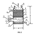
- a ship flue gas scrubbing apparatus comprising a housing (1), a scrubbing layer (7) having fillings being fixed within the housing at an upper part of the housing, a liquid collecting pool (15) with a seawater discharging outlet (16) being provided within the housing at a lower part of the housing, a flue gas leading pipe (3) for leading flue gas to be scrubbed from outside of the housing (1) into inside of the housing, is connected to a wall of the housing (1), one end of the flue gas leading pipe (3) being a flue gas inlet (3.1) outside the housing, another end of the flue gas leading pipe (3) being a flue gas leading-in port (3.2) inside the housing, the flue gas leading-in port (3.2) being located at an inner wall of the housing (1) or extends into the housing (1), and being located between the scrubbing layer (7) and the liquid collecting pool (15), a cooler (4) for cooling high temperature flue gas (2) being provided in a flue gas passage between the flue gas inlet (3.1) outside the housing of the flue
- a scrubbing layer having fillings is fixed within the housing at an upper part of the housing.
- a liquid collecting pool with a seawater discharging outlet is provided within the housing at a lower part of the housing.
- a flue gas leading pipe which guides flue gas to be scrubbed from the outside of the housing into the inside of the housing, is connected to a wall of the housing.
- One end of the flue gas leading pipe is a flue gas inlet located outside the housing.
- the other end of the flue gas leading pipe is a flue gas leading-in port located inside the housing.
- the flue gas leading-in port is located at an inner wall of the housing or extends into the housing, and is located between the scrubbing layer and the liquid collecting pool.
- a cooler for cooling high temperature flue gas is provided in a flue gas passage between the flue gas inlet outside the housing of the flue gas leading pipe and the scrubbing layer.
- a scrubbing seawater inlet is above the scrubbing layer.
- a clean gas outlet is provided at the top of the housing.
- the cooler is a cooling flow equalization layer provided between the gas leading-in port inside the housing and the scrubbing layer.
- the cooling flow equalization layer is composed of high temperature resistant components and is fixed, or installed by means of fasteners, on the inner wall of the housing.
- the cooler is a tube cooler or a sheet cooler installed on the flue gas leading pipe or in a cavity inside the pipe.
- the cooler is a spray system connected to the flue gas leading pipe or on the housing, for spraying cooling water to the high temperature flue gas.
- the gas leading-in port inside the housing is an exit of the flue gas leading pipe fixed at the bottom of the housing and extending to the inside of the housing. Facing the exit is a liquid collecting cover for preventing the scrubbing seawater from entering the flue gas leading pipe.
- the gas leading-in port inside the housing is a through hole in the side wall of the housing, or an exit of the flue gas leading pipe fixedly connected to the side wall of the housing.
- the liquid collecting pool is fixedly composed of a lower side wall of the housing, a bottom of the housing, and a pipe wall of the flue gas leading pipe or a separation plate outside the pipe wall.
- the liquid collecting pool is composed of the side wall and the bottom of the housing under a horizontal cross section where a lower edge of the flue gas leading-in port inside the housing lies.
- the material of the high temperature resistance components forming the cooling flow equalization layer is a high temperature resistant inorganic material selected from metal, ceramics or carbon fiber materials.
- the cooling flow equalization layer includes high temperature resistant fillings and a filling supporting frame.
- the supporting frame for the high temperature resistant fillings is fixed on the inner wall of the housing directly or through fasteners.
- the cooling flow equalization layer includes a high temperature resistant grid or/and a high temperature resistant perforated plate, which is fixed on the wall of the housing directly or through fasteners.
- the scrubbing layer includes fillings and a filling supporting frame.
- the filling supporting frame is fixed on the inner wall of the housing directly or through fasteners.
- the fillings in the scrubbing layer is of a polymer material selected from polypropylene, polyethylene, or ABS engineering plastics.
- a water distributor which outflows downwards the scrubbing seawater in a horizontal and even distribution pattern is fixed above the scrubber layer.
- the water distributor is composed of aligned water pipes or/and water channels.
- a mist eliminator 9 for eliminating mist drops in the exhaust gas is installed above the water distributor.
- the technical solution of the ship flue gas scrubbing method of the present invention for scrubbing, by means of seawater, the pollutants, mainly sulfur dioxide in the flue gas discharged from ships is as following.
- a leading in flue gas flue gas discharged by an engine is led into a scrubber, and the leaded-in flue gas is caused to flow upwards in the scrubber;
- the scrubbing seawater is injected into the scrubber from a scrubbing seawater entrance located above a scrubbing layer of the scrubber, and the scrubbing seawater is caused to flow downwards in the scrubber;
- scrubbing in a counter-flow way is realized by flowing the scrubbing seawater, which is injected from above the scrubber, through a scrubbing layer with fillings to contact low temperature flue gas that goes upwards; .
- d. cooling high temperature flue gas is cooled by a cooler.
- the scrubbing seawater flows downward through the cooler to reduce the temperature of the high temperature flue gas, then the cooled flue gas goes upwards to enter the scrubbing layer;
- the method of sufficiently scrubbing the low temperature flue gas going upwards is that, in the scrubbing layer, the flue gas and the scrubbing seawater is caused to contact and mix sufficiently at a gas-liquid contact surface of the fillings, and the flue gas going upwards is caused to be sufficiently scrubbed to remove the SO 2 therefrom.
- discharging the clean flue gas in the step of discharging clean flue gas, discharging the clean flue gas is that the clean flue gas is caused to pass through a mist eliminator to eliminate mist drops in the flue gas and then is discharged from the cleaned flue gas outlet.
- an operational pressure loss of the flue gas is less than 110 millimeters of water column.
- Natural seawater possesses strong abilities to dissolve and absorb sulfur dioxide, and can be used to scrub and clean flue gases, so as to eliminate sulfur dioxide and other pollutants in flue gases discharged from industrial combustion facilities.
- Practical apparatus for scrubbing flue gases with seawater is required to have a small size and a high efficiency. This is because that the ships have a limited space, the reaction time in the processing is short, the processing apparatus must have not only a high total absorptivity but also a high absorbing speed. In other words, the scrubbing and absorbing efficiency must be very high, otherwise the apparatus is not practical.
- the key processing factors are reaction temperature and contact area.
- the present invention employs the method of first cooling the high temperature flue gas, followed by scrubbing and absorbing, separating the cooling and the scrubbing and absorbing into two functional sections, respectively realizing the highest efficiency, and achieving the best overall effect.
- the total cost of the ship flue gas scrubbing apparatus and method of the present invention is significantly lower than the total cost saved by substituting the low-sulfur fuel, thereby changing the situation of lacking a practical technology for the ship emission reduction, and realizing the expectation of reducing ship pollution by means of seawater scrubbing, which has been pursued by people for a long time but has not been realized.
- the technical solution of the present invention not only realizes high efficiency, high performance, and high reliability, but also significantly reduces manufacturing cost and operational cost, and therefore, it has excellent technical and economic performance and good technical effects.
- FIG. 1 and FIG.2 1 - housing, 2 - high temperature flue gas, 3 - flue gas leading pipe, 3.1 - flue gas inlet outside the housing, 3.2 - flue gas leading-in port inside the housing, 4 - cooler, 4' - cooling flow equalization layer, 5 - low temperature flue gas, 6 - filling supporting frame, 7 - scrubbing layer, 8 - water distributor, 9 - mist eliminator, 10 - exhaust gas outlet, 11 - discharging clean flue gas, 12 - scrubbing seawater inlet pipe, 13 - scrubbing seawater, 14 - liquid collecting cover, 15 liquid collecting pool, 16 - seawater discharging pipe, 17 - discharged seawater; D - the diameter of the scrubber, which is a side length when the scrubber is rectangular; L - the height of the scrubber.
- a - leading flue gas in b - injecting scrubbing seawater, c - scrubbing, d - cooling, e - discharging the clean gas, and f - discharging the scrubbing seawater.
- FIG. 4 (the technical resolution of the US patent 7,056,367 ), 18 - gas inlet conduit and gas inlet; 19 - hot conduit; 20 - exhaust gas leading pipe; 21 - tank containing scrubbing liquid; 22 - scrubbing liquid; 23 - mixing vanes, 24 - mist eliminator vanes, 25 - mixing exhaust and scrubbing liquid in the tank, 26 - scrubbing gas re-heat area, and 27 - scrubbing liquid inlet and outlet.
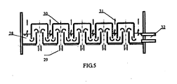
- FIG. 5 (conventional bubbling scrubber), 28 - scrubbing liquid, 29 - entering gas, 30 - bubbling hood unit, 31 - discharging gas, and 32 - inlet and outlet of scrubbing liquid.
- the flue gas leading-in port 3.2 inside the housing is the exit of the flue gas inlet pipe 3 which is fixed at the bottom of the housing 1 and extends to the inside of the housing 1.
- the flue gas leading pipe 3 is always kept above acidic seawater surface in the liquid collecting pool 15, that is to say, the flue gas does not enter the acid seawater. It is suitable for the situation where the flue gas is leaded in vertically. It includes a housing 1. a scrubbing layer 7 with fillings is fixed at the upper side inside the housing. A liquid collecting pool 15 with a seawater outlet 16 is provided at the lower side inside the housing.
- a flue gas leading pipe 3 which leads the exhaust gas to be scrubbed from the outside into the housing 1, is connected to the housing wall of the housing 1.
- One end of the flue gas leading pipe 3 is a flue gas inlet 3.1 outside the housing, the other end is the flue gas leading-in port 3.2 inside the housing.
- the gas leading-in port 3.2 inside the housing extends into the housing 1, and it is located between the scrubbing layer 7 and the liquid collecting pool 15.
- a cooler 4 used for cooling the high temperature flue gas 2 is provided in the flue gas passage between the flue gas inlet 3.1 outside the housing of the flue gas leading pipe 3 and the scrubbing layer 7.
- a scrubbing seawater inlet 12 is provided above the scrubbing layer 7.
- a purified flue gas outlet 10 is provided at the top of the housing 1.
- the cooler 4 is a cooling flow equalization layer 4' and is located between the flue gas leading-in port 3.2 inside the housing and the scrubbing layer 7.
- the cooling flow equalization layer 4' is made up of high temperature resistance components and is fixed on the inner wall of housing 1. Alternatively it can be fixed on the inner wall of housing 1 by means of fasteners.
- the cooler 4 is a tube cooler or sheet cooler installed on the flue gas leading pipe 3.
- the cooler 4 is a tube cooler or sheet cooler installed in an internal cavity of the flue gas leading pipe 3.
- the cooler 4 is a water spray system connected to the flue gas leading pipe 3 or the housing 1 for spraying cooling water to the high temperature flue gas 2.
- the water spray system can be a set of spray heads.
- the gas leading-in port 3.2 inside the housing 1 is fixed at the bottom of the housing 1 and extends to the exit of the flue gas leading pipe 3 inside the housing 1.
- a Facing the exit is a liquid collecting cover 14 for preventing the scrubbing seawater from entering the flue gas leading pipe 3.
- the gas leading-in port 3.2 inside the housing 1 is a through hole in the side wall of the housing 1, or an exit of the flue gas leading pipe 3 fixedly connected to the side wall of the housing 1.
- the liquid collecting pool 15 is composed of the lower side wall of the housing 1, the bottom of the housing 1 and the pipe wall of the flue gas leading pipe 3, or a a separation plate outside the flue gas leading pipe 3.
- the separation plate is able to prevent the pipe wall of the flue gas leading pipe 3 from corrosion.
- the high temperature resistant components that make up the cooling flow equalization layer 4' are high temperature resistant inorganic materials. In this embodiment, ceramic material is used, and metal or carbon fiber materials may also be used.
- the high temperature resistance components of the cooling flow equalization layer 4' are composed of high temperature resistant fillings and a filling supporting frame. The filling supporting frame is directly fixed, or be fixed through fasteners, on the inner wall of the housing 1.
- the cooling flow equalization layer 4' may be a high temperature resistant grid or a high temperature resistant perforated plate, or the combination of both, which can be directly fixed, or be fixed through fasteners, on the inner wall of the housing 1.
- the scrubbing layer 7 is composed of fillings and a filling supporting frame.
- the filling supporting frame is directly fixed, or be fixed through fasteners, on the inner wall of the housing 1.
- the fillings in the scrubbing layer 7 are of a polymer material select from polypropylene, polyethylene, or ABS. The cost of using non-high temperature resistant materials may be much lower than using high temperature resistant materials, so that the cost of the apparatus is reduced significantly.
- the scrubbing layer 7 there is a water distributor 8 which can outflow downwards the scrubbing seawater in a horizontal and even distribution pattern.
- the water distributor 8 is composed of aligned water pipes or aligned water channels. , or a combination of both.
- a mist eliminator 9 for eliminating mist drops in the exhaust gas is installed above the water distributor 8.
- the scrubbing liquid finally discharged out of the scrubber would be discharged to the ocean if it meets the environmental emission requirements of the sea area that the ship passes or/and stays, and would be temporarily kept in the waste water cabin or be discharged after further treatment if it does not meet the relevant requirements.
- the ship implemented with this embodiment is equipped with a diesel fuel engine of 7150 KW power, 9700 hp, 127 rpm, using fuel oil with sulfur content 3%.
- the key parameters are as follows: diameter of the scrubber housing (Dmm) 2523 height of the scrubber housing L(mm) 8750 Inlet flue gas volume (Kg/h) 48281 Inlet flue gas temperature °C 200 ⁇ 490 Inlet SO 2 volume (Kg/h) 70 Inlet flue gas and dust volume (g/h) 245 Inlet NOx volume (g/KWh) 18.56 Scrubbing seawater volume (Ton/h) 96 Outlet discharged SO 2 volume (Kg/h) 0.68 Outlet discharged flue gas and dust volume (g/h) 20 ⁇ 49 Outlet flue gas temperature°C 20 Outlet discharged NOx volume (g/KW ⁇ h) 14.8 International restrictions of discharged NOx volume (g/KW ⁇ h) ⁇ 17.0
- FIG. 2 illustrates a ship flue gas scrubbing apparatus of another embodiment. It is different from Embodiment 1 in that the flue gas leading-in port 3.2 inside the housing I is at the inner wall of the housing 1, and it is an exit of the flue gas leading pipe 3 that is fixedly connected on the side wall of the housing 1, which is able to always keeps the flue gas leading pipe 3 above acidic seawater surface in the liquid collecting pool 15. That is to say, the flue gas does not enter the acid seawater. It is suitable for the situation where the flue gas is led in horizontally.
- the liquid collecting pool 15 is composed of the side wall and the bottom of the housing 1 under the horizontal cross-section where the lower edge of the gas leading-in port 3.2 inside the housing lies.
- Embodiment 5 As illustrated in FIG. 3 which is a flowchart block diagram, it is a ship flue gas scrubbing method using seawater to scrub pollutants, primarily SO 2 , in the ship flue gas exhaust. The method includes the following steps.
- the method of sufficiently scrubbing the low temperature flue gas going upwards is that, in the scrubbing layer, the flue gas and the scrubbing seawater is caused to contact and mix sufficiently at a gas-liquid contact surface of the fillings, and the flue gas going upwards is caused to be sufficiently scrubbed to remove the SO 2 therefrom.
- discharging clean flue gas discharging the clean flue gas is that the clean flue gas is caused to pass through a mist eliminator to eliminate mist drops in the flue gas and then is discharged from the cleaned flue gas outlet.
- An operational pressure loss of the flue gas is less than 110 millimeters of water column.
Landscapes
- Chemical & Material Sciences (AREA)
- Engineering & Computer Science (AREA)
- Chemical Kinetics & Catalysis (AREA)
- Analytical Chemistry (AREA)
- General Chemical & Material Sciences (AREA)
- Oil, Petroleum & Natural Gas (AREA)
- Environmental & Geological Engineering (AREA)
- Health & Medical Sciences (AREA)
- Biomedical Technology (AREA)
- Treating Waste Gases (AREA)
- Exhaust Gas After Treatment (AREA)
- Gas Separation By Absorption (AREA)
Priority Applications (3)
| Application Number | Priority Date | Filing Date | Title |
|---|---|---|---|
| PT161501622T PT3028760T (pt) | 2008-06-13 | 2008-06-13 | Aparelho e método de depuração para gases de escape de combustão de navios |
| DK16150162.2T DK3028760T3 (da) | 2008-06-13 | 2008-06-13 | Vaskeindretning og vaskefremgangsmåde for havudstødningsrøggasser |
| EP16150162.2A EP3028760B1 (en) | 2008-06-13 | 2008-06-13 | Washing device and washing method for marine exhaust flue gases |
Applications Claiming Priority (1)
| Application Number | Priority Date | Filing Date | Title |
|---|---|---|---|
| PCT/CN2008/071304 WO2009149602A1 (zh) | 2008-06-13 | 2008-06-13 | 一种海船排烟洗涤装置及洗涤方法 |
Related Child Applications (1)
| Application Number | Title | Priority Date | Filing Date |
|---|---|---|---|
| EP16150162.2A Division EP3028760B1 (en) | 2008-06-13 | 2008-06-13 | Washing device and washing method for marine exhaust flue gases |
Publications (3)
| Publication Number | Publication Date |
|---|---|
| EP2301647A1 EP2301647A1 (en) | 2011-03-30 |
| EP2301647A4 EP2301647A4 (en) | 2012-02-22 |
| EP2301647B1 true EP2301647B1 (en) | 2016-01-06 |
Family
ID=41416350
Family Applications (2)
| Application Number | Title | Priority Date | Filing Date |
|---|---|---|---|
| EP08757715.1A Not-in-force EP2301647B1 (en) | 2008-06-13 | 2008-06-13 | Washing device and washing method for marine exhaust flue gases |
| EP16150162.2A Active EP3028760B1 (en) | 2008-06-13 | 2008-06-13 | Washing device and washing method for marine exhaust flue gases |
Family Applications After (1)
| Application Number | Title | Priority Date | Filing Date |
|---|---|---|---|
| EP16150162.2A Active EP3028760B1 (en) | 2008-06-13 | 2008-06-13 | Washing device and washing method for marine exhaust flue gases |
Country Status (10)
| Country | Link |
|---|---|
| US (1) | US8500893B2 (pt) |
| EP (2) | EP2301647B1 (pt) |
| JP (1) | JP5033931B2 (pt) |
| KR (1) | KR101698999B1 (pt) |
| CN (1) | CN102112207B (pt) |
| AU (1) | AU2008357629B2 (pt) |
| DK (1) | DK3028760T3 (pt) |
| ES (1) | ES2851339T3 (pt) |
| PT (1) | PT3028760T (pt) |
| WO (1) | WO2009149602A1 (pt) |
Cited By (2)
| Publication number | Priority date | Publication date | Assignee | Title |
|---|---|---|---|---|
| CN110652839A (zh) * | 2018-06-29 | 2020-01-07 | 江苏中远环保科技有限公司 | 一种二氧化硫净化装置 |
| US11491441B2 (en) | 2017-06-16 | 2022-11-08 | Chevron U.S.A. Inc. | Methods and systems for removing contaminants from flue gas on a ship or offshore floating vessel using a rotating packed bed device |
Families Citing this family (47)
| Publication number | Priority date | Publication date | Assignee | Title |
|---|---|---|---|---|
| WO2009149602A1 (zh) | 2008-06-13 | 2009-12-17 | Peng Sigan | 一种海船排烟洗涤装置及洗涤方法 |
| CN102112210B (zh) | 2008-06-13 | 2014-03-26 | 武汉晶源环境工程有限公司 | 海船排烟脱硫方法及装置 |
| US9757686B2 (en) | 2008-06-13 | 2017-09-12 | Sigan Peng | Ship flue gas scrubbing apparatus and method |
| JP2012505734A (ja) * | 2008-10-17 | 2012-03-08 | 斯幹 彭 | 海水法による排ガスの同時脱硫脱硝方法および装置 |
| JP5751743B2 (ja) * | 2009-03-09 | 2015-07-22 | 三菱重工業株式会社 | 排ガス処理装置及び排ガス処理方法 |
| AU2010325625A1 (en) * | 2009-12-02 | 2012-07-26 | Subrahmanyam Kumar | A process and system for quenching heat, scrubbing, cleaning and neutralizing acidic media present in the flue gas from the firing of fossil fuel |
| EP2489421B1 (en) * | 2011-02-18 | 2021-03-31 | General Electric Technology GmbH | A wet scrubber for cleaning an effluent gas comprising an inlet gas distributor with a diffusor |
| JP2014520989A (ja) * | 2011-07-01 | 2014-08-25 | シーガン ペン, | 内燃機関ガス排出背圧を最適化する方法、装置及びシステム |
| KR101908561B1 (ko) * | 2011-12-30 | 2018-12-20 | 대우조선해양 주식회사 | 다중 리액터와 선형 커넥터를 구비한 scr 시스템 |
| FI123737B (fi) | 2012-02-13 | 2013-10-15 | Oy Langh Ship Ab | Menetelmä laivojen pakokaasuissa olevien epäpuhtauksien käsittelemiseksi, ja laiva, jossa pakokaasupesuri |
| US20130228073A1 (en) * | 2012-03-05 | 2013-09-05 | Ronald G. Patterson | Methods and apparatuses for cooling and scrubbing diesel exhaust gases on a ship |
| WO2014021380A1 (ja) * | 2012-07-31 | 2014-02-06 | 月島機械株式会社 | 排煙脱硫装置および排煙脱硫方法 |
| US20140112834A1 (en) * | 2012-10-23 | 2014-04-24 | Babcock & Wilcox Power Generation Group, Inc. | System and method for controlling scale build-up in a wfgd |
| KR20140073279A (ko) * | 2012-12-06 | 2014-06-16 | (주)세움 | 선박용 배기 가스 정화장치 |
| CN103007694B (zh) * | 2012-12-27 | 2014-09-24 | 上海海事大学 | 船舶柴油机尾气海水脱硫装置 |
| JP5940727B2 (ja) * | 2013-03-18 | 2016-06-29 | 川崎重工業株式会社 | 洗浄冷却装置、egrユニット、及びエンジンシステム |
| KR101431081B1 (ko) * | 2013-04-22 | 2014-08-21 | (주) 세아그린텍 | 선박용 배기가스 탈황을 위한 고효율 멀티 스크러버 장치 |
| KR101431077B1 (ko) * | 2013-04-22 | 2014-08-21 | (주) 세아그린텍 | 선박용 배기가스 탈황을 위한 멀티 스크러버 장치 |
| JP6319794B2 (ja) * | 2013-04-26 | 2018-05-09 | 臼井国際産業株式会社 | 高濃度に硫黄成分を含有する重油等の低質燃料を使用する船舶用ディーゼルエンジンの排気ガス浄化装置 |
| KR20150024071A (ko) * | 2013-08-26 | 2015-03-06 | (주) 세아그린텍 | 선박용 배기가스 탈황 장치 |
| CN105917088B (zh) * | 2013-12-17 | 2019-04-05 | 臼井国际产业株式会社 | 使用高浓度地含有硫成分的低质燃料的船舶用柴油发动机的排气净化装置 |
| US9387438B2 (en) | 2014-02-14 | 2016-07-12 | Tenneco Automotive Operating Company Inc. | Modular system for reduction of sulphur oxides in exhaust |
| CN104248904B (zh) * | 2014-09-17 | 2017-06-09 | 泉州市天龙环境工程有限公司 | 覆铜板制造用的dmf废气水洗回收装置及方法 |
| US9416711B1 (en) | 2015-02-26 | 2016-08-16 | Peter Lee Randall | Exhaust energy recovery and pollution control system for marine vessel |
| US10143957B2 (en) * | 2015-07-21 | 2018-12-04 | Huaneng Power International, Inc. | High-efficiency gradient hierarchy complex desulfurizing tower |
| CN105289245A (zh) * | 2015-10-18 | 2016-02-03 | 彭斯干 | 锅炉排烟海水填料洗涤脱硫方法及洗涤装置 |
| CN105289246A (zh) * | 2015-10-18 | 2016-02-03 | 彭斯干 | 海洋工程动力尾气仅用海水洗涤净化方法及装置 |
| CN105498492A (zh) * | 2015-12-06 | 2016-04-20 | 彭斯干 | 海洋平台高温烟气安全排放方法及降温净化装置 |
| FR3051436B1 (fr) * | 2016-05-17 | 2018-06-22 | Lab Sa | Dispositif d'introduction de fumees d'echappement d'un moteur de navire marin dans un laveur |
| CN106076066A (zh) * | 2016-06-11 | 2016-11-09 | 彭斯干 | 海水式碳捕集封存方法及装置 |
| CN106179804A (zh) * | 2016-08-30 | 2016-12-07 | 无锡雪浪环境科技股份有限公司 | 增强型垃圾焚烧烟气脱酸雾化装置 |
| WO2018080235A1 (ko) * | 2016-10-28 | 2018-05-03 | 삼성중공업 주식회사 | 배기가스 배출장치 |
| JP6104491B1 (ja) * | 2017-01-20 | 2017-03-29 | 三菱日立パワーシステムズ株式会社 | 船舶用脱硫装置および該船舶用脱硫装置を搭載した船舶 |
| JP7112389B2 (ja) * | 2017-06-12 | 2022-08-03 | スリーナイン アーベー | 海洋ディーゼルエンジンからの排気ガス、特にそのようなガスにおける硫黄酸化物の低減のための処理の方法および設備 |
| KR102232060B1 (ko) * | 2017-06-22 | 2021-03-25 | 한국조선해양 주식회사 | 스크러버 |
| CN107213739B (zh) * | 2017-07-20 | 2023-08-25 | 中国矿业大学(北京) | 一种新型煤矿高效复合式湿式除尘器 |
| KR102017252B1 (ko) * | 2019-04-16 | 2019-09-03 | 주식회사 송림 | 악취제거장치 |
| EP3792458A1 (en) * | 2019-09-10 | 2021-03-17 | Alfa Laval Corporate AB | Exhaust gas cleaning system and method for cleaning exhaust gas and use of exhaust gas cleaning system |
| CN112933929A (zh) * | 2019-12-11 | 2021-06-11 | 青岛双瑞海洋环境工程股份有限公司 | 船舶废气脱硫脱硝一体化处理装置及具有该装置的船舶 |
| CN110940784A (zh) * | 2019-12-20 | 2020-03-31 | 西安润川环保科技有限公司 | 一种海水水质净化的检测装置 |
| KR102478629B1 (ko) * | 2020-06-22 | 2022-12-19 | 주식회사 애니텍 | 오존 제너레이터 및 자외선 엘이디를 이용한 오염물질 처리 방법 |
| US11242785B2 (en) | 2020-06-30 | 2022-02-08 | Saudi Arabian Oil Company | Process to capture SOx onboard vehicles and ships |
| CN112169541B (zh) * | 2020-09-23 | 2022-05-31 | 怀化市恒渝新材料有限公司 | 一种光引发剂生产用尾气处理装置 |
| CN112495111A (zh) * | 2020-12-07 | 2021-03-16 | 中集环境科技有限公司 | 分离除沫装置及分离器除沫系统 |
| CN117111657B (zh) * | 2023-10-16 | 2024-01-02 | 汇舸(南通)环保设备有限公司 | 一种烟气水淬温控智能检测控制装置 |
| CN119548975B (zh) * | 2025-02-07 | 2025-04-29 | 山东大耀特种材料有限公司 | 一种制备硫化锌尾气处理装置 |
| CN120346606B (zh) * | 2025-06-24 | 2025-09-23 | 山东北辰机电设备股份有限公司 | 一种冷热双模式烟气消白装置 |
Citations (2)
| Publication number | Priority date | Publication date | Assignee | Title |
|---|---|---|---|---|
| US3285711A (en) * | 1963-04-24 | 1966-11-15 | Exxon Research Engineering Co | Inert flue gas system |
| US4085194A (en) * | 1972-05-08 | 1978-04-18 | Hitachi, Ltd. | Waste flue gas desulfurizing method |
Family Cites Families (42)
| Publication number | Priority date | Publication date | Assignee | Title |
|---|---|---|---|---|
| JPS5222951B1 (pt) * | 1971-02-24 | 1977-06-21 | ||
| US3733777A (en) * | 1971-06-10 | 1973-05-22 | R Huntington | Flue gas recovery method and apparatus |
| BE790096A (fr) * | 1971-10-21 | 1973-04-13 | Mobil Oil Corp | Reduction de la corrosion des compartiments destines a la cargaison desnavires petroliers |
| US3785121A (en) * | 1972-03-27 | 1974-01-15 | P Phelps | Combination gas stripper and cooling tower |
| US3899099A (en) * | 1973-06-21 | 1975-08-12 | Tank Sapp Uk Ltd | Inert gas system and method for tankers |
| US4197278B1 (en) * | 1978-02-24 | 1996-04-02 | Abb Flakt Inc | Sequential removal of sulfur oxides from hot gases |
| NO156235C (no) * | 1980-02-13 | 1988-02-02 | Flaekt Ab | Fremgangsmaate ved absorpsjon av svoveloksyder fra roekgasser i sjoevann. |
| CH653566A5 (de) * | 1981-07-30 | 1986-01-15 | Sulzer Ag | Kolonne fuer stoff- und direkten waermeaustausch. |
| DD249856A5 (de) * | 1985-09-27 | 1987-09-23 | Linde Ag,De | Verfahren zum auswaschen von no und/oder so tief 2 aus gasgemischen |
| JPS6375487A (ja) * | 1986-09-19 | 1988-04-05 | Hitachi Ltd | ガス冷却装置 |
| JPS63256117A (ja) * | 1987-04-13 | 1988-10-24 | San Chem Kk | 高濃度硫黄化合物含有ガス中の水溶性不純物の除去方法 |
| US4999172A (en) * | 1988-06-29 | 1991-03-12 | Simons Paul B | Absorber packing and method |
| NO904892L (no) * | 1990-11-12 | 1992-05-13 | Miljoeutvikling As | Apparat og framgangsmaate for rensing av eksos med hensyn til so2, nox og stoev. |
| US5206002A (en) * | 1991-08-29 | 1993-04-27 | Cannon Boiler Works, Inc. | Process for removing nox and sox from exhaust gas |
| JP2987046B2 (ja) | 1993-12-27 | 1999-12-06 | 神鋼パンテツク株式会社 | 湿式充填塔 |
| CN2220590Y (zh) * | 1994-04-05 | 1996-02-21 | 武汉水利电力大学 | 切向进气除尘脱硫三相流化床 |
| US5558818A (en) * | 1995-02-14 | 1996-09-24 | The Babcock & Wilcox Company | Wet flue gas scrubber having an evenly distributed flue gas inlet |
| DE29517698U1 (de) * | 1995-07-29 | 1996-01-18 | Gottfried Bischoff GmbH & Co. KG, 45136 Essen | Rauchgasentschwefelungsanlage |
| AU4720296A (en) * | 1996-02-21 | 1997-09-10 | Foster Wheeler Energia Oy | Method of operating a fluidized bed reactor system, and fluidized bed reactor system |
| NO303565B1 (no) * | 1996-10-15 | 1998-08-03 | Thomas Thomassen | FremgangsmÕte og anordning for fjerning av kvikks°lv og svoveldioksyd fra r°kgasser |
| WO1999019046A1 (en) * | 1997-10-08 | 1999-04-22 | Trivett Gordon S | Gas scrubber |
| DE19751851A1 (de) * | 1997-11-22 | 1999-05-27 | Babcock Anlagen Gmbh | Aerosolminderung |
| WO1999044722A1 (en) | 1998-03-02 | 1999-09-10 | Kvaerner Ships Equipment A.S | Apparatus for reducing contaminants in a pulsating exhaust gas |
| CN1236663A (zh) * | 1998-05-22 | 1999-12-01 | 武汉晶源环境工程有限公司 | 海水法烟气二氧化硫吸收装置 |
| CN2346494Y (zh) * | 1998-05-22 | 1999-11-03 | 武汉晶源环境工程有限公司 | 海水法烟气二氧化硫吸收装置 |
| US6217839B1 (en) * | 1999-08-20 | 2001-04-17 | Uop Llc | Removal of sulfur compounds from gaseous waste streams |
| CN2431943Y (zh) * | 2000-05-26 | 2001-05-30 | 武汉水利电力大学 | 蜗壳进气除尘脱硫三相流化床 |
| CA2364100A1 (en) | 2001-11-30 | 2003-05-30 | Diversified Metals Engineering Ltd. | Method and apparatus for scrubbing gases, using mixing vanes |
| US6726748B2 (en) * | 2002-07-16 | 2004-04-27 | The Babcock & Wilcox Company | Method of converting a downflow/upflow wet flue gas desulfurization (WFGD) system to an upflow single-loop WFGD system |
| CN2569893Y (zh) * | 2002-09-28 | 2003-09-03 | 董沛民 | 立式手烧燃煤锅炉脱硫除尘器 |
| DE10352638B4 (de) * | 2003-11-11 | 2007-10-11 | Lentjes Gmbh | Verfahren und Anlage zur Gasreinigung |
| JP4460975B2 (ja) | 2004-08-20 | 2010-05-12 | 三菱重工業株式会社 | 海水処理方法および海水処理装置 |
| JP2007222763A (ja) * | 2006-02-22 | 2007-09-06 | Nippon Refine Kk | 気液接触装置用充填物、それを積み重ねてなる気液接触装置用エレメントおよびそれを用いた気液接触装置 |
| US7226572B1 (en) * | 2006-03-03 | 2007-06-05 | Conocophillips Company | Compact sulfur recovery plant and process |
| JP2007263078A (ja) * | 2006-03-29 | 2007-10-11 | Mitsubishi Heavy Ind Ltd | 船舶用排煙処理装置及び船舶用排煙処理方法 |
| FI20065330A7 (fi) * | 2006-05-16 | 2007-11-17 | Valmet Technologies Oy | Menetelmä ja laitteisto laivamoottorin rikkidioksidipäästöjen vähentämiseksi |
| IL177874A0 (en) | 2006-09-04 | 2006-12-31 | Clue As | A process for the absorption of sulfur dioxide from flue gas |
| WO2008029398A1 (en) | 2006-09-05 | 2008-03-13 | Clue As | Flue gas desulfurization process |
| CN101104130A (zh) | 2007-08-01 | 2008-01-16 | 大连海事大学 | 对船舶尾气进行海水洗涤处理的装置及方法 |
| CN102112210B (zh) | 2008-06-13 | 2014-03-26 | 武汉晶源环境工程有限公司 | 海船排烟脱硫方法及装置 |
| CN101288823B (zh) | 2008-06-13 | 2010-08-25 | 武汉晶源环境工程有限责任公司 | 一种海船排烟洗涤装置及洗涤方法 |
| WO2009149602A1 (zh) | 2008-06-13 | 2009-12-17 | Peng Sigan | 一种海船排烟洗涤装置及洗涤方法 |
-
2008
- 2008-06-13 WO PCT/CN2008/071304 patent/WO2009149602A1/zh not_active Ceased
- 2008-06-13 CN CN2008801296284A patent/CN102112207B/zh active Active
- 2008-06-13 DK DK16150162.2T patent/DK3028760T3/da active
- 2008-06-13 EP EP08757715.1A patent/EP2301647B1/en not_active Not-in-force
- 2008-06-13 KR KR1020117000797A patent/KR101698999B1/ko not_active Expired - Fee Related
- 2008-06-13 PT PT161501622T patent/PT3028760T/pt unknown
- 2008-06-13 EP EP16150162.2A patent/EP3028760B1/en active Active
- 2008-06-13 ES ES16150162T patent/ES2851339T3/es active Active
- 2008-06-13 US US12/304,751 patent/US8500893B2/en not_active Expired - Fee Related
- 2008-06-13 AU AU2008357629A patent/AU2008357629B2/en not_active Ceased
- 2008-06-13 JP JP2011512810A patent/JP5033931B2/ja not_active Expired - Fee Related
Patent Citations (2)
| Publication number | Priority date | Publication date | Assignee | Title |
|---|---|---|---|---|
| US3285711A (en) * | 1963-04-24 | 1966-11-15 | Exxon Research Engineering Co | Inert flue gas system |
| US4085194A (en) * | 1972-05-08 | 1978-04-18 | Hitachi, Ltd. | Waste flue gas desulfurizing method |
Cited By (2)
| Publication number | Priority date | Publication date | Assignee | Title |
|---|---|---|---|---|
| US11491441B2 (en) | 2017-06-16 | 2022-11-08 | Chevron U.S.A. Inc. | Methods and systems for removing contaminants from flue gas on a ship or offshore floating vessel using a rotating packed bed device |
| CN110652839A (zh) * | 2018-06-29 | 2020-01-07 | 江苏中远环保科技有限公司 | 一种二氧化硫净化装置 |
Also Published As
| Publication number | Publication date |
|---|---|
| PT3028760T (pt) | 2021-02-19 |
| EP2301647A4 (en) | 2012-02-22 |
| JP2011523993A (ja) | 2011-08-25 |
| US8500893B2 (en) | 2013-08-06 |
| CN102112207B (zh) | 2013-06-19 |
| ES2851339T3 (es) | 2021-09-06 |
| EP3028760A1 (en) | 2016-06-08 |
| KR20110036577A (ko) | 2011-04-07 |
| AU2008357629A1 (en) | 2009-12-17 |
| EP2301647A1 (en) | 2011-03-30 |
| AU2008357629B2 (en) | 2015-09-03 |
| CN102112207A (zh) | 2011-06-29 |
| EP3028760B1 (en) | 2020-12-02 |
| KR101698999B1 (ko) | 2017-01-23 |
| US20100266472A1 (en) | 2010-10-21 |
| JP5033931B2 (ja) | 2012-09-26 |
| DK3028760T3 (da) | 2021-02-22 |
| WO2009149602A1 (zh) | 2009-12-17 |
Similar Documents
| Publication | Publication Date | Title |
|---|---|---|
| EP2301647B1 (en) | Washing device and washing method for marine exhaust flue gases | |
| US9757686B2 (en) | Ship flue gas scrubbing apparatus and method | |
| CA2765209C (en) | Ship flue gas desulphurization method and equipment | |
| CN201728054U (zh) | 一种对船舶排烟进行碱法脱硫的装置 | |
| CN101301574B (zh) | 多级式烟气脱硫喷淋塔 | |
| CN101288823B (zh) | 一种海船排烟洗涤装置及洗涤方法 | |
| CN102309912A (zh) | 一种对船舶排烟进行碱法脱硫除尘的装置及其方法 | |
| KR102475344B1 (ko) | 듀얼 워터 시스템을 가진 인라인 스크러버 | |
| JP2012530593A (ja) | 改良されたガス洗浄装置および方法 | |
| CN108290104A (zh) | 具有多个溢流式洗涤器头部的多级气体洗涤器 | |
| CN111888905A (zh) | 一种船用混合式脱硫系统及方法 | |
| CN212548949U (zh) | 船舶尾气净化装置 | |
| CN201692764U (zh) | 一种利用海水对船舶排烟进行脱硫除尘的装置 | |
| CN108479324B (zh) | 一种小型化的船舶脱硫降硝除尘装置 | |
| CN104607022A (zh) | 一种h型烟气除尘脱硫反应器及烟气脱硫方法 | |
| CN214345559U (zh) | 超声波雾化船舶脱硫系统 | |
| CN104607020B (zh) | 烟气除尘脱硫反应器及烟气脱硫方法 | |
| CN111036048A (zh) | 一种新型的船舶废气洗涤脱硫装置 | |
| KR102929504B1 (ko) | 퀀칭부를 구비하는 이산화탄소 포집장치용 비용절감형 스크러버 | |
| CN115636542B (zh) | 一种船舶湿法一体化洗涤废水处理装置 | |
| HK1156899B (en) | A ship flue gas scrubbing equipment and method | |
| HK1156899A (en) | A ship flue gas scrubbing equipment and method | |
| CN2691692Y (zh) | 液柱鼓泡式湿法烟气脱硫装置 | |
| CN104607018A (zh) | H型烟气除尘脱硫反应器及烟气脱硫方法 | |
| CN113101791A (zh) | 一种低温高效氧化法进行烟气脱硫脱硝脱VOCs的系统及方法 |
Legal Events
| Date | Code | Title | Description |
|---|---|---|---|
| PUAI | Public reference made under article 153(3) epc to a published international application that has entered the european phase |
Free format text: ORIGINAL CODE: 0009012 |
|
| 17P | Request for examination filed |
Effective date: 20110113 |
|
| AK | Designated contracting states |
Kind code of ref document: A1 Designated state(s): AT BE BG CH CY CZ DE DK EE ES FI FR GB GR HR HU IE IS IT LI LT LU LV MC MT NL NO PL PT RO SE SI SK TR |
|
| AX | Request for extension of the european patent |
Extension state: AL BA MK RS |
|
| DAX | Request for extension of the european patent (deleted) | ||
| A4 | Supplementary search report drawn up and despatched |
Effective date: 20120123 |
|
| RIC1 | Information provided on ipc code assigned before grant |
Ipc: B01D 53/14 20060101AFI20120117BHEP Ipc: B01D 53/18 20060101ALI20120117BHEP Ipc: B01D 53/78 20060101ALI20120117BHEP |
|
| 17Q | First examination report despatched |
Effective date: 20130410 |
|
| REG | Reference to a national code |
Ref country code: DE Ref legal event code: R079 Ref document number: 602008041845 Country of ref document: DE Free format text: PREVIOUS MAIN CLASS: B01D0053780000 Ipc: B01D0053500000 |
|
| RIC1 | Information provided on ipc code assigned before grant |
Ipc: B01D 53/50 20060101AFI20140313BHEP Ipc: B01D 53/14 20060101ALI20140313BHEP Ipc: B01D 53/18 20060101ALI20140313BHEP Ipc: B01D 53/78 20060101ALI20140313BHEP |
|
| GRAP | Despatch of communication of intention to grant a patent |
Free format text: ORIGINAL CODE: EPIDOSNIGR1 |
|
| INTG | Intention to grant announced |
Effective date: 20140423 |
|
| GRAP | Despatch of communication of intention to grant a patent |
Free format text: ORIGINAL CODE: EPIDOSNIGR1 |
|
| INTG | Intention to grant announced |
Effective date: 20150710 |
|
| GRAS | Grant fee paid |
Free format text: ORIGINAL CODE: EPIDOSNIGR3 |
|
| GRAA | (expected) grant |
Free format text: ORIGINAL CODE: 0009210 |
|
| AK | Designated contracting states |
Kind code of ref document: B1 Designated state(s): AT BE BG CH CY CZ DE DK EE ES FI FR GB GR HR HU IE IS IT LI LT LU LV MC MT NL NO PL PT RO SE SI SK TR |
|
| REG | Reference to a national code |
Ref country code: GB Ref legal event code: FG4D |
|
| REG | Reference to a national code |
Ref country code: CH Ref legal event code: EP |
|
| REG | Reference to a national code |
Ref country code: IE Ref legal event code: FG4D |
|
| REG | Reference to a national code |
Ref country code: AT Ref legal event code: REF Ref document number: 768381 Country of ref document: AT Kind code of ref document: T Effective date: 20160215 |
|
| REG | Reference to a national code |
Ref country code: DE Ref legal event code: R096 Ref document number: 602008041845 Country of ref document: DE |
|
| REG | Reference to a national code |
Ref country code: LT Ref legal event code: MG4D |
|
| REG | Reference to a national code |
Ref country code: NL Ref legal event code: MP Effective date: 20160106 |
|
| REG | Reference to a national code |
Ref country code: AT Ref legal event code: MK05 Ref document number: 768381 Country of ref document: AT Kind code of ref document: T Effective date: 20160106 |
|
| PG25 | Lapsed in a contracting state [announced via postgrant information from national office to epo] |
Ref country code: NL Free format text: LAPSE BECAUSE OF FAILURE TO SUBMIT A TRANSLATION OF THE DESCRIPTION OR TO PAY THE FEE WITHIN THE PRESCRIBED TIME-LIMIT Effective date: 20160106 |
|
| PG25 | Lapsed in a contracting state [announced via postgrant information from national office to epo] |
Ref country code: NO Free format text: LAPSE BECAUSE OF FAILURE TO SUBMIT A TRANSLATION OF THE DESCRIPTION OR TO PAY THE FEE WITHIN THE PRESCRIBED TIME-LIMIT Effective date: 20160406 Ref country code: ES Free format text: LAPSE BECAUSE OF FAILURE TO SUBMIT A TRANSLATION OF THE DESCRIPTION OR TO PAY THE FEE WITHIN THE PRESCRIBED TIME-LIMIT Effective date: 20160106 Ref country code: IT Free format text: LAPSE BECAUSE OF FAILURE TO SUBMIT A TRANSLATION OF THE DESCRIPTION OR TO PAY THE FEE WITHIN THE PRESCRIBED TIME-LIMIT Effective date: 20160106 Ref country code: HR Free format text: LAPSE BECAUSE OF FAILURE TO SUBMIT A TRANSLATION OF THE DESCRIPTION OR TO PAY THE FEE WITHIN THE PRESCRIBED TIME-LIMIT Effective date: 20160106 Ref country code: GR Free format text: LAPSE BECAUSE OF FAILURE TO SUBMIT A TRANSLATION OF THE DESCRIPTION OR TO PAY THE FEE WITHIN THE PRESCRIBED TIME-LIMIT Effective date: 20160407 Ref country code: FI Free format text: LAPSE BECAUSE OF FAILURE TO SUBMIT A TRANSLATION OF THE DESCRIPTION OR TO PAY THE FEE WITHIN THE PRESCRIBED TIME-LIMIT Effective date: 20160106 |
|
| PG25 | Lapsed in a contracting state [announced via postgrant information from national office to epo] |
Ref country code: SE Free format text: LAPSE BECAUSE OF FAILURE TO SUBMIT A TRANSLATION OF THE DESCRIPTION OR TO PAY THE FEE WITHIN THE PRESCRIBED TIME-LIMIT Effective date: 20160106 Ref country code: LT Free format text: LAPSE BECAUSE OF FAILURE TO SUBMIT A TRANSLATION OF THE DESCRIPTION OR TO PAY THE FEE WITHIN THE PRESCRIBED TIME-LIMIT Effective date: 20160106 Ref country code: PL Free format text: LAPSE BECAUSE OF FAILURE TO SUBMIT A TRANSLATION OF THE DESCRIPTION OR TO PAY THE FEE WITHIN THE PRESCRIBED TIME-LIMIT Effective date: 20160106 Ref country code: PT Free format text: LAPSE BECAUSE OF FAILURE TO SUBMIT A TRANSLATION OF THE DESCRIPTION OR TO PAY THE FEE WITHIN THE PRESCRIBED TIME-LIMIT Effective date: 20160506 Ref country code: AT Free format text: LAPSE BECAUSE OF FAILURE TO SUBMIT A TRANSLATION OF THE DESCRIPTION OR TO PAY THE FEE WITHIN THE PRESCRIBED TIME-LIMIT Effective date: 20160106 Ref country code: IS Free format text: LAPSE BECAUSE OF FAILURE TO SUBMIT A TRANSLATION OF THE DESCRIPTION OR TO PAY THE FEE WITHIN THE PRESCRIBED TIME-LIMIT Effective date: 20160506 Ref country code: LV Free format text: LAPSE BECAUSE OF FAILURE TO SUBMIT A TRANSLATION OF THE DESCRIPTION OR TO PAY THE FEE WITHIN THE PRESCRIBED TIME-LIMIT Effective date: 20160106 |
|
| REG | Reference to a national code |
Ref country code: DE Ref legal event code: R097 Ref document number: 602008041845 Country of ref document: DE |
|
| PG25 | Lapsed in a contracting state [announced via postgrant information from national office to epo] |
Ref country code: DK Free format text: LAPSE BECAUSE OF FAILURE TO SUBMIT A TRANSLATION OF THE DESCRIPTION OR TO PAY THE FEE WITHIN THE PRESCRIBED TIME-LIMIT Effective date: 20160106 Ref country code: EE Free format text: LAPSE BECAUSE OF FAILURE TO SUBMIT A TRANSLATION OF THE DESCRIPTION OR TO PAY THE FEE WITHIN THE PRESCRIBED TIME-LIMIT Effective date: 20160106 |
|
| PLBE | No opposition filed within time limit |
Free format text: ORIGINAL CODE: 0009261 |
|
| STAA | Information on the status of an ep patent application or granted ep patent |
Free format text: STATUS: NO OPPOSITION FILED WITHIN TIME LIMIT |
|
| PG25 | Lapsed in a contracting state [announced via postgrant information from national office to epo] |
Ref country code: RO Free format text: LAPSE BECAUSE OF FAILURE TO SUBMIT A TRANSLATION OF THE DESCRIPTION OR TO PAY THE FEE WITHIN THE PRESCRIBED TIME-LIMIT Effective date: 20160106 Ref country code: SK Free format text: LAPSE BECAUSE OF FAILURE TO SUBMIT A TRANSLATION OF THE DESCRIPTION OR TO PAY THE FEE WITHIN THE PRESCRIBED TIME-LIMIT Effective date: 20160106 Ref country code: CZ Free format text: LAPSE BECAUSE OF FAILURE TO SUBMIT A TRANSLATION OF THE DESCRIPTION OR TO PAY THE FEE WITHIN THE PRESCRIBED TIME-LIMIT Effective date: 20160106 |
|
| 26N | No opposition filed |
Effective date: 20161007 |
|
| PG25 | Lapsed in a contracting state [announced via postgrant information from national office to epo] |
Ref country code: BE Free format text: LAPSE BECAUSE OF FAILURE TO SUBMIT A TRANSLATION OF THE DESCRIPTION OR TO PAY THE FEE WITHIN THE PRESCRIBED TIME-LIMIT Effective date: 20160106 |
|
| REG | Reference to a national code |
Ref country code: DE Ref legal event code: R119 Ref document number: 602008041845 Country of ref document: DE |
|
| PG25 | Lapsed in a contracting state [announced via postgrant information from national office to epo] |
Ref country code: MC Free format text: LAPSE BECAUSE OF FAILURE TO SUBMIT A TRANSLATION OF THE DESCRIPTION OR TO PAY THE FEE WITHIN THE PRESCRIBED TIME-LIMIT Effective date: 20160106 |
|
| REG | Reference to a national code |
Ref country code: CH Ref legal event code: PL |
|
| PG25 | Lapsed in a contracting state [announced via postgrant information from national office to epo] |
Ref country code: SI Free format text: LAPSE BECAUSE OF FAILURE TO SUBMIT A TRANSLATION OF THE DESCRIPTION OR TO PAY THE FEE WITHIN THE PRESCRIBED TIME-LIMIT Effective date: 20160106 Ref country code: BG Free format text: LAPSE BECAUSE OF FAILURE TO SUBMIT A TRANSLATION OF THE DESCRIPTION OR TO PAY THE FEE WITHIN THE PRESCRIBED TIME-LIMIT Effective date: 20160406 |
|
| REG | Reference to a national code |
Ref country code: IE Ref legal event code: MM4A |
|
| REG | Reference to a national code |
Ref country code: FR Ref legal event code: ST Effective date: 20170228 |
|
| PG25 | Lapsed in a contracting state [announced via postgrant information from national office to epo] |
Ref country code: CH Free format text: LAPSE BECAUSE OF NON-PAYMENT OF DUE FEES Effective date: 20160630 Ref country code: DE Free format text: LAPSE BECAUSE OF NON-PAYMENT OF DUE FEES Effective date: 20170103 Ref country code: FR Free format text: LAPSE BECAUSE OF NON-PAYMENT OF DUE FEES Effective date: 20160630 Ref country code: LI Free format text: LAPSE BECAUSE OF NON-PAYMENT OF DUE FEES Effective date: 20160630 |
|
| PG25 | Lapsed in a contracting state [announced via postgrant information from national office to epo] |
Ref country code: IE Free format text: LAPSE BECAUSE OF NON-PAYMENT OF DUE FEES Effective date: 20160613 |
|
| PG25 | Lapsed in a contracting state [announced via postgrant information from national office to epo] |
Ref country code: CY Free format text: LAPSE BECAUSE OF FAILURE TO SUBMIT A TRANSLATION OF THE DESCRIPTION OR TO PAY THE FEE WITHIN THE PRESCRIBED TIME-LIMIT Effective date: 20160106 Ref country code: HU Free format text: LAPSE BECAUSE OF FAILURE TO SUBMIT A TRANSLATION OF THE DESCRIPTION OR TO PAY THE FEE WITHIN THE PRESCRIBED TIME-LIMIT; INVALID AB INITIO Effective date: 20080613 |
|
| PG25 | Lapsed in a contracting state [announced via postgrant information from national office to epo] |
Ref country code: TR Free format text: LAPSE BECAUSE OF FAILURE TO SUBMIT A TRANSLATION OF THE DESCRIPTION OR TO PAY THE FEE WITHIN THE PRESCRIBED TIME-LIMIT Effective date: 20160106 Ref country code: LU Free format text: LAPSE BECAUSE OF NON-PAYMENT OF DUE FEES Effective date: 20160613 Ref country code: MT Free format text: LAPSE BECAUSE OF NON-PAYMENT OF DUE FEES Effective date: 20160630 |
|
| PGFP | Annual fee paid to national office [announced via postgrant information from national office to epo] |
Ref country code: GB Payment date: 20230516 Year of fee payment: 16 |
|
| GBPC | Gb: european patent ceased through non-payment of renewal fee |
Effective date: 20240613 |
|
| PG25 | Lapsed in a contracting state [announced via postgrant information from national office to epo] |
Ref country code: GB Free format text: LAPSE BECAUSE OF NON-PAYMENT OF DUE FEES Effective date: 20240613 |