EP2304200B1 - Dispositif de dosage de carburant - Google Patents
Dispositif de dosage de carburant Download PDFInfo
- Publication number
- EP2304200B1 EP2304200B1 EP09779499.4A EP09779499A EP2304200B1 EP 2304200 B1 EP2304200 B1 EP 2304200B1 EP 09779499 A EP09779499 A EP 09779499A EP 2304200 B1 EP2304200 B1 EP 2304200B1
- Authority
- EP
- European Patent Office
- Prior art keywords
- valve
- dosing
- metering unit
- fuel
- downstream
- Prior art date
- Legal status (The legal status is an assumption and is not a legal conclusion. Google has not performed a legal analysis and makes no representation as to the accuracy of the status listed.)
- Active
Links
Images

Classifications
-
- F—MECHANICAL ENGINEERING; LIGHTING; HEATING; WEAPONS; BLASTING
- F01—MACHINES OR ENGINES IN GENERAL; ENGINE PLANTS IN GENERAL; STEAM ENGINES
- F01N—GAS-FLOW SILENCERS OR EXHAUST APPARATUS FOR MACHINES OR ENGINES IN GENERAL; GAS-FLOW SILENCERS OR EXHAUST APPARATUS FOR INTERNAL-COMBUSTION ENGINES
- F01N3/00—Exhaust or silencing apparatus having means for purifying, rendering innocuous, or otherwise treating exhaust
- F01N3/08—Exhaust or silencing apparatus having means for purifying, rendering innocuous, or otherwise treating exhaust for rendering innocuous
- F01N3/10—Exhaust or silencing apparatus having means for purifying, rendering innocuous, or otherwise treating exhaust for rendering innocuous by thermal or catalytic conversion of noxious components of exhaust
- F01N3/24—Exhaust or silencing apparatus having means for purifying, rendering innocuous, or otherwise treating exhaust for rendering innocuous by thermal or catalytic conversion of noxious components of exhaust characterised by constructional aspects of converting apparatus
- F01N3/36—Arrangements for supply of additional fuel
-
- F—MECHANICAL ENGINEERING; LIGHTING; HEATING; WEAPONS; BLASTING
- F01—MACHINES OR ENGINES IN GENERAL; ENGINE PLANTS IN GENERAL; STEAM ENGINES
- F01N—GAS-FLOW SILENCERS OR EXHAUST APPARATUS FOR MACHINES OR ENGINES IN GENERAL; GAS-FLOW SILENCERS OR EXHAUST APPARATUS FOR INTERNAL-COMBUSTION ENGINES
- F01N3/00—Exhaust or silencing apparatus having means for purifying, rendering innocuous, or otherwise treating exhaust
- F01N3/02—Exhaust or silencing apparatus having means for purifying, rendering innocuous, or otherwise treating exhaust for cooling, or for removing solid constituents of, exhaust
- F01N3/021—Exhaust or silencing apparatus having means for purifying, rendering innocuous, or otherwise treating exhaust for cooling, or for removing solid constituents of, exhaust by means of filters
- F01N3/023—Exhaust or silencing apparatus having means for purifying, rendering innocuous, or otherwise treating exhaust for cooling, or for removing solid constituents of, exhaust by means of filters using means for regenerating the filters, e.g. by burning trapped particles
- F01N3/025—Exhaust or silencing apparatus having means for purifying, rendering innocuous, or otherwise treating exhaust for cooling, or for removing solid constituents of, exhaust by means of filters using means for regenerating the filters, e.g. by burning trapped particles using fuel burner or by adding fuel to exhaust
- F01N3/0253—Exhaust or silencing apparatus having means for purifying, rendering innocuous, or otherwise treating exhaust for cooling, or for removing solid constituents of, exhaust by means of filters using means for regenerating the filters, e.g. by burning trapped particles using fuel burner or by adding fuel to exhaust adding fuel to exhaust gases
-
- F—MECHANICAL ENGINEERING; LIGHTING; HEATING; WEAPONS; BLASTING
- F01—MACHINES OR ENGINES IN GENERAL; ENGINE PLANTS IN GENERAL; STEAM ENGINES
- F01N—GAS-FLOW SILENCERS OR EXHAUST APPARATUS FOR MACHINES OR ENGINES IN GENERAL; GAS-FLOW SILENCERS OR EXHAUST APPARATUS FOR INTERNAL-COMBUSTION ENGINES
- F01N3/00—Exhaust or silencing apparatus having means for purifying, rendering innocuous, or otherwise treating exhaust
- F01N3/02—Exhaust or silencing apparatus having means for purifying, rendering innocuous, or otherwise treating exhaust for cooling, or for removing solid constituents of, exhaust
- F01N3/021—Exhaust or silencing apparatus having means for purifying, rendering innocuous, or otherwise treating exhaust for cooling, or for removing solid constituents of, exhaust by means of filters
- F01N3/033—Exhaust or silencing apparatus having means for purifying, rendering innocuous, or otherwise treating exhaust for cooling, or for removing solid constituents of, exhaust by means of filters in combination with other devices
- F01N3/035—Exhaust or silencing apparatus having means for purifying, rendering innocuous, or otherwise treating exhaust for cooling, or for removing solid constituents of, exhaust by means of filters in combination with other devices with catalytic reactors
-
- F—MECHANICAL ENGINEERING; LIGHTING; HEATING; WEAPONS; BLASTING
- F01—MACHINES OR ENGINES IN GENERAL; ENGINE PLANTS IN GENERAL; STEAM ENGINES
- F01N—GAS-FLOW SILENCERS OR EXHAUST APPARATUS FOR MACHINES OR ENGINES IN GENERAL; GAS-FLOW SILENCERS OR EXHAUST APPARATUS FOR INTERNAL-COMBUSTION ENGINES
- F01N3/00—Exhaust or silencing apparatus having means for purifying, rendering innocuous, or otherwise treating exhaust
- F01N3/08—Exhaust or silencing apparatus having means for purifying, rendering innocuous, or otherwise treating exhaust for rendering innocuous
- F01N3/10—Exhaust or silencing apparatus having means for purifying, rendering innocuous, or otherwise treating exhaust for rendering innocuous by thermal or catalytic conversion of noxious components of exhaust
- F01N3/103—Oxidation catalysts for HC and CO only
-
- F—MECHANICAL ENGINEERING; LIGHTING; HEATING; WEAPONS; BLASTING
- F01—MACHINES OR ENGINES IN GENERAL; ENGINE PLANTS IN GENERAL; STEAM ENGINES
- F01N—GAS-FLOW SILENCERS OR EXHAUST APPARATUS FOR MACHINES OR ENGINES IN GENERAL; GAS-FLOW SILENCERS OR EXHAUST APPARATUS FOR INTERNAL-COMBUSTION ENGINES
- F01N3/00—Exhaust or silencing apparatus having means for purifying, rendering innocuous, or otherwise treating exhaust
- F01N3/08—Exhaust or silencing apparatus having means for purifying, rendering innocuous, or otherwise treating exhaust for rendering innocuous
- F01N3/10—Exhaust or silencing apparatus having means for purifying, rendering innocuous, or otherwise treating exhaust for rendering innocuous by thermal or catalytic conversion of noxious components of exhaust
- F01N3/105—General auxiliary catalysts, e.g. upstream or downstream of the main catalyst
- F01N3/106—Auxiliary oxidation catalysts
-
- F—MECHANICAL ENGINEERING; LIGHTING; HEATING; WEAPONS; BLASTING
- F01—MACHINES OR ENGINES IN GENERAL; ENGINE PLANTS IN GENERAL; STEAM ENGINES
- F01N—GAS-FLOW SILENCERS OR EXHAUST APPARATUS FOR MACHINES OR ENGINES IN GENERAL; GAS-FLOW SILENCERS OR EXHAUST APPARATUS FOR INTERNAL-COMBUSTION ENGINES
- F01N3/00—Exhaust or silencing apparatus having means for purifying, rendering innocuous, or otherwise treating exhaust
- F01N3/08—Exhaust or silencing apparatus having means for purifying, rendering innocuous, or otherwise treating exhaust for rendering innocuous
- F01N3/10—Exhaust or silencing apparatus having means for purifying, rendering innocuous, or otherwise treating exhaust for rendering innocuous by thermal or catalytic conversion of noxious components of exhaust
- F01N3/105—General auxiliary catalysts, e.g. upstream or downstream of the main catalyst
- F01N3/108—Auxiliary reduction catalysts
-
- F—MECHANICAL ENGINEERING; LIGHTING; HEATING; WEAPONS; BLASTING
- F01—MACHINES OR ENGINES IN GENERAL; ENGINE PLANTS IN GENERAL; STEAM ENGINES
- F01N—GAS-FLOW SILENCERS OR EXHAUST APPARATUS FOR MACHINES OR ENGINES IN GENERAL; GAS-FLOW SILENCERS OR EXHAUST APPARATUS FOR INTERNAL-COMBUSTION ENGINES
- F01N3/00—Exhaust or silencing apparatus having means for purifying, rendering innocuous, or otherwise treating exhaust
- F01N3/08—Exhaust or silencing apparatus having means for purifying, rendering innocuous, or otherwise treating exhaust for rendering innocuous
- F01N3/10—Exhaust or silencing apparatus having means for purifying, rendering innocuous, or otherwise treating exhaust for rendering innocuous by thermal or catalytic conversion of noxious components of exhaust
- F01N3/18—Exhaust or silencing apparatus having means for purifying, rendering innocuous, or otherwise treating exhaust for rendering innocuous by thermal or catalytic conversion of noxious components of exhaust characterised by methods of operation; Control
- F01N3/20—Exhaust or silencing apparatus having means for purifying, rendering innocuous, or otherwise treating exhaust for rendering innocuous by thermal or catalytic conversion of noxious components of exhaust characterised by methods of operation; Control specially adapted for catalytic conversion
- F01N3/2006—Periodically heating or cooling catalytic reactors, e.g. at cold starting or overheating
- F01N3/2033—Periodically heating or cooling catalytic reactors, e.g. at cold starting or overheating using a fuel burner or introducing fuel into exhaust duct
-
- F—MECHANICAL ENGINEERING; LIGHTING; HEATING; WEAPONS; BLASTING
- F01—MACHINES OR ENGINES IN GENERAL; ENGINE PLANTS IN GENERAL; STEAM ENGINES
- F01N—GAS-FLOW SILENCERS OR EXHAUST APPARATUS FOR MACHINES OR ENGINES IN GENERAL; GAS-FLOW SILENCERS OR EXHAUST APPARATUS FOR INTERNAL-COMBUSTION ENGINES
- F01N3/00—Exhaust or silencing apparatus having means for purifying, rendering innocuous, or otherwise treating exhaust
- F01N3/08—Exhaust or silencing apparatus having means for purifying, rendering innocuous, or otherwise treating exhaust for rendering innocuous
- F01N3/10—Exhaust or silencing apparatus having means for purifying, rendering innocuous, or otherwise treating exhaust for rendering innocuous by thermal or catalytic conversion of noxious components of exhaust
- F01N3/18—Exhaust or silencing apparatus having means for purifying, rendering innocuous, or otherwise treating exhaust for rendering innocuous by thermal or catalytic conversion of noxious components of exhaust characterised by methods of operation; Control
- F01N3/20—Exhaust or silencing apparatus having means for purifying, rendering innocuous, or otherwise treating exhaust for rendering innocuous by thermal or catalytic conversion of noxious components of exhaust characterised by methods of operation; Control specially adapted for catalytic conversion
- F01N3/206—Adding periodically or continuously substances to exhaust gases for promoting purification, e.g. catalytic material in liquid form, NOx reducing agents
-
- F—MECHANICAL ENGINEERING; LIGHTING; HEATING; WEAPONS; BLASTING
- F01—MACHINES OR ENGINES IN GENERAL; ENGINE PLANTS IN GENERAL; STEAM ENGINES
- F01N—GAS-FLOW SILENCERS OR EXHAUST APPARATUS FOR MACHINES OR ENGINES IN GENERAL; GAS-FLOW SILENCERS OR EXHAUST APPARATUS FOR INTERNAL-COMBUSTION ENGINES
- F01N2610/00—Adding substances to exhaust gases
- F01N2610/03—Adding substances to exhaust gases the substance being hydrocarbons, e.g. engine fuel
-
- F—MECHANICAL ENGINEERING; LIGHTING; HEATING; WEAPONS; BLASTING
- F01—MACHINES OR ENGINES IN GENERAL; ENGINE PLANTS IN GENERAL; STEAM ENGINES
- F01N—GAS-FLOW SILENCERS OR EXHAUST APPARATUS FOR MACHINES OR ENGINES IN GENERAL; GAS-FLOW SILENCERS OR EXHAUST APPARATUS FOR INTERNAL-COMBUSTION ENGINES
- F01N2610/00—Adding substances to exhaust gases
- F01N2610/14—Arrangements for the supply of substances, e.g. conduits
-
- F—MECHANICAL ENGINEERING; LIGHTING; HEATING; WEAPONS; BLASTING
- F01—MACHINES OR ENGINES IN GENERAL; ENGINE PLANTS IN GENERAL; STEAM ENGINES
- F01N—GAS-FLOW SILENCERS OR EXHAUST APPARATUS FOR MACHINES OR ENGINES IN GENERAL; GAS-FLOW SILENCERS OR EXHAUST APPARATUS FOR INTERNAL-COMBUSTION ENGINES
- F01N2610/00—Adding substances to exhaust gases
- F01N2610/14—Arrangements for the supply of substances, e.g. conduits
- F01N2610/1446—Means for damping of pressure fluctuations in the delivery system, e.g. by puffer volumes or throttling
-
- F—MECHANICAL ENGINEERING; LIGHTING; HEATING; WEAPONS; BLASTING
- F01—MACHINES OR ENGINES IN GENERAL; ENGINE PLANTS IN GENERAL; STEAM ENGINES
- F01N—GAS-FLOW SILENCERS OR EXHAUST APPARATUS FOR MACHINES OR ENGINES IN GENERAL; GAS-FLOW SILENCERS OR EXHAUST APPARATUS FOR INTERNAL-COMBUSTION ENGINES
- F01N2610/00—Adding substances to exhaust gases
- F01N2610/14—Arrangements for the supply of substances, e.g. conduits
- F01N2610/1473—Overflow or return means for the substances, e.g. conduits or valves for the return path
-
- Y—GENERAL TAGGING OF NEW TECHNOLOGICAL DEVELOPMENTS; GENERAL TAGGING OF CROSS-SECTIONAL TECHNOLOGIES SPANNING OVER SEVERAL SECTIONS OF THE IPC; TECHNICAL SUBJECTS COVERED BY FORMER USPC CROSS-REFERENCE ART COLLECTIONS [XRACs] AND DIGESTS
- Y02—TECHNOLOGIES OR APPLICATIONS FOR MITIGATION OR ADAPTATION AGAINST CLIMATE CHANGE
- Y02T—CLIMATE CHANGE MITIGATION TECHNOLOGIES RELATED TO TRANSPORTATION
- Y02T10/00—Road transport of goods or passengers
- Y02T10/10—Internal combustion engine [ICE] based vehicles
- Y02T10/12—Improving ICE efficiencies
Definitions
- injectors are used to meter in fuel, for example to regenerate a diesel particulate filter.
- a costly coating of the diesel particulate filter or an additive tank for an additive are not required.
- the device for dosing diesel fuel upstream of the oxidation catalyst is integrated into the low-pressure fuel circuit. It injects a precisely metered amount of fuel above the oxidation catalytic converter without compressed air support into the exhaust gas line. The exhaust gas temperature when flowing through the oxidation catalyst thereby increases sharply in the exhaust system. The soot stored in the particle filter burns down. The flow rate is varied according to the current requirements.
- the robust and completely maintenance-free system controls the fuel addition as needed and independent of the injection system of the engine.
- a metering device for fuel is provided upstream of an oxidation catalytic converter for an exhaust system of internal combustion engines, wherein after a supply device for fuel a closing valve and / or a metering valve and an injection valve are integrated into a fuel line of a metering unit and at least in the region of the metering unit and / or the metering valve a device for damping pressure fluctuations is provided.
- This may be an attenuator, an extension part, a container or any additional volume designed.
- the device for damping pressure fluctuations associated with the metering unit is integrated to reduce the pressure level in the piping system of the metering unit.
- the exhaust system or the metering unit is at least connected via a return valve having a spill valve to a collecting container in the motor vehicle and upstream of the junction of the return line to the fuel line the metering unit and / or the closing valve with the device for damping pressure fluctuations is provided.
- the fuel is stored in the collecting tank.
- the first throttle can be omitted and worked only with the closing valve.
- the device for damping pressure fluctuations is formed at least from the first and / or a second throttle and / or a chamber associated with the metering unit or an extension in the piping system of the metering unit.
- the first throttle is provided upstream of the connection point of the return line to the fuel line and before the closing valve and the second throttle in the fuel line between the closing valve and the metering valve.
- At least one pressure sensor is provided on the fuel line after the closing valve and before the metering valve, which is in operative connection with the extension part for receiving an additional fuel volume.
- At least the second throttle is connected to the fuel line between the closing valve and the metering valve with a pressure sensor, which is in operative connection with the extension part for receiving an additional fuel volume.
- a second return line with an overflow valve is connected to the fuel line between the closing valve and the metering valve or the extension part for receiving an additional fuel volume.
- FIG. 1 is a currently used system for exhaust aftertreatment, especially on self-igniting internal combustion engines, refer to.
- FIG. 1 shows in a highly simplified manner, an exhaust aftertreatment system in which in an exhaust system of an internal combustion engine 10 fuel, especially diesel fuel, is metered.
- fuel especially diesel fuel
- FIG. 1 As the schematic representation in FIG. 1 can be seen, includes an internal combustion engine 10, which is here a four-cylinder internal combustion engine, in particular a self-igniting internal combustion engine, a Intake tract 12 and an exhaust tract 36.
- the internal combustion engine 10 has a charging device, as shown in FIG. 1 is realized as exhaust gas turbocharger.
- intake tract 12 of the internal combustion engine 10 there is an intake of intake air 14, which is compressed in the compressor part 20 of the charging device 16, which is designed in particular as an exhaust-gas turbocharger.
- the air heated in the compression air is then cooled in a housed in the intake 12 intercooler 28.
- the speed of the internal combustion engine 10 is influenced.
- the internal combustion engine 10 is also downstream of the exhaust tract 36.
- the exhaust gas is discharged on the exhaust side into an exhaust pipe 38, in which the mentioned turbine part 24 of the charging device 16, in particular of the exhaust gas turbocharger, of the internal combustion engine 10 is accommodated.
- the exhaust gas is expanded via the turbine part 24 of the charging device 16 and the compressor part 20 is driven to compress the intake air 14.
- the compressor part 20 and the turbine part 24 are coupled to each other via a rigid shaft 26.
- rigid shaft 26 could also couplings, coupled shaft sections or the like may be provided.
- an injection valve 40 is arranged downstream of the turbine part 24 of the charging device 16, which is designed in particular as an exhaust-gas turbocharger. Via the injection valve 40, which is preceded by a metering unit 48, fuel, in particular diesel fuel, is injected behind the turbine part 24 and upstream of an oxidation catalyst 42 arranged in the exhaust gas line 38. Behind the injection point, i. downstream of the injection valve 40, there is the oxidation catalyst 42, in turn, a diesel particulate filter 44 is connected downstream. Exhaust gas 46, which leaves the exhaust pipe 38, has accordingly passed through the oxidation catalyst 42 and the diesel particulate filter 44.
- the injection valve 40 which may be a structurally adapted fuel injection valve, opens at a supply pressure, so that fuel, in particular diesel fuel, can be injected into the exhaust gas line 38 of the exhaust gas tract 36.
- the in the illustration according to FIG. 1 schematically represented metering unit 48 includes a first pressure sensor 50 and a second pressure sensor 52. Furthermore, in the metering unit 48, a closing valve 54 and a metering valve 56 are integrated. The metering unit 48 in turn is controlled by a control module 58. The control module 58 actuates via a control signal 60 the closing valve 54 arranged in the metering unit 48, furthermore via a control signal 62 the metering valve 56 provided in the metering unit 48. From the second pressure sensor 52, which is connected upstream in the metering unit 48 of the supply line to the injection valve 40, a pressure signal 64 reaches the control module 58.
- the temperature signals 66 and 68 are also transmitted.
- the temperature signal 66 is the exhaust gas temperature that prevails after injection of fuel, in particular diesel fuel, into the exhaust gas line 38 of the exhaust gas tract 36. By injecting fuel there is a strong increase in the temperature in the exhaust line 38 before passage of the oxidation catalyst 42. Downstream of this, a temperature signal 68 is transmitted to the control module 58 after the oxidation catalyst 42, as well as in the passage of the diesel particulate filter 44 in the exhaust adjusting pressure loss 70 before the cleaned exhaust gas 46 leaves the exhaust pipe 38 of the exhaust tract 36 of the internal combustion engine 10.
- the inflow of fuel to the metering unit 48 can be interrupted by driving the closing valve 54.
- the closure valve 54 is actuated whenever there is no regeneration of the diesel particulate filter 44, i. no burnup of the accumulated soot particles should take place by increasing the exhaust gas temperature. This is usually the case in normal operation.
- the required amount of fuel to be metered is calculated. This is made available via the metering valve 56 contained in the metering unit 48 and conveyed to the injection valve 40.
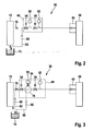
- FIG. 2 The representation according to FIG. 2 It can be seen that fuel is supplied from a low-pressure circuit 72 via a throttle point 76 of the metering unit 48.
- the low-pressure circuit 72 is over in the illustration according to FIG. 2 only schematically indicated line with a sump 74 in conjunction.
- the throttle point 76 which is also referred to as a supply throttle, the fuel flows to the metering unit 48, which in the illustration in FIG FIG. 2 is indicated by the rectangular dashed frame.
- the housing in which the metering unit 48 is housed is in FIG FIG. 2 not shown in detail.
- the shut-off valve 54 downstream of the restrictor 76 interrupts the inflow of fuel to the metering unit 48.
- the fuel flows in via for example as a check valve trained spill valve 80 via a return 82 to the sump 74 back.
- the metering unit 48 as shown in FIG. 2 a first pressure sensor 50, with which the required dosage amount to be metered is calculated. This is made available via the metering valve 56 and conveyed by this to the injection valve 40.
- This is preferably a spring-loaded injection valve, which opens when a certain opening pressure is exceeded, so that fuel can be injected into the exhaust pipe 38.
- the metering unit 48 further comprises a further, the metering valve 56 downstream pressure sensor 52.
- This downstream arranged second pressure sensor 52 serves to detect a leakage in the line which extends to the injection valve 40, and measures the pressure of the fuel at the exit from the metering unit 48th ,
- FIG. 3 shows the metering unit 48 proposed according to the invention.
- Analogous to the illustration according to FIG. 2 is the metering unit 48 as shown in FIG. 3
- Fuel from a low pressure circuit 72 supplied.
- the low pressure circuit 72 the fuel from a reservoir 74 is supplied.
- the closing valve 54 is closed, ie during regeneration pauses of the diesel particulate filter 44, the return 82 branches off to the collecting container 74 upstream of an inlet throttle 76; in this case, no fuel passes from the low-pressure circuit 72 via the inlet throttle 76 to the metering unit 48
- FIG. 3 It can be seen that the metering unit 48 has a connection between the closing valve 54 and the metering valve 56.
- a second overflow valve 80 and a parallel return 88 to the collecting container 74 is connected.
- the parallel return 88 is connected between the closing valve 54 and the metering valve 56 and / or a pressure damper 78 for receiving an additional volume of fuel and communicates with the reservoir 74 in connection.
- the metering unit 48 is constructed so that the connection of the second parallel return 88 to the collecting tank 74 between the closing valve 54 and the metering valve 56 is located.
- the pressure damper 78 is assigned via a damper throttle 84, the first pressure sensor 50.
- the second pressure sensor 52 is located at the output of the metering unit 48, the metering valve 56 downstream.
- Pressure sensor 52 a leakage in the line, which extends to the injection valve 40, detected.
- the injection valve 40 which may be executed in the simplest case as a check valve, fuel is introduced into the exhaust pipe 38 and the exhaust gas flowing there.
- the injection valve 40 formed in the simplest case as a check valve opens as soon as a certain opening pressure in the supply line, i. after the metering unit 48 is reached. This opening pressure is continuously measured via the second pressure sensor 52 included in the metering unit 48.
- the second overflow valve 80 which is contained in the parallel return 88 to the collecting container 74, may be an external component which is provided as a separate component in the parallel return 88 or on the housing of the metering unit 48, not shown. In addition, the second overflow valve 80 may also be integrated into the metering unit 48. Depending on the purpose and vehicle applications, the opening pressure can be adjusted and the flow of the fuel through the second overflow valve 80 to the reservoir 54 can be influenced.
- the largest possible pressure damper 78 is provided within the metering unit 48. Between this and the first pressure sensor 50, a further damper throttle 84 may be provided. By suitable adjustment of the throttle cross-section of the damper throttle 84 in conjunction with the defined opening time of the second overflow valve 80, which is received in the parallel return line 88, the desired operating pressure range can be set in the metering unit 48 and also maintained for operation.
- damping measures can also be undertaken outside the metering unit 48.
- the pressure level may be reduced to accommodate any specifications of the closure valve 54.
- pressure oscillations that occur in the low-pressure circuit 72 can be reduced before the metering unit 48 by providing a damping volume in the area of the inlet throttle 76 in front of the metering unit 48.
- an elastic hose or the like may be used, which extends between the low-pressure circuit 72 and the metering unit 48.
- the connection of the first pressure sensor 50 behind the closing valve 54 takes place for example via a bore provided in the valve housing. Due to the direct connection of the first pressure sensor 50, pressure fluctuations and cavitation events that occur downstream of the closing valve 54 and thus cause supply pressure fluctuations can be compensated. To avoid pressure peaks before the first pressure sensor 50 or To minimize, the following measures can be taken: simple connection of the first pressure sensor 50 to the damper throttle 84, as in FIG. 3 shown. Furthermore, by representing a generously dimensioned fuel volume, ie the pressure damper 78, with the aid of the already mentioned compensation chamber or the extension part, an attenuation of pressure fluctuations can be achieved.
- the metering of the amount of fuel ultimately required for injection into the exhaust gas line 38 takes place with the aid of the metering valve 56, which is followed by the second pressure sensor 52 for measuring the pressure level.
- the closing valve 54 interrupts the inflow of fuel to the metering valve 56 in the regeneration pauses.
- the fuel flows back into the collecting container 74 via the first overflow valve 80, which is arranged upstream of the inlet throttle 76. If the closing valve 54 is opened, the fuel can reach the metering valve 56 after passage of the pressure damper 78.
- the first pressure sensor 50 is arranged for optimal coordination or calculation of the amount of fuel to be metered into the exhaust gas flow. This serves to calculate the required dosing quantity. This metered amount is made available via the metering valve 56 and conveyed to the injection valve 40.
- injection valve 40 may be a passively opening valve, for example a check valve which opens when a specific opening pressure is reached and injects fuel, in particular diesel fuel, into exhaust pipe 38 of exhaust tract 36.
- the injection valve 40 for example, in a in the illustration according to FIG. 3 Screwed not shown heat sink, which is supplied for example directly via the cooling water circuit of the internal combustion engine 10.
- the cooling of the injection valve 40 can also be made possible by means of a fuel flow, not shown in the drawing, which is guided past the injection valve 40.
- the basic connection of the second pressure sensor 52 is in the embodiments according to the representations in the FIGS. 2 and 3 identical.
- an additional serving as a pressure damper volume 78 available is provided downstream of the closing valve 54 and downstream of the first pressure sensor 50 in the metering unit 48.
- This may be provided, for example, as a cross-sectional widening in the direction of the metering unit 48, such as by a bore extension being represented.
- the provision of this additional volume 78> 2 cm 3 or between 2 cm 3 and 20 cm 3 , in particular between 2 cm 3 and 10 cm 3 serves as a damping volume within the metering unit 48.
- the metering unit 48 is, as already mentioned, as shown in FIG. 3 , connected to the low pressure circuit 72.
- the metering line leaves the metering unit 48 downstream of the second pressure sensor 52 and extends to the injection valve 40.
- This can be cooled in a cost effective manner, since the exhaust gas temperature when flowing through the oxidation catalyst to about 600 ° C increases.
- cooling device With the aid of a in the illustration according to FIG. 3 not shown cooling device, a rapid aging of the fuel can be avoided.
- a fuel return can be connected to the metering, which in turn is connected via a controllable or adjustable pressure valve to the collecting container 74.
Landscapes
- Engineering & Computer Science (AREA)
- Chemical & Material Sciences (AREA)
- Chemical Kinetics & Catalysis (AREA)
- Mechanical Engineering (AREA)
- General Engineering & Computer Science (AREA)
- Combustion & Propulsion (AREA)
- Toxicology (AREA)
- Health & Medical Sciences (AREA)
- Materials Engineering (AREA)
- Exhaust Gas After Treatment (AREA)
- Processes For Solid Components From Exhaust (AREA)
- Electrical Control Of Air Or Fuel Supplied To Internal-Combustion Engine (AREA)
- Fuel-Injection Apparatus (AREA)
Claims (14)
- Dispositif de dosage de carburant en amont d'un catalyseur d'oxydation (42) dans le système de gaz d'échappement (36) d'un moteur à combustion interne (10), dans lequel, en aval d'un dispositif d'alimentation (72) de carburant, une soupape (54) ainsi qu'une buse d'injection (40) sont intégrées dans une conduite d'une unité de dosage (48), de laquelle part un retour (82) avec une première soupape de débordement (80), caractérisé en ce qu'en aval de la soupape (54) est disposé un retour supplémentaire (88) avec une soupape (90) influençant un niveau de pression moyen de l'unité de dosage (48).
- Dispositif de dosage selon la revendication 1, caractérisé en ce qu'en aval de la soupape (54) est disposée une soupape de dosage (56).
- Dispositif de dosage selon la revendication 2, caractérisé en ce que le retour supplémentaire (88) est disposé entre la soupape (54) et la soupape de dosage (56).
- Dispositif de dosage selon l'une quelconque des revendications précédentes, caractérisé en ce qu'en aval du dispositif d'alimentation (72) de carburant, en particulier de carburant diesel, est monté un point d'étranglement (76, 86) en amont de l'unité de dosage (48).
- Dispositif de dosage selon l'une quelconque des revendications précédentes, caractérisé en ce qu'un dispositif (78, 84) d'amortissement des variations de pression est intégré dans le système de conduites de l'unité de dosage (48).
- Dispositif de dosage selon la revendication 5, caractérisé en ce que l'unité de dosage (48) est raccordée par le biais du retour (82) présentant une première soupape de débordement (80) à un récipient collecteur (74) dans le véhicule automobile, et en aval après le point de raccordement du retour (82), l'unité de dosage (48) et/ou la soupape de fermeture (54) est pourvue du dispositif (78, 84) d'amortissement des variations de pression.
- Dispositif de dosage selon la revendication 5, caractérisé en ce que le dispositif d'amortissement (78, 84) des variations de pression comprend au moins un organe d'étranglement d'amortissement (84) et/ou une chambre associée à l'unité de dosage (48) ou un élargissement dans le système de conduites de l'unité de dosage (48).
- Dispositif de dosage selon les revendications 2, 4 et 7, caractérisé en ce que l'organe d'étranglement d'alimentation (86) est prévu en aval après le point de raccordement du retour (82), avant la soupape de fermeture (54), et l'organe d'étranglement d'amortissement (84) est prévu dans l'unité de dosage (48) entre la soupape de fermeture (54) et la soupape de dosage (56).
- Dispositif de dosage selon les revendications 2 et 5, caractérisé en ce que le dispositif (78, 84) d'amortissement des variations de pression est intégré entre la soupape de fermeture (54) et la soupape de dosage (56) dans l'unité de dosage (48).
- Dispositif de dosage selon la revendication 7, caractérisé en ce que le dispositif (78, 84) d'amortissement des variations de pression sous forme de récipient ou de partie d'élargissement pour recevoir un volume de carburant supplémentaire fait partie d'un bloc-soupape ou fait partie du système de conduites de l'unité de dosage (48).
- Dispositif de dosage selon les revendications 2 et 5, caractérisé en ce que dans l'unité de dosage (48) après la soupape de fermeture (54) et avant la soupape de dosage (56), est prévu au moins un premier capteur de pression (50) qui est en liaison fonctionnelle avec le dispositif (78, 84) d'amortissement des variations de pression.
- Dispositif de dosage selon l'une quelconque des revendications précédentes, caractérisé en ce qu'entre la soupape de fermeture (54) et la soupape de dosage (56), au moins un point d'étranglement (84) est connecté au premier capteur de pression (50), lequel point d'étranglement est en liaison fonctionnelle avec le dispositif (78) d'amortissement des variations de pression.
- Dispositif de dosage selon l'une quelconque des revendications précédentes, caractérisé en ce qu'entre la soupape de fermeture (54) et la soupape de dosage (56) ou un amortisseur de pression (78) s'étend le retour parallèle (88) avec une deuxième soupape de débordement (90).
- Dispositif de dosage selon l'une quelconque des revendications précédentes, caractérisé en ce que la buse d'injection (40) est réalisée sous forme de soupape d'injection.
Applications Claiming Priority (2)
| Application Number | Priority Date | Filing Date | Title |
|---|---|---|---|
| DE102008040463A DE102008040463A1 (de) | 2008-07-16 | 2008-07-16 | Vorrichtung zur Eindosierung von Kraftstoff |
| PCT/EP2009/055972 WO2010006829A1 (fr) | 2008-07-16 | 2009-05-18 | Dispositif de dosage de carburant |
Publications (2)
| Publication Number | Publication Date |
|---|---|
| EP2304200A1 EP2304200A1 (fr) | 2011-04-06 |
| EP2304200B1 true EP2304200B1 (fr) | 2013-09-25 |
Family
ID=41008904
Family Applications (1)
| Application Number | Title | Priority Date | Filing Date |
|---|---|---|---|
| EP09779499.4A Active EP2304200B1 (fr) | 2008-07-16 | 2009-05-18 | Dispositif de dosage de carburant |
Country Status (7)
| Country | Link |
|---|---|
| US (1) | US8528324B2 (fr) |
| EP (1) | EP2304200B1 (fr) |
| JP (1) | JP5312583B2 (fr) |
| CN (1) | CN102099554A (fr) |
| DE (1) | DE102008040463A1 (fr) |
| RU (1) | RU2490483C2 (fr) |
| WO (1) | WO2010006829A1 (fr) |
Families Citing this family (11)
| Publication number | Priority date | Publication date | Assignee | Title |
|---|---|---|---|---|
| FR2839446B1 (fr) | 2002-05-13 | 2006-06-30 | Oreal | Composes diazirine-actifs photo-activables, compositions les contenant et leurs utilisations |
| DE102011081580A1 (de) * | 2011-03-04 | 2012-09-06 | Robert Bosch Gmbh | Abgasnachbehandlungssystem einer Brennkraftmaschine und Verfahren zur Eindosierung einer Flüssigkeit in den Abgaskanal der Brennkraftmaschine |
| FR2973832B1 (fr) * | 2011-04-08 | 2015-05-29 | Peugeot Citroen Automobiles Sa | Dispositif de dosage d'injection dans un systeme de reduction catalytique selective |
| DE102011081628A1 (de) * | 2011-08-26 | 2013-02-28 | Robert Bosch Gmbh | Dosiersystem für ein flüssiges Reduktionsmittel |
| DE102012222040A1 (de) | 2012-12-03 | 2014-06-05 | Robert Bosch Gmbh | Eindosierungsvorrichtung |
| DE102013220799B4 (de) * | 2013-10-15 | 2018-11-29 | Continental Automotive Gmbh | Dosieranlage zur Zuführung von Substanzen in Gasströme |
| JP2016176365A (ja) * | 2015-03-19 | 2016-10-06 | いすゞ自動車株式会社 | 内燃機関及び捕集装置の強制再生方法 |
| JP6489642B2 (ja) * | 2015-04-27 | 2019-03-27 | 日野自動車株式会社 | 排気浄化装置 |
| CN106593604B (zh) * | 2016-12-26 | 2022-05-24 | 南岳电控(衡阳)工业技术股份有限公司 | 一种柴油车hc喷射装置 |
| CN107060954B (zh) * | 2017-03-22 | 2023-04-07 | 中国第一汽车股份有限公司 | 用于净化排气碳烟颗粒的喷射系统及控制方法 |
| WO2020214920A1 (fr) | 2019-04-18 | 2020-10-22 | Cummins Inc. | Appareil, système et procédé de gestion thermique par déploiement de l'alimentation en carburant d'un moteur à la demande |
Family Cites Families (16)
| Publication number | Priority date | Publication date | Assignee | Title |
|---|---|---|---|---|
| JPH0631153Y2 (ja) * | 1987-05-26 | 1994-08-22 | ダイハツ工業株式会社 | 内燃機関の吸気圧検出装置 |
| DE19946900A1 (de) * | 1999-06-22 | 2000-12-28 | Bosch Gmbh Robert | Vorrichtung zur Dosierung eines Reduktionsmittels |
| JP4306101B2 (ja) * | 2000-07-24 | 2009-07-29 | トヨタ自動車株式会社 | エンジンの燃料供給装置 |
| JP2002242780A (ja) * | 2001-02-16 | 2002-08-28 | Toyota Motor Corp | 内燃機関の燃料供給装置 |
| JP2003344713A (ja) | 2002-05-29 | 2003-12-03 | Kyocera Corp | 光素子モジュール及びその製造方法 |
| DE10324482B4 (de) * | 2003-05-30 | 2014-08-21 | Robert Bosch Gmbh | Vorrichtung zur Dosierung eines Reduktionsmittels zum Abgas eines Verbrennungsmotors |
| US7594393B2 (en) | 2004-09-07 | 2009-09-29 | Robert Bosch Gmbh | Apparatus for introducing a reducing agent into the exhaust of an internal combustion engine |
| AT500849B8 (de) * | 2004-11-15 | 2007-02-15 | Pankl Emission Control Systems | Harnstoffdosiervorrichtung |
| DE102005034704A1 (de) | 2005-07-26 | 2007-02-01 | Robert Bosch Gmbh | Vorrichtung und Verfahren zur Regeneration eines Partikelfilters |
| DE102005046070A1 (de) * | 2005-09-27 | 2007-03-29 | Daimlerchrysler Ag | Vorrichtung zum Dosieren von Kraftstoff in ein Abgassystem einer Brennkraftmaschine |
| DE102006009099A1 (de) * | 2006-02-28 | 2007-08-30 | Daimlerchrysler Ag | Einspritzsystem mit einer Vorrichtung zum Dosieren von Kraftstoff in ein Abgassystem einer Brennkraftmaschine und einem Verfahren hierzu |
| DE102006032155A1 (de) | 2006-07-12 | 2008-01-24 | Daimler Ag | Brennkraftmaschine eines Kraftfahrzeugs |
| EP2047076A1 (fr) | 2006-07-13 | 2009-04-15 | Inergy Automotive Systems Research (Société A.) | Système et procédé permettant de stocker un additif et de l'injecter dans les gaz d'échappement d'un moteur |
| JP4616817B2 (ja) * | 2006-11-10 | 2011-01-19 | 三菱重工業株式会社 | エンジンの蓄圧式燃料噴射装置 |
| DE102006062491A1 (de) * | 2006-12-28 | 2008-07-03 | Robert Bosch Gmbh | Vorrichtung zur Dosierung von Kraftstoff zum Abgassystem eines Verbrennungsmotors |
| US8116972B2 (en) * | 2008-02-08 | 2012-02-14 | Ford Global Technologies, Llc | System and method for determining a vehicle refueling strategy |
-
2008
- 2008-07-16 DE DE102008040463A patent/DE102008040463A1/de not_active Withdrawn
-
2009
- 2009-05-18 US US13/054,320 patent/US8528324B2/en not_active Expired - Fee Related
- 2009-05-18 RU RU2011105053/06A patent/RU2490483C2/ru not_active IP Right Cessation
- 2009-05-18 JP JP2011517827A patent/JP5312583B2/ja not_active Expired - Fee Related
- 2009-05-18 WO PCT/EP2009/055972 patent/WO2010006829A1/fr not_active Ceased
- 2009-05-18 EP EP09779499.4A patent/EP2304200B1/fr active Active
- 2009-05-18 CN CN2009801279419A patent/CN102099554A/zh active Pending
Also Published As
| Publication number | Publication date |
|---|---|
| RU2490483C2 (ru) | 2013-08-20 |
| RU2011105053A (ru) | 2012-08-27 |
| WO2010006829A1 (fr) | 2010-01-21 |
| JP5312583B2 (ja) | 2013-10-09 |
| EP2304200A1 (fr) | 2011-04-06 |
| JP2011528080A (ja) | 2011-11-10 |
| US20110138792A1 (en) | 2011-06-16 |
| CN102099554A (zh) | 2011-06-15 |
| DE102008040463A1 (de) | 2010-01-21 |
| US8528324B2 (en) | 2013-09-10 |
Similar Documents
| Publication | Publication Date | Title |
|---|---|---|
| EP2304200B1 (fr) | Dispositif de dosage de carburant | |
| EP1989410B1 (fr) | Systeme d'injection dote d'un dispositif de dosage de carburant dans un systeme de gaz d'echappement d'un moteur a combustion interne et procede correspondant | |
| DE102009026754B4 (de) | Abgasreinigungsvorrichtung und Verfahren zum Reinigen von Abgas | |
| DE19947198B4 (de) | Vorrichtung zum Nachbehandeln von Abgasen einer Brennkraftmaschine | |
| EP2789839A2 (fr) | Système et procédé d'injection d'eau pour un moteur à combustion interne | |
| DE4041628A1 (de) | Gemischverdichtende brennkraftmaschine mit sekundaerlufteinblasung und mit luftmassenmessung im saugrohr | |
| DE102012113108A1 (de) | Fahrzeug mit einem system und einem verfahren zum diagnostizieren von sekundärlufteinblas-vorrichtung | |
| EP2647814B1 (fr) | Procédé et dispositif de commande du fonctionnement du frein-moteur sur des moteurs à combustion interne | |
| EP3346120B1 (fr) | Dispositif d'injection d'eau d'un moteur à combustion interne et procédé de fonctionnement d'un tel dispositif d'injection d'eau | |
| DE102011003912A1 (de) | Vorrichtung und Verfahren zur Eindosierung einer Flüssigkeit in den Abgasstrang einer Brennkraftmaschine | |
| WO2009024447A1 (fr) | Système d'injection pour un moteur à combustion interne | |
| EP1582709B1 (fr) | Méthode de régénération d'un filtre à particule ainsi qu'un système d'échappement avec un filtre à particule | |
| WO2010052120A1 (fr) | Système d'injection pour moteur à combustion interne | |
| EP2337933A1 (fr) | Dispositif de dosage de carburant | |
| DE102005061876A1 (de) | Verfahren und Vorrichtung zur Steuerung eines Abgasnachbehandlungssystems | |
| WO2009010569A1 (fr) | Dispositif et procédé pour doser un agent de réduction dans un circuit d'échappement d'un véhicule | |
| WO2010072443A1 (fr) | Dispositif pour le dosage de carburant | |
| DE102010035364B4 (de) | Vorrichtung zum Betreiben einer Brennkraftmaschine | |
| DE102017205777A1 (de) | Verfahren zur Überwachung des Volumenstroms eines Dosierventils eines fluidischen Dosiersystems einer Brennkraftmaschine insbesondere eines Kraftfahrzeugs | |
| WO2011113659A1 (fr) | Procédé et dispositif d'évaluation d'un injecteur | |
| DE102013108225A1 (de) | Abgasrückführungs-Steuervorrichtung und Verfahren für eine Brennkraftmaschine | |
| DE10233945A1 (de) | Verfahren zur Reinigung eines Partikelfilters | |
| DE102018216767A1 (de) | Maschinensystem und verfahren zum steuern von diesem | |
| EP3337962B1 (fr) | Dispositif d'alimentation en carburant pour injection moteur et post-traitement des gaz d'échappement | |
| DE102013224414A1 (de) | Verfahren zum Betreiben eines Fluidfördersystems |
Legal Events
| Date | Code | Title | Description |
|---|---|---|---|
| PUAI | Public reference made under article 153(3) epc to a published international application that has entered the european phase |
Free format text: ORIGINAL CODE: 0009012 |
|
| 17P | Request for examination filed |
Effective date: 20110216 |
|
| AK | Designated contracting states |
Kind code of ref document: A1 Designated state(s): AT BE BG CH CY CZ DE DK EE ES FI FR GB GR HR HU IE IS IT LI LT LU LV MC MK MT NL NO PL PT RO SE SI SK TR |
|
| AX | Request for extension of the european patent |
Extension state: AL BA RS |
|
| DAX | Request for extension of the european patent (deleted) | ||
| GRAP | Despatch of communication of intention to grant a patent |
Free format text: ORIGINAL CODE: EPIDOSNIGR1 |
|
| INTG | Intention to grant announced |
Effective date: 20130625 |
|
| GRAS | Grant fee paid |
Free format text: ORIGINAL CODE: EPIDOSNIGR3 |
|
| GRAA | (expected) grant |
Free format text: ORIGINAL CODE: 0009210 |
|
| AK | Designated contracting states |
Kind code of ref document: B1 Designated state(s): AT BE BG CH CY CZ DE DK EE ES FI FR GB GR HR HU IE IS IT LI LT LU LV MC MK MT NL NO PL PT RO SE SI SK TR |
|
| REG | Reference to a national code |
Ref country code: GB Ref legal event code: FG4D Free format text: NOT ENGLISH |
|
| REG | Reference to a national code |
Ref country code: CH Ref legal event code: EP |
|
| REG | Reference to a national code |
Ref country code: AT Ref legal event code: REF Ref document number: 633802 Country of ref document: AT Kind code of ref document: T Effective date: 20131015 |
|
| REG | Reference to a national code |
Ref country code: IE Ref legal event code: FG4D Free format text: LANGUAGE OF EP DOCUMENT: GERMAN |
|
| REG | Reference to a national code |
Ref country code: DE Ref legal event code: R096 Ref document number: 502009008071 Country of ref document: DE Effective date: 20131121 |
|
| PG25 | Lapsed in a contracting state [announced via postgrant information from national office to epo] |
Ref country code: LT Free format text: LAPSE BECAUSE OF FAILURE TO SUBMIT A TRANSLATION OF THE DESCRIPTION OR TO PAY THE FEE WITHIN THE PRESCRIBED TIME-LIMIT Effective date: 20130925 Ref country code: HR Free format text: LAPSE BECAUSE OF FAILURE TO SUBMIT A TRANSLATION OF THE DESCRIPTION OR TO PAY THE FEE WITHIN THE PRESCRIBED TIME-LIMIT Effective date: 20130925 Ref country code: NO Free format text: LAPSE BECAUSE OF FAILURE TO SUBMIT A TRANSLATION OF THE DESCRIPTION OR TO PAY THE FEE WITHIN THE PRESCRIBED TIME-LIMIT Effective date: 20131225 Ref country code: SE Free format text: LAPSE BECAUSE OF FAILURE TO SUBMIT A TRANSLATION OF THE DESCRIPTION OR TO PAY THE FEE WITHIN THE PRESCRIBED TIME-LIMIT Effective date: 20130925 |
|
| REG | Reference to a national code |
Ref country code: NL Ref legal event code: VDEP Effective date: 20130925 |
|
| REG | Reference to a national code |
Ref country code: LT Ref legal event code: MG4D |
|
| PG25 | Lapsed in a contracting state [announced via postgrant information from national office to epo] |
Ref country code: GR Free format text: LAPSE BECAUSE OF FAILURE TO SUBMIT A TRANSLATION OF THE DESCRIPTION OR TO PAY THE FEE WITHIN THE PRESCRIBED TIME-LIMIT Effective date: 20131226 Ref country code: LV Free format text: LAPSE BECAUSE OF FAILURE TO SUBMIT A TRANSLATION OF THE DESCRIPTION OR TO PAY THE FEE WITHIN THE PRESCRIBED TIME-LIMIT Effective date: 20130925 Ref country code: FI Free format text: LAPSE BECAUSE OF FAILURE TO SUBMIT A TRANSLATION OF THE DESCRIPTION OR TO PAY THE FEE WITHIN THE PRESCRIBED TIME-LIMIT Effective date: 20130925 Ref country code: SI Free format text: LAPSE BECAUSE OF FAILURE TO SUBMIT A TRANSLATION OF THE DESCRIPTION OR TO PAY THE FEE WITHIN THE PRESCRIBED TIME-LIMIT Effective date: 20130925 |
|
| PG25 | Lapsed in a contracting state [announced via postgrant information from national office to epo] |
Ref country code: IS Free format text: LAPSE BECAUSE OF FAILURE TO SUBMIT A TRANSLATION OF THE DESCRIPTION OR TO PAY THE FEE WITHIN THE PRESCRIBED TIME-LIMIT Effective date: 20140125 Ref country code: SK Free format text: LAPSE BECAUSE OF FAILURE TO SUBMIT A TRANSLATION OF THE DESCRIPTION OR TO PAY THE FEE WITHIN THE PRESCRIBED TIME-LIMIT Effective date: 20130925 Ref country code: RO Free format text: LAPSE BECAUSE OF FAILURE TO SUBMIT A TRANSLATION OF THE DESCRIPTION OR TO PAY THE FEE WITHIN THE PRESCRIBED TIME-LIMIT Effective date: 20130925 Ref country code: CZ Free format text: LAPSE BECAUSE OF FAILURE TO SUBMIT A TRANSLATION OF THE DESCRIPTION OR TO PAY THE FEE WITHIN THE PRESCRIBED TIME-LIMIT Effective date: 20130925 Ref country code: EE Free format text: LAPSE BECAUSE OF FAILURE TO SUBMIT A TRANSLATION OF THE DESCRIPTION OR TO PAY THE FEE WITHIN THE PRESCRIBED TIME-LIMIT Effective date: 20130925 Ref country code: NL Free format text: LAPSE BECAUSE OF FAILURE TO SUBMIT A TRANSLATION OF THE DESCRIPTION OR TO PAY THE FEE WITHIN THE PRESCRIBED TIME-LIMIT Effective date: 20130925 |
|
| PG25 | Lapsed in a contracting state [announced via postgrant information from national office to epo] |
Ref country code: CY Free format text: LAPSE BECAUSE OF FAILURE TO SUBMIT A TRANSLATION OF THE DESCRIPTION OR TO PAY THE FEE WITHIN THE PRESCRIBED TIME-LIMIT Effective date: 20130925 Ref country code: PL Free format text: LAPSE BECAUSE OF FAILURE TO SUBMIT A TRANSLATION OF THE DESCRIPTION OR TO PAY THE FEE WITHIN THE PRESCRIBED TIME-LIMIT Effective date: 20130925 Ref country code: ES Free format text: LAPSE BECAUSE OF FAILURE TO SUBMIT A TRANSLATION OF THE DESCRIPTION OR TO PAY THE FEE WITHIN THE PRESCRIBED TIME-LIMIT Effective date: 20130925 |
|
| REG | Reference to a national code |
Ref country code: DE Ref legal event code: R097 Ref document number: 502009008071 Country of ref document: DE |
|
| PG25 | Lapsed in a contracting state [announced via postgrant information from national office to epo] |
Ref country code: PT Free format text: LAPSE BECAUSE OF FAILURE TO SUBMIT A TRANSLATION OF THE DESCRIPTION OR TO PAY THE FEE WITHIN THE PRESCRIBED TIME-LIMIT Effective date: 20140127 |
|
| PLBE | No opposition filed within time limit |
Free format text: ORIGINAL CODE: 0009261 |
|
| STAA | Information on the status of an ep patent application or granted ep patent |
Free format text: STATUS: NO OPPOSITION FILED WITHIN TIME LIMIT |
|
| PG25 | Lapsed in a contracting state [announced via postgrant information from national office to epo] |
Ref country code: IT Free format text: LAPSE BECAUSE OF FAILURE TO SUBMIT A TRANSLATION OF THE DESCRIPTION OR TO PAY THE FEE WITHIN THE PRESCRIBED TIME-LIMIT Effective date: 20130925 |
|
| 26N | No opposition filed |
Effective date: 20140626 |
|
| PG25 | Lapsed in a contracting state [announced via postgrant information from national office to epo] |
Ref country code: DK Free format text: LAPSE BECAUSE OF FAILURE TO SUBMIT A TRANSLATION OF THE DESCRIPTION OR TO PAY THE FEE WITHIN THE PRESCRIBED TIME-LIMIT Effective date: 20130925 |
|
| REG | Reference to a national code |
Ref country code: DE Ref legal event code: R097 Ref document number: 502009008071 Country of ref document: DE Effective date: 20140626 |
|
| PG25 | Lapsed in a contracting state [announced via postgrant information from national office to epo] |
Ref country code: LU Free format text: LAPSE BECAUSE OF FAILURE TO SUBMIT A TRANSLATION OF THE DESCRIPTION OR TO PAY THE FEE WITHIN THE PRESCRIBED TIME-LIMIT Effective date: 20140518 |
|
| REG | Reference to a national code |
Ref country code: CH Ref legal event code: PL |
|
| GBPC | Gb: european patent ceased through non-payment of renewal fee |
Effective date: 20140518 |
|
| PG25 | Lapsed in a contracting state [announced via postgrant information from national office to epo] |
Ref country code: MC Free format text: LAPSE BECAUSE OF FAILURE TO SUBMIT A TRANSLATION OF THE DESCRIPTION OR TO PAY THE FEE WITHIN THE PRESCRIBED TIME-LIMIT Effective date: 20130925 Ref country code: CH Free format text: LAPSE BECAUSE OF NON-PAYMENT OF DUE FEES Effective date: 20140531 Ref country code: LI Free format text: LAPSE BECAUSE OF NON-PAYMENT OF DUE FEES Effective date: 20140531 |
|
| REG | Reference to a national code |
Ref country code: IE Ref legal event code: MM4A |
|
| PG25 | Lapsed in a contracting state [announced via postgrant information from national office to epo] |
Ref country code: IE Free format text: LAPSE BECAUSE OF NON-PAYMENT OF DUE FEES Effective date: 20140518 |
|
| PG25 | Lapsed in a contracting state [announced via postgrant information from national office to epo] |
Ref country code: GB Free format text: LAPSE BECAUSE OF NON-PAYMENT OF DUE FEES Effective date: 20140518 |
|
| REG | Reference to a national code |
Ref country code: AT Ref legal event code: MM01 Ref document number: 633802 Country of ref document: AT Kind code of ref document: T Effective date: 20140518 |
|
| PG25 | Lapsed in a contracting state [announced via postgrant information from national office to epo] |
Ref country code: AT Free format text: LAPSE BECAUSE OF NON-PAYMENT OF DUE FEES Effective date: 20140518 |
|
| PG25 | Lapsed in a contracting state [announced via postgrant information from national office to epo] |
Ref country code: MT Free format text: LAPSE BECAUSE OF FAILURE TO SUBMIT A TRANSLATION OF THE DESCRIPTION OR TO PAY THE FEE WITHIN THE PRESCRIBED TIME-LIMIT Effective date: 20130925 |
|
| REG | Reference to a national code |
Ref country code: FR Ref legal event code: PLFP Year of fee payment: 8 |
|
| PG25 | Lapsed in a contracting state [announced via postgrant information from national office to epo] |
Ref country code: BG Free format text: LAPSE BECAUSE OF FAILURE TO SUBMIT A TRANSLATION OF THE DESCRIPTION OR TO PAY THE FEE WITHIN THE PRESCRIBED TIME-LIMIT Effective date: 20130925 |
|
| PG25 | Lapsed in a contracting state [announced via postgrant information from national office to epo] |
Ref country code: TR Free format text: LAPSE BECAUSE OF FAILURE TO SUBMIT A TRANSLATION OF THE DESCRIPTION OR TO PAY THE FEE WITHIN THE PRESCRIBED TIME-LIMIT Effective date: 20130925 Ref country code: HU Free format text: LAPSE BECAUSE OF FAILURE TO SUBMIT A TRANSLATION OF THE DESCRIPTION OR TO PAY THE FEE WITHIN THE PRESCRIBED TIME-LIMIT; INVALID AB INITIO Effective date: 20090518 Ref country code: BE Free format text: LAPSE BECAUSE OF FAILURE TO SUBMIT A TRANSLATION OF THE DESCRIPTION OR TO PAY THE FEE WITHIN THE PRESCRIBED TIME-LIMIT Effective date: 20140531 |
|
| REG | Reference to a national code |
Ref country code: FR Ref legal event code: PLFP Year of fee payment: 9 |
|
| REG | Reference to a national code |
Ref country code: FR Ref legal event code: PLFP Year of fee payment: 10 |
|
| PG25 | Lapsed in a contracting state [announced via postgrant information from national office to epo] |
Ref country code: MK Free format text: LAPSE BECAUSE OF FAILURE TO SUBMIT A TRANSLATION OF THE DESCRIPTION OR TO PAY THE FEE WITHIN THE PRESCRIBED TIME-LIMIT Effective date: 20130925 |
|
| PGFP | Annual fee paid to national office [announced via postgrant information from national office to epo] |
Ref country code: FR Payment date: 20190521 Year of fee payment: 11 |
|
| PG25 | Lapsed in a contracting state [announced via postgrant information from national office to epo] |
Ref country code: FR Free format text: LAPSE BECAUSE OF NON-PAYMENT OF DUE FEES Effective date: 20200531 |
|
| PGFP | Annual fee paid to national office [announced via postgrant information from national office to epo] |
Ref country code: DE Payment date: 20250716 Year of fee payment: 17 |