EP2304225B1 - Aube pour turbine à eau - Google Patents
Aube pour turbine à eau Download PDFInfo
- Publication number
- EP2304225B1 EP2304225B1 EP09732944.5A EP09732944A EP2304225B1 EP 2304225 B1 EP2304225 B1 EP 2304225B1 EP 09732944 A EP09732944 A EP 09732944A EP 2304225 B1 EP2304225 B1 EP 2304225B1
- Authority
- EP
- European Patent Office
- Prior art keywords
- blade
- central axis
- rotor
- power generator
- turbine
- Prior art date
- Legal status (The legal status is an assumption and is not a legal conclusion. Google has not performed a legal analysis and makes no representation as to the accuracy of the status listed.)
- Not-in-force
Links
- XLYOFNOQVPJJNP-UHFFFAOYSA-N water Substances O XLYOFNOQVPJJNP-UHFFFAOYSA-N 0.000 title claims description 35
- 229920002430 Fibre-reinforced plastic Polymers 0.000 claims description 9
- 239000011151 fibre-reinforced plastic Substances 0.000 claims description 9
- 230000025508 response to water Effects 0.000 claims 1
- 239000012530 fluid Substances 0.000 description 12
- 239000000463 material Substances 0.000 description 10
- 239000007788 liquid Substances 0.000 description 7
- 238000000034 method Methods 0.000 description 5
- 229910000831 Steel Inorganic materials 0.000 description 4
- 238000013461 design Methods 0.000 description 4
- 239000004519 grease Substances 0.000 description 4
- 238000010248 power generation Methods 0.000 description 4
- 239000010959 steel Substances 0.000 description 4
- 230000004907 flux Effects 0.000 description 3
- 229910021652 non-ferrous alloy Inorganic materials 0.000 description 3
- OKTJSMMVPCPJKN-UHFFFAOYSA-N Carbon Chemical compound [C] OKTJSMMVPCPJKN-UHFFFAOYSA-N 0.000 description 2
- 229910052799 carbon Inorganic materials 0.000 description 2
- 239000002131 composite material Substances 0.000 description 2
- 150000001875 compounds Chemical class 0.000 description 2
- 230000005611 electricity Effects 0.000 description 2
- 230000006698 induction Effects 0.000 description 2
- 230000007246 mechanism Effects 0.000 description 2
- 230000008569 process Effects 0.000 description 2
- 230000001681 protective effect Effects 0.000 description 2
- 230000004044 response Effects 0.000 description 2
- 239000013535 sea water Substances 0.000 description 2
- 238000012360 testing method Methods 0.000 description 2
- 238000012546 transfer Methods 0.000 description 2
- 238000011144 upstream manufacturing Methods 0.000 description 2
- UJCHIZDEQZMODR-BYPYZUCNSA-N (2r)-2-acetamido-3-sulfanylpropanamide Chemical compound CC(=O)N[C@@H](CS)C(N)=O UJCHIZDEQZMODR-BYPYZUCNSA-N 0.000 description 1
- 229910000975 Carbon steel Inorganic materials 0.000 description 1
- 241000238586 Cirripedia Species 0.000 description 1
- 241001669680 Dormitator maculatus Species 0.000 description 1
- 238000010521 absorption reaction Methods 0.000 description 1
- 230000004913 activation Effects 0.000 description 1
- 239000000853 adhesive Substances 0.000 description 1
- 230000001070 adhesive effect Effects 0.000 description 1
- 239000002390 adhesive tape Substances 0.000 description 1
- 230000003373 anti-fouling effect Effects 0.000 description 1
- LSWZMKLTBNIIHY-UHFFFAOYSA-N barium(2+);oxido-(oxido(dioxo)chromio)oxy-dioxochromium Chemical compound [Ba+2].[O-][Cr](=O)(=O)O[Cr]([O-])(=O)=O LSWZMKLTBNIIHY-UHFFFAOYSA-N 0.000 description 1
- 238000005452 bending Methods 0.000 description 1
- 230000008901 benefit Effects 0.000 description 1
- 239000010962 carbon steel Substances 0.000 description 1
- 230000007797 corrosion Effects 0.000 description 1
- 238000005260 corrosion Methods 0.000 description 1
- 238000005516 engineering process Methods 0.000 description 1
- 230000007717 exclusion Effects 0.000 description 1
- 239000000835 fiber Substances 0.000 description 1
- 238000007667 floating Methods 0.000 description 1
- 239000011521 glass Substances 0.000 description 1
- 239000003292 glue Substances 0.000 description 1
- 230000005484 gravity Effects 0.000 description 1
- 239000010720 hydraulic oil Substances 0.000 description 1
- 238000002955 isolation Methods 0.000 description 1
- 238000011068 loading method Methods 0.000 description 1
- 229910052751 metal Inorganic materials 0.000 description 1
- 239000002184 metal Substances 0.000 description 1
- 238000012986 modification Methods 0.000 description 1
- 230000004048 modification Effects 0.000 description 1
- 230000005405 multipole Effects 0.000 description 1
- 239000003973 paint Substances 0.000 description 1
- 229920002635 polyurethane Polymers 0.000 description 1
- 239000004814 polyurethane Substances 0.000 description 1
- 230000000069 prophylactic effect Effects 0.000 description 1
- 230000009467 reduction Effects 0.000 description 1
- 230000001105 regulatory effect Effects 0.000 description 1
- 239000000565 sealant Substances 0.000 description 1
- 239000007787 solid Substances 0.000 description 1
- 239000010935 stainless steel Substances 0.000 description 1
- 229910001220 stainless steel Inorganic materials 0.000 description 1
- 239000000758 substrate Substances 0.000 description 1
Images




Classifications
-
- F—MECHANICAL ENGINEERING; LIGHTING; HEATING; WEAPONS; BLASTING
- F03—MACHINES OR ENGINES FOR LIQUIDS; WIND, SPRING, OR WEIGHT MOTORS; PRODUCING MECHANICAL POWER OR A REACTIVE PROPULSIVE THRUST, NOT OTHERWISE PROVIDED FOR
- F03B—MACHINES OR ENGINES FOR LIQUIDS
- F03B3/00—Machines or engines of reaction type; Parts or details peculiar thereto
- F03B3/12—Blades; Blade-carrying rotors
- F03B3/121—Blades, their form or construction
-
- E—FIXED CONSTRUCTIONS
- E02—HYDRAULIC ENGINEERING; FOUNDATIONS; SOIL SHIFTING
- E02B—HYDRAULIC ENGINEERING
- E02B9/00—Water-power plants; Layout, construction or equipment, methods of, or apparatus for, making same
-
- F—MECHANICAL ENGINEERING; LIGHTING; HEATING; WEAPONS; BLASTING
- F03—MACHINES OR ENGINES FOR LIQUIDS; WIND, SPRING, OR WEIGHT MOTORS; PRODUCING MECHANICAL POWER OR A REACTIVE PROPULSIVE THRUST, NOT OTHERWISE PROVIDED FOR
- F03B—MACHINES OR ENGINES FOR LIQUIDS
- F03B13/00—Adaptations of machines or engines for special use; Combinations of machines or engines with driving or driven apparatus; Power stations or aggregates
- F03B13/12—Adaptations of machines or engines for special use; Combinations of machines or engines with driving or driven apparatus; Power stations or aggregates characterised by using wave or tide energy
- F03B13/26—Adaptations of machines or engines for special use; Combinations of machines or engines with driving or driven apparatus; Power stations or aggregates characterised by using wave or tide energy using tide energy
- F03B13/264—Adaptations of machines or engines for special use; Combinations of machines or engines with driving or driven apparatus; Power stations or aggregates characterised by using wave or tide energy using tide energy using the horizontal flow of water resulting from tide movement
-
- F—MECHANICAL ENGINEERING; LIGHTING; HEATING; WEAPONS; BLASTING
- F03—MACHINES OR ENGINES FOR LIQUIDS; WIND, SPRING, OR WEIGHT MOTORS; PRODUCING MECHANICAL POWER OR A REACTIVE PROPULSIVE THRUST, NOT OTHERWISE PROVIDED FOR
- F03B—MACHINES OR ENGINES FOR LIQUIDS
- F03B17/00—Other machines or engines
- F03B17/06—Other machines or engines using liquid flow with predominantly kinetic energy conversion, e.g. of swinging-flap type, "run-of-river", "ultra-low head"
- F03B17/061—Other machines or engines using liquid flow with predominantly kinetic energy conversion, e.g. of swinging-flap type, "run-of-river", "ultra-low head" with rotation axis substantially in flow direction
-
- F—MECHANICAL ENGINEERING; LIGHTING; HEATING; WEAPONS; BLASTING
- F05—INDEXING SCHEMES RELATING TO ENGINES OR PUMPS IN VARIOUS SUBCLASSES OF CLASSES F01-F04
- F05B—INDEXING SCHEME RELATING TO WIND, SPRING, WEIGHT, INERTIA OR LIKE MOTORS, TO MACHINES OR ENGINES FOR LIQUIDS COVERED BY SUBCLASSES F03B, F03D AND F03G
- F05B2240/00—Components
- F05B2240/10—Stators
- F05B2240/13—Stators to collect or cause flow towards or away from turbines
- F05B2240/133—Stators to collect or cause flow towards or away from turbines with a convergent-divergent guiding structure, e.g. a Venturi conduit
-
- F—MECHANICAL ENGINEERING; LIGHTING; HEATING; WEAPONS; BLASTING
- F05—INDEXING SCHEMES RELATING TO ENGINES OR PUMPS IN VARIOUS SUBCLASSES OF CLASSES F01-F04
- F05B—INDEXING SCHEME RELATING TO WIND, SPRING, WEIGHT, INERTIA OR LIKE MOTORS, TO MACHINES OR ENGINES FOR LIQUIDS COVERED BY SUBCLASSES F03B, F03D AND F03G
- F05B2240/00—Components
- F05B2240/20—Rotors
-
- F—MECHANICAL ENGINEERING; LIGHTING; HEATING; WEAPONS; BLASTING
- F05—INDEXING SCHEMES RELATING TO ENGINES OR PUMPS IN VARIOUS SUBCLASSES OF CLASSES F01-F04
- F05B—INDEXING SCHEME RELATING TO WIND, SPRING, WEIGHT, INERTIA OR LIKE MOTORS, TO MACHINES OR ENGINES FOR LIQUIDS COVERED BY SUBCLASSES F03B, F03D AND F03G
- F05B2240/00—Components
- F05B2240/20—Rotors
- F05B2240/30—Characteristics of rotor blades, i.e. of any element transforming dynamic fluid energy to or from rotational energy and being attached to a rotor
- F05B2240/301—Cross-section characteristics
-
- F—MECHANICAL ENGINEERING; LIGHTING; HEATING; WEAPONS; BLASTING
- F05—INDEXING SCHEMES RELATING TO ENGINES OR PUMPS IN VARIOUS SUBCLASSES OF CLASSES F01-F04
- F05B—INDEXING SCHEME RELATING TO WIND, SPRING, WEIGHT, INERTIA OR LIKE MOTORS, TO MACHINES OR ENGINES FOR LIQUIDS COVERED BY SUBCLASSES F03B, F03D AND F03G
- F05B2240/00—Components
- F05B2240/90—Mounting on supporting structures or systems
- F05B2240/97—Mounting on supporting structures or systems on a submerged structure
-
- Y—GENERAL TAGGING OF NEW TECHNOLOGICAL DEVELOPMENTS; GENERAL TAGGING OF CROSS-SECTIONAL TECHNOLOGIES SPANNING OVER SEVERAL SECTIONS OF THE IPC; TECHNICAL SUBJECTS COVERED BY FORMER USPC CROSS-REFERENCE ART COLLECTIONS [XRACs] AND DIGESTS
- Y02—TECHNOLOGIES OR APPLICATIONS FOR MITIGATION OR ADAPTATION AGAINST CLIMATE CHANGE
- Y02E—REDUCTION OF GREENHOUSE GAS [GHG] EMISSIONS, RELATED TO ENERGY GENERATION, TRANSMISSION OR DISTRIBUTION
- Y02E10/00—Energy generation through renewable energy sources
- Y02E10/20—Hydro energy
-
- Y—GENERAL TAGGING OF NEW TECHNOLOGICAL DEVELOPMENTS; GENERAL TAGGING OF CROSS-SECTIONAL TECHNOLOGIES SPANNING OVER SEVERAL SECTIONS OF THE IPC; TECHNICAL SUBJECTS COVERED BY FORMER USPC CROSS-REFERENCE ART COLLECTIONS [XRACs] AND DIGESTS
- Y02—TECHNOLOGIES OR APPLICATIONS FOR MITIGATION OR ADAPTATION AGAINST CLIMATE CHANGE
- Y02E—REDUCTION OF GREENHOUSE GAS [GHG] EMISSIONS, RELATED TO ENERGY GENERATION, TRANSMISSION OR DISTRIBUTION
- Y02E10/00—Energy generation through renewable energy sources
- Y02E10/30—Energy from the sea, e.g. using wave energy or salinity gradient
-
- Y—GENERAL TAGGING OF NEW TECHNOLOGICAL DEVELOPMENTS; GENERAL TAGGING OF CROSS-SECTIONAL TECHNOLOGIES SPANNING OVER SEVERAL SECTIONS OF THE IPC; TECHNICAL SUBJECTS COVERED BY FORMER USPC CROSS-REFERENCE ART COLLECTIONS [XRACs] AND DIGESTS
- Y02—TECHNOLOGIES OR APPLICATIONS FOR MITIGATION OR ADAPTATION AGAINST CLIMATE CHANGE
- Y02E—REDUCTION OF GREENHOUSE GAS [GHG] EMISSIONS, RELATED TO ENERGY GENERATION, TRANSMISSION OR DISTRIBUTION
- Y02E10/00—Energy generation through renewable energy sources
- Y02E10/70—Wind energy
- Y02E10/72—Wind turbines with rotation axis in wind direction
Definitions
- the present invention relates to turbine blades for water-driven turbines, as well as the turbines themselves, their component parts, and to methods for generating power using the blades and the turbines,
- Turbines are used to harness power from water flow by using the water flow to move a turbine rotor and generate power.
- Turbine blades are traditionally straight blades that extend perpendicular to the central axis of the turbine.
- Turbines can be uses to generate power from wind or water movement such as current and tidal flow.
- the present invention seeks to ameliorate one or more of the abovementioned disadvantages.
- a turbine blade comprising:
- the blade tip chord is angularly displaced from the blade root chord by a twist angle of between 60° and 80°. Further preferably, the blade tip chord is angularly displaced from the blade root chord by a twist angle of between 65° and 75°. Further preferably, the blade tip chord is angularly displaced from the blade root chord by a twist angle of about 70°.
- the blade according to the present invention is particularly suited for use in marine turbines.
- the blade can be manufactured from any suitable material utilising a mould process using fibre reinforced plastics or other compounds, but can alternatively be fabricated using structural ribs and sheet skin from steel, non-ferrous alloys or fibre reinforced plastics.
- the blade is made of composite material.
- the present invention provides a fluid driven turbine including a turbine blade according to the first aspect of the present invention.
- the turbine is a marine turbine adapted to generate power from movement of water in a river or ocean current or tide flow.
- a central axis water turbine including:
- the blades are raked or tilted or splayed rearward or downstream from the blade root to the blade tip by a tilt angle of about 1° to 20° from a plane perpendicular to the central axis.
- the housing converges from a front opening forward of the rotor to a narrower throat adjacent the turbine body.
- the blades are splayed rearward from the blade root to the blade tip by a tilt angle of 2° to 10°, and more preferably by 4° to 6° from the plane perpendicular to the central axis. Further preferably, the blades are splayed rearward from the blade root to the blade tip by a tilt angle of about 5° from the plane perpendicular to the central axis.
- the rotor preferably includes a nose cone mounted on the front of the rotor to reduce drag on the rotor and reduce turbulent water flow through the housing.
- the nose cone is hollow to provide space for auxiliary systems such as control system or reservoirs for auxiliary or even primary systems.
- the generator is housed with the rotor, the generator being adapted to generate electrical power from the rotation of the rotor.
- the generator is directly connected to a shaft.
- the generator is connected to the shaft by a splined connection.
- the generator is driven directly by the rotor, and this arrangement may suit the input speed required by selected generators such as multi-pole or high-pole electric generators.
- generators such as multi-pole or high-pole electric generators.
- it may be suitable to connect a gearbox to the shaft or generator so that the rotation speed of shaft input to the generator is converted to a rotation speed that suits other types of generator.
- the blades can be of any cross-sectional shape such as an aerofoil, or tapered or trapezoidal, rectangular, parallel, curved or twisted.
- the aerofoil shape is a NACA 4412 series cross-sectional shape.
- any blade shape is suitable and that a downstream or rearward tilt or rake angle of 1° to 20° can improve the power output of a central axis turbine having a suitable housing compared with the same turbine with a rake angle of 0° (i.e. with no rake or tilt).
- support struts are provided to support the rotor and generator.
- the support struts are hollow to provide ducts or reservoirs.
- the support struts extend substantially radially between the rotor and generator.
- a generator end of the support strut is mounted so that the support strut extends substantially tangentially to the generator. This is to improve torque transfer between the generator and the housing, facilitating lighter support struts.
- an advantage of this preferred arrangement is that fatigue loads on the support struts are reduced since the tangentially-mounted support struts are never disposed completely behind, or completely "shadowed" by the radially-mounted blades when in use.
- a brake is provided, in use to inhibit rotation of the rotor.
- the brake is a fail-safe mechanism.
- a braking actuator holds a brake element remote from the rotor against an actuation force when power is applied to the brake element.
- the actuation force which may be from a spring or utilising some appropriate other kind of urging force, overcomes the braking actuator's force and applies the braking element to the rotor, slowing or stopping the rotation of the rotor.
- a boot or a plug is provided at the blade root to cover any gaps or bumps or bolt heads and the like to minimise interference drag in that region.
- the housing defines a flow channel having a flow restriction.
- this arrangement increases the velocity of liquid flowing through the flow channel in a restricted part of the flow channel, relative to an unrestricted part of the flow channel.
- the flow restriction preferably comprises a venturi, which may form part or the entire flow channel.
- the venturi may comprise a divergent-convergent-divergent venturi, tapering from openings at either end of the flow channel towards an inner part of the flow channel.
- the housing is substantially symmetrical about the rotor.
- the venturi may comprise at least one first frusto- conical, frusto-pyramid or horn shaped body, optionally a cylindrical body, and an at least one second frusto-conical, frusto-pyramid or horn shaped body.
- a gap may be provided between a divergent end of one first/second frusto-conical, frusto- pyramid or horn shaped body and an adjacent convergent end of one further first/second frusto-conical, frusto-pyramid or horn shaped body, the divergent end of the one first/second frusto-conical, frusto-pyramid or horn shaped body being smaller in diameter than the convergent end of the one further first/second frusto-conical, frusto-pyramid or horn shaped body.
- the divergent end of the one first/second frusto-conical, frusto-pyramid or horn shaped body is substantially longitudinally coincident with the convergent end of the one further first/second frusto-conical, frusto- pyramid or horn shaped body.
- the housing extends rearward of the rotor and acts as a diffuser, the housing diverging from the throat to a rear opening rearward of the rotor.
- the rotor supports at least two blades.
- the turbine has either 3 or 6 blades. It will be appreciated, however, that any number of blades of 2, 3, 4, 5, 6 or more can be used with the turbine.
- Preferred embodiments of the present invention include raked or rearwardly-splayed blades, from the base to the blade tip by a tilt angle of about 1° to 20° from a plane perpendicular to the central axis to facilitate improved usable power generation from the turbine.
- a fourth aspect of the present invention there is provided a method of generating power from water flow, the method including the steps of:
- a kit of parts for a central axis water turbine including: a power generator module comprising a central axis and a turbine body, a rotor mounted on the turbine body for rotation about the central axis, the rotor comprising a central hub for supporting a plurality of blades, the power generator module further including mounts for mounting one or more support struts and a generator in use driven by the rotor; a plurality of blades.
- a housing a plurality of support struts for supporting the power generator module in a central position relative to the housing; wherein the housing, when in use surrounds the rotor
- the housing includes support strut mounts for mounting support struts so that to install on site, the support struts may be readily assembled to extend between the power generator module and the housing.
- the housing is in the form of a main body comprising a cylindrical bore within which the rotor and blades are disposed, the cylinder extending upstream of the blades when installed.
- the blades are raked or splayed rearward or downstream from the blade root to the blade tip by a tilt angle of about 1° to 20° from a plane perpendicular to the central axis.
- a blade for use in a fluid driven turbine is generally depicted at 24.
- the blade 24 has a blade root 27, a blade tip 28, a leading edge 31 extending from the blade root 27 to the blade tip 28 and a trailing edge 33, also extending from the blade root 27 to the blade tip 28.
- a blade root chord is defined as a straight line between the leading edge 31 and the trailing edge 33 at the blade root 27.
- a blade tip chord is defined as a straight line between the leading edge 31 and the trailing edge 33 at the blade tip 28.
- the blade is designed with a twist angle of approximately 70°, meaning that the tip chord of the blade is angularly displaced by an angle of approximately 70° relative to the root chord of the blade.
- the optimum twist angle of approximately 70° was determined using computational fluid dynamics (CFD) modelling.
- CFD computational fluid dynamics
- the graph depicted in Figure 4 shows the efficiency of the turbine for various blade twist angles at different flow conditions. The optimum points are when the efficiencies are at the highest at each speed.
- Various profiles and twist angles were investigated. It was discovered that the optimum twist angle for a marine turbine running at 27 rpm and having a housing with a throat diameter of 5.5 m was 70°.
- This preferred twist angle is significantly different from that commonly employed in traditional turbine blade design. While the preferred twist angle must be optimized for particular turbines, twist angles of this magnitude can give significant improvements in turbine efficiency.
- the blade design is able to capture the power from the incoming flow more uniformly, instead of the forces being concentrated at the tip.
- the twist angle also results in a high angle of attack at the root 27 and less of an angle of attack at the tip 28 (technically called “geometrical washout”). This also results in a better distribution of power absorption from root 27 to tip 28.
- Figure 5 shows six blades 24 installed on an exemplary turbine.
- the blades may be used in many different turbine designs, with any number of blades.
- the blades are particularly suited for use in a turbine having a housing defining a flow channel.
- the housing has a flow restriction and other preferred features are hereinafter described.
- this preferred arrangement increases the velocity of liquid flowing through the flow channel in a restricted part of the flow channel, relative to an unrestricted part of the flow channel.
- the flow restriction preferably comprises a venturi, which may form part or the entire flow channel.
- the venturi may comprise a divergent-convergent-divergent venturi, tapering from openings at either end of the flow channel towards an inner part of the flow channel.
- the venturi may comprise at least one first frusto- conical, frusto-pyramid or horn shaped body, optionally a cylindrical body, and an at least one second frusto- conical, frusto-pyramid or horn shaped body.
- a gap is provided between a divergent end of one first/second frusto-conical, frusto- pyramid or horn shaped body and an adjacent convergent end of one further first/second frusto-conical, frusto-pyramid or horn shaped body, the divergent end of the one first/second frusto-conical, frusto-pyramid or horn shaped body being smaller in diameter than the convergent end of the one further first/second frusto-conical, frusto-pyramid or horn shaped body.
- the divergent end of the one first/second frusto-conical, frusto-pyramid or horn shaped body is substantially longitudinally coincident with the convergent end of the one further first/second frusto-conical, frusto- pyramid or horn shaped body.
- the housing extends forward of the rotor. It also extends rearward of the rotor and acts as a diffuser, the housing diverging from the throat to a rear opening rearward of the rotor.
- the turbine has at least two blades. Further preferably, the turbine has either 3 or 6 blades.
- Figure 6 shows a blade which is constructed from glass- or carbon-reinforced substrate. The fibres of glass or carbon are laid so that they extend down the blade from root to tip for optimum strength/weight ratio.
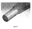
- Figure 9 shows a sleeve which is press-fitted onto a stub-axle extending from the blade. The sleeve then fits into a rotor bore which is disposed rearwardly or downstream, and preferably at a 5 degree angle so as to improve power output. The blade stub extends parallel to the blade leading edge.
- a central axis water turbine assembly in accordance with a preferred embodiment of the present invention is generally indicated at 10 and comprises a main body 12, a rotor 14 and an optional housing or cowling 16.
- the main body 12 includes an electric generator assembly 18 and the rotor 14 is mounted for rotation on a shaft 20 about a central axis.
- the rotor 14 includes a hub 22 supporting a plurality of blades 24, the present preferred embodiment shown with six blades, each blade extending from a blade root 27 mounted on the hub to a blade tip 28.
- the housing 16 When installed, the housing 16 is disposed in a position so that an inner wall encircles the rotor 14 and in some embodiments converges from a front opening 29 forward of the rotor to a narrower throat 30 adjacent the rotor 14 to direct water flow towards the rotor 14.
- the blades 24 of the rotor 14 are raked rearwardly from the blade root 27 to the blade tip 28 by a tilt angle of approximately 5°, meaning that the leading edge 31 extends rearwardly from the blade root 27 to the blade tip 28 at an angle of approximately 5° to a plane 35 perpendicular to the central axis passing through the leading edge at the blade root 27.
- Preferred tilt angles were determined using computational fluid dynamics (CFD) modelling.
- CFD computational fluid dynamics
- the graph depicted in Figure 12 shows the modelled relative power output of a turbine for various tilt angles at different flow conditions. The optimum points are when the efficiencies are at the highest for each speed. This specifies that for the turbine to run at optimum efficiency under known conditions and design criteria, the blade should have a rearward tilt angle of between 1° and 20°, preferably about 5°. While the graph indicates that optimum efficiency may be achieved with tilt angles of greater than 5°, a tilt angle of no more than about 5° is preferable to minimise bending moments at the blade root under some mechanical configurations. However, with appropriate mountings, it is envisaged that tilt angles greater than 5°, say, up to 20° or more may be employed successfully.
- water is directed by the converging cowling or housing 16 to flow toward the rotor 14.
- the rotor 14 is driven to rotate the shaft 20 about the central axis, which in turn drives the generator 18 producing electrical power output.
- the generator assembly 18 may be connected to a gearbox which in turn would be connected to the shaft, but in this preferred embodiment, the generator 18 is directly coupled to the shaft with a splined connection without requiring a gearbox.
- the shaft 20 may be of any suitable material so as to resist corrosion in an aggressive environment and to support the loadings required. Carbon steel is preferred, however, other materials may be useful, including for example, stainless steel. Furthermore, for the same protective purpose, some exposed parts of the shaft are covered with a sleeve or sheath or other prophylactic material such as for example paint. Grease or other protective material such as for example barium dichromate or the like is packed or injected into the interstitial space between the sleeve and the shaft in order to facilitate further protection of the shaft.
- a plug 40 is provided around and/or adjacent the blade root 27 so as to smooth the flow of water in the region adjacent the blade root 27 and hub.
- the plug 40 may be constructed from polyurethane and may be in the form of a flexible boot or a sealant/adhesive fluid which to install is pumped into place.
- the preferred plug 40 is shown, or one half of it, at Fig 25 .
- the hub 22 is affixed to the shaft with an interference fit so as to simplify its connection to the shaft but also to maintain security of that connection.
- Support struts 50 are connected to the cowling or housing 16 so as to support the main body 12 and rotor in a substantially central disposition in the cowling and/or housing 16. Any suitable number of support struts 50 may be used, and in the Figures shown, there are three.
- the support struts 50 may be hollow so as to house reservoirs of material such as for example grease, air or hydraulic fluid, or to form ducts for the passage of electrical cables or hydraulic oil lines and the like.
- the support struts 50 shown in Figures 1 and 5 for example, radially extend from the generator and rotor.
- the support struts 50 rotatably support the shaft 20.
- Two spaced-apart bearings are used, one upstream 51 and one downstream 53, interconnected by a bearing sleeve.
- the support struts 50 connect to the bearing sleeve at their outer diameter.
- a brake 60 is provided, which in the preferred embodiment shown, is disposed adjacent the support struts.
- the brake 60 is preferably a fail safe mechanism, wherein pressure, preferably hydraulic, is used when the turbine 10 is in use to hold a brake shoe or a resistance element such as for example a magnetic or pneumatic element, against an engagement force, out of engagement with the shaft 20. If there is a failure condition such as a blade loss, breakage, or electricity cut, or some other problem, the power to the brake is cut, either slowly or quickly, so that the engagement force drives the brake shoe or braking element into engagement or activation with the shaft 20 to slow or stop the shaft 20 and rotor 22.
- FIG. 13 is an exploded view of a preferred turbine main body 12 and rotor 14.
- the main body 12 houses the generator 18 which is directly connected to the shaft 20 via a splined connection.
- the generator 18 which in the embodiment shown is an induction motor or permanent magnet motor, which, in generator mode, is used to convert the mechanical power output from the rotation of the rotor to electrical power.
- Mechanical torque is supplied by the rotating blades 24 to the shaft 20, which induces a voltage at the stator output terminals.
- induction motors have a variable rotor flux, provided from an external source. This flux interacts with the stator flux and the difference between the rotational frequencies of the two determines the mechanical torque or induced terminal voltage when operating as a motor or generator respectively.
- blades 24 are mounted on the hub 22 of the rotor 14 and may be blades 24 having a twist angle in the order of 70° as depicted here.
- blades 24 of many different shapes and configurations can be used for the turbine 10, without departing from the spirit or ambit of the invention.
- the blades 24 can be manufactured from a mould process using fibre reinforced plastics or other compounds such as carbon fibre reinforced plastics, but can alternatively be fabricated using structural ribs and sheet skin from steel, non-ferrous alloys or fibre reinforced plastics.
- Fibre direction at the root 27 is longitudinal as shown in the Figures, in order to improve strength at that critical point.
- a nose cone 65 is mounted on the front of the hub 12 of the rotor 14 to reduce drag on the rotor 14 and to promote flow attachment.
- the nose cone 65 can be fabricated from a variety of materials, including but not limited to fibre reinforced plastics, other composites or steel.
- the nose cone may be solid, but in the preferred embodiment shown, is hollow and may provide space for reservoirs such as for example grease tanks.
- a tail cone may also be provided and may have the same functionality as the nose cone, in the preferred embodiment, being as shown in the drawings.
- a grease tank and dosing unit are provided, disposed on an upper portion of the housing, outside the throat and blades so as not to interfere with the water flow from which usable energy is extracted.
- Figure 22 shows two turbines 10 deployed on a pylon 67.
- the turbines 10 may also be deployed by other means such as but not limited to; gravity based structures or floating structures.
- the structures may or may not afford axial rotation around the vertical axis.
- the turbine housing shown in the Figures is constructed of modular components that will generally be manufactured from moulded fibre reinforced plastics in sections that are then joined together with structural fasteners.
- the turbine housing can alternatively be fabricated using structural ribs and sheet skin from steel, non-ferrous alloys or fibre reinforced plastics. The housing allows focussing of water into the turbine from currents that are not perpendicular to the plane of rotation of the blades.
- the turbine 10 can be any size. As an example, it is expected that a turbine of five meter diameter at the blades and approximately seven meters at the housing mouth, is capable of producing up to approximately 1 MW depending on water speed.
- the generator unit may produce electrical power as either alternating current (AC) or direct current (DC), and may be controlled electronically, which may allow control of electrical power output characteristics.
- Power generated by the generator means may be stored by or separately from the generator means, for example, by one or more batteries, or may be fed directly into a power system, for example, a local power system. In the latter case, synchronisation, power factor and voltage of the power generated may be regulated electronically, using a variable speed drive (VSD) for example, prior to being fed into a local power distribution mains system such as a power grid.
- VSD variable speed drive
- the generator means may be coupled by a cable, for example, a submarine cable, to the local power distribution system.
- the cowling, housing or duct 16 in preferred embodiments has a liquid or fluid flow channel therethrough and the rotor 14 is mounted in the flow channel for rotation in response to liquid/fluid (water) flow through the flow channel.
- the flow channel defines a flow restriction which can form a venturi comprising a convergent-divergent venturi, tapering from openings at either end of the flow channel towards an inner part of the flow channel.
- the housing is substantially symmetrical about a mid-point location and the rotor is located substantially at the mid-point location within the flow channel.
- the housing or duct or cowling 16 comprises a single sleeve.
- the housing or duct has a narrowed or reduced waist on an outer surface thereof between ends thereof, and in this case, substantially mid-way between the ends thereof.
- the turbine housing can comprise an outer housing sleeve and an inner housing sleeve which inner sleeve defines the flow channel.
- the housing can be secured to an underwater surface by a support or mounting structure and substantially aligned to a direction of predicted tidal or current flow.
- the angle between the actual direction of the housing and the direction of tidal or current flow can be between about 0° to about 45° or more.
- the housing as shown in the Figures, comprises sections, each of which includes flanges at their perimeters so that bolts or other fasteners such as for example adhesive tapes or glues can be used to hold them against their adjacent component.
- An inlet and/or outlet diameter of the flow channel can be in the range 1 metre to 25+ metres, depending on the amount of power generation required.
- the turbine will have a diameter of around 2 to 10 metres.
- the length of the flow channel or duct can be in the range 1 metre to 15+ metres, depending on the size of the turbine.
- the turbine housing 16 is preferably secured to an underwater surface, for example, a floor or bed of a sea, ocean or river by, for example, a mounting structure, which may be substantially aligned with the direction of tidal flow. Alternatively, the turbine housing 16 may be moveably secured to an underwater surface to allow movement to face the direction of main or tidal flow.
- the turbine unit may comprise a sub-sea turbine, but it will be appreciated that the turbine unit may be used in any underwater environment where a liquid flow exists, for example, in any tidal or river flow situation.
- An electrical cabinet 69 is provided in the preferred embodiment shown in the Figures, the cabinet being affixed to the downstream end of the generator 18.
- the generator chamber is sealed from the electrical cabinet with positive air or hydraulic fluid pressure.
- the support struts 150 are tangentially-mounted to improve torque transfer between generator and housing.
- This preferred arrangement is advantageous because it can facilitate reduction of the size of the struts, and reduces shadowing of the support struts. That is, it can be seen that radially-extending support struts 50 ( Figure 5 ) can be completely shadowed behind a radially-extending blade, each time they pass a strut 50. However, this shadowing is more gradual with a tangentially-extending blade, which also assists with improving exit flow from the trailing edge of the blade.
- the electric generator assembly 18, cabinet 6a, broke and hub and rotor can be assembled as a single module.
- the module (not shown) includes the rotor, shaft, generator, brake, hub and other associated elements suitable for mounting in the centrally-disposed module.
- the module is streamlined and may be shipped separately such as for example in a kit of parts.
- the housing may be shipped as shown in Fig 14 , wherein the mounts for the support struts are welded to the inner wall of the housing.
- the support struts are then bolted to the wall mounts and then bolted to the tangential module mounts so the module is held in place in its central position by the support struts and bolted in place.
- a kit of parts may be supplied to a site, whereupon the kit is assembled by simple bolted connections on, say, a barge, and then is installed at sea or other water flow site such as a river.
- the marine environment is extremely aggressive to materials from which the turbine assembly is constructed. Therefore several measures are taken in the preferred embodiment shown to mitigate damage to the turbine assembly.
- the housing 16 and main body 12, and various other parts are painted or otherwise coated with antifouling material to minimise growth of marine life including barnacles and other sea creatures.
- sacrificial anodes (not shown) are attached to metal components or otherwise electrically connected thereto.
- the power generator generates electrical power.
- the turbine may also be adapted to run a pump which in turn causes a generator to rotate to generate electricity through fluid being pumped by the turbine.
- the turbine includes a housing having a flow channel there through, the at least one turbine means being mounted in the flow channel for rotation in response to liquid flow through the flow channel.
- the generator means may be located separately from the turbine housing or integrated in the rotor.
- the liquid is provided from a body of water within which the turbine unit is submerged, and may be sea water or river.
Landscapes
- Engineering & Computer Science (AREA)
- General Engineering & Computer Science (AREA)
- Mechanical Engineering (AREA)
- Chemical & Material Sciences (AREA)
- Combustion & Propulsion (AREA)
- Civil Engineering (AREA)
- Power Engineering (AREA)
- Structural Engineering (AREA)
- Life Sciences & Earth Sciences (AREA)
- General Life Sciences & Earth Sciences (AREA)
- Oceanography (AREA)
- Other Liquid Machine Or Engine Such As Wave Power Use (AREA)
- Hydraulic Turbines (AREA)
Claims (11)
- Aube de générateur d'énergie électrique subaquatique à axe central (24), comprenant :une emplanture d'aube (27) ;une extrémité d'aube (28) ;un bord d'attaque (31) s'étendant de l'emplanture d'aube à l'extrémité d'aube ;un bord de fuite (33) s'étendant de l'emplanture d'aube à l'extrémité d'aube ;une corde d'emplanture d'aube définie sous forme de ligne droite entre le bord d'attaque (31) et le bord de fuite (33) à l'emplanture d'aube (27) ;une corde d'extrémité d'aube définie sous forme de ligne droite entre le bord d'attaque (31) et le bord de fuite (33) à l'extrémité d'aube (28) ;l'aube (24) étant adaptée pour la rotation autour d'un axe de rotation parallèle à un axe central d'un générateur d'énergie électrique subaquatique à axe central en réponse à un écoulement d'eau à partir d'une direction parallèle à l'axe central ;caractérisé en ce que la corde d'extrémité d'aube est déplacée angulairement par rapport à la corde d'emplanture d'aube selon un angle de torsion (β) d'entre 58° et 76°.
- Aube de générateur d'énergie électrique subaquatique à axe central selon la revendication 1, dans laquelle la corde d'extrémité d'aube est angulairement déplacée par rapport à la corde d'emplanture d'aube selon un angle de torsion (β) d'environ 70°.
- Aube de générateur d'énergie électrique subaquatique à axe central selon la revendication 1 ou 2, dans laquelle l'aube (24) est construite à partir de plastique renforcé de fibres.
- Aube de générateur d'énergie électrique subaquatique à axe central selon la revendication 3, dans laquelle les fibres s'étendent sur la longueur de l'aube (24).
- Générateur d'énergie électrique subaquatique à axe central comprenant une aube (24) selon l'une quelconque des revendications 1 à 4.
- Générateur d'énergie électrique subaquatique à axe central, comprenant :un corps de turbine possédant un axe central ;un rotor (14) fonctionnellement monté sur le corps de turbine pour la rotation autour de l'axe central, le rotor comprenant un moyeu central (22) supportant une pluralité d'aubes (24) selon l'une quelconque des revendications 1 à 4 et s'étendant d'une emplanture d'aube (27), montée sur le moyeu, à une extrémité d'aube (28) ;un générateur (18) entraîné par le rotor (14).
- Générateur d'énergie électrique subaquatique à axe central selon la revendication 6, dans lequel est prévu un logement (16) entourant le rotor (14) et adapté pour diriger un écoulement d'eau vers le rotor.
- Générateur d'énergie électrique subaquatique à axe central selon la revendication 6 ou 7, dans lequel les bords d'attaque (31) des aubes sont effilés, penchés, inclinés ou écartés vers l'arrière ou en aval, de l'emplanture d'aube (27) à l'extrémité d'aube (28), selon un angle d'inclinaison d'environ 1° à 20° par rapport à un plan perpendiculaire à l'axe central.
- Générateur d'énergie électrique subaquatique à axe central selon la revendication 7, dans lequel le logement (16) converge d'une ouverture avant (29), à l'avant du rotor (14), à un étranglement plus étroit (30) adjacent au corps de turbine.
- Générateur d'énergie électrique subaquatique à axe central selon la revendication 6 ou 7 ou 8, dans lequel les bords d'attaque (31) des aubes (24) sont écartés vers l'arrière, de l'emplanture d'aube (27) à l'extrémité d'aube (28), selon un angle d'inclinaison de 2° à 10°.
- Générateur d'énergie électrique subaquatique à axe central selon la revendication 9, dans lequel les bords d'attaque (31) des aubes (24) sont penchés de 4° à 6° par rapport au plan perpendiculaire à l'axe central.
Applications Claiming Priority (2)
| Application Number | Priority Date | Filing Date | Title |
|---|---|---|---|
| AU2008901834A AU2008901834A0 (en) | 2008-04-14 | Turbine Blade | |
| PCT/AU2009/000458 WO2009126996A1 (fr) | 2008-04-14 | 2009-04-14 | Aube pour turbine à eau |
Publications (3)
| Publication Number | Publication Date |
|---|---|
| EP2304225A1 EP2304225A1 (fr) | 2011-04-06 |
| EP2304225A4 EP2304225A4 (fr) | 2013-03-20 |
| EP2304225B1 true EP2304225B1 (fr) | 2015-10-14 |
Family
ID=41198689
Family Applications (1)
| Application Number | Title | Priority Date | Filing Date |
|---|---|---|---|
| EP09732944.5A Not-in-force EP2304225B1 (fr) | 2008-04-14 | 2009-04-14 | Aube pour turbine à eau |
Country Status (8)
| Country | Link |
|---|---|
| US (1) | US8801386B2 (fr) |
| EP (1) | EP2304225B1 (fr) |
| KR (1) | KR101284236B1 (fr) |
| CN (1) | CN102066744B (fr) |
| AU (1) | AU2009238206B2 (fr) |
| CA (1) | CA2724693C (fr) |
| CL (1) | CL2009000892A1 (fr) |
| WO (1) | WO2009126996A1 (fr) |
Families Citing this family (29)
| Publication number | Priority date | Publication date | Assignee | Title |
|---|---|---|---|---|
| EP2212548A4 (fr) * | 2007-11-23 | 2011-02-23 | Atlantis Resources Corp Pte | Système de commande pour extraire de l'énergie électrique à partir d'un écoulement d'eau |
| WO2009126995A1 (fr) | 2008-04-14 | 2009-10-22 | Atlantis Resources Corporation Pte Limited | Turbine à eau à axe central |
| KR20120042746A (ko) | 2009-04-28 | 2012-05-03 | 아틀란티스 리소시스 코포레이션 피티이 리미티드 | 수중 동력 발생기 |
| CA2776533A1 (fr) | 2009-10-27 | 2011-05-05 | Atlantis Resources Corporation Pte Limited | Generateur d'electricite immerge |
| DE102010048944A1 (de) * | 2009-10-30 | 2011-05-05 | Ksb Aktiengesellschaft | Saugrohr |
| GB201001527D0 (en) * | 2010-01-29 | 2010-03-17 | Blade Dynamics Ltd | A blade for a turbine operating in water |
| ITMI20100160A1 (it) * | 2010-02-03 | 2011-08-04 | Tecnedil Srl | Apparecchiatura per la generazione di energia elettrica attraverso lo sfruttamento delle correnti marine e dei corsi d'acqua in generale. |
| FR2965591B1 (fr) | 2010-09-30 | 2012-08-31 | Alstom Hydro France | Poutre de supportage d'un carenage d'hydrolienne et hydrolienne comportant une telle poutre |
| DK2630366T3 (en) * | 2010-10-22 | 2018-10-29 | Wave Power Renewables Ltd | Turbine rotor unit |
| KR20140034818A (ko) | 2011-05-10 | 2014-03-20 | 아틀란티스 리소시스 코포레이션 피티이 리미티드 | 수중 발전기를 전개하는 장치 및 방법 |
| US9140126B2 (en) * | 2011-07-26 | 2015-09-22 | Anthony V. Hins | Propeller with reactionary and vacuum faces |
| KR101302164B1 (ko) * | 2011-11-21 | 2013-08-30 | 주식회사 금성이앤씨 | 발전용 터빈의 런너 블레이드 |
| CN103423075A (zh) * | 2012-05-17 | 2013-12-04 | 厦门锐思达机电科技有限公司 | 一种潮汐能发电模块及阵列 |
| GB201215004D0 (en) | 2012-08-23 | 2012-10-10 | Blade Dynamics Ltd | Wind turbine tower |
| GB201217212D0 (en) | 2012-09-26 | 2012-11-07 | Blade Dynamics Ltd | Windturbine blade |
| GB201217210D0 (en) | 2012-09-26 | 2012-11-07 | Blade Dynamics Ltd | A metod of forming a structural connection between a spar cap fairing for a wind turbine blade |
| CL2014002818A1 (es) * | 2014-10-20 | 2014-11-28 | Marcelo Pavez Vasquez Claudio | Sistema para compensación de peso, sujeción y amarre de turbinas de generación mareomotriz, comprende un cilindro hidrodinámico de compensación de peso y un reticulado de amarre con forma de paralelepípedo rectangular que permite el amarre y operación del cilindro hidrodinámico de compensación de peso. |
| US20160146088A1 (en) * | 2014-11-20 | 2016-05-26 | Jeff Richardson | Cooling Fan Assembly |
| CN105257596B (zh) * | 2015-09-28 | 2016-06-15 | 北京图正实验室科技有限公司 | 鸟翅型高压轴流风机叶片及其对旋轴流风机 |
| US20180051667A1 (en) * | 2016-08-17 | 2018-02-22 | Kai-Te YANG | Flowing water hydroelectric generator |
| CN109580785A (zh) * | 2017-09-29 | 2019-04-05 | 上海金艺检测技术有限公司 | 用于汽轮机叶片根部缺陷的扫查工装及方法 |
| CN108757270B (zh) * | 2018-07-10 | 2024-01-09 | 江苏新扬新材料股份有限公司 | 一体化成型复合材料桨叶结构 |
| FR3087699B1 (fr) * | 2018-10-30 | 2021-11-26 | Safran Aircraft Engines | Hybridation des fibres du renfort fibreux d'une aube |
| WO2021167664A2 (fr) | 2019-11-22 | 2021-08-26 | Gradiant Corporation | Turbines et composants, systèmes et procédés associés |
| USD929929S1 (en) | 2019-12-20 | 2021-09-07 | Gary Alan Ledford | Flap for propeller blade |
| NL2025538B1 (en) | 2020-05-08 | 2021-11-23 | Equinox Ocean Turbines B V | Turbine with secondary rotors |
| CN116291747A (zh) * | 2021-12-03 | 2023-06-23 | 中国地质大学(北京) | 一种矩形流道涡轮与正倾叶片及其成型方法及涡轮钻具 |
| WO2023245079A1 (fr) * | 2022-06-16 | 2023-12-21 | Littoral Power Systems, Inc. | Dispositif à énergie hydrocinétique |
| USD1063789S1 (en) * | 2024-01-16 | 2025-02-25 | Turtle Pump Company LLC | Propeller blade |
Family Cites Families (115)
| Publication number | Priority date | Publication date | Assignee | Title |
|---|---|---|---|---|
| US1025929A (en) | 1911-07-13 | 1912-05-07 | Henry J Snook | Wave-motor. |
| US1371836A (en) | 1919-10-21 | 1921-03-15 | Antz Eugene | Current-motor |
| US1546554A (en) * | 1922-09-16 | 1925-07-21 | Ross Propeller Corp | Screw propeller |
| US2280148A (en) | 1940-08-28 | 1942-04-21 | Dough King Inc | Doughnut machine |
| US3139166A (en) | 1960-02-08 | 1964-06-30 | Dominion Eng Works Ltd | Overspeed prevention device |
| FR1353655A (fr) | 1963-01-19 | 1964-02-28 | Grenobloise Etude Appl | Hydroréacteur |
| US3604942A (en) | 1970-05-11 | 1971-09-14 | Curtis A Nelson | Underwater generator |
| CH541065A (de) * | 1972-01-20 | 1973-08-31 | Bbc Brown Boveri & Cie | Verdrillte Laufschaufel einer axial durchströmten Turbomaschine |
| US3942231A (en) | 1973-10-31 | 1976-03-09 | Trw Inc. | Contour formed metal matrix blade plies |
| US3986787A (en) | 1974-05-07 | 1976-10-19 | Mouton Jr William J | River turbine |
| US3986792A (en) * | 1975-03-03 | 1976-10-19 | Westinghouse Electric Corporation | Vibration dampening device disposed on a shroud member for a twisted turbine blade |
| AR216286A1 (es) | 1975-07-14 | 1979-12-14 | Gutierrez Atencio F | Conjunto hidromotriz transportatable |
| US4075500A (en) | 1975-08-13 | 1978-02-21 | Grumman Aerospace Corporation | Variable stator, diffuser augmented wind turbine electrical generation system |
| US4021135A (en) | 1975-10-09 | 1977-05-03 | Pedersen Nicholas F | Wind turbine |
| CH606801A5 (fr) | 1975-12-02 | 1978-11-15 | Escher Wyss Ag | |
| GB1518151A (en) | 1976-05-14 | 1978-07-19 | Peck A | Energy extracting machine |
| US4258271A (en) | 1977-05-19 | 1981-03-24 | Chappell Walter L | Power converter and method |
| US4207015A (en) | 1978-02-23 | 1980-06-10 | Atencio Francisco J G | Self-stabilized hydromotive assembly |
| AT359941B (de) | 1979-01-18 | 1980-12-10 | Buchelt Benno | Wasserturbine |
| US4503673A (en) | 1979-05-25 | 1985-03-12 | Charles Schachle | Wind power generating system |
| US4306157A (en) | 1979-06-20 | 1981-12-15 | Wracsaricht Lazar J | Underwater slow current turbo generator |
| US4256970A (en) | 1979-06-25 | 1981-03-17 | Eugene Pascucci | Apparatus for the exploitation of underwater currents for the production of electrical energy |
| US4524285A (en) | 1979-09-14 | 1985-06-18 | Rauch Hans G | Hydro-current energy converter |
| US4324985A (en) | 1980-07-09 | 1982-04-13 | Grumman Aerospace Corp. | Portable wind turbine for charging batteries |
| US4352989A (en) | 1980-08-19 | 1982-10-05 | Gutierrez Atencio Francisco J | Hydromotive set |
| US4460531A (en) * | 1982-05-10 | 1984-07-17 | The Boeing Company | Composite fiber reinforced propeller |
| DE3403805C2 (de) | 1984-02-03 | 1986-01-16 | Georg Dr.-Ing. 8152 Feldkirchen-Westerham Spinner | Verbindungsvorrichtung für Koaxialkabel |
| US4613279A (en) * | 1984-03-22 | 1986-09-23 | Riverside Energy Technology, Inc. | Kinetic hydro energy conversion system |
| US4722665A (en) | 1984-11-07 | 1988-02-02 | Tyson Warren N | Turbine |
| US4695736A (en) | 1985-11-18 | 1987-09-22 | United Technologies Corporation | Variable speed wind turbine |
| US5506453A (en) | 1990-02-09 | 1996-04-09 | Mccombs; John C. | Machine for converting wind energy to electrical energy |
| GB2265672B (en) | 1992-03-18 | 1995-11-22 | Advanced Wind Turbines Inc | Wind turbines |
| GB9210421D0 (en) | 1992-05-15 | 1992-07-01 | Gec Alsthom Ltd | Turbine blade assembly |
| US5642984A (en) | 1994-01-11 | 1997-07-01 | Northeastern University | Helical turbine assembly operable under multidirectional fluid flow for power and propulsion systems |
| US5531567A (en) * | 1994-06-20 | 1996-07-02 | Flowind Corporation | Vertical axis wind turbine with blade tensioner |
| US5440176A (en) | 1994-10-18 | 1995-08-08 | Haining Michael L | Ocean current power generator |
| US5947679A (en) | 1996-03-28 | 1999-09-07 | Voith Hydro, Inc. | Adjustable blade turbines |
| US5954474A (en) | 1996-03-28 | 1999-09-21 | Voith Hydro, Inc. | Hydro-turbine runner |
| US5681146A (en) * | 1996-10-04 | 1997-10-28 | Future Sea Farms Inc. | Low head pumping system for fish farms |
| CA2217826C (fr) * | 1997-02-12 | 2001-12-11 | Voith Hydro, Inc. | Aube orientable de turbine hydraulique |
| DE19719406C1 (de) | 1997-05-12 | 1998-11-19 | Voith Hydro Gmbh & Co Kg | Verfahren zum Betreiben einer hydraulischen Maschine |
| US5929531A (en) | 1997-05-19 | 1999-07-27 | William Joseph Lagno | Lunar tide powered hydroelectric plant |
| US5921745A (en) | 1997-09-29 | 1999-07-13 | Hydroenergy Corporation | Low head turbine |
| PT102088B (pt) | 1997-12-11 | 2004-06-30 | Dos Santos Costa Antonio Jose | Hidroreactor destinado ao aproveitamento da energia cinetica da agua em locais s onde as correntes sejam significativas para producao de energia electrica |
| US6091161A (en) | 1998-11-03 | 2000-07-18 | Dehlsen Associates, L.L.C. | Method of controlling operating depth of an electricity-generating device having a tethered water current-driven turbine |
| DE60014071T2 (de) | 1999-02-24 | 2005-11-24 | Marine Current Turbines Ltd. | Um eine hülse angeordnete wasserströmungsturbine |
| JP4458641B2 (ja) | 1999-08-20 | 2010-04-28 | 株式会社東芝 | 軸流水車発電装置 |
| NL1013559C2 (nl) | 1999-11-11 | 2001-05-28 | Peter Alexander Josephus Pas | Systeem voor het uit water produceren van waterstof onder gebruikmaking van een waterstroom zoals een golfstroom of getijdenstroom. |
| JP2001187997A (ja) | 1999-12-28 | 2001-07-10 | Shuhei Izumi | 垂直部材立設用台座 |
| KR100874046B1 (ko) | 1999-12-29 | 2008-12-12 | 쥐씨케이 테크놀로지, 인코포레이티드 | 자유 흐름수 터빈 |
| DK174156B1 (da) | 2000-04-03 | 2002-07-29 | Henrik Frans Christensen | Vind- og bølgeenergianlæg |
| US6476513B1 (en) | 2000-09-28 | 2002-11-05 | Lubomir B. Gueorguiev | Electrical generator system |
| NO322927B1 (no) | 2001-02-13 | 2006-12-18 | Hammerfest Strom As | Anordning for produksjon av energi fra strommer i vannmasser, en forankring, samt fremgangsmate for installasjon av anordningen |
| CA2438041C (fr) | 2001-02-13 | 2010-05-11 | Hammerfest Strom As | Appareil destine a la production d'energie a partir de courants dans l'eau en ecoulement et procede d'installation de l'appareil |
| JP2002256810A (ja) * | 2001-03-05 | 2002-09-11 | Toshiba Corp | 軸流タービン |
| US6616402B2 (en) | 2001-06-14 | 2003-09-09 | Douglas Spriggs Selsam | Serpentine wind turbine |
| US6856036B2 (en) | 2001-06-26 | 2005-02-15 | Sidney Irving Belinsky | Installation for harvesting ocean currents (IHOC) |
| JP4024208B2 (ja) * | 2001-09-17 | 2007-12-19 | クリーン カーレント パワー システムズ インコーポレイテッド | 水中用ダクテッドタービン |
| US6846160B2 (en) | 2001-10-12 | 2005-01-25 | Hitachi, Ltd. | Turbine bucket |
| JP3465246B2 (ja) | 2001-11-08 | 2003-11-10 | 学校法人東海大学 | 流体発電装置 |
| AT411093B (de) * | 2001-12-07 | 2003-09-25 | Va Tech Hydro Gmbh & Co | Einrichtung und verfahren zur erzeugung elektrischer energie |
| CN1284928C (zh) | 2001-12-28 | 2006-11-15 | 三菱重工业株式会社 | 逆风型风力涡轮机及其操作方法 |
| JP2005517123A (ja) | 2002-02-05 | 2005-06-09 | イ サン チョル | 風力発電装置 |
| DE10227404B4 (de) | 2002-06-20 | 2008-05-21 | Krüger, Wolfgang | Antriebsrotor für vertikal laufende Windkraftanlagen |
| OA13205A (fr) | 2002-11-22 | 2006-12-13 | Michel Fonfrede | Roue hydraulique. |
| WO2004061297A1 (fr) | 2002-12-27 | 2004-07-22 | Baba Technical Laboratory Inc. | Dispositif de production d'energie eolienne |
| EP1462610A1 (fr) * | 2003-03-28 | 2004-09-29 | Siemens Aktiengesellschaft | Série d'aubes de rotor pour turbomachines |
| US7218011B2 (en) | 2003-04-16 | 2007-05-15 | Composite Support & Solutions, Inc. | Diffuser-augmented wind turbine |
| US7095597B1 (en) | 2003-04-30 | 2006-08-22 | Clipper Windpower Technology, Inc. | Distributed static var compensation (DSVC) system for wind and water turbine applications |
| EP1642005B1 (fr) | 2003-07-09 | 2009-10-14 | Siemens Aktiengesellschaft | Aube de turbine |
| NL1023999C1 (nl) | 2003-07-25 | 2005-01-26 | Dixi Holding B V | Verbeterde verticale as waterturbine, hydro-turby genoemd. |
| US6956300B2 (en) | 2003-08-04 | 2005-10-18 | Andrew Roman Gizara | Gimbal-mounted hydroelectric turbine |
| GB0325433D0 (en) | 2003-10-31 | 2003-12-03 | Embley Energy Ltd | A mechanism to increase the efficiency of machines designed to abstract energy from oscillating fluids |
| US7872365B2 (en) | 2004-11-09 | 2011-01-18 | Rourke Gerald S | Wave powered electrical generator |
| US7088012B2 (en) | 2004-12-21 | 2006-08-08 | Andrew Roman Gizara | Transverse hydroelectric generator |
| US20080124217A1 (en) | 2004-12-27 | 2008-05-29 | Kevin Friesth | Multi-Turbine Airflow Amplifying Generator |
| GB0510417D0 (en) | 2005-05-21 | 2005-06-29 | Rotech Holdings Ltd | Improved turbine |
| US7199484B2 (en) | 2005-07-05 | 2007-04-03 | Gencor Industries Inc. | Water current generator |
| GB2431628B (en) | 2005-10-31 | 2009-01-28 | Tidal Generation Ltd | A deployment and retrieval apparatus for submerged power generating devices |
| KR100737269B1 (ko) | 2005-12-06 | 2007-07-12 | 허현강 | 대형 양방향 풍력발전기 |
| US7470086B2 (en) | 2006-01-04 | 2008-12-30 | Clifford Allen Jennings | Submersible tethered platform for undersea electrical power generation |
| US20070191973A1 (en) | 2006-02-10 | 2007-08-16 | General Electric Company | Apparatus and method for configuring, processing and viewing state based data |
| US20070241566A1 (en) | 2006-02-28 | 2007-10-18 | Kuehnle Manfred R | Submersible turbine apparatus |
| WO2007111517A2 (fr) * | 2006-03-24 | 2007-10-04 | Pacer Turbines Limited | Generateur d'electricite |
| US20070231117A1 (en) | 2006-04-03 | 2007-10-04 | Alexander Gokhman | Two-way generation tidal power plant with one-way turbines |
| US20070231148A1 (en) | 2006-04-03 | 2007-10-04 | Lehoczky Kalman N | Reversing free flow propeller turbine |
| EP2327873A1 (fr) | 2006-04-28 | 2011-06-01 | Swanturbines Limited | Turbine maremotrice |
| GB0608367D0 (en) | 2006-04-28 | 2006-06-07 | Uws Ventures Ltd | Plug system |
| JP5005762B2 (ja) | 2006-06-02 | 2012-08-22 | セッポ・リューネネン | 波のエネルギーを流れ抵抗形状係数の違いによって電気に変換する方法および装置 |
| US7489046B2 (en) | 2006-06-08 | 2009-02-10 | Northern Power Systems, Inc. | Water turbine system and method of operation |
| US7686583B2 (en) | 2006-07-10 | 2010-03-30 | Siegel Aerodynamics, Inc. | Cyclical wave energy converter |
| US7891953B2 (en) | 2006-09-05 | 2011-02-22 | Verdant Power | Rotating wedge leveler |
| JP5508018B2 (ja) | 2006-10-20 | 2014-05-28 | オーシヤン・リニユーアブル・パワー・カンパニー・エルエルシー | 海流及び潮汐流用の潜水可能なタービン発電機ユニット |
| US7789629B2 (en) | 2006-12-07 | 2010-09-07 | Verdant Power | Non-fouling kinetic hydro power system axial-flow blade tip treatment |
| GB0700128D0 (en) | 2007-01-04 | 2007-02-14 | Power Ltd C | Tidal electricity generating apparatus |
| NO327567B1 (no) | 2007-02-16 | 2009-08-17 | Hydra Tidal Energy Technology | Flytende anlegg for produksjon av energi fra stromninger i vann |
| WO2008115558A1 (fr) | 2007-03-20 | 2008-09-25 | Zeuner Kenneth W | Système et procédé pour collecter la puissance électrique du courant marin en utilisant des turbines |
| US20080236159A1 (en) | 2007-03-27 | 2008-10-02 | Glenn Martin Tierney | Cycloidal power generator |
| GB2448710B (en) | 2007-04-24 | 2009-03-11 | Tidal Generation Ltd | A Mechanical connection system for submerged marine power generating devices |
| ES2343447B1 (es) | 2007-04-26 | 2011-05-20 | M.Torres Olvega Industrial, S.L. | Aerogenerador de alta produccion electrica. |
| KR20100061453A (ko) | 2007-07-25 | 2010-06-07 | 트루라이트 인크. | 하이브리드 전력의 생성 및 사용을 관리하는 장치, 시스템 및 방법 |
| WO2009015419A1 (fr) | 2007-07-30 | 2009-02-05 | Buoyancy Hydro Pty Ltd | Générateur d'énergie hydraulique par poussée d'archimède et procédé correspondant |
| US8303241B2 (en) | 2007-11-13 | 2012-11-06 | Verdant Power, Inc. | Turbine yaw control |
| EP2212548A4 (fr) | 2007-11-23 | 2011-02-23 | Atlantis Resources Corp Pte | Système de commande pour extraire de l'énergie électrique à partir d'un écoulement d'eau |
| DE102008000382A1 (de) | 2008-02-22 | 2009-09-03 | Ed. Züblin Ag | Richtungskorrekturelement zum Ausgleich von Schiefstellungen von Gründungen bei Windenergieanlagen und Verfahren zur Richtungskorrektur |
| WO2009126995A1 (fr) | 2008-04-14 | 2009-10-22 | Atlantis Resources Corporation Pte Limited | Turbine à eau à axe central |
| US20100066089A1 (en) | 2008-09-12 | 2010-03-18 | Bruce Best | Subsea turbine with a peripheral drive |
| KR20120042746A (ko) | 2009-04-28 | 2012-05-03 | 아틀란티스 리소시스 코포레이션 피티이 리미티드 | 수중 동력 발생기 |
| JP5639641B2 (ja) | 2009-04-28 | 2014-12-10 | アトランティス リソーセズ コーポレーション ピーティーイー リミテッド | 双方向タービンブレード |
| AU2010251700B2 (en) | 2009-05-22 | 2013-10-03 | Atlantis Resources Corporation Pte Limited | Improvements to control of underwater turbine |
| GB0910867D0 (en) | 2009-06-24 | 2009-08-05 | Design Tech & Innovation Ltd | Water power generators |
| CN102482858A (zh) | 2009-09-08 | 2012-05-30 | 亚特兰蒂斯能源有限公司 | 发电机 |
| AU2010312314B2 (en) | 2009-10-26 | 2013-08-22 | Atlantis Resources Corporation Pte Limited | Underwater power generator |
| CA2776533A1 (fr) | 2009-10-27 | 2011-05-05 | Atlantis Resources Corporation Pte Limited | Generateur d'electricite immerge |
| US20120086207A1 (en) | 2010-10-07 | 2012-04-12 | Dennis John Gray | Simplified Paddlewheel Energy Device |
-
2009
- 2009-04-14 EP EP09732944.5A patent/EP2304225B1/fr not_active Not-in-force
- 2009-04-14 CA CA2724693A patent/CA2724693C/fr not_active Expired - Fee Related
- 2009-04-14 AU AU2009238206A patent/AU2009238206B2/en not_active Ceased
- 2009-04-14 CL CL2009000892A patent/CL2009000892A1/es unknown
- 2009-04-14 US US12/993,652 patent/US8801386B2/en not_active Expired - Fee Related
- 2009-04-14 KR KR1020107025661A patent/KR101284236B1/ko not_active Expired - Fee Related
- 2009-04-14 WO PCT/AU2009/000458 patent/WO2009126996A1/fr not_active Ceased
- 2009-04-14 CN CN200980122382.2A patent/CN102066744B/zh not_active Expired - Fee Related
Also Published As
| Publication number | Publication date |
|---|---|
| US20110176915A1 (en) | 2011-07-21 |
| WO2009126996A1 (fr) | 2009-10-22 |
| EP2304225A1 (fr) | 2011-04-06 |
| KR20100134757A (ko) | 2010-12-23 |
| CA2724693A1 (fr) | 2009-10-22 |
| CL2009000892A1 (es) | 2010-03-05 |
| US8801386B2 (en) | 2014-08-12 |
| CN102066744A (zh) | 2011-05-18 |
| AU2009238206B2 (en) | 2013-03-14 |
| AU2009238206A1 (en) | 2009-10-22 |
| KR101284236B1 (ko) | 2013-07-09 |
| CA2724693C (fr) | 2013-01-22 |
| CN102066744B (zh) | 2014-07-23 |
| EP2304225A4 (fr) | 2013-03-20 |
Similar Documents
| Publication | Publication Date | Title |
|---|---|---|
| EP2304225B1 (fr) | Aube pour turbine à eau | |
| CA2724702C (fr) | Turbine a eau a axe central dotee de pales en rateau inclinees vers l'arriere | |
| US8664790B2 (en) | Underwater power generator with dual blade sets | |
| AU2008323632B2 (en) | A power generator | |
| KR102358885B1 (ko) | 수력 발전/유체 동력학 터빈 및 이를 제조 및 사용하기 위한 방법 | |
| AU2008323631A1 (en) | A power generator |
Legal Events
| Date | Code | Title | Description |
|---|---|---|---|
| PUAI | Public reference made under article 153(3) epc to a published international application that has entered the european phase |
Free format text: ORIGINAL CODE: 0009012 |
|
| 17P | Request for examination filed |
Effective date: 20101115 |
|
| AK | Designated contracting states |
Kind code of ref document: A1 Designated state(s): AT BE BG CH CY CZ DE DK EE ES FI FR GB GR HR HU IE IS IT LI LT LU LV MC MK MT NL NO PL PT RO SE SI SK TR |
|
| AX | Request for extension of the european patent |
Extension state: AL BA RS |
|
| DAX | Request for extension of the european patent (deleted) | ||
| RIN1 | Information on inventor provided before grant (corrected) |
Inventor name: KEIR, JOHN Inventor name: SRIGRAROM, SUTTHIPHONG |
|
| A4 | Supplementary search report drawn up and despatched |
Effective date: 20130219 |
|
| RIC1 | Information provided on ipc code assigned before grant |
Ipc: F03B 17/06 20060101ALI20130213BHEP Ipc: F01D 5/14 20060101ALI20130213BHEP Ipc: F01D 5/12 20060101ALI20130213BHEP Ipc: E02B 9/00 20060101ALI20130213BHEP Ipc: F03B 13/10 20060101ALI20130213BHEP Ipc: F03B 3/12 20060101AFI20130213BHEP Ipc: F03B 13/26 20060101ALI20130213BHEP Ipc: F03D 11/00 20060101ALI20130213BHEP |
|
| GRAP | Despatch of communication of intention to grant a patent |
Free format text: ORIGINAL CODE: EPIDOSNIGR1 |
|
| RIC1 | Information provided on ipc code assigned before grant |
Ipc: F03B 13/26 20060101ALI20150504BHEP Ipc: F01D 5/14 20060101ALI20150504BHEP Ipc: F03B 17/06 20060101ALI20150504BHEP Ipc: F03D 11/00 20060101ALI20150504BHEP Ipc: E02B 9/00 20060101ALI20150504BHEP Ipc: F01D 5/12 20060101ALI20150504BHEP Ipc: F03B 3/12 20060101AFI20150504BHEP Ipc: F03B 13/10 20060101ALI20150504BHEP |
|
| INTG | Intention to grant announced |
Effective date: 20150609 |
|
| GRAS | Grant fee paid |
Free format text: ORIGINAL CODE: EPIDOSNIGR3 |
|
| GRAA | (expected) grant |
Free format text: ORIGINAL CODE: 0009210 |
|
| AK | Designated contracting states |
Kind code of ref document: B1 Designated state(s): AT BE BG CH CY CZ DE DK EE ES FI FR GB GR HR HU IE IS IT LI LT LU LV MC MK MT NL NO PL PT RO SE SI SK TR |
|
| REG | Reference to a national code |
Ref country code: GB Ref legal event code: FG4D |
|
| REG | Reference to a national code |
Ref country code: AT Ref legal event code: REF Ref document number: 755320 Country of ref document: AT Kind code of ref document: T Effective date: 20151015 Ref country code: CH Ref legal event code: EP |
|
| REG | Reference to a national code |
Ref country code: IE Ref legal event code: FG4D |
|
| REG | Reference to a national code |
Ref country code: DE Ref legal event code: R096 Ref document number: 602009034216 Country of ref document: DE |
|
| REG | Reference to a national code |
Ref country code: NL Ref legal event code: MP Effective date: 20151014 |
|
| REG | Reference to a national code |
Ref country code: LT Ref legal event code: MG4D |
|
| REG | Reference to a national code |
Ref country code: AT Ref legal event code: MK05 Ref document number: 755320 Country of ref document: AT Kind code of ref document: T Effective date: 20151014 |
|
| PG25 | Lapsed in a contracting state [announced via postgrant information from national office to epo] |
Ref country code: IS Free format text: LAPSE BECAUSE OF FAILURE TO SUBMIT A TRANSLATION OF THE DESCRIPTION OR TO PAY THE FEE WITHIN THE PRESCRIBED TIME-LIMIT Effective date: 20160214 Ref country code: LT Free format text: LAPSE BECAUSE OF FAILURE TO SUBMIT A TRANSLATION OF THE DESCRIPTION OR TO PAY THE FEE WITHIN THE PRESCRIBED TIME-LIMIT Effective date: 20151014 Ref country code: IT Free format text: LAPSE BECAUSE OF FAILURE TO SUBMIT A TRANSLATION OF THE DESCRIPTION OR TO PAY THE FEE WITHIN THE PRESCRIBED TIME-LIMIT Effective date: 20151014 Ref country code: NL Free format text: LAPSE BECAUSE OF FAILURE TO SUBMIT A TRANSLATION OF THE DESCRIPTION OR TO PAY THE FEE WITHIN THE PRESCRIBED TIME-LIMIT Effective date: 20151014 Ref country code: NO Free format text: LAPSE BECAUSE OF FAILURE TO SUBMIT A TRANSLATION OF THE DESCRIPTION OR TO PAY THE FEE WITHIN THE PRESCRIBED TIME-LIMIT Effective date: 20160114 Ref country code: HR Free format text: LAPSE BECAUSE OF FAILURE TO SUBMIT A TRANSLATION OF THE DESCRIPTION OR TO PAY THE FEE WITHIN THE PRESCRIBED TIME-LIMIT Effective date: 20151014 Ref country code: ES Free format text: LAPSE BECAUSE OF FAILURE TO SUBMIT A TRANSLATION OF THE DESCRIPTION OR TO PAY THE FEE WITHIN THE PRESCRIBED TIME-LIMIT Effective date: 20151014 |
|
| PG25 | Lapsed in a contracting state [announced via postgrant information from national office to epo] |
Ref country code: AT Free format text: LAPSE BECAUSE OF FAILURE TO SUBMIT A TRANSLATION OF THE DESCRIPTION OR TO PAY THE FEE WITHIN THE PRESCRIBED TIME-LIMIT Effective date: 20151014 Ref country code: FI Free format text: LAPSE BECAUSE OF FAILURE TO SUBMIT A TRANSLATION OF THE DESCRIPTION OR TO PAY THE FEE WITHIN THE PRESCRIBED TIME-LIMIT Effective date: 20151014 Ref country code: PT Free format text: LAPSE BECAUSE OF FAILURE TO SUBMIT A TRANSLATION OF THE DESCRIPTION OR TO PAY THE FEE WITHIN THE PRESCRIBED TIME-LIMIT Effective date: 20160215 Ref country code: LV Free format text: LAPSE BECAUSE OF FAILURE TO SUBMIT A TRANSLATION OF THE DESCRIPTION OR TO PAY THE FEE WITHIN THE PRESCRIBED TIME-LIMIT Effective date: 20151014 Ref country code: SE Free format text: LAPSE BECAUSE OF FAILURE TO SUBMIT A TRANSLATION OF THE DESCRIPTION OR TO PAY THE FEE WITHIN THE PRESCRIBED TIME-LIMIT Effective date: 20151014 Ref country code: PL Free format text: LAPSE BECAUSE OF FAILURE TO SUBMIT A TRANSLATION OF THE DESCRIPTION OR TO PAY THE FEE WITHIN THE PRESCRIBED TIME-LIMIT Effective date: 20151014 Ref country code: GR Free format text: LAPSE BECAUSE OF FAILURE TO SUBMIT A TRANSLATION OF THE DESCRIPTION OR TO PAY THE FEE WITHIN THE PRESCRIBED TIME-LIMIT Effective date: 20160115 |
|
| REG | Reference to a national code |
Ref country code: DE Ref legal event code: R097 Ref document number: 602009034216 Country of ref document: DE |
|
| PG25 | Lapsed in a contracting state [announced via postgrant information from national office to epo] |
Ref country code: CZ Free format text: LAPSE BECAUSE OF FAILURE TO SUBMIT A TRANSLATION OF THE DESCRIPTION OR TO PAY THE FEE WITHIN THE PRESCRIBED TIME-LIMIT Effective date: 20151014 |
|
| PLBE | No opposition filed within time limit |
Free format text: ORIGINAL CODE: 0009261 |
|
| STAA | Information on the status of an ep patent application or granted ep patent |
Free format text: STATUS: NO OPPOSITION FILED WITHIN TIME LIMIT |
|
| PG25 | Lapsed in a contracting state [announced via postgrant information from national office to epo] |
Ref country code: BE Free format text: LAPSE BECAUSE OF NON-PAYMENT OF DUE FEES Effective date: 20160430 Ref country code: RO Free format text: LAPSE BECAUSE OF FAILURE TO SUBMIT A TRANSLATION OF THE DESCRIPTION OR TO PAY THE FEE WITHIN THE PRESCRIBED TIME-LIMIT Effective date: 20151014 Ref country code: SK Free format text: LAPSE BECAUSE OF FAILURE TO SUBMIT A TRANSLATION OF THE DESCRIPTION OR TO PAY THE FEE WITHIN THE PRESCRIBED TIME-LIMIT Effective date: 20151014 Ref country code: EE Free format text: LAPSE BECAUSE OF FAILURE TO SUBMIT A TRANSLATION OF THE DESCRIPTION OR TO PAY THE FEE WITHIN THE PRESCRIBED TIME-LIMIT Effective date: 20151014 Ref country code: DK Free format text: LAPSE BECAUSE OF FAILURE TO SUBMIT A TRANSLATION OF THE DESCRIPTION OR TO PAY THE FEE WITHIN THE PRESCRIBED TIME-LIMIT Effective date: 20151014 |
|
| 26N | No opposition filed |
Effective date: 20160715 |
|
| REG | Reference to a national code |
Ref country code: DE Ref legal event code: R119 Ref document number: 602009034216 Country of ref document: DE |
|
| PG25 | Lapsed in a contracting state [announced via postgrant information from national office to epo] |
Ref country code: SI Free format text: LAPSE BECAUSE OF FAILURE TO SUBMIT A TRANSLATION OF THE DESCRIPTION OR TO PAY THE FEE WITHIN THE PRESCRIBED TIME-LIMIT Effective date: 20151014 |
|
| REG | Reference to a national code |
Ref country code: CH Ref legal event code: PL |
|
| GBPC | Gb: european patent ceased through non-payment of renewal fee |
Effective date: 20160414 |
|
| PG25 | Lapsed in a contracting state [announced via postgrant information from national office to epo] |
Ref country code: LU Free format text: LAPSE BECAUSE OF FAILURE TO SUBMIT A TRANSLATION OF THE DESCRIPTION OR TO PAY THE FEE WITHIN THE PRESCRIBED TIME-LIMIT Effective date: 20160414 Ref country code: BE Free format text: LAPSE BECAUSE OF FAILURE TO SUBMIT A TRANSLATION OF THE DESCRIPTION OR TO PAY THE FEE WITHIN THE PRESCRIBED TIME-LIMIT Effective date: 20151014 |
|
| REG | Reference to a national code |
Ref country code: IE Ref legal event code: MM4A |
|
| REG | Reference to a national code |
Ref country code: FR Ref legal event code: ST Effective date: 20161230 |
|
| PG25 | Lapsed in a contracting state [announced via postgrant information from national office to epo] |
Ref country code: FR Free format text: LAPSE BECAUSE OF NON-PAYMENT OF DUE FEES Effective date: 20160502 Ref country code: GB Free format text: LAPSE BECAUSE OF NON-PAYMENT OF DUE FEES Effective date: 20160414 Ref country code: CH Free format text: LAPSE BECAUSE OF NON-PAYMENT OF DUE FEES Effective date: 20160430 Ref country code: LI Free format text: LAPSE BECAUSE OF NON-PAYMENT OF DUE FEES Effective date: 20160430 Ref country code: DE Free format text: LAPSE BECAUSE OF NON-PAYMENT OF DUE FEES Effective date: 20161101 |
|
| PG25 | Lapsed in a contracting state [announced via postgrant information from national office to epo] |
Ref country code: IE Free format text: LAPSE BECAUSE OF NON-PAYMENT OF DUE FEES Effective date: 20160414 |
|
| PG25 | Lapsed in a contracting state [announced via postgrant information from national office to epo] |
Ref country code: HU Free format text: LAPSE BECAUSE OF FAILURE TO SUBMIT A TRANSLATION OF THE DESCRIPTION OR TO PAY THE FEE WITHIN THE PRESCRIBED TIME-LIMIT; INVALID AB INITIO Effective date: 20090414 Ref country code: CY Free format text: LAPSE BECAUSE OF FAILURE TO SUBMIT A TRANSLATION OF THE DESCRIPTION OR TO PAY THE FEE WITHIN THE PRESCRIBED TIME-LIMIT Effective date: 20151014 |
|
| PG25 | Lapsed in a contracting state [announced via postgrant information from national office to epo] |
Ref country code: MC Free format text: LAPSE BECAUSE OF FAILURE TO SUBMIT A TRANSLATION OF THE DESCRIPTION OR TO PAY THE FEE WITHIN THE PRESCRIBED TIME-LIMIT Effective date: 20151014 Ref country code: MT Free format text: LAPSE BECAUSE OF NON-PAYMENT OF DUE FEES Effective date: 20160430 Ref country code: MK Free format text: LAPSE BECAUSE OF FAILURE TO SUBMIT A TRANSLATION OF THE DESCRIPTION OR TO PAY THE FEE WITHIN THE PRESCRIBED TIME-LIMIT Effective date: 20151014 Ref country code: TR Free format text: LAPSE BECAUSE OF FAILURE TO SUBMIT A TRANSLATION OF THE DESCRIPTION OR TO PAY THE FEE WITHIN THE PRESCRIBED TIME-LIMIT Effective date: 20151014 |
|
| PG25 | Lapsed in a contracting state [announced via postgrant information from national office to epo] |
Ref country code: BG Free format text: LAPSE BECAUSE OF FAILURE TO SUBMIT A TRANSLATION OF THE DESCRIPTION OR TO PAY THE FEE WITHIN THE PRESCRIBED TIME-LIMIT Effective date: 20151014 |