EP2306161A1 - Flow rate sensor structure - Google Patents
Flow rate sensor structure Download PDFInfo
- Publication number
- EP2306161A1 EP2306161A1 EP10166382A EP10166382A EP2306161A1 EP 2306161 A1 EP2306161 A1 EP 2306161A1 EP 10166382 A EP10166382 A EP 10166382A EP 10166382 A EP10166382 A EP 10166382A EP 2306161 A1 EP2306161 A1 EP 2306161A1
- Authority
- EP
- European Patent Office
- Prior art keywords
- air flow
- humidity sensing
- bypass
- measurement device
- mass air
- Prior art date
- Legal status (The legal status is an assumption and is not a legal conclusion. Google has not performed a legal analysis and makes no representation as to the accuracy of the status listed.)
- Granted
Links
Images


Classifications
-
- G—PHYSICS
- G01—MEASURING; TESTING
- G01F—MEASURING VOLUME, VOLUME FLOW, MASS FLOW OR LIQUID LEVEL; METERING BY VOLUME
- G01F1/00—Measuring the volume flow or mass flow of fluid or fluent solid material wherein the fluid passes through a meter in a continuous flow
- G01F1/68—Measuring the volume flow or mass flow of fluid or fluent solid material wherein the fluid passes through a meter in a continuous flow by using thermal effects
- G01F1/684—Structural arrangements; Mounting of elements, e.g. in relation to fluid flow
- G01F1/6842—Structural arrangements; Mounting of elements, e.g. in relation to fluid flow with means for influencing the fluid flow
-
- F—MECHANICAL ENGINEERING; LIGHTING; HEATING; WEAPONS; BLASTING
- F02—COMBUSTION ENGINES; HOT-GAS OR COMBUSTION-PRODUCT ENGINE PLANTS
- F02D—CONTROLLING COMBUSTION ENGINES
- F02D41/00—Electrical control of supply of combustible mixture or its constituents
- F02D41/02—Circuit arrangements for generating control signals
- F02D41/18—Circuit arrangements for generating control signals by measuring intake air flow
- F02D41/187—Circuit arrangements for generating control signals by measuring intake air flow using a hot wire flow sensor
-
- G—PHYSICS
- G01—MEASURING; TESTING
- G01F—MEASURING VOLUME, VOLUME FLOW, MASS FLOW OR LIQUID LEVEL; METERING BY VOLUME
- G01F15/00—Details of, or accessories for, apparatus of groups G01F1/00 - G01F13/00 insofar as such details or appliances are not adapted to particular types of such apparatus
- G01F15/02—Compensating or correcting for variations in pressure, density or temperature
-
- G—PHYSICS
- G01—MEASURING; TESTING
- G01F—MEASURING VOLUME, VOLUME FLOW, MASS FLOW OR LIQUID LEVEL; METERING BY VOLUME
- G01F5/00—Measuring a proportion of the volume flow
Definitions
- the present invention relates to a sensor integrated structure suitable for physical quantity measurements relating to intake air in an internal combustion engine, and an internal combustion engine control device that uses the sensor integrated structure.
- a heating resistor type mass air flow measurement device is known as a flow measuring technique for internal combustion engines (see JP Patent No. 3523022 ).
- the heating resistor type mass air flow measurement device utilizes the correlation of the quantity of heat taken from a heating resistor with inflow discharge.
- the heating resistor type mass air flow measurement device is capable of directly measuring mass flow required to control combustion in an engine and is thus widely used as a flowmeter for air-fuel ratio control particularly in an automobile.
- JP Patent Publication (Kokai) No. 2008-304232A discloses, as a well-known technique, an example in which an air flow sensor, a humidity sensor, and a pressure sensor are integrated together.
- the above-described heating resistor type mass air flow measurement device is integrated with a temperature sensing device and even a semiconductor pressure sensing device, a humidity sensing device, and the like to allow connectors to be shared. This enables a reduction in the number of steps required to assemble components together into a vehicle and simplification of the wire harness.
- the heating resistor type mass air flow measurement device is integrated with a temperature sensing device.
- various technical problems are expected to occur.
- the humidity sensing device described above has not been utilized for fuel control applications yet but has mainly been used to control air conditioning in the vehicle interior.
- Applications to the vehicle interior involve no demand for high durability based on an envisioned harsh environment.
- the humidity sensing device needs to offer environment resistance equivalent to that of the heating resistor type mass air flow measurement device.
- An environment particularly unfavorable to the humidity sensing device is condensation in a sensing element part thereof.
- the humidity sensing element may output a signal value indicative of the maximum or minimum humidity depending on the configuration of the sensor or a peripheral circuit therefor, temporarily preventing the humidity sensing device from fulfilling its functions as a humidity sensing device until the sensing element part is dried.
- the engine control system may be affected.
- the multiplexed sensor may disadvantageously increase the total current consumption of the sensor.
- An object of the present invention is to provide a sensor structure suitable for integration of the humidity sensing device and even the pressure sensing device with the mass air flow measurement device.
- a power transistor or the like which controls the quantity of heat applied to the mass air flow sensing element generates a large quantity of heat. If heat is not efficiently radiated from the power transistor, the temperature of the device as a whole increases. Then, electronic components and resistors with different temperature characteristics may contribute to reducing the accuracy at which the mass air flow is detected. This thermal effect may further affect, for example, the durability of the electronic components. Accordingly, an efficient heat radiation structure for the mass air flow measurement device has been sought.
- a base plate on which an electronic circuit board is adhesively held is preferably composed of metal. This configuration enables heat radiation based on the transfer of heat from the base plate to air flowing through a main air flow passage.
- the humidity sensing device needs to deal with the above-described condensation.
- the humidity sensing device requires, for example, means for drying the humidity sensing element subjected to condensation in a short time and means for keeping the surface of the humidity sensing element dry in wet air.
- the humidity sensing element itself may be maintained at high temperature. It is effective to heat the humidity sensing element part and the periphery thereof and to store heat in the humidity sensing element part and the periphery thereof.
- the heat radiation function and the heating function which are contradictory to each other, are achieved by one device.
- a possible condensation environment corresponds to the cold start of an engine in a time zone from night till morning when the temperature is low.
- the humility sensing element is mounted on the electronic circuit board in the mass air flow measurement device with the temperature thereof starting to increase immediately after the sensor has been actuated. This facilitates an increase of the temperature of the humidity sensing element immediately after the sensor has been actuated.
- the humidity sensing element and a part of the circuit board surrounding the humidity sensing element are exposed to air flowing through a second bypass channel and thus radiate a slight quantity of heat.
- an intended idle flow rate offers a low flow velocity, and a "received heat > radiated heat" relationship is thus established in the humidity sensing element part. This effect is higher when the relationship between the flow velocity of air flowing through a bypass air passage and the flow velocity of air flowing through the second bypass channel is such that the flow velocity in the bypass air passage is greater than the flow velocity in the second bypass channel.
- the base plate is composed of two types of materials, resin and metal.
- the material of the base plate holding an area where the electronic circuit board generates a large quantity of heat is composed of the metal.
- a part of the base plate holding the periphery of the second bypass channel, which is to be heated, is composed of the resin. This further facilitates heating of the humidity sensing element.
- the humidity sensing element part In contrast, in an environment in which the sensors are unlikely to be affected by condensation, at least a given amount of air flows through the humidity sensing element part.
- condensed dew does not need to be removed but heat radiation from the electronic circuit board is preferably enhanced.
- a sufficient airflow is generated in the second bypass channel, enabling heat to be radiated from the electronic circuit board through the second bypass channel part. Accordingly, the heat radiation effect of the electronic circuit board, in combination with heat radiation effect from the base plate is enhanced.
- the above-described configuration allows the device to provide both the heat generation function and the heat radiation function, which are contradictory to each other.
- Heat generated by the mass air flow measurement device is effectively utilized to remove condensed dew in the humidity sensing part. This eliminates the need to additionally provide a heater function around the humidity sensing part. Alternatively, condensed dew can be removed without the use of the heater function of the humidity sensing element. This enables accurate sensing of the humidity and a reduction in the total power consumption of the sensor.
- the improved efficiency of heat radiation which is a capability contradictory to heat generation, serves to suppress the self-heating of the sensor, thus improving the durability of electronic components. This also reduces the adverse effects of the temperature characteristics of the electronic components or print resistors, thereby enabling other physical quantities to be accurately measured.
- the vehicle can be provided, over a long period, with accurate fuel control that is essential for dealing with both exhaust gas and fuel consumption regulations.
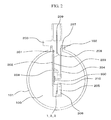
- FIG. 2 is a diagram of the configuration in FIG. 1 as seen from the front of the configuration.
- An air flow tube (intake line structural part) 101 forming a main air flow passage (hereinafter also referred to as an intake line or simply an intake tube) 100 includes a sensor installation opening 102 formed in a part of the air flow tube 101 and through which a part of a heating resistor type mass air flow measurement device 200 is inserted.
- the heating resistor type mass air flow measurement device 200 into which a humidity sensing part 500 is integrated is installed in the air flow tube 101.
- the heating resistor type mass air flow measurement device 200 includes not only a housing structural part 201 but also a base plate 202, a cover 204 configured to protect, an electronic circuit board 203, a heating resistor 1 configured to measure mass air flow, an air temp compensation resistor 2 used to measure the mass air flow, an intake air temperature sensor 3 used on the vehicle side, a bypass air passage 205 in which the heating resistor 1, the air temp compensation resistor 2, and the like are installed, a bypass channel 206 for forming the bypass air passage 205, and a seal material 207 configured to seal the main air flow passage 101 from the exterior.
- the heating resistor 1, air temp compensation resistor 2, and intake air temperature sensor 3, each configured to sense intake mass air flow or intake air temperature, are connected to the electronic circuit board 203 via a bonding material 208. Moreover, the electronic circuit board 203 is similarly electrically connected to a connector terminal 209 via the bonding material 208 so as to receive and output data from and to an external device via the connector terminal 209.
- a humidity sensing part 500 is installed on the electronic circuit board 203 configured to drive the heating resistor type mass air flow measurement device 200.
- the housing structural part 201 includes an air induction opening 210 so as to allow the humidity sensing part 500 to directly contact intake air.
- a humidity signal sensed by the humidity sensing part 500 is transmitted to the external device using the connector terminal 209.
- the electronic circuit board 203 starts generating heat without delay.
- the resultant thermal effect propagates to the humidity sensing part 500.
- the humidity sensing part 500 can be recovered to a normal condition in a short time.
- the humidity sensing part 500 has the function of detecting relative humidity and temperature
- the resultant humidity signal can be processed and utilized as an absolute humidity to accomplish the purpose while preventing heat received from the electronic circuit board 203 from affecting measurement results.
- FIG. 3 shows an example in which the humidity sensing part 500 is mounted inside a second bypass channel 211.
- the second bypass channel 211 is installed to take in part of air flowing through the main air flow passage 100.
- the electronic circuit board 203 starts generating heat without delay.
- the resultant thermal effect propagates to the humidity sensing part 500.
- the humidity sensing part 500 can be recovered to a normal condition in a short time. This is effective for removing condensed dew in an environment in which only a small amount of air can be taken in during the cold start of the engine, when condensation is likely to occur, particularly during idling.
- the heat radiation efficiency of the electronic circuit board 203 is preferably enhanced.
- a sufficient airflow is also generated in the second bypass channel. This enables heat to be radiated from the electronic circuit board 203 through the second bypass channel 211.
- the heat radiation from the electronic circuit board 203 in combination with heat radiation from the base plate 202, enhances the heat radiation effect.
- the above-described configuration allows the device to provide both the heat generation function and the heat radiation function, which are contradictory to each other.
- FIG. 4 shows an example in which the second bypass channel 211 is rearranged.
- the second bypass channel 211 is configured to bypass the bypass air passage 205.
- the humidity sensing part 500 is mounted in the second bypass channel 211.
- a second bypass inlet 212 and a second bypass outlet 213 are open in a bypass air passage 205 in a horizontal direction with respect to the direction in which air flows through the bypass air passage 205.
- This configuration allows contaminants such as dust and oil which float in the intake air not to be easily taken into the second bypass channel 211 with the humidity sensing part 500 mounted therein. Thus, the possible contamination of the humidity sensing part 500 can be avoided.
- FIG. 5 shows an example in which the second bypass channel 211 is shaped to enhance the effect of heating the humidity sensing part 500.
- the second bypass channel 211 is configured such that when the flow velocity Ub of air flowing through the bypass air passage 205 is compared with the flow velocity Usb of air flowing through the second bypass channel 211, a "Ub > Usb" relationship is established.
- the second bypass inlet 212 and the second bypass outlet 213 are open in the bypass air passage 205 in the horizontal direction with respect to the direction in which air flows through the bypass air passage 205.
- This configuration suppresses heat radiation from the electronic circuit board 203 due to the air flowing through the second bypass channel 211.
- This enables an increase in the quantity of heat applied to the periphery of the humidity sensing part 500, thus allowing a "radiated heat ⁇ received heat" tendency to be enhanced. This is an advantageous solution for a situation in which removal of condensed dew from around the humidity sensing part 500 is given top priority.
- FIG. 6 is a sectional view taken along line A-A in FIG. 5 .
- the second bypass channel 211 is constructed as follows: the electronic circuit board 203 is fixed on the base plate 202 by adhesion or the like, and the base plate 202 is assembled with a housing structural part 201 and a bypass channel 206 by adhesion or the like. A part of a wall forming the cross section of the second bypass channel 211 is formed using the electronic circuit board 203. Thus, air flowing through the second bypass channel 211 directly contacts the surfaces of the humidity sensing part 500 and the electronic circuit board 203.
- FIG. 7 shows an example corresponding to the structure in FIG. 6 in which the base plate 202 is composed of two types of materials.
- the base plate 202 is composed of a metal material and a resin material.
- the metal material is used in a drive circuit side of the heating resistor type mass air flow measurement device 200 which involves a large quantity of self-heating.
- the resin material is used in areas in which the humidity sensing part 500 and the second bypass channel 211 are installed. Heat generated on the drive circuit side of the heating resistor type mass air flow measurement device 200 is radiated, from the metal material side, to the air flowing through the main air flow passage 100. The thermal effect is also transmitted from the drive circuit side of the heating resistor type mass air flow measurement device 200 through the electronic circuit substrate 203, and reaches the periphery of the humidity sensing part 500.
- the corresponding part of the base plate 202 is composed of the resin material, the radiation of the heat to the air is suppressed.
- This configuration enables the condensation in the humidity sensing part 500 to be recovered to normal environment in a short time.
- the configuration is advantageous if in connection with the balance between the heat radiation and the heating of the humidity sensing part 500, higher emphasis is placed on the heating.
- the velocity of air flowing through the bypass air passage 205 and the second bypass channel 211 also increases as the velocity of air flowing through the main air flow passage 100 increases.
- heat is expected to be radiated from the circuit board through the second bypass channel 211.
- efficient heat radiation can be achieved.
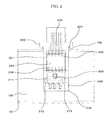
- FIG. 8 shows an example in which the present invention is applied to a configuration in which a heating resistor type mass air flow measurement device 200, an intake air temperature sensor 3, and a humidity sensing part 500 as well as a pressure sensing part 600 are integrated together.
- An air flow tube (intake line structural part) 101 included in a main air flow passage (hereinafter also referred to as an intake line or simply an intake tube) 100 includes a sensor installation opening 102 formed in a part of the air flow tube 101 and through which a part of the heating resistor type mass air flow measurement device 200 is inserted.
- the heating resistor type mass air flow measurement device 200 into which the humidity sensing part 500 is integrated is installed in the air flow tube 101.
- the heating resistor type mass air flow measurement device 200 includes not only a housing structural part 201 but also a base plate 202, a cover 204 configured to protect an electronic circuit board 203, a heating resistor 1 to measure mass air flow, an air temp compensation resistor 2 used to measure the mass air flow, the intake air temperature sensor 3 used at a vehicle side, a bypass air passage 205 in which the heating resistor 1, the air temp compensation resistor 2, and the like are installed, a bypass channel 206 forming the bypass air passage 205, and a seal material 207 to seal the main air flow passage 101 from the exterior.
- the pressure sensing part 600 is mounted on a part of the housing structural part 201 positioned outside the air flow tube 101. The pressure sensing part 600 measures the pressure inside the main air flow passage 100 via a pressure intake hole 601 formed in the housing structural part 201.
- the heating resistor 1, air temp compensation resistor 2, and intake air temperature sensor 3 which are configured to sense intake mass air flow or intake air temperature are connected to the electronic circuit board 203 via a bonding material 208. Moreover, the electronic circuit board 203 is similarly electrically connected to a connector terminal 209 via the bonding material 208 so as to receive and output data from and to an external device via the connector terminal 209.
- the humidity sensing part 500 is electrically connected to the connector terminal 209 from the electronic circuit board 203 via the bonding material 208 so as to receive and output data from and to the external device via the connector terminal 209.
- the pressure sensing part 600 receives and outputs data to and from the external device via pressure measurement I/O terminals 602 and the connector terminal 209 by, for example, welding.
- the humidity sensing part 500 is installed on the electronic circuit board 203 configured to drive the heating resistor type mass air flow measurement device 200, and is further mounted in the second bypass channel 211.
- the second bypass channel 211 is configured to bypass the bypass air passage 205.
- a second bypass inlet 212 and a second bypass outlet 213 are open in the bypass air passage 205 in the horizontal direction with respect to the direction in which air flows through the bypass air passage 205.
- a part of a wall forming the cross section of the second bypass channel 211 is formed using the electronic circuit board 203. Thus, air flowing through the second bypass channel 211 directly contacts the surfaces of the humidity sensing part 500 and the electronic circuit board 203.
- the base plate 202 is composed of a metal material and a resin material.
- the metal material is used on a drive circuit side of the heating resistor type mass air flow measurement device 200 which involves a large quantity of self-heating.
- the resin material is used in areas in which the humidity sensing part 500 and the second bypass channel 211 are installed. Heat generated on the drive circuit side of the heating resistor type mass air flow measurement device 200 is radiated, from the metal material side, to the air flowing through the main air flow passage 100. The thermal effect is also transmitted from the drive circuit side of the heating resistor type mass air flow measurement device 200 through the electronic circuit substrate 203, and reaches the periphery of the humidity sensing part 500. Then, since the corresponding part of the base plate 202 is composed of the resin material, the radiation of the heat to the air is suppressed.
- the above-described configuration allows the heating resistor type mass air flow measurement device 200, the intake air temperature sensor 3, the pressure sensing part 600, and the humidity sensing part 500 to be integrated together.
- the resultant structure is unsusceptible to condensation and excellent in heat radiation from the electronic components, particularly in connection with humidity sensing.
- Intake air 51 is sucked through an air cleaner 50 passes through a flow tube mass air flow sensor installed 52 into which the heating resistor type mass air flow measurement device 200 is inserted, an intake air duct 53, a throttle body 54, and an intake manifold 56 with an injector 55 to which fuel is supplied, and then enters an engine cylinder 57.
- exhaust gas 58 generated in the engine cylinder 57 is discharged via an exhaust manifold 59.
- a control unit 64 receives a mass air flow signal, a humidity signal, a pressure signal, and a temperature signal output by an integrated bypass channel type mass air flow sensor module 60 of the heating resistor type mass air flow measurement device 200, a throttle valve angle signal output by a throttle angle sensor 61, an oxygen concentration signal output by an oxygen meter 62 provided in the exhaust manifold 59, an engine rotation speed signal output by an engine speed meter 63, and the like.
- the control unit 64 sequentially calculates these signals to determine the optimum fuel injection amount and idle air control valve opening degree. The control unit 64 then uses these values to control the injector 55 and an idle air control valve 65.
Landscapes
- Engineering & Computer Science (AREA)
- Physics & Mathematics (AREA)
- Fluid Mechanics (AREA)
- General Physics & Mathematics (AREA)
- Chemical & Material Sciences (AREA)
- Combustion & Propulsion (AREA)
- Mechanical Engineering (AREA)
- General Engineering & Computer Science (AREA)
- Measuring Volume Flow (AREA)
Abstract
Description
- The present invention relates to a sensor integrated structure suitable for physical quantity measurements relating to intake air in an internal combustion engine, and an internal combustion engine control device that uses the sensor integrated structure.
- A heating resistor type mass air flow measurement device is known as a flow measuring technique for internal combustion engines (see
JP Patent No. 3523022 - In connection with a sensor including a flow measurement device, a pressure sensing device, a humidity sensing device, and the like for internal combustion engines which are integrated together, the sensor being capable of measuring a plurality of physical quantities,
JP Patent Publication (Kokai) No. 2008-304232A - In recent years, cars that use an electronically-controlled fuel injection system have been common. In this case, an engine room is internally crammed with various sensors and control devices. Furthermore, in that case a wire harness that interconnects various sensors and control devices as well as a control unit configured to control the sensors and control instruments is complicatedly intricate.
- Thus, there has been a demand to reduce the number of components and improve the appearance of the interior of the engine room by integrating the plurality of sensors and control instruments together. For example, in a certain measure, the above-described heating resistor type mass air flow measurement device is integrated with a temperature sensing device and even a semiconductor pressure sensing device, a humidity sensing device, and the like to allow connectors to be shared. This enables a reduction in the number of steps required to assemble components together into a vehicle and simplification of the wire harness.
- In conventionally mainstream structures, the heating resistor type mass air flow measurement device is integrated with a temperature sensing device. However, as heating resistor type mass air flow measurement devices are integrated with the above-described pressure sensing device and humidity sensing device in the future, various technical problems are expected to occur.
- In particular, the humidity sensing device described above has not been utilized for fuel control applications yet but has mainly been used to control air conditioning in the vehicle interior. Applications to the vehicle interior involve no demand for high durability based on an envisioned harsh environment. However, when integrated with, for example, the heating resistor type mass air flow measurement device or other sensors in order to control the engine, the humidity sensing device needs to offer environment resistance equivalent to that of the heating resistor type mass air flow measurement device. An environment particularly unfavorable to the humidity sensing device is condensation in a sensing element part thereof. Thus, a definite technical solution to this problem is essential.
- For example, if condensation occurs in the humidity sensing element, the humidity sensing element may output a signal value indicative of the maximum or minimum humidity depending on the configuration of the sensor or a peripheral circuit therefor, temporarily preventing the humidity sensing device from fulfilling its functions as a humidity sensing device until the sensing element part is dried. In this case, during the period in which the humidity sensing device is prevented from fulfilling its functions, the engine control system may be affected. On the other hand, the multiplexed sensor may disadvantageously increase the total current consumption of the sensor.
- An object of the present invention is to provide a sensor structure suitable for integration of the humidity sensing device and even the pressure sensing device with the mass air flow measurement device.
- To deal with the above-described problem, the present inventors have focused on the heat generation and radiation structure of the sensor itself in the mass air flow measurement device, which consumes the largest amount of current among the integrated sensors. A power transistor or the like which controls the quantity of heat applied to the mass air flow sensing element generates a large quantity of heat. If heat is not efficiently radiated from the power transistor, the temperature of the device as a whole increases. Then, electronic components and resistors with different temperature characteristics may contribute to reducing the accuracy at which the mass air flow is detected. This thermal effect may further affect, for example, the durability of the electronic components. Accordingly, an efficient heat radiation structure for the mass air flow measurement device has been sought. Thus, a base plate on which an electronic circuit board is adhesively held is preferably composed of metal. This configuration enables heat radiation based on the transfer of heat from the base plate to air flowing through a main air flow passage.
- On the other hand, the humidity sensing device needs to deal with the above-described condensation. The humidity sensing device requires, for example, means for drying the humidity sensing element subjected to condensation in a short time and means for keeping the surface of the humidity sensing element dry in wet air. To achieve this, the humidity sensing element itself may be maintained at high temperature. It is effective to heat the humidity sensing element part and the periphery thereof and to store heat in the humidity sensing element part and the periphery thereof.
- The heat radiation function and the heating function, which are contradictory to each other, are achieved by one device.
- A possible condensation environment corresponds to the cold start of an engine in a time zone from night till morning when the temperature is low. Hence, it is important to remove condensed dew in an environment in which the mass air flow in an intake tube is very low during engine start, particularly during idling. To achieve this, the humility sensing element is mounted on the electronic circuit board in the mass air flow measurement device with the temperature thereof starting to increase immediately after the sensor has been actuated. This facilitates an increase of the temperature of the humidity sensing element immediately after the sensor has been actuated.
- The humidity sensing element and a part of the circuit board surrounding the humidity sensing element are exposed to air flowing through a second bypass channel and thus radiate a slight quantity of heat. However, an intended idle flow rate offers a low flow velocity, and a "received heat > radiated heat" relationship is thus established in the humidity sensing element part. This effect is higher when the relationship between the flow velocity of air flowing through a bypass air passage and the flow velocity of air flowing through the second bypass channel is such that the flow velocity in the bypass air passage is greater than the flow velocity in the second bypass channel.
- Furthermore, to facilitate heating of the humidity sensing element, the base plate is composed of two types of materials, resin and metal. The material of the base plate holding an area where the electronic circuit board generates a large quantity of heat is composed of the metal. A part of the base plate holding the periphery of the second bypass channel, which is to be heated, is composed of the resin. This further facilitates heating of the humidity sensing element.
- In contrast, in an environment in which the sensors are unlikely to be affected by condensation, at least a given amount of air flows through the humidity sensing element part. This corresponds to, for example, an operational environment in which the flow rate in the intake tube reaches a medium or high flow rate zone. In this case, condensed dew does not need to be removed but heat radiation from the electronic circuit board is preferably enhanced. In this operational environment, a sufficient airflow is generated in the second bypass channel, enabling heat to be radiated from the electronic circuit board through the second bypass channel part. Accordingly, the heat radiation effect of the electronic circuit board, in combination with heat radiation effect from the base plate is enhanced.
- The above-described configuration allows the device to provide both the heat generation function and the heat radiation function, which are contradictory to each other.
- Heat generated by the mass air flow measurement device is effectively utilized to remove condensed dew in the humidity sensing part. This eliminates the need to additionally provide a heater function around the humidity sensing part. Alternatively, condensed dew can be removed without the use of the heater function of the humidity sensing element. This enables accurate sensing of the humidity and a reduction in the total power consumption of the sensor.
- Moreover, the improved efficiency of heat radiation, which is a capability contradictory to heat generation, serves to suppress the self-heating of the sensor, thus improving the durability of electronic components. This also reduces the adverse effects of the temperature characteristics of the electronic components or print resistors, thereby enabling other physical quantities to be accurately measured.
- According to the present invention, the vehicle can be provided, over a long period, with accurate fuel control that is essential for dealing with both exhaust gas and fuel consumption regulations.
-
-
FIG. 1 is a diagram of a sensor structure showing an embodiment of the present invention. -
FIG. 2 is a diagram of the sensor structure inFIG. 1 as seen from the front of the structure. -
FIG. 3 is a diagram of a sensor structure showing another embodiment of the present invention. -
FIG. 4 is a diagram of a sensor structure showing yet another embodiment of the present invention. -
FIG. 5 is a diagram of a sensor structure showing still another embodiment of the present invention. -
FIG. 6 is a sectional view taken along line A-A inFIG. 4 . -
FIG. 7 is a diagram of a sensor structure showing further another embodiment of the present invention. -
FIG. 8 is a diagram of a sensor structure showing further another embodiment of the present invention. -
FIG. 9 is a schematic diagram of the system configuration of an internal combustion engine in which the present invention is used. -
- 1
- Heating resistor
- 2
- Air temp compensation resistor
- 3
- Intake air temperature sensor
- 50
- Air cleaner
- 51
- Intake air
- 52
- Flow tube mass air flow sensor installed
- 53
- Intake air duct
- 54
- Throttle body
- 55
- Fuel injector
- 56
- Intake manifold
- 57
- Engine cylinder
- 58
- Exhaust gas
- 59
- Exhaust manifold
- 60
- Integrated bypass channel type mass air flow sensor module
- 61
- Throttle angle sensor
- 62
- Oxygen meter
- 63
- Engine speed meter
- 64
- Engine control unit
- 65
- Idle air control valve
- 100
- Main air flow passage
- 101
- Air flow tube
- 102
- Sensor installation opening
- 200
- Heating resistor type mass air flow measurement device
- 201
- Housing structural part
- 202
- Base plate
- 203
- Electronic circuit board
- 204
- Cover
- 205
- Bypass air passage
- 206
- Bypass channel
- 207
- Seal material
- 208
- Bonding material
- 209
- Connector terminal
- 210
- Air induction opening
- 211
- Second bypass channel
- 212
- Second bypass inlet
- 213
- Second bypass outlet
- 500
- Humidity sensing part
- 600
- Pressure sensing part
- 601
- Pressure intake hole
- 602
- Pressure measurement I/O terminals
- A specific example of a configuration according to the present invention will be described with reference to
FIG. 1 .FIG. 2 is a diagram of the configuration inFIG. 1 as seen from the front of the configuration. - An air flow tube (intake line structural part) 101 forming a main air flow passage (hereinafter also referred to as an intake line or simply an intake tube) 100 includes a
sensor installation opening 102 formed in a part of theair flow tube 101 and through which a part of a heating resistor type mass airflow measurement device 200 is inserted. The heating resistor type mass airflow measurement device 200 into which ahumidity sensing part 500 is integrated is installed in theair flow tube 101. - The heating resistor type mass air
flow measurement device 200 includes not only a housingstructural part 201 but also abase plate 202, acover 204 configured to protect, anelectronic circuit board 203, aheating resistor 1 configured to measure mass air flow, an airtemp compensation resistor 2 used to measure the mass air flow, an intakeair temperature sensor 3 used on the vehicle side, abypass air passage 205 in which theheating resistor 1, the airtemp compensation resistor 2, and the like are installed, abypass channel 206 for forming thebypass air passage 205, and aseal material 207 configured to seal the mainair flow passage 101 from the exterior. Theheating resistor 1, airtemp compensation resistor 2, and intakeair temperature sensor 3, each configured to sense intake mass air flow or intake air temperature, are connected to theelectronic circuit board 203 via abonding material 208. Moreover, theelectronic circuit board 203 is similarly electrically connected to aconnector terminal 209 via thebonding material 208 so as to receive and output data from and to an external device via theconnector terminal 209. - A
humidity sensing part 500 is installed on theelectronic circuit board 203 configured to drive the heating resistor type mass airflow measurement device 200. The housingstructural part 201 includes anair induction opening 210 so as to allow thehumidity sensing part 500 to directly contact intake air. A humidity signal sensed by thehumidity sensing part 500 is transmitted to the external device using theconnector terminal 209. - In this configuration, when the heating resistor type mass air
flow measurement device 200 is actuated, theelectronic circuit board 203 starts generating heat without delay. The resultant thermal effect propagates to thehumidity sensing part 500. As a result, even if thehumidity sensing part 500 has disadvantageously been subjected to condensation at the time of the actuation thereof, thehumidity sensing part 500 can be recovered to a normal condition in a short time. - Furthermore, for example, provided that the
humidity sensing part 500 has the function of detecting relative humidity and temperature, the resultant humidity signal can be processed and utilized as an absolute humidity to accomplish the purpose while preventing heat received from theelectronic circuit board 203 from affecting measurement results. -
FIG. 3 shows an example in which thehumidity sensing part 500 is mounted inside asecond bypass channel 211. - In this configuration, besides the
bypass air passage 205 used for the heating resistor type mass airflow measurement device 200, thesecond bypass channel 211 is installed to take in part of air flowing through the mainair flow passage 100. - In this configuration, when the heating resistor type mass air
flow measurement device 200 is actuated, theelectronic circuit board 203 starts generating heat without delay. The resultant thermal effect propagates to thehumidity sensing part 500. As a result, even if thehumidity sensing part 500 has disadvantageously been subjected to condensation at the time of the actuation thereof, thehumidity sensing part 500 can be recovered to a normal condition in a short time. This is effective for removing condensed dew in an environment in which only a small amount of air can be taken in during the cold start of the engine, when condensation is likely to occur, particularly during idling. - In contrast, in an environment in which the sensor is unlikely to be affected by condensation, the heat radiation efficiency of the
electronic circuit board 203 is preferably enhanced. Thus, in the present configuration, in a high flow rate zone in which theelectronic circuit board 203 generates the largest quantity of heat, a sufficient airflow is also generated in the second bypass channel. This enables heat to be radiated from theelectronic circuit board 203 through thesecond bypass channel 211. The heat radiation from theelectronic circuit board 203, in combination with heat radiation from thebase plate 202, enhances the heat radiation effect. The above-described configuration allows the device to provide both the heat generation function and the heat radiation function, which are contradictory to each other. -
FIG. 4 shows an example in which thesecond bypass channel 211 is rearranged. - The
second bypass channel 211 is configured to bypass thebypass air passage 205. Thehumidity sensing part 500 is mounted in thesecond bypass channel 211. Asecond bypass inlet 212 and asecond bypass outlet 213 are open in abypass air passage 205 in a horizontal direction with respect to the direction in which air flows through thebypass air passage 205. This configuration allows contaminants such as dust and oil which float in the intake air not to be easily taken into thesecond bypass channel 211 with thehumidity sensing part 500 mounted therein. Thus, the possible contamination of thehumidity sensing part 500 can be avoided. -
FIG. 5 shows an example in which thesecond bypass channel 211 is shaped to enhance the effect of heating thehumidity sensing part 500. - The
second bypass channel 211 is configured such that when the flow velocity Ub of air flowing through thebypass air passage 205 is compared with the flow velocity Usb of air flowing through thesecond bypass channel 211, a "Ub > Usb" relationship is established. In the present example, thesecond bypass inlet 212 and thesecond bypass outlet 213 are open in thebypass air passage 205 in the horizontal direction with respect to the direction in which air flows through thebypass air passage 205. This configuration suppresses heat radiation from theelectronic circuit board 203 due to the air flowing through thesecond bypass channel 211. This enables an increase in the quantity of heat applied to the periphery of thehumidity sensing part 500, thus allowing a "radiated heat < received heat" tendency to be enhanced. This is an advantageous solution for a situation in which removal of condensed dew from around thehumidity sensing part 500 is given top priority. -
FIG. 6 is a sectional view taken along line A-A inFIG. 5 . - The
second bypass channel 211 is constructed as follows: theelectronic circuit board 203 is fixed on thebase plate 202 by adhesion or the like, and thebase plate 202 is assembled with a housingstructural part 201 and abypass channel 206 by adhesion or the like. A part of a wall forming the cross section of thesecond bypass channel 211 is formed using theelectronic circuit board 203. Thus, air flowing through thesecond bypass channel 211 directly contacts the surfaces of thehumidity sensing part 500 and theelectronic circuit board 203. -
FIG. 7 shows an example corresponding to the structure inFIG. 6 in which thebase plate 202 is composed of two types of materials. - The
base plate 202 is composed of a metal material and a resin material. The metal material is used in a drive circuit side of the heating resistor type mass airflow measurement device 200 which involves a large quantity of self-heating. The resin material is used in areas in which thehumidity sensing part 500 and thesecond bypass channel 211 are installed. Heat generated on the drive circuit side of the heating resistor type mass airflow measurement device 200 is radiated, from the metal material side, to the air flowing through the mainair flow passage 100. The thermal effect is also transmitted from the drive circuit side of the heating resistor type mass airflow measurement device 200 through theelectronic circuit substrate 203, and reaches the periphery of thehumidity sensing part 500. Then, since the corresponding part of thebase plate 202 is composed of the resin material, the radiation of the heat to the air is suppressed. This configuration enables the condensation in thehumidity sensing part 500 to be recovered to normal environment in a short time. The configuration is advantageous if in connection with the balance between the heat radiation and the heating of thehumidity sensing part 500, higher emphasis is placed on the heating. - However, even in this configuration, the velocity of air flowing through the
bypass air passage 205 and thesecond bypass channel 211 also increases as the velocity of air flowing through the mainair flow passage 100 increases. Thus, at a high flow velocity at which condensation is unlikely to occur, heat is expected to be radiated from the circuit board through thesecond bypass channel 211. At a high flow rate, efficient heat radiation can be achieved. -
FIG. 8 shows an example in which the present invention is applied to a configuration in which a heating resistor type mass airflow measurement device 200, an intakeair temperature sensor 3, and ahumidity sensing part 500 as well as apressure sensing part 600 are integrated together. - An air flow tube (intake line structural part) 101 included in a main air flow passage (hereinafter also referred to as an intake line or simply an intake tube) 100 includes a
sensor installation opening 102 formed in a part of theair flow tube 101 and through which a part of the heating resistor type mass airflow measurement device 200 is inserted. The heating resistor type mass airflow measurement device 200 into which thehumidity sensing part 500 is integrated is installed in theair flow tube 101. - The heating resistor type mass air
flow measurement device 200 includes not only a housingstructural part 201 but also abase plate 202, acover 204 configured to protect anelectronic circuit board 203, aheating resistor 1 to measure mass air flow, an airtemp compensation resistor 2 used to measure the mass air flow, the intakeair temperature sensor 3 used at a vehicle side, abypass air passage 205 in which theheating resistor 1, the airtemp compensation resistor 2, and the like are installed, abypass channel 206 forming thebypass air passage 205, and aseal material 207 to seal the mainair flow passage 101 from the exterior. Moreover, thepressure sensing part 600 is mounted on a part of the housingstructural part 201 positioned outside theair flow tube 101. Thepressure sensing part 600 measures the pressure inside the mainair flow passage 100 via apressure intake hole 601 formed in the housingstructural part 201. - The
heating resistor 1, airtemp compensation resistor 2, and intakeair temperature sensor 3 which are configured to sense intake mass air flow or intake air temperature are connected to theelectronic circuit board 203 via abonding material 208. Moreover, theelectronic circuit board 203 is similarly electrically connected to aconnector terminal 209 via thebonding material 208 so as to receive and output data from and to an external device via theconnector terminal 209. - The
humidity sensing part 500 is electrically connected to theconnector terminal 209 from theelectronic circuit board 203 via thebonding material 208 so as to receive and output data from and to the external device via theconnector terminal 209. - The
pressure sensing part 600 receives and outputs data to and from the external device via pressure measurement I/O terminals 602 and theconnector terminal 209 by, for example, welding. - The
humidity sensing part 500 is installed on theelectronic circuit board 203 configured to drive the heating resistor type mass airflow measurement device 200, and is further mounted in thesecond bypass channel 211. Thesecond bypass channel 211 is configured to bypass thebypass air passage 205. Asecond bypass inlet 212 and asecond bypass outlet 213 are open in thebypass air passage 205 in the horizontal direction with respect to the direction in which air flows through thebypass air passage 205. Furthermore, a part of a wall forming the cross section of thesecond bypass channel 211 is formed using theelectronic circuit board 203. Thus, air flowing through thesecond bypass channel 211 directly contacts the surfaces of thehumidity sensing part 500 and theelectronic circuit board 203. - Moreover, the
base plate 202 is composed of a metal material and a resin material. The metal material is used on a drive circuit side of the heating resistor type mass airflow measurement device 200 which involves a large quantity of self-heating. The resin material is used in areas in which thehumidity sensing part 500 and thesecond bypass channel 211 are installed. Heat generated on the drive circuit side of the heating resistor type mass airflow measurement device 200 is radiated, from the metal material side, to the air flowing through the mainair flow passage 100. The thermal effect is also transmitted from the drive circuit side of the heating resistor type mass airflow measurement device 200 through theelectronic circuit substrate 203, and reaches the periphery of thehumidity sensing part 500. Then, since the corresponding part of thebase plate 202 is composed of the resin material, the radiation of the heat to the air is suppressed. - The above-described configuration allows the heating resistor type mass air
flow measurement device 200, the intakeair temperature sensor 3, thepressure sensing part 600, and thehumidity sensing part 500 to be integrated together. The resultant structure is unsusceptible to condensation and excellent in heat radiation from the electronic components, particularly in connection with humidity sensing. - Finally, an example in which the article of the present invention is applied to an internal combustion engine based on an electronic fuel injection system will be described with reference to
FIG. 9 -
Intake air 51 is sucked through anair cleaner 50 passes through a flow tube mass air flow sensor installed 52 into which the heating resistor type mass airflow measurement device 200 is inserted, anintake air duct 53, athrottle body 54, and anintake manifold 56 with aninjector 55 to which fuel is supplied, and then enters anengine cylinder 57. On the other hand,exhaust gas 58 generated in theengine cylinder 57 is discharged via anexhaust manifold 59. - A
control unit 64 receives a mass air flow signal, a humidity signal, a pressure signal, and a temperature signal output by an integrated bypass channel type mass airflow sensor module 60 of the heating resistor type mass airflow measurement device 200, a throttle valve angle signal output by athrottle angle sensor 61, an oxygen concentration signal output by anoxygen meter 62 provided in theexhaust manifold 59, an engine rotation speed signal output by anengine speed meter 63, and the like. Thecontrol unit 64 sequentially calculates these signals to determine the optimum fuel injection amount and idle air control valve opening degree. Thecontrol unit 64 then uses these values to control theinjector 55 and an idleair control valve 65. - Features, components and specific details of the structures of the above-described embodiments may be exchanged or combined to form further embodiments optimized for the respective application. As far as those modifications are apparent for an expert skilled in the art they shall be disclosed implicitly by the above description without specifying explicitly every possible combination.
Claims (10)
- A sensor structure in a mass air flow measurement device configured to measure intake mass air flow in an intake tube (101) and integrated with a humidity sensing device configured to detect humidity in the intake tube (101), the mass air flow measurement device (200) comprising a mass air flow sensing element (1, 2) configured to detect the intake mass air flow and mounted inside a bypass air passage (205) through which part of air flowing through the intake tube (101) is taken in,
wherein a humidity sensing element (500) and a drive circuit part of the humidity sensing element are mounted on an electronic circuit board (203) in the mass air flow measurement device (200), and the humidity sensing element directly contacts part of the intake air. - The sensor structure according to claim 1, wherein the humidity sensing element directly contacts the intake air in a second bypass channel (211) different from the bypass air passage.
- The sensor structure according to claim 2, wherein the second bypass channel is installed so as to bypass a part of the bypass air passage (205) in which the mass air flow sensing element (1, 2) is installed.
- The sensor structure according to claim 2 or 3, wherein a relationship between the velocity of air flowing through the bypass air passage (205) and the velocity of air flowing through the second bypass channel (211) is such that the flow velocity in the bypass air passage (205) is greater than the flow velocity in the second bypass channel (211).
- The sensor structure according to at least one of claims 2 to 4, wherein one surface of the electronic circuit board (203) in the mass air flow measurement device (200) also serves as a part of a wall surface forming the second bypass channel (211).
- The sensor structure according to claim 5, wherein the electronic circuit board forming the part of the wall surface of the second bypass channel (211) is adhered to and held on a base plate (202).
- The sensor structure according to claim 6, wherein the base plate comprises at least two types of materials.
- The sensor structure according to claim 7, wherein the base plate comprises a combination of materials such as resin and metal in which the thermal conductivity of one of the materials is at least 20 times as high as the thermal conductivity of the other material.
- The sensor structure according to claim 7 or 8, wherein a part of the base plate located at the position where the second bypass channel (211) is installed comprises resin, and a part of the base plate (202) located at the position where the electronic circuit board (203) in the mass air flow measurement device (200) is mainly arranged comprises metal.
- The sensor structure according to at least one of claims 1 to 9, further comprising a pressure sensing part configured to detect a pressure inside the intake tube (101).
Applications Claiming Priority (1)
| Application Number | Priority Date | Filing Date | Title |
|---|---|---|---|
| JP2009225932A JP4929333B2 (en) | 2009-09-30 | 2009-09-30 | Sensor structure |
Publications (2)
| Publication Number | Publication Date |
|---|---|
| EP2306161A1 true EP2306161A1 (en) | 2011-04-06 |
| EP2306161B1 EP2306161B1 (en) | 2016-06-29 |
Family
ID=43466649
Family Applications (1)
| Application Number | Title | Priority Date | Filing Date |
|---|---|---|---|
| EP10166382.1A Active EP2306161B1 (en) | 2009-09-30 | 2010-06-17 | Flow rate sensor structure |
Country Status (3)
| Country | Link |
|---|---|
| US (1) | US8215160B2 (en) |
| EP (1) | EP2306161B1 (en) |
| JP (1) | JP4929333B2 (en) |
Cited By (3)
| Publication number | Priority date | Publication date | Assignee | Title |
|---|---|---|---|---|
| EP3064906A4 (en) * | 2013-10-31 | 2017-03-08 | Hitachi Automotive Systems, Ltd. | Airflow measurement device |
| WO2017059985A1 (en) * | 2015-10-08 | 2017-04-13 | Robert Bosch Gmbh | Sensor device for detecting at least one flow property of a fluid medium |
| EP3176546A4 (en) * | 2014-07-30 | 2017-12-13 | Hitachi Automotive Systems, Ltd. | Physical-quantity detection device |
Families Citing this family (36)
| Publication number | Priority date | Publication date | Assignee | Title |
|---|---|---|---|---|
| JP5178388B2 (en) * | 2008-08-11 | 2013-04-10 | 日立オートモティブシステムズ株式会社 | Air flow measurement device |
| JP2012052809A (en) * | 2010-08-31 | 2012-03-15 | Hitachi Automotive Systems Ltd | Sensor structure |
| JP2012083119A (en) * | 2010-10-07 | 2012-04-26 | Hitachi Automotive Systems Ltd | Sensor structure |
| JP5396410B2 (en) * | 2011-02-09 | 2014-01-22 | 日立オートモティブシステムズ株式会社 | Sensor structure |
| JP5652315B2 (en) * | 2011-04-28 | 2015-01-14 | オムロン株式会社 | Flow measuring device |
| JP5445535B2 (en) * | 2011-08-09 | 2014-03-19 | 株式会社デンソー | Air flow measurement device |
| JP5609827B2 (en) * | 2011-09-07 | 2014-10-22 | 株式会社デンソー | Air flow measurement device |
| JP5477358B2 (en) * | 2011-10-31 | 2014-04-23 | 株式会社デンソー | Air flow measurement device |
| JP5662382B2 (en) * | 2012-06-15 | 2015-01-28 | 日立オートモティブシステムズ株式会社 | Thermal flow meter |
| JP5675717B2 (en) * | 2012-06-29 | 2015-02-25 | 日立オートモティブシステムズ株式会社 | Air physical quantity detector |
| JP6035582B2 (en) * | 2013-10-30 | 2016-11-30 | 株式会社デンソー | Air flow measurement device and method for manufacturing the same |
| JP6208251B2 (en) * | 2013-11-07 | 2017-10-04 | 日立オートモティブシステムズ株式会社 | Physical quantity measuring device |
| DE102013226138A1 (en) * | 2013-12-17 | 2015-06-18 | Robert Bosch Gmbh | Pressure sensor device, air mass measuring device, air mass measuring system and pressure measuring method |
| EP3176545B1 (en) * | 2014-07-30 | 2020-09-16 | Hitachi Automotive Systems, Ltd. | Physical-quantity detection device |
| JP5826355B1 (en) * | 2014-10-03 | 2015-12-02 | 三菱電機株式会社 | Flow measuring device |
| JP6686276B2 (en) * | 2014-12-09 | 2020-04-22 | 株式会社デンソー | Air flow meter |
| US11079262B2 (en) | 2015-01-30 | 2021-08-03 | Hitachi Automotive Systems, Ltd. | Physical quantity detection apparatus and electronic apparatus |
| FR3040213B1 (en) * | 2015-08-18 | 2017-09-15 | Continental Automotive France | METHOD FOR MANUFACTURING A MEASURING SENSOR FOR A MOTOR VEHICLE |
| FR3040214B1 (en) * | 2015-08-18 | 2017-09-15 | Continental Automotive France | MEASURING SENSOR WITH ELECTRIC COMPONENT SUPPORT FOR A MOTOR VEHICLE |
| JP6641789B2 (en) | 2015-08-27 | 2020-02-05 | 株式会社デンソー | Air flow measurement device |
| EP3358314B1 (en) * | 2015-09-30 | 2021-05-12 | Hitachi Automotive Systems, Ltd. | Physical quantity detection device |
| JP6932640B2 (en) * | 2015-09-30 | 2021-09-08 | 日立Astemo株式会社 | Physical quantity detector |
| JP6009640B1 (en) * | 2015-10-29 | 2016-10-19 | 三菱電機株式会社 | Flow measuring device |
| US10900426B2 (en) * | 2016-01-27 | 2021-01-26 | Hitachi Automotive Systems, Ltd. | Control device |
| GB2554352A (en) * | 2016-09-26 | 2018-04-04 | Stratec Biomedical Ag | Injector manifold |
| JP6565867B2 (en) | 2016-10-28 | 2019-08-28 | 株式会社デンソー | Air physical quantity sensor |
| JP6919176B2 (en) * | 2016-10-28 | 2021-08-18 | 株式会社デンソー | Air physical quantity sensor |
| JP6766620B2 (en) * | 2016-12-02 | 2020-10-14 | 株式会社デンソー | Physical quantity measuring device, abnormality detection device, and abnormality detection method |
| CN107271191B (en) * | 2017-06-29 | 2019-02-22 | 奇瑞汽车股份有限公司 | Engine Heat Balance test method |
| DE102017216656A1 (en) * | 2017-09-20 | 2019-03-21 | Robert Bosch Gmbh | Method and device for controlling a heating element of a sensor element of an air mass sensor for a vehicle and air mass sensor system for a vehicle |
| JP6855590B2 (en) * | 2017-09-29 | 2021-04-07 | 日立Astemo株式会社 | Physical quantity detector |
| JP6454809B2 (en) * | 2018-05-09 | 2019-01-16 | 日立オートモティブシステムズ株式会社 | Thermal flow meter |
| US10697815B2 (en) | 2018-06-09 | 2020-06-30 | Honeywell International Inc. | System and methods for mitigating condensation in a sensor module |
| JP6561192B2 (en) * | 2018-12-14 | 2019-08-14 | 日立オートモティブシステムズ株式会社 | Thermal flow meter |
| JP6603003B2 (en) * | 2019-07-19 | 2019-11-06 | 日立オートモティブシステムズ株式会社 | Thermal flow meter |
| JP2021039026A (en) * | 2019-09-04 | 2021-03-11 | 株式会社デンソー | Air flow measuring device |
Citations (6)
| Publication number | Priority date | Publication date | Assignee | Title |
|---|---|---|---|---|
| JPH10197305A (en) * | 1997-01-16 | 1998-07-31 | Hitachi Ltd | Thermal air flow meter and measuring element for thermal air flow meter |
| EP1128168A2 (en) * | 2000-02-23 | 2001-08-29 | Hitachi, Ltd. | Measurement apparatus for measuring physical quantity such as fluid flow |
| JP3523022B2 (en) | 1997-06-26 | 2004-04-26 | 株式会社日立製作所 | Heating resistor type air flow measuring device, intake system of internal combustion engine and control system of internal combustion engine |
| US20080163683A1 (en) * | 2007-01-04 | 2008-07-10 | Honeywell International Inc. | Packaging methods and systems for measuring multiple measurands including bi-directional flow |
| JP2008304232A (en) | 2007-06-06 | 2008-12-18 | Hitachi Ltd | Intake air flow measuring apparatus |
| EP2154494A1 (en) * | 2008-08-11 | 2010-02-17 | Hitachi Automotive Systems Ltd. | Mass air flow measurement device |
Family Cites Families (4)
| Publication number | Priority date | Publication date | Assignee | Title |
|---|---|---|---|---|
| JP2807496B2 (en) * | 1989-08-11 | 1998-10-08 | シャープ株式会社 | Active matrix substrate |
| JPH102772A (en) * | 1996-06-14 | 1998-01-06 | Hitachi Ltd | Air flow measurement device |
| DE19750496A1 (en) * | 1997-11-14 | 1999-05-20 | Bosch Gmbh Robert | Method of determining the air induced into an internal combustion engine |
| JP4882732B2 (en) * | 2006-12-22 | 2012-02-22 | 株式会社デンソー | Semiconductor device |
-
2009
- 2009-09-30 JP JP2009225932A patent/JP4929333B2/en active Active
-
2010
- 2010-06-17 EP EP10166382.1A patent/EP2306161B1/en active Active
- 2010-06-29 US US12/826,061 patent/US8215160B2/en not_active Expired - Fee Related
Patent Citations (6)
| Publication number | Priority date | Publication date | Assignee | Title |
|---|---|---|---|---|
| JPH10197305A (en) * | 1997-01-16 | 1998-07-31 | Hitachi Ltd | Thermal air flow meter and measuring element for thermal air flow meter |
| JP3523022B2 (en) | 1997-06-26 | 2004-04-26 | 株式会社日立製作所 | Heating resistor type air flow measuring device, intake system of internal combustion engine and control system of internal combustion engine |
| EP1128168A2 (en) * | 2000-02-23 | 2001-08-29 | Hitachi, Ltd. | Measurement apparatus for measuring physical quantity such as fluid flow |
| US20080163683A1 (en) * | 2007-01-04 | 2008-07-10 | Honeywell International Inc. | Packaging methods and systems for measuring multiple measurands including bi-directional flow |
| JP2008304232A (en) | 2007-06-06 | 2008-12-18 | Hitachi Ltd | Intake air flow measuring apparatus |
| EP2154494A1 (en) * | 2008-08-11 | 2010-02-17 | Hitachi Automotive Systems Ltd. | Mass air flow measurement device |
Cited By (5)
| Publication number | Priority date | Publication date | Assignee | Title |
|---|---|---|---|---|
| EP3064906A4 (en) * | 2013-10-31 | 2017-03-08 | Hitachi Automotive Systems, Ltd. | Airflow measurement device |
| EP3176546A4 (en) * | 2014-07-30 | 2017-12-13 | Hitachi Automotive Systems, Ltd. | Physical-quantity detection device |
| US10190898B2 (en) | 2014-07-30 | 2019-01-29 | Hitachi Automotive Systems, Ltd. | Physical-quantity detection device |
| WO2017059985A1 (en) * | 2015-10-08 | 2017-04-13 | Robert Bosch Gmbh | Sensor device for detecting at least one flow property of a fluid medium |
| US11162830B2 (en) | 2015-10-08 | 2021-11-02 | Robert Bosch Gmbh | Sensor device for detecting at least one flow property of a fluid medium |
Also Published As
| Publication number | Publication date |
|---|---|
| JP4929333B2 (en) | 2012-05-09 |
| US20110072894A1 (en) | 2011-03-31 |
| EP2306161B1 (en) | 2016-06-29 |
| US8215160B2 (en) | 2012-07-10 |
| JP2011075357A (en) | 2011-04-14 |
Similar Documents
| Publication | Publication Date | Title |
|---|---|---|
| US8215160B2 (en) | Sensor structure | |
| US8701475B2 (en) | Air flow measuring device | |
| US8549901B2 (en) | Sensor structure | |
| EP2012097B1 (en) | Intake air mass flow measurement device | |
| EP3012599B1 (en) | Physical quantity measuring apparatus | |
| CN101650204B (en) | Mass air flow measurement device | |
| US20070089503A1 (en) | Thermal airflow meter | |
| JP6641789B2 (en) | Air flow measurement device | |
| JP6186244B2 (en) | Temperature control device for heater for temperature and humidity sensor | |
| JP2001311637A (en) | Flow measurement device, physical detection device and engine system | |
| JP2010101885A (en) | Mass flow rate sensor device | |
| EP1742025B1 (en) | Thermal type flow measuring apparatus | |
| JP5018526B2 (en) | Flow meter signal processing system | |
| JP5634698B2 (en) | Mass flow sensor device manufacturing method and mass flow sensor device | |
| US20200158546A1 (en) | Sensor for detecting at least one property of a fluid medium | |
| US6571623B1 (en) | Measuring instrument with rectangular flow channel and sensors for measuring the mass of a flowing medium | |
| JP3378833B2 (en) | Heating resistor type air flow measurement device | |
| JP6699511B2 (en) | Humidity measuring device | |
| JP4914226B2 (en) | Gas flow meter | |
| JP2003262546A (en) | Flow measuring device and flow rate measuring method | |
| JP2003161652A (en) | Flow measurement device |
Legal Events
| Date | Code | Title | Description |
|---|---|---|---|
| PUAI | Public reference made under article 153(3) epc to a published international application that has entered the european phase |
Free format text: ORIGINAL CODE: 0009012 |
|
| 17P | Request for examination filed |
Effective date: 20100917 |
|
| AK | Designated contracting states |
Kind code of ref document: A1 Designated state(s): AL AT BE BG CH CY CZ DE DK EE ES FI FR GB GR HR HU IE IS IT LI LT LU LV MC MK MT NL NO PL PT RO SE SI SK SM TR |
|
| AX | Request for extension of the european patent |
Extension state: BA ME RS |
|
| 17Q | First examination report despatched |
Effective date: 20150728 |
|
| GRAP | Despatch of communication of intention to grant a patent |
Free format text: ORIGINAL CODE: EPIDOSNIGR1 |
|
| INTG | Intention to grant announced |
Effective date: 20160202 |
|
| RIN1 | Information on inventor provided before grant (corrected) |
Inventor name: YOGO, TAKAYUKI Inventor name: SAITO, TAKAYUKI Inventor name: KOBAYASHI, CHIHIRO |
|
| GRAS | Grant fee paid |
Free format text: ORIGINAL CODE: EPIDOSNIGR3 |
|
| GRAA | (expected) grant |
Free format text: ORIGINAL CODE: 0009210 |
|
| AK | Designated contracting states |
Kind code of ref document: B1 Designated state(s): AL AT BE BG CH CY CZ DE DK EE ES FI FR GB GR HR HU IE IS IT LI LT LU LV MC MK MT NL NO PL PT RO SE SI SK SM TR |
|
| REG | Reference to a national code |
Ref country code: GB Ref legal event code: FG4D |
|
| REG | Reference to a national code |
Ref country code: CH Ref legal event code: EP |
|
| REG | Reference to a national code |
Ref country code: AT Ref legal event code: REF Ref document number: 809473 Country of ref document: AT Kind code of ref document: T Effective date: 20160715 |
|
| REG | Reference to a national code |
Ref country code: IE Ref legal event code: FG4D |
|
| REG | Reference to a national code |
Ref country code: DE Ref legal event code: R096 Ref document number: 602010034248 Country of ref document: DE |
|
| REG | Reference to a national code |
Ref country code: LT Ref legal event code: MG4D |
|
| PG25 | Lapsed in a contracting state [announced via postgrant information from national office to epo] |
Ref country code: NO Free format text: LAPSE BECAUSE OF FAILURE TO SUBMIT A TRANSLATION OF THE DESCRIPTION OR TO PAY THE FEE WITHIN THE PRESCRIBED TIME-LIMIT Effective date: 20160929 Ref country code: LT Free format text: LAPSE BECAUSE OF FAILURE TO SUBMIT A TRANSLATION OF THE DESCRIPTION OR TO PAY THE FEE WITHIN THE PRESCRIBED TIME-LIMIT Effective date: 20160629 Ref country code: FI Free format text: LAPSE BECAUSE OF FAILURE TO SUBMIT A TRANSLATION OF THE DESCRIPTION OR TO PAY THE FEE WITHIN THE PRESCRIBED TIME-LIMIT Effective date: 20160629 |
|
| REG | Reference to a national code |
Ref country code: NL Ref legal event code: MP Effective date: 20160629 |
|
| PG25 | Lapsed in a contracting state [announced via postgrant information from national office to epo] |
Ref country code: HR Free format text: LAPSE BECAUSE OF FAILURE TO SUBMIT A TRANSLATION OF THE DESCRIPTION OR TO PAY THE FEE WITHIN THE PRESCRIBED TIME-LIMIT Effective date: 20160629 Ref country code: GR Free format text: LAPSE BECAUSE OF FAILURE TO SUBMIT A TRANSLATION OF THE DESCRIPTION OR TO PAY THE FEE WITHIN THE PRESCRIBED TIME-LIMIT Effective date: 20160930 Ref country code: LV Free format text: LAPSE BECAUSE OF FAILURE TO SUBMIT A TRANSLATION OF THE DESCRIPTION OR TO PAY THE FEE WITHIN THE PRESCRIBED TIME-LIMIT Effective date: 20160629 Ref country code: SE Free format text: LAPSE BECAUSE OF FAILURE TO SUBMIT A TRANSLATION OF THE DESCRIPTION OR TO PAY THE FEE WITHIN THE PRESCRIBED TIME-LIMIT Effective date: 20160629 Ref country code: NL Free format text: LAPSE BECAUSE OF FAILURE TO SUBMIT A TRANSLATION OF THE DESCRIPTION OR TO PAY THE FEE WITHIN THE PRESCRIBED TIME-LIMIT Effective date: 20160629 |
|
| REG | Reference to a national code |
Ref country code: AT Ref legal event code: MK05 Ref document number: 809473 Country of ref document: AT Kind code of ref document: T Effective date: 20160629 |
|
| PG25 | Lapsed in a contracting state [announced via postgrant information from national office to epo] |
Ref country code: IS Free format text: LAPSE BECAUSE OF FAILURE TO SUBMIT A TRANSLATION OF THE DESCRIPTION OR TO PAY THE FEE WITHIN THE PRESCRIBED TIME-LIMIT Effective date: 20161029 Ref country code: IT Free format text: LAPSE BECAUSE OF FAILURE TO SUBMIT A TRANSLATION OF THE DESCRIPTION OR TO PAY THE FEE WITHIN THE PRESCRIBED TIME-LIMIT Effective date: 20160629 Ref country code: RO Free format text: LAPSE BECAUSE OF FAILURE TO SUBMIT A TRANSLATION OF THE DESCRIPTION OR TO PAY THE FEE WITHIN THE PRESCRIBED TIME-LIMIT Effective date: 20160629 Ref country code: EE Free format text: LAPSE BECAUSE OF FAILURE TO SUBMIT A TRANSLATION OF THE DESCRIPTION OR TO PAY THE FEE WITHIN THE PRESCRIBED TIME-LIMIT Effective date: 20160629 Ref country code: SK Free format text: LAPSE BECAUSE OF FAILURE TO SUBMIT A TRANSLATION OF THE DESCRIPTION OR TO PAY THE FEE WITHIN THE PRESCRIBED TIME-LIMIT Effective date: 20160629 Ref country code: CZ Free format text: LAPSE BECAUSE OF FAILURE TO SUBMIT A TRANSLATION OF THE DESCRIPTION OR TO PAY THE FEE WITHIN THE PRESCRIBED TIME-LIMIT Effective date: 20160629 |
|
| PG25 | Lapsed in a contracting state [announced via postgrant information from national office to epo] |
Ref country code: BE Free format text: LAPSE BECAUSE OF FAILURE TO SUBMIT A TRANSLATION OF THE DESCRIPTION OR TO PAY THE FEE WITHIN THE PRESCRIBED TIME-LIMIT Effective date: 20160629 Ref country code: ES Free format text: LAPSE BECAUSE OF FAILURE TO SUBMIT A TRANSLATION OF THE DESCRIPTION OR TO PAY THE FEE WITHIN THE PRESCRIBED TIME-LIMIT Effective date: 20160629 Ref country code: PT Free format text: LAPSE BECAUSE OF FAILURE TO SUBMIT A TRANSLATION OF THE DESCRIPTION OR TO PAY THE FEE WITHIN THE PRESCRIBED TIME-LIMIT Effective date: 20161031 Ref country code: PL Free format text: LAPSE BECAUSE OF FAILURE TO SUBMIT A TRANSLATION OF THE DESCRIPTION OR TO PAY THE FEE WITHIN THE PRESCRIBED TIME-LIMIT Effective date: 20160629 Ref country code: AT Free format text: LAPSE BECAUSE OF FAILURE TO SUBMIT A TRANSLATION OF THE DESCRIPTION OR TO PAY THE FEE WITHIN THE PRESCRIBED TIME-LIMIT Effective date: 20160629 Ref country code: SM Free format text: LAPSE BECAUSE OF FAILURE TO SUBMIT A TRANSLATION OF THE DESCRIPTION OR TO PAY THE FEE WITHIN THE PRESCRIBED TIME-LIMIT Effective date: 20160629 |
|
| REG | Reference to a national code |
Ref country code: DE Ref legal event code: R097 Ref document number: 602010034248 Country of ref document: DE |
|
| PLBE | No opposition filed within time limit |
Free format text: ORIGINAL CODE: 0009261 |
|
| STAA | Information on the status of an ep patent application or granted ep patent |
Free format text: STATUS: NO OPPOSITION FILED WITHIN TIME LIMIT |
|
| PG25 | Lapsed in a contracting state [announced via postgrant information from national office to epo] |
Ref country code: DK Free format text: LAPSE BECAUSE OF FAILURE TO SUBMIT A TRANSLATION OF THE DESCRIPTION OR TO PAY THE FEE WITHIN THE PRESCRIBED TIME-LIMIT Effective date: 20160629 |
|
| 26N | No opposition filed |
Effective date: 20170330 |
|
| PG25 | Lapsed in a contracting state [announced via postgrant information from national office to epo] |
Ref country code: SI Free format text: LAPSE BECAUSE OF FAILURE TO SUBMIT A TRANSLATION OF THE DESCRIPTION OR TO PAY THE FEE WITHIN THE PRESCRIBED TIME-LIMIT Effective date: 20160629 Ref country code: BG Free format text: LAPSE BECAUSE OF FAILURE TO SUBMIT A TRANSLATION OF THE DESCRIPTION OR TO PAY THE FEE WITHIN THE PRESCRIBED TIME-LIMIT Effective date: 20160929 |
|
| PG25 | Lapsed in a contracting state [announced via postgrant information from national office to epo] |
Ref country code: MC Free format text: LAPSE BECAUSE OF FAILURE TO SUBMIT A TRANSLATION OF THE DESCRIPTION OR TO PAY THE FEE WITHIN THE PRESCRIBED TIME-LIMIT Effective date: 20160629 |
|
| REG | Reference to a national code |
Ref country code: CH Ref legal event code: PL |
|
| GBPC | Gb: european patent ceased through non-payment of renewal fee |
Effective date: 20170617 |
|
| REG | Reference to a national code |
Ref country code: IE Ref legal event code: MM4A |
|
| REG | Reference to a national code |
Ref country code: FR Ref legal event code: ST Effective date: 20180228 |
|
| PG25 | Lapsed in a contracting state [announced via postgrant information from national office to epo] |
Ref country code: LI Free format text: LAPSE BECAUSE OF NON-PAYMENT OF DUE FEES Effective date: 20170630 Ref country code: CH Free format text: LAPSE BECAUSE OF NON-PAYMENT OF DUE FEES Effective date: 20170630 Ref country code: GB Free format text: LAPSE BECAUSE OF NON-PAYMENT OF DUE FEES Effective date: 20170617 Ref country code: LU Free format text: LAPSE BECAUSE OF NON-PAYMENT OF DUE FEES Effective date: 20170617 Ref country code: IE Free format text: LAPSE BECAUSE OF NON-PAYMENT OF DUE FEES Effective date: 20170617 |
|
| PG25 | Lapsed in a contracting state [announced via postgrant information from national office to epo] |
Ref country code: FR Free format text: LAPSE BECAUSE OF NON-PAYMENT OF DUE FEES Effective date: 20170630 |
|
| PG25 | Lapsed in a contracting state [announced via postgrant information from national office to epo] |
Ref country code: MT Free format text: LAPSE BECAUSE OF NON-PAYMENT OF DUE FEES Effective date: 20170617 |
|
| PG25 | Lapsed in a contracting state [announced via postgrant information from national office to epo] |
Ref country code: AL Free format text: LAPSE BECAUSE OF FAILURE TO SUBMIT A TRANSLATION OF THE DESCRIPTION OR TO PAY THE FEE WITHIN THE PRESCRIBED TIME-LIMIT Effective date: 20160629 |
|
| PG25 | Lapsed in a contracting state [announced via postgrant information from national office to epo] |
Ref country code: HU Free format text: LAPSE BECAUSE OF FAILURE TO SUBMIT A TRANSLATION OF THE DESCRIPTION OR TO PAY THE FEE WITHIN THE PRESCRIBED TIME-LIMIT; INVALID AB INITIO Effective date: 20100617 |
|
| PG25 | Lapsed in a contracting state [announced via postgrant information from national office to epo] |
Ref country code: CY Free format text: LAPSE BECAUSE OF NON-PAYMENT OF DUE FEES Effective date: 20160629 |
|
| PG25 | Lapsed in a contracting state [announced via postgrant information from national office to epo] |
Ref country code: MK Free format text: LAPSE BECAUSE OF FAILURE TO SUBMIT A TRANSLATION OF THE DESCRIPTION OR TO PAY THE FEE WITHIN THE PRESCRIBED TIME-LIMIT Effective date: 20160629 |
|
| PG25 | Lapsed in a contracting state [announced via postgrant information from national office to epo] |
Ref country code: TR Free format text: LAPSE BECAUSE OF FAILURE TO SUBMIT A TRANSLATION OF THE DESCRIPTION OR TO PAY THE FEE WITHIN THE PRESCRIBED TIME-LIMIT Effective date: 20160629 |
|
| REG | Reference to a national code |
Ref country code: DE Ref legal event code: R082 Ref document number: 602010034248 Country of ref document: DE Representative=s name: MERH-IP MATIAS ERNY REICHL HOFFMANN PATENTANWA, DE Ref country code: DE Ref legal event code: R081 Ref document number: 602010034248 Country of ref document: DE Owner name: HITACHI ASTEMO, LTD., HITACHINAKA-SHI, JP Free format text: FORMER OWNER: HITACHI AUTOMOTIVE SYSTEMS, LTD., HITACHINAKA-SHI, IBARAKI, JP |
|
| PGFP | Annual fee paid to national office [announced via postgrant information from national office to epo] |
Ref country code: DE Payment date: 20250429 Year of fee payment: 16 |