EP2310246B1 - Pillar structure of vehicle and method for manufacturing the same - Google Patents
Pillar structure of vehicle and method for manufacturing the same Download PDFInfo
- Publication number
- EP2310246B1 EP2310246B1 EP09785979.7A EP09785979A EP2310246B1 EP 2310246 B1 EP2310246 B1 EP 2310246B1 EP 09785979 A EP09785979 A EP 09785979A EP 2310246 B1 EP2310246 B1 EP 2310246B1
- Authority
- EP
- European Patent Office
- Prior art keywords
- weak portion
- portions
- weak
- pillar structure
- reinforcement member
- Prior art date
- Legal status (The legal status is an assumption and is not a legal conclusion. Google has not performed a legal analysis and makes no representation as to the accuracy of the status listed.)
- Active
Links
Images











Classifications
-
- B—PERFORMING OPERATIONS; TRANSPORTING
- B62—LAND VEHICLES FOR TRAVELLING OTHERWISE THAN ON RAILS
- B62D—MOTOR VEHICLES; TRAILERS
- B62D25/00—Superstructure or monocoque structure sub-units; Parts or details thereof not otherwise provided for
- B62D25/04—Door pillars ; windshield pillars
-
- B—PERFORMING OPERATIONS; TRANSPORTING
- B62—LAND VEHICLES FOR TRAVELLING OTHERWISE THAN ON RAILS
- B62D—MOTOR VEHICLES; TRAILERS
- B62D21/00—Understructures, i.e. chassis frame on which a vehicle body may be mounted
- B62D21/15—Understructures, i.e. chassis frame on which a vehicle body may be mounted having impact absorbing means, e.g. a frame designed to permanently or temporarily change shape or dimension upon impact with another body
- B62D21/157—Understructures, i.e. chassis frame on which a vehicle body may be mounted having impact absorbing means, e.g. a frame designed to permanently or temporarily change shape or dimension upon impact with another body for side impacts
-
- B—PERFORMING OPERATIONS; TRANSPORTING
- B62—LAND VEHICLES FOR TRAVELLING OTHERWISE THAN ON RAILS
- B62D—MOTOR VEHICLES; TRAILERS
- B62D25/00—Superstructure or monocoque structure sub-units; Parts or details thereof not otherwise provided for
- B62D25/02—Side panels
- B62D25/025—Side sills thereof
-
- Y—GENERAL TAGGING OF NEW TECHNOLOGICAL DEVELOPMENTS; GENERAL TAGGING OF CROSS-SECTIONAL TECHNOLOGIES SPANNING OVER SEVERAL SECTIONS OF THE IPC; TECHNICAL SUBJECTS COVERED BY FORMER USPC CROSS-REFERENCE ART COLLECTIONS [XRACs] AND DIGESTS
- Y10—TECHNICAL SUBJECTS COVERED BY FORMER USPC
- Y10T—TECHNICAL SUBJECTS COVERED BY FORMER US CLASSIFICATION
- Y10T29/00—Metal working
- Y10T29/49—Method of mechanical manufacture
- Y10T29/49616—Structural member making
- Y10T29/49622—Vehicular structural member making
Definitions
- the invention relates to a pillar structure applied to a vehicle, such as an automobile, and a method for manufacturing the pillar structure.
- JP-A-10-17933 describes a pillar structure for preventing a local deformation of a pillar when a vehicle is hit on the side.
- a reinforcement member of the pillar is quenched to have a strength distribution similar to an impact load distribution.
- a pillar structure according to the preamble of claim 1 is known from US 2005/023862 A1 and a method according to the preamble of claim 22 is known from EP 1 457 576 A .
- the above object is solved with a pillar structure having the features of claim 1 and a method having the features of claim 22.
- the pillar structure of a vehicle according to the present invention includes: a pillar that includes a first weak portion and a second weak portion, wherein the second weak portion is located above the first weak portion.
- the pillar bends at least at two portions, that is, the first weak portion and the second weak portion, so it is possible to reduce the bending moment generated in the pillar.
- the pillar structure it is possible to control deformation of the pillar in the event of a side collision while ensuring the strength of the pillar.
- the pillar may have a protrusion, that protrudes outward from the pillar in a vehicle width direction, between the first weak portion and the second weak portion.
- the strength of the first weak portion is lower than the strength of the second weak portion.
- the first weak portion may be located below an acting portion at which external force is assumed to act on the pillar from an outer side in a vehicle width direction, and the second weak portion may be located above the acting portion.
- the pillar includes an outer shell and a reinforcement member arranged in the outer shell, and the first weak portion and the second weak portion are respectively implemented by weakened portions in the reinforcement member.
- the weakened portions in the reinforcement member may be implemented by beads formed in the reinforcement member.
- a difference in strength between the first weak portion and the second weak portion may be implemented by at least any one of the size of the beads, the number of the beads, and the thickness of the reinforcement member in which the beads are formed.
- each of the weakened portions in the reinforcement member may be implemented by at least one of a bead or a harness fitting hole, which is formed in the reinforcement member.
- the reinforcement member may have portions to which a first hinge and a second hinge of a door are attached, the first hinge may be attached between the first weak portion and the second weak portion, and the second hinge may be attached above the second weak portion.
- the ratio of a distance between the second weak portion and the first hinge to a distance between the first weak portion and the first hinge may range from 1:1 to 2:1.
- At least one of the first hinge and the second hinge may project in a vehicle width direction of the vehicle.
- an end portion of a door beam may be arranged in correspondence with at least one of the first weak portion and the second weak portion.
- At least one of the first weak portion and the second weak portion may include a load input member that facilitate a load to be input to the at least one of the first weak portion and the second weak portion when external force acts on the vehicle from an outer side in a vehicle width direction.
- a shock-absorbing member may be attached between the first weak portion and the second weak portion.
- the pillar may be configured so that, when external force acts on a portion between the first weak portion and the second weak portion from an outer side in a vehicle width direction, a displacement of the portion between the first weak portion and the second weak portion is maximal.
- the pillar may include an outer shell and a reinforcement member arranged in the outer shell, and the reinforcement member may have non-quenched portions formed at an upper portion and a lower portion with respect to a portion to which a lower hinge of a door is attached, and quenched portions formed at portions other than the upper portion and the lower portion, wherein the first weak portion and the second weak portion may be implemented by the non-quenched portions.
- the reinforcement member has the non-quenched portions formed at the upper portion and the lower portion with respect to the portion to which the lower hinge is attached, so it is possible to easily and reliably provide the pillar with the first weak portion and the second weak portion. Then, when the vehicle is hit on the side, the reinforcement member bends at the upper and lower portions with respect to the portion to which the lower hinge is attached, so it is possible to reduce the bending moment generated in the reinforcement member.
- the pillar may include an outer shell and a reinforcement member arranged in the outer shell, and the first weak portion and the second weak portion may be implemented by non-quenched portions.
- non-quenched portions may be formed in the reinforcement member to project toward the outer shell.
- the reinforcement member may be manufactured in such a manner that, when the reinforcement member is quenched, flow of cooling water to portions of the heated reinforcement member, corresponding to the quenched portions, is increased as compared with flow of cooling water to portions of the heated reinforcement member, corresponding to the non-quenched portions.
- the quenching densities of the portions of the reinforcement member, corresponding to the non-quenched portions are lower than the quenching densities of the portions of the reinforcement member, corresponding to the quenched portions, so it is possible to reliably form the non-quenched portions at the upper portion and the lower portion of the reinforcement member with respect to the portion to which the lower hinge of the door is attached.
- the reinforcement member may be manufactured in such a manner that the portions corresponding to the non-quenched portions are formed to project, gaps between a hot stamping die and the portions corresponding to the non-quenched portions are narrower than gaps between the die and the portions corresponding to the quenched portions and then flow of the cooling water to the portions corresponding to the quenched portions is increased as compared with flow of the cooling water to the portions corresponding to the non-quenched portions.
- the reinforcement member may be manufactured in such a manner that cooling water supply holes are formed in a hot stamping die in correspondence with the quenched portions, cooling water drain holes are formed in the die in correspondence with boundaries between the quenched portions and the non-quenched portions and then flow of the cooling water to the portions corresponding to the quenched portions is increased as compared with flow of the cooling water to the portions corresponding to the non-quenched portions.
- the ground height of the first weak portion and the ground height of the second weak portion may be determined on the basis of a height at which external force is assumed to act on the vehicle from an outer side in a vehicle width direction.
- the ground height of the first weak portion and the ground height of the second weak portion may be determined on the basis of a bumper height of a typical vehicle.
- FIG 1 is an exploded perspective view of a center pillar structure, which is a first embodiment of the pillar structure of a vehicle according to the invention.
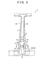
- FIG 2 is a side view of the center pillar structure shown in FIG 1 .
- the center pillar structure 1 of a vehicle such as an automobile, includes a center pillar 10.
- the center pillar 10 includes an outer panel 15, an inner panel 16, an outer reinforcement 2 and hinge reinforcements 13 and 14.
- the outer panel 15 and the inner panel 16 extend from a rocker to a roof side rail.
- the outer reinforcement 2 and the hinge reinforcements 13 and 14 are arranged in an internal space defined by the outer panel 15 and the inner panel 16.
- the outer panel 15 may be regarded as an outer shell member according to the aspect of the invention.
- the inner panel 16 may be regarded as an outer shell member according to the aspect of the invention.
- the outer reinforcement 2 may be regarded as a reinforcement member according to the aspect of the invention.
- the outer reinforcement 2 is formed so that high-tensile steel plates are jointed at a laser welding seam 3 as a boundary.
- the lower end portion of the outer reinforcement 2 is connected to the rocker, and the upper end portion of the outer reinforcement 2 is connected to the roof side rail.
- the strength of the lower high-tensile steel plate with respect to the laser welding seam 3 is lower than the strength of the upper high-tensile steel plate with respect to the laser welding seam 3 in such a manner that, for example, the thickness of the lower high-tensile steel plate is made thinner. That is, in the outer reinforcement 2, the portion on the lower side of the laser welding seam 3 is weaker than the portion on the upper side of the laser welding seam 3.
- the outer reinforcement 2 has beads 11 and 12 such that a pair of outer edge lines 2c formed by an outer wall 2a and a pair of side walls 2b are cut out.
- the beads 11 are located below the laser welding seam 3, and the beads 12 are located above the laser welding seam 3.
- the center pillar 10 has a weak portion 17 and a weak portion 18.
- the weak portion 17 is implemented by the beads 11.
- the weak portion 18 is implemented by the beads 12.
- the beads 11 and 12 may be regarded as weakened portions in the reinforcement member according to the aspect of the invention.
- the weak portion 17 may be regarded as a first weak portion according to the aspect of the invention.
- the weak portion 18 may be regarded as a second weak portion according to the aspect of the invention.
- a lower hinge 4 for a door is attached to a portion between the beads 11 and the beads 12, and an upper hinge 5 for the door is attached to a portion on the upper side of the beads 12. That is, the center pillar structure 1 includes the lower hinge 4, which is a protrusion between the weak portion 17 and the weak portion 18, and the protrusion protrudes outward from the center pillar 10 in the vehicle width direction.
- the hinge reinforcement 13 is arranged on the inner side of the outer reinforcement 2 in correspondence with a portion of the outer reinforcement 2, to which the lower hinge 4 is attached.
- the hinge reinforcement 14 is arranged on the inner side of the outer reinforcement 2 so as to extend from a portion of the outer reinforcement 2, to which the upper hinge 5 is attached, to an upper end portion of the outer reinforcement 2.
- the laser welding seam 3 is located between the portion, to which the lower hinge 4 is attached, and the beads 12; however, the laser welding seam 3 may be located between the portion, to which the lower hinge 4 is attached, and the beads 11.
- the graph with projections and depressions at the right side in FIG. 3 shows a strength distribution of the center pillar structure 1.
- the strength of the center pillar 10 is locally low at the weak portion 17 and at the weak portion 18. Therefore, when the vehicle is hit on the side, the center pillar 10 bends at the weak portion 17 and at the weak portion 18, and therefore the vehicle colliding advances substantially horizontally. This can reduce the bending moment generated in the center pillar 10 due to the advancement of the colliding vehicle, so it is possible to control deformation of the center pillar 10 in the event of a side collision while ensuring the strength of the center pillar 10.
- the strength of the center pillar 10 is varied by a large amount between the upper side and the lower side with respect to the lower end portion of the hinge reinforcement 14. This can remarkably localize a decrease in strength of the upper weak portion 18.
- the weak portion 17 and the weak portion 18 are implemented by the beads 11 and beads 12 of the outer reinforcement 2, so it is possible to easily and reliably provide the center pillar 10 with the weak portion 17 and the weak portion 18.
- the strength is minimal at the weak portion 17 and at the weak portion 18; however, the strength does not need to be minimal as long as the strength is locally low at the weak portion 17 and at the weak portion 18.
- the lower hinge 4 or an assumed load input region (acting portion at which external force is assumed to act on the center pillar 10 from the outer side in the vehicle width direction) may be located at a ground height of 400 mm to 500 mm. This is based on the bumper height of a typical vehicle. Alternatively, the lower hinge 4 or the assumed load input region may be located at a height that at least partially or entirely falls within the bumper height of the host vehicle.
- Table 1 GROUND HEIGHT (mm) MOST DESIRABLE RANGE MINIMUM MAXIMUM UPPER WEAK PORTION 18 500 TO 550 500 600 LOWER HINGE 4 OR ASSUMED LOAD INPUT REGION 400 TO 500 300 600 LOWER WEAK PORTION 17 350 TO 400 300 400
- the assumed load input region is a region in which a load acts from an object that is assumed to collide at the time of design, and may be, for example, a region corresponding to the bumper height.
- the weak portion 17 and the weak portion 18 may be located in the middle of the assumed load input region or so as to place the entire assumed load input region in between from above and below.
- the ratio of the "distance between the upper weak portion 18 and the lower hinge 4" to the "distance between the lower weak portion 17 and the lower hinge 4" may be a range from 1:1 to 2:1.
- 1:1 it is possible to reliably deform the portion between the weak portion 17 and the weak portion 18 so as to be substantially parallel to the vertical direction when the vehicle is hit on the side.
- 2:1 the bending point approaches the middle portion of the center pillar 10 without significantly losing the parallelism between the vertical direction and the portion between the weak portion 17 and the weak portion 18.
- the lower hinge 4 which is a protrusion that protrudes outward from the center pillar 10 in the vehicle width direction between the weak portion 17 and the weak portion 18, will be described.
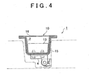
- FIG. 4 is a cross-sectional view of the center pillar structure 1, taken along the line IV-IV in FIG 2 .
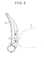
- FIG 5 is a front view of the center pillar structure 1 shown in FIG 1 .
- the lower hinge 4 protrudes outward from the center pillar 10 in the vehicle width direction between the weak portion 17 and the weak portion 18. Therefore, it is possible to easily concentrate a load on the portion between the weak portion 17 and the weak portion 18 in the initial stage of a collision with an object, such as the other vehicle V, and, as a result, it is possible to deform that portion desirably.
- the hinge reinforcement 13 is arranged on the inner side of the outer reinforcement 2 in correspondence with a portion of the outer reinforcement 2, to which the lower hinge 4 is attached. By doing so, it is possible to relatively increase the strength of the portion between the weak portion 17 and the weak portion 18 as compared with the strength of the weak portion 17 or the strength of the weak portion 18.
- the thickness of the high-tensile steel plate is, for example, varied between above and below the laser welding seam 3 to increase the weakness of the portion on the lower side of the laser welding seam 3 as compared with the portion on the upper side of the laser welding seam 3.
- the outer reinforcement 2 has the beads 11 and the beads 12. The beads 11 are located below the laser welding seam 3. The beads 12 are located above the laser welding seam 3. Thus, the strength of the weak portion 17 formed below the laser welding seam 3 is lower than the weak portion 18 formed above the laser welding seam 3.
- the strength of the lower weak portion 17 may be decreased as compared with the strength of the upper weak portion 18.
- the center pillar 10 bends at the lower weak portion 17 in the initial stage in which the other vehicle V (that is the vehicle colliding) collides with the side of the host vehicle as shown in FIG 6A , and, thereafter, the center pillar 10 bends at the upper weak portion 18 as shown in FIG 6B . Therefore, the other vehicle V advances substantially horizontally, and the portion between the weak portion 17 and the weak portion 18 deforms to be substantially parallel to the vertical direction. Thus, it is possible to reduce the bending moment generated in the center pillar 10 due to advancement of the other vehicle V.
- the strength of the upper weak portion 18 may be decreased as compared with the strength of the lower weak portion 17, or the strength of the upper weak portion 18 may be equivalent to the strength of the lower weak portion 17.
- FIG 7 is a cross-sectional view of a center pillar structure that has the load input member 19.
- FIG 8 is a perspective view of the center pillar structure that has the load input member 19.
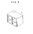
- FIG 9 is a perspective view of the load input member 19.
- the load input member 19 is arranged in a front door 31 so as to face the lower weak portion 17 in the vehicle width direction.
- the load input member 19 is, for example, made of resin and has a block shape.
- the load input member 19 is hollowed for reduction in weight.
- the strength of the load input member 19 is higher than the strength of the outer reinforcement 2, and is lower than the bonding strength between the rocker and the outer reinforcement.
- the load concentrates on the lower hinge 4 and then the load input member 19 facilitates a local load to be input to the weak portion 17.
- the center pillar 10 to initially bend at the lower weak portion 17 and subsequently bend at the upper weak portion 18.
- the other vehicle V advances substantially horizontally, and the portion between the weak portion 17 and the weak portion 18 deforms to be substantially parallel to the vertical direction.
- the load input member 19 may be arranged in correspondence with at least one of the weak portion 17 and the weak portion 18.
- the strength of the load input member 19 arranged in correspondence with the upper weak portion 18 and the strength of the load input member 19 arranged in correspondence with the lower weak portion 7 are varied to thereby making it possible to control local loads input respectively to the weak portion 17 and the weak portion 18.
- the load input member 19 may be arranged in a rear door 32.
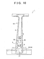
- FIG 10 is a side view of a center pillar structure that has the weak portion implemented by the harness fitting hole 35.
- FIG 11 is a cross-sectional view of the center pillar structure that has the weak portion implemented by the harness fitting hole.
- the harness fitting hole 35 is formed in the center pillar 10 between the portion to which the lower hinge 4 is attached and the portion to which the upper hinge 5 is attached.
- a harness 34 is attached to the harness fitting hole 35 and holds a wire 33 associated with a power window, a door lock, and the like. In this way, the upper weak portion 18 may be implemented by the harness fitting hole 35 instead of the beads 12.
- harness fitting hole 35 is formed on the lower side with respect to the portion of the center pillar 10, to which the lower hinge 4 is attached, and the lower weak portion 17 is implemented by the harness fitting hole 35 instead of the beads 11.
- FIG 12 is a side view of a center pillar structure that has door beams having end portions arranged in correspondence with the weak portions.
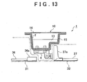
- FIG 13 is a cross-sectional view of the center pillar structure that has the door beams having the end portions arranged in correspondence with the weak portions.
- a rear end portion 36a of a front door beam 36 is arranged in the front door 31 so as to face the lower weak portion 17 in the vehicle width direction
- a front end portion 37a of a rear door beam 37 is arranged in the rear door 32 so as to face the upper weak portion 18 in the vehicle width direction.
- the door beams 36 and 37 are reinforcement members for absorbing energy when the vehicle is hit on the side.
- the load concentrates on the lower hinge 4 and then the rear end portion 36a of the front door beam 36 facilitates a local load to be input to the lower weak portion 17, while the front end portion 37a of the rear door beam 37 facilitates a local load to be input to the upper weak portion 18.
- the other vehicle V collides with the middle of the front door 31 or the middle of the rear door 37 with an offset frontward or rearward from the center pillar 10, it is possible to reliably bend the center pillar 10 at the weak portion 17 and at the weak portion 18.
- the rear end portion 36a of the front door beam 36 is arranged in correspondence with the upper weak portion 18, and the front end portion 37a of the rear door beam 37 is arranged in correspondence with the lower weak portion 17.
- the rear end portion 36a of the front door beam 36 or the front end portion 37a of the rear door beam 37 may be arranged in correspondence with at least one of the weak portion 17 and the weak portion 18.
- the rear end portion 36a of the front door beam 36 or the front end portion 37a of the rear door beam 37, which is arranged in correspondence with the lower weak portion 17, may be located at a height equivalent to that of the lower weak portion 17 or may be located in an assumed load input region that is set slightly above the lower weak portion 17.
- the portion between the weak portion 17 and the weak portion 18 deforms to be substantially parallel to the vertical direction when the vehicle is hit on the side, for example, it is possible to prevent a situation that the center pillar bends only at the portion corresponding to the lower weak portion 17 and then that portion protrudes into a cabin of the vehicle.
- the center pillar bends only at the portion corresponding to the lower weak portion 17 when the center pillar 10 bends both at the weak portion 17 and at the weak portion 18 and then the portion between the weak portion 17 and the weak portion 18 deforms to be substantially parallel to the vertical direction, it is possible to suppress a speed at which the deformed portion of the center pillar 10 is displaced.
- the center pillar 10 may be configured so that, when external force acts on the portion between the weak portion 17 and the weak portion 18 from the outside in the vehicle width direction, a displacement of the portion between the weak portion 17 and the weak portion 18 is maximal.
- the center pillar 10 may be configured so that the portion between the weak portion 17 and the weak portion 18 deforms into a curved shape having a tangent line that is substantially parallel to the vertical direction.
- shock-absorbing member 38 arranged in correspondence with the portion between the weak portion 17 and the weak portion 18 will be described.
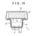
- FIG 15 is a cross-sectional view of a center pillar structure that has the shock-absorbing member 38.
- a pillar garnish 39 is attached onto the inner side (cabin side) of the center pillar 10.
- the shock-absorbing member 38 is, for example, made of urethane foam.
- the shock-absorbing member 38 is arranged in the pillar garnish 39 so as to face the portion between the weak portion 17 and the weak portion 18 in the vehicle width direction. Thus, even when the portion between the weak portion 17 and the weak portion 18 deforms into the cabin at the time when the vehicle is hit on the side, the shock may be reduced.
- shock-absorbing member 38 may be attached to a seat side surface, or the like, as long as the shock-absorbing member 38 is arranged on the inner side with respect to the center pillar 10 in correspondence with the portion between the weak portion 17 and the weak portion 18.
- FIG 16 is a perspective view of a center pillar structure, which is a second embodiment of the pillar structure of a vehicle according to the invention.
- FIG 17 is a front view of the center pillar structure shown in FIG 16 .
- the center pillar structure 1 includes an outer reinforcement 2.
- the outer reinforcement 2 is formed so that high-tensile steel plates are jointed via a laser welding seam 3.
- the upper end portion of the outer reinforcement 2 is connected to a roof side rail, and the lower end portion of the outer reinforcement 2 is connected to a rocker.
- An outward projected non-quenched portion 6 is formed in the outer reinforcement 2 between a portion to which a lower hinge 4 of a door is attached and a portion to which an upper hinge 5 of the door is attached.
- an outward projected non-quenched portion 7 is formed in the outer reinforcement 2 between the portion to which the lower hinge 4 is attached and a portion connected to the rocker.
- the non-quenched portions 6 and 7 are formed in the outer reinforcement 2 at the upper and lower portions with respect to the portion to which the lower hinge 4 is attached, while quenched portions 8 are formed in the outer reinforcement 2 at portions other than the non-quenched portions 6 and 7.
- portions corresponding to the weak portion 17 and the weak portion 18 according to the first embodiment are implemented respectively by the non-quenched portion 7 and the non-quenched portion 6.
- the center pillar structure 1 by forming the non-quenched portions 6 and 7 in the outer reinforcement 2 at the upper and lower portions with respect to the portion to which the lower hinge 4 is attached, it is possible to easily form buckling points (bending points) in the event of a side collision. Then, when the vehicle is hit on the side, the outer reinforcement 2 bends at the upper and lower portions with respect to the portion to which the lower hinge 4 is attached, so it is possible to reduce the bending moment generated in the outer reinforcement 2 due to advancement of the other vehicle. Thus, with the center pillar structure 1, it is possible to control deformation of the center pillar in the event of a side collision while ensuring the strength of the center pillar.
- FIG 18A shows an outer reinforcement 102 in which one point, that is, an upper portion with respect to the portion to which the lower hinge 4 is attached, becomes a buckling point B when the vehicle is hit on the side.
- FIG 18B shows the outer reinforcement 2 according to the second embodiment in which two points, that is, the upper and lower portions with respect to the portion to which the lower hinge 4 is attached, become buckling points B when the vehicle is hit on the side. Note that, in the outer reinforcement 2 shown in FIG. 18B , the strength of the non-quenched portion 7 is lower than the strength of the non-quenched portion 6.
- FIG 19A to FIG 19C respectively show the deformed outer reinforcement 102 shown in FIG. 18A , a bending moment diagram and shear force diagram of the deformed outer reinforcement 102 shown in FIG 18A .
- FIG 20A, FIG. 20B and FIG. 20C respectively show the deformed outer reinforcement 2 shown in FIG 18B , a bending moment diagram and shear force diagram of the deformed outer reinforcement 2 shown in FIG 18B .
- M B indicates a moment applied to the buckling point B.
- Fy indicates an impact reaction force generated by the outer reinforcement
- Fy B is a reaction force generated by bending within Fy.
- the outer reinforcement 102 generates an impact reaction force in the event of a side collision by a relatively large bending and a relatively small axial force
- the outer reinforcement 2 generates an impact reaction force in the event of a side collision by a relatively small bending and a relatively large axial force
- a moment input to a beltline portion reduces. Therefore, it is possible to reduce reinforcement at the beltline portion, and it is possible to reduce the weight and cost of the center pillar.
- a high-tensile steel plate 2a which will be the outer reinforcement 2
- the high-tensile steel plate 2a is stamped and heated with a cope (die) 21 and a drag (die) 22 for hot stamping.
- gaps between the cope 21 and drag 22 and the high-tensile steel plate 2a are appropriately controlled so that gaps between the cope 21 and portions 6a and 7a corresponding to the non-quenched portions 6 and 7 in the high-tensile steel plate 2a are narrower than gaps between the cope 21 and portions 8a corresponding to the quenched portions 8 in the high-tensile steel plate 2a.
- the cope 21 is brought into close contact with the portions 6a and 7a corresponding to the non-quenched portions 6 and 7.
- cooling water is supplied through cooling water supply holes 21a, formed in the cope 21, into the gaps between the cope 21 and the portions 8a corresponding to the quenched portions 8.
- the cope 21 is in close contact with the portions 6a and 7a corresponding to the non-quenched portions 6 and 7. Therefore, as shown in FIG. 22 , cooling water does not flow to the portions 6a and 7a corresponding to the non-quenched portions 6 and 7, and cooling water flows only to the portions 8a corresponding to the quenched portions 8.
- the thus formed outer reinforcement 2 is used to manufacture the center pillar structure 1.
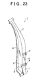
- FIG 23 is a perspective view of a center pillar structure, which is a third embodiment of the pillar structure of a vehicle according to the invention.
- the center pillar structure 1 according to the third embodiment differs from the above described center pillar structure 1 according to the second embodiment in that non-quenched portions 6 and 7 are not projected in the outer reinforcement 2.
- the center pillar structure 1 is manufactured as follows. That is, as shown in FIG. 24 and FIG 25 , a high-tensile steel plate 2a, which will be the outer reinforcement 2, is prepared, and then the high-tensile steel plate 2a is stamped and heated with a cope (die) 21 and a drag (die) 22 for hot stamping. Subsequently, cooling water is supplied through cooling water supply holes 21a into gaps between the cope 21 and the portions 8a corresponding to the quenched portions 8. The cooling water supply holes 21a are formed in the cope 21 at portions in correspondence with the quenched portions 8. The supplied cooling water is drained outside through cooling water drain holes 21b.
- the cooling water drain holes 21b are formed in the cope 21 at portions in correspondence with boundaries between the quenched portions 8 and the non-quenched portions 6 and 7. Thus, no cooling water flows to the portions 6a and 7a corresponding to the non-quenched portions 6 and 7, and cooling water flows only to the portions 8a corresponding to the quenched portions 8. Hence, only the portions 8a are quenched by rapid cooling. Then, the thus formed outer reinforcement 2 is used to manufacture the center pillar structure 1.
- a pair of outer edge line portions respectively have the beads 11 and 12.
- the number of beads 12 formed in the upper portion with respect to the portion to which the lower hinge 4 is attached is larger than the number of beads 11 formed in the lower portion with respect to the portion to which the lower hinge 4 is attached, while, on the other hand, the thickness and material are varied between the lower portion and the upper portion.
- the strength of the member of the upper portion with respect to the laser welding seam 3 is higher than the strength of the member of the lower portion with respect to the laser welding seam 3. In this case, it is not necessary to joint high-tensile steel plates at the laser welding seam 3 as a boundary in order to form the outer reinforcement 2.
- a bead 12 is formed to extend over a pair of outer edge line portions, and beads 11 are formed respectively at the pair of outer edge line portions.
- a lower end portion of the hinge reinforcement 14 that extends along the inner surface of the outer wall of the outer reinforcement 2 is elongated to the inner side of the bead 12.
- the pillar structure of a vehicle according to the aspect of the invention is not necessarily limited to a center pillar structure, and the number of weak portions of the pillar is not limited to two.
- the weak portion may be implemented not only by the shape of a member that constitutes the pillar but also by changing the material of a member that constitutes the pillar, adjusting the thickness of the material of the member, a degree to which the material of the member is quenched, the plastic effect of the material of the member, or the like.
Landscapes
- Engineering & Computer Science (AREA)
- Chemical & Material Sciences (AREA)
- Combustion & Propulsion (AREA)
- Transportation (AREA)
- Mechanical Engineering (AREA)
- Body Structure For Vehicles (AREA)
Description
- The invention relates to a pillar structure applied to a vehicle, such as an automobile, and a method for manufacturing the pillar structure.
- Japanese Patent Application Publication No.
10-17933 JP-A-10-17933 - However, in the above described pillar structure, it is extremely difficult to control deformation of a pillar in the event of a side collision while ensuring the strength of the pillar.
- Furthermore, a pillar structure according to the preamble of
claim 1 is known fromUS 2005/023862 A1 and a method according to the preamble ofclaim 22 is known fromEP 1 457 576 A - It is the object of the present invention to provide a pillar structure of a vehicle, which is able to control deformation of a pillar in the event of a side collision while ensuring the strength of the pillar, and a method for manufacturing the pillar structure.
- According to the present invention, the above object is solved with a pillar structure having the features of
claim 1 and a method having the features ofclaim 22. - The pillar structure of a vehicle according to the present invention includes: a pillar that includes a first weak portion and a second weak portion, wherein the second weak portion is located above the first weak portion.
- Thus, when the vehicle is hit on the side, the pillar bends at least at two portions, that is, the first weak portion and the second weak portion, so it is possible to reduce the bending moment generated in the pillar. Thus, with the pillar structure, it is possible to control deformation of the pillar in the event of a side collision while ensuring the strength of the pillar.
- The pillar may have a protrusion, that protrudes outward from the pillar in a vehicle width direction, between the first weak portion and the second weak portion. With the above aspect, when the vehicle is hit on the side, it is possible to concentrate external force on the portion between the first weak portion and the second weak portion, and, as a result, it is possible to deform that portion desirably.
- According to the present invention, the strength of the first weak portion is lower than the strength of the second weak portion. Thus, when the vehicle is hit on the side, it is possible to cause a portion between the first weak portion and the second weak portion to deform to be substantially parallel to a vertical direction.
- Furthermore, the first weak portion may be located below an acting portion at which external force is assumed to act on the pillar from an outer side in a vehicle width direction, and the second weak portion may be located above the acting portion. With the above aspect, when the vehicle is hit on the side, it is possible to desirably deform a portion between the first weak portion and the second weak portion.
- According to the present invention, the pillar includes an outer shell and a reinforcement member arranged in the outer shell, and the first weak portion and the second weak portion are respectively implemented by weakened portions in the reinforcement member. Thus, it is possible to easily and reliably provide the pillar with the first weak portion and the second weak portion.
- Furthermore, the weakened portions in the reinforcement member may be implemented by beads formed in the reinforcement member.
- Furthermore, a difference in strength between the first weak portion and the second weak portion may be implemented by at least any one of the size of the beads, the number of the beads, and the thickness of the reinforcement member in which the beads are formed.
- Furthermore, each of the weakened portions in the reinforcement member may be implemented by at least one of a bead or a harness fitting hole, which is formed in the reinforcement member.
- Furthermore, the reinforcement member may have portions to which a first hinge and a second hinge of a door are attached, the first hinge may be attached between the first weak portion and the second weak portion, and the second hinge may be attached above the second weak portion.
- Furthermore, the ratio of a distance between the second weak portion and the first hinge to a distance between the first weak portion and the first hinge may range from 1:1 to 2:1.
- Furthermore, at least one of the first hinge and the second hinge may project in a vehicle width direction of the vehicle.
- Furthermore, an end portion of a door beam may be arranged in correspondence with at least one of the first weak portion and the second weak portion. With the above aspect, when the vehicle is hit on the side, it is possible to cause the pillar to reliably bend at the first weak portion and at the second weak portion.
- Furthermore, at least one of the first weak portion and the second weak portion may include a load input member that facilitate a load to be input to the at least one of the first weak portion and the second weak portion when external force acts on the vehicle from an outer side in a vehicle width direction.
- Furthermore, a shock-absorbing member may be attached between the first weak portion and the second weak portion.
- Furthermore, the pillar may be configured so that, when external force acts on a portion between the first weak portion and the second weak portion from an outer side in a vehicle width direction, a displacement of the portion between the first weak portion and the second weak portion is maximal. With the above aspect, for example, it is possible to prevent a situation that the pillar bends only at a portion corresponding to the first weak portion and then that portion protrudes into a cabin of the vehicle.
- Furthermore, the pillar may include an outer shell and a reinforcement member arranged in the outer shell, and the reinforcement member may have non-quenched portions formed at an upper portion and a lower portion with respect to a portion to which a lower hinge of a door is attached, and quenched portions formed at portions other than the upper portion and the lower portion, wherein the first weak portion and the second weak portion may be implemented by the non-quenched portions. With the above aspect, the reinforcement member has the non-quenched portions formed at the upper portion and the lower portion with respect to the portion to which the lower hinge is attached, so it is possible to easily and reliably provide the pillar with the first weak portion and the second weak portion. Then, when the vehicle is hit on the side, the reinforcement member bends at the upper and lower portions with respect to the portion to which the lower hinge is attached, so it is possible to reduce the bending moment generated in the reinforcement member.
- Furthermore, the pillar may include an outer shell and a reinforcement member arranged in the outer shell, and the first weak portion and the second weak portion may be implemented by non-quenched portions.
- Furthermore, the non-quenched portions may be formed in the reinforcement member to project toward the outer shell.
- Furthermore, the reinforcement member may be manufactured in such a manner that, when the reinforcement member is quenched, flow of cooling water to portions of the heated reinforcement member, corresponding to the quenched portions, is increased as compared with flow of cooling water to portions of the heated reinforcement member, corresponding to the non-quenched portions. With the above aspect, the quenching densities of the portions of the reinforcement member, corresponding to the non-quenched portions, are lower than the quenching densities of the portions of the reinforcement member, corresponding to the quenched portions, so it is possible to reliably form the non-quenched portions at the upper portion and the lower portion of the reinforcement member with respect to the portion to which the lower hinge of the door is attached.
- Furthermore, the reinforcement member may be manufactured in such a manner that the portions corresponding to the non-quenched portions are formed to project, gaps between a hot stamping die and the portions corresponding to the non-quenched portions are narrower than gaps between the die and the portions corresponding to the quenched portions and then flow of the cooling water to the portions corresponding to the quenched portions is increased as compared with flow of the cooling water to the portions corresponding to the non-quenched portions. Alternatively, in the above aspect, the reinforcement member may be manufactured in such a manner that cooling water supply holes are formed in a hot stamping die in correspondence with the quenched portions, cooling water drain holes are formed in the die in correspondence with boundaries between the quenched portions and the non-quenched portions and then flow of the cooling water to the portions corresponding to the quenched portions is increased as compared with flow of the cooling water to the portions corresponding to the non-quenched portions. With the above two aspects, flow of cooling water to the portions of the reinforcement member, corresponding to the non-quenched portions, is suppressed, so it is possible to easily and reliably form the non-quenched portions at the upper portion and the lower portion with respect to the portion to which the lower hinge of the door is attached.
- Furthermore, the ground height of the first weak portion and the ground height of the second weak portion may be determined on the basis of a height at which external force is assumed to act on the vehicle from an outer side in a vehicle width direction.
- Furthermore, the ground height of the first weak portion and the ground height of the second weak portion may be determined on the basis of a bumper height of a typical vehicle.
- Moreover, a method for manufacturing a pillar structure that includes a pillar having an outer shell and a reinforcement member arranged in the outer shell comprises: when the reinforcement member is quenched, increasing flow of cooling water to portions of the heated reinforcement member, other than an upper portion and a lower portion with respect to a portion, to which a lower hinge of a door is attached, in the heated reinforcement member, as compared with the upper portion and the lower portion; and providing the pillar with a first weak portion and a second weak portion, which is located above the first weak portion, in such a manner that the upper portion and the lower portion are formed as non-quenched portions and the portions other than the upper portion and the lower portion are formed as quenched portions.
- Thus, it is possible to easily manufacture the above described pillar structure of a vehicle according to
claim 1. - With the pillar structure according to
claim 1 and the method according toclaim 22, it is possible to control deformation of the pillar in the event of a side collision while ensuring the strength of the pillar. - The features, advantages, and technical and industrial significance of this invention will be described in the following detailed description of example embodiments of the invention with reference to the accompanying drawings, in which like numerals denote like elements, and wherein:
-
FIG 1 is an exploded perspective view of a center pillar structure, which is a first embodiment of the pillar structure of a vehicle according to the invention; -
FIG 2 is a side view of the center pillar structure shown inFIG 1 ; -
FIG 3 is a view that shows a strength distribution of a center pillar of the center pillar structure shown inFIG 1 ; -
FIG 4 is a cross-sectional view that is taken along the line IV-IV inFIG 2 ; -
FIG 5 is a front view of the center pillar structure shown inFIG 1 ; -
FIG 6A and FIG 6B are views that show a state of deformation of the center pillar of the center pillar structure shown inFIG 1 ; -
FIG 7 is a cross-sectional view of a center pillar structure that has a load input member; -
FIG 8 is a perspective view of the center pillar structure that has the load input member; -
FIG 9 is a perspective view of the load input member; -
FIG 10 is a side view of a center pillar structure that has a weak portion implemented by a harness fitting hole; -
FIG. 11 is a cross-sectional view of the center pillar structure that has the weak portion implemented by the harness fitting hole; -
FIG 12 is a side view of a center pillar structure that has door beams having end portions arranged in correspondence with the weak portions; -
FIG 13 is a cross-sectional view of the center pillar structure that has the door beams having the end portions arranged in correspondence with the weak portions; -
FIG 14 is a view that shows a state of deformation of a center pillar that is designed so that a portion between weak portions deforms in a curved shape having a tangent line substantially parallel to a vertical direction; -
FIG 15 is a cross-sectional view of a center pillar structure that has a shock-absorbing member; -
FIG 16 is a perspective view of a center pillar structure, which is a second embodiment of the pillar structure of a vehicle according to the invention; -
FIG. 17 is a front view of the center pillar structure shown inFIG 16 ; -
FIG 18A is a view that shows a state of deformation of an outer reinforcement in the event of a side collision according to a related art; -
FIG 18B is a view that shows a state of deformation of an outer reinforcement in the event of a side collision according to the second embodiment; -
FIG 19A, FIG 19B and FIG 19C respectively show the deformed outer reinforcement shown inFIG. 18A , a bending moment diagram and shearing force diagram of the deformed outer reinforcement shown inFIG 18A ; -
FIG 20A, FIG 20B and FIG 20C respectively show the deformed outer reinforcement shown inFIG 18B , a bending moment diagram and shearing force diagram of the deformed outer reinforcement shown inFIG 18B ; -
FIG 21 is a view that shows a process of manufacturing the center pillar structure shown inFIG 16 ; -
FIG 22 is a view that shows the process of manufacturing the center pillar structure shown inFIG 16 ; -
FIG. 23 is a perspective view of a center pillar structure, which is a third embodiment of the pillar structure of a vehicle according to the invention; -
FIG. 24 is a view that shows a process of manufacturing the center pillar structure shown inFIG 23 ; -
FIG. 25 is a view that shows a process of manufacturing the center pillar structure shown inFIG 23 ; -
FIG. 26 is a perspective view of a center pillar structure, which is another embodiment of the pillar structure of a vehicle according to the invention; -
FIG 27 is a perspective view of a center pillar structure, which is another embodiment of the pillar structure of a vehicle according to the invention; and -
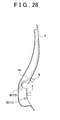
FIG 28 is a view that shows a state of deformation of an outer reinforcement shown inFIG. 27 in the event of a side collision. - Hereinafter, embodiments of the invention will be described in detail with reference to the accompanying drawings. Note that like reference numerals denote like or corresponding components in the drawings, and the overlap description is omitted.
-
FIG 1 is an exploded perspective view of a center pillar structure, which is a first embodiment of the pillar structure of a vehicle according to the invention.FIG 2 is a side view of the center pillar structure shown inFIG 1 . As shown inFIG 1 andFIG 2 , thecenter pillar structure 1 of a vehicle, such as an automobile, includes acenter pillar 10. Thecenter pillar 10 includes anouter panel 15, aninner panel 16, anouter reinforcement 2 and hingereinforcements outer panel 15 and theinner panel 16 extend from a rocker to a roof side rail. Theouter reinforcement 2 and thehinge reinforcements outer panel 15 and theinner panel 16. - The
outer panel 15 may be regarded as an outer shell member according to the aspect of the invention. Theinner panel 16 may be regarded as an outer shell member according to the aspect of the invention. Theouter reinforcement 2 may be regarded as a reinforcement member according to the aspect of the invention. - The
outer reinforcement 2 is formed so that high-tensile steel plates are jointed at alaser welding seam 3 as a boundary. The lower end portion of theouter reinforcement 2 is connected to the rocker, and the upper end portion of theouter reinforcement 2 is connected to the roof side rail. Note that the strength of the lower high-tensile steel plate with respect to thelaser welding seam 3 is lower than the strength of the upper high-tensile steel plate with respect to thelaser welding seam 3 in such a manner that, for example, the thickness of the lower high-tensile steel plate is made thinner. That is, in theouter reinforcement 2, the portion on the lower side of thelaser welding seam 3 is weaker than the portion on the upper side of thelaser welding seam 3. - The
outer reinforcement 2 hasbeads outer edge lines 2c formed by anouter wall 2a and a pair ofside walls 2b are cut out. Thebeads 11 are located below thelaser welding seam 3, and thebeads 12 are located above thelaser welding seam 3. Thus, thecenter pillar 10 has aweak portion 17 and aweak portion 18. Theweak portion 17 is implemented by thebeads 11. Theweak portion 18 is implemented by thebeads 12. - The
beads weak portion 17 may be regarded as a first weak portion according to the aspect of the invention. Theweak portion 18 may be regarded as a second weak portion according to the aspect of the invention. - In the
outer reinforcement 2, alower hinge 4 for a door is attached to a portion between thebeads 11 and thebeads 12, and anupper hinge 5 for the door is attached to a portion on the upper side of thebeads 12. That is, thecenter pillar structure 1 includes thelower hinge 4, which is a protrusion between theweak portion 17 and theweak portion 18, and the protrusion protrudes outward from thecenter pillar 10 in the vehicle width direction. - The
hinge reinforcement 13 is arranged on the inner side of theouter reinforcement 2 in correspondence with a portion of theouter reinforcement 2, to which thelower hinge 4 is attached. Thehinge reinforcement 14 is arranged on the inner side of theouter reinforcement 2 so as to extend from a portion of theouter reinforcement 2, to which theupper hinge 5 is attached, to an upper end portion of theouter reinforcement 2. Note that, here, thelaser welding seam 3 is located between the portion, to which thelower hinge 4 is attached, and thebeads 12; however, thelaser welding seam 3 may be located between the portion, to which thelower hinge 4 is attached, and thebeads 11. - The graph with projections and depressions at the right side in
FIG. 3 shows a strength distribution of thecenter pillar structure 1. In the above configuredcenter pillar structure 1, as shown inFIG. 3 , the strength of thecenter pillar 10 is locally low at theweak portion 17 and at theweak portion 18. Therefore, when the vehicle is hit on the side, thecenter pillar 10 bends at theweak portion 17 and at theweak portion 18, and therefore the vehicle colliding advances substantially horizontally. This can reduce the bending moment generated in thecenter pillar 10 due to the advancement of the colliding vehicle, so it is possible to control deformation of thecenter pillar 10 in the event of a side collision while ensuring the strength of thecenter pillar 10. - In addition, as shown in
FIG. 3 , by setting the lower end portion of thehinge reinforcement 14 near theupper beads 12, the strength of thecenter pillar 10 is varied by a large amount between the upper side and the lower side with respect to the lower end portion of thehinge reinforcement 14. This can remarkably localize a decrease in strength of the upperweak portion 18. - In addition, the
weak portion 17 and theweak portion 18 are implemented by thebeads 11 andbeads 12 of theouter reinforcement 2, so it is possible to easily and reliably provide thecenter pillar 10 with theweak portion 17 and theweak portion 18. - Note that in the strength distribution shown in
FIG 3 , the strength is minimal at theweak portion 17 and at theweak portion 18; however, the strength does not need to be minimal as long as the strength is locally low at theweak portion 17 and at theweak portion 18. - Next, a location of the
lower hinge 4, which is a protrusion that protrudes outward from thecenter pillar 10 in the vehicle width direction between theweak portion 17 and theweak portion 18, will be described. - As shown in Table 1, the
lower hinge 4 or an assumed load input region (acting portion at which external force is assumed to act on thecenter pillar 10 from the outer side in the vehicle width direction) may be located at a ground height of 400 mm to 500 mm. This is based on the bumper height of a typical vehicle. Alternatively, thelower hinge 4 or the assumed load input region may be located at a height that at least partially or entirely falls within the bumper height of the host vehicle.Table 1 GROUND HEIGHT (mm) MOST DESIRABLE RANGE MINIMUM MAXIMUM UPPER WEAK PORTION 18500 TO 550 500 600 LOWER HINGE 4 OR ASSUMED LOAD INPUT REGION400 TO 500 300 600 LOWER WEAK PORTION 17350 TO 400 300 400 - In addition, the assumed load input region is a region in which a load acts from an object that is assumed to collide at the time of design, and may be, for example, a region corresponding to the bumper height. The
weak portion 17 and theweak portion 18 may be located in the middle of the assumed load input region or so as to place the entire assumed load input region in between from above and below. - The ratio of the "distance between the upper
weak portion 18 and thelower hinge 4" to the "distance between the lowerweak portion 17 and thelower hinge 4" may be a range from 1:1 to 2:1. When the ratio is 1:1, it is possible to reliably deform the portion between theweak portion 17 and theweak portion 18 so as to be substantially parallel to the vertical direction when the vehicle is hit on the side. On the other hand, when the ratio is 2:1, the bending point approaches the middle portion of thecenter pillar 10 without significantly losing the parallelism between the vertical direction and the portion between theweak portion 17 and theweak portion 18. Thus, it is possible to further reduce the bending moment generated in thecenter pillar 10. - Next, the operations and advantages of the
lower hinge 4, which is a protrusion that protrudes outward from thecenter pillar 10 in the vehicle width direction between theweak portion 17 and theweak portion 18, will be described. -
FIG. 4 is a cross-sectional view of thecenter pillar structure 1, taken along the line IV-IV inFIG 2 .FIG 5 is a front view of thecenter pillar structure 1 shown inFIG 1 . As shown inFIG 4 andFIG 5 , thelower hinge 4 protrudes outward from thecenter pillar 10 in the vehicle width direction between theweak portion 17 and theweak portion 18. Therefore, it is possible to easily concentrate a load on the portion between theweak portion 17 and theweak portion 18 in the initial stage of a collision with an object, such as the other vehicle V, and, as a result, it is possible to deform that portion desirably. - Note that, in the case of a pillar, such as a center pillar of a slide door or a center pillar of a two-door vehicle, that is not equipped with a door hinge, by providing a protrusion, instead of the
lower hinge 4, that protrudes outward in the vehicle width direction, it is also possible to easily concentrate a load on the portion between theweak portion 17 and theweak portion 18. - In addition, the
hinge reinforcement 13 is arranged on the inner side of theouter reinforcement 2 in correspondence with a portion of theouter reinforcement 2, to which thelower hinge 4 is attached. By doing so, it is possible to relatively increase the strength of the portion between theweak portion 17 and theweak portion 18 as compared with the strength of theweak portion 17 or the strength of theweak portion 18. - Next, the relative relationship between the strength of the
weak portion 17 and the strength of theweak portion 18 will be described. - In the
outer reinforcement 2, the thickness of the high-tensile steel plate is, for example, varied between above and below thelaser welding seam 3 to increase the weakness of the portion on the lower side of thelaser welding seam 3 as compared with the portion on the upper side of thelaser welding seam 3. In addition, theouter reinforcement 2 has thebeads 11 and thebeads 12. Thebeads 11 are located below thelaser welding seam 3. Thebeads 12 are located above thelaser welding seam 3. Thus, the strength of theweak portion 17 formed below thelaser welding seam 3 is lower than theweak portion 18 formed above thelaser welding seam 3. - The strength of the lower
weak portion 17 may be decreased as compared with the strength of the upperweak portion 18. When the strength of the lowerweak portion 17 is lower than the strength of the upperweak portion 18, thecenter pillar 10 bends at the lowerweak portion 17 in the initial stage in which the other vehicle V (that is the vehicle colliding) collides with the side of the host vehicle as shown inFIG 6A , and, thereafter, thecenter pillar 10 bends at the upperweak portion 18 as shown inFIG 6B . Therefore, the other vehicle V advances substantially horizontally, and the portion between theweak portion 17 and theweak portion 18 deforms to be substantially parallel to the vertical direction. Thus, it is possible to reduce the bending moment generated in thecenter pillar 10 due to advancement of the other vehicle V. - Note that the strength of the upper
weak portion 18 may be decreased as compared with the strength of the lowerweak portion 17, or the strength of the upperweak portion 18 may be equivalent to the strength of the lowerweak portion 17. - Next, the
load input member 19 that is arranged in correspondence with theweak portion 17 will be described. -
FIG 7 is a cross-sectional view of a center pillar structure that has theload input member 19.FIG 8 is a perspective view of the center pillar structure that has theload input member 19.FIG 9 is a perspective view of theload input member 19. As shown inFIG 7 andFIG 8 , theload input member 19 is arranged in afront door 31 so as to face the lowerweak portion 17 in the vehicle width direction. As shown inFIG. 9 , theload input member 19 is, for example, made of resin and has a block shape. Theload input member 19 is hollowed for reduction in weight. The strength of theload input member 19 is higher than the strength of theouter reinforcement 2, and is lower than the bonding strength between the rocker and the outer reinforcement. - With the above configuration, in the initial stage in which the other vehicle V collides with the side, the load concentrates on the
lower hinge 4 and then theload input member 19 facilitates a local load to be input to theweak portion 17. Thus, for example, even when the strength of the lowerweak portion 17 is equivalent to the strength of the upperweak portion 18, it is possible to cause thecenter pillar 10 to initially bend at the lowerweak portion 17 and subsequently bend at the upperweak portion 18. By doing so, the other vehicle V advances substantially horizontally, and the portion between theweak portion 17 and theweak portion 18 deforms to be substantially parallel to the vertical direction. Hence, it is possible to reduce the bending moment generated in thecenter pillar 10 due to advancement of the other vehicle V. - Note that the
load input member 19 may be arranged in correspondence with at least one of theweak portion 17 and theweak portion 18. When theload input member 19 is arranged in correspondence with each of theweak portion 17 and theweak portion 18, the strength of theload input member 19 arranged in correspondence with the upperweak portion 18 and the strength of theload input member 19 arranged in correspondence with the lowerweak portion 7 are varied to thereby making it possible to control local loads input respectively to theweak portion 17 and theweak portion 18. In addition, theload input member 19 may be arranged in arear door 32. - Next, a
weak portion 18 implemented by a harnessfitting hole 35 will be described. -
FIG 10 is a side view of a center pillar structure that has the weak portion implemented by theharness fitting hole 35.FIG 11 is a cross-sectional view of the center pillar structure that has the weak portion implemented by the harness fitting hole. As shown inFIG 10 andFIG 11 , theharness fitting hole 35 is formed in thecenter pillar 10 between the portion to which thelower hinge 4 is attached and the portion to which theupper hinge 5 is attached. Aharness 34 is attached to theharness fitting hole 35 and holds awire 33 associated with a power window, a door lock, and the like. In this way, the upperweak portion 18 may be implemented by theharness fitting hole 35 instead of thebeads 12. - Note that it is also applicable that the
harness fitting hole 35 is formed on the lower side with respect to the portion of thecenter pillar 10, to which thelower hinge 4 is attached, and the lowerweak portion 17 is implemented by theharness fitting hole 35 instead of thebeads 11. - Next, door beams that have end portions arranged in correspondence with the
weak portions -
FIG 12 is a side view of a center pillar structure that has door beams having end portions arranged in correspondence with the weak portions.FIG 13 is a cross-sectional view of the center pillar structure that has the door beams having the end portions arranged in correspondence with the weak portions. As shown inFIG 12 andFIG 13 , arear end portion 36a of afront door beam 36 is arranged in thefront door 31 so as to face the lowerweak portion 17 in the vehicle width direction, and afront end portion 37a of arear door beam 37 is arranged in therear door 32 so as to face the upperweak portion 18 in the vehicle width direction. The door beams 36 and 37 are reinforcement members for absorbing energy when the vehicle is hit on the side. - With the above configuration, in the initial stage in which the other vehicle V collides with the side, the load concentrates on the
lower hinge 4 and then therear end portion 36a of thefront door beam 36 facilitates a local load to be input to the lowerweak portion 17, while thefront end portion 37a of therear door beam 37 facilitates a local load to be input to the upperweak portion 18. Thus, for example, even when the other vehicle V collides with the middle of thefront door 31 or the middle of therear door 37 with an offset frontward or rearward from thecenter pillar 10, it is possible to reliably bend thecenter pillar 10 at theweak portion 17 and at theweak portion 18. - Note that it is also applicable that the
rear end portion 36a of thefront door beam 36 is arranged in correspondence with the upperweak portion 18, and thefront end portion 37a of therear door beam 37 is arranged in correspondence with the lowerweak portion 17. In addition, therear end portion 36a of thefront door beam 36 or thefront end portion 37a of therear door beam 37 may be arranged in correspondence with at least one of theweak portion 17 and theweak portion 18. In addition, therear end portion 36a of thefront door beam 36 or thefront end portion 37a of therear door beam 37, which is arranged in correspondence with the lowerweak portion 17, may be located at a height equivalent to that of the lowerweak portion 17 or may be located in an assumed load input region that is set slightly above the lowerweak portion 17. - Next, the advantages resulting from deformation of the portion between the
weak portion 17 and theweak portion 18 to be substantially parallel to the vertical direction when the vehicle is hit on the side will be described. - As the portion between the
weak portion 17 and theweak portion 18 deforms to be substantially parallel to the vertical direction when the vehicle is hit on the side, for example, it is possible to prevent a situation that the center pillar bends only at the portion corresponding to the lowerweak portion 17 and then that portion protrudes into a cabin of the vehicle. In addition, for example, in comparison with the case where the center pillar bends only at the portion corresponding to the lowerweak portion 17, when thecenter pillar 10 bends both at theweak portion 17 and at theweak portion 18 and then the portion between theweak portion 17 and theweak portion 18 deforms to be substantially parallel to the vertical direction, it is possible to suppress a speed at which the deformed portion of thecenter pillar 10 is displaced. - Note that the
center pillar 10 may be configured so that, when external force acts on the portion between theweak portion 17 and theweak portion 18 from the outside in the vehicle width direction, a displacement of the portion between theweak portion 17 and theweak portion 18 is maximal. In addition, as shown inFIG 14 , thecenter pillar 10 may be configured so that the portion between theweak portion 17 and theweak portion 18 deforms into a curved shape having a tangent line that is substantially parallel to the vertical direction. - Next, a shock-absorbing
member 38 arranged in correspondence with the portion between theweak portion 17 and theweak portion 18 will be described. -
FIG 15 is a cross-sectional view of a center pillar structure that has the shock-absorbingmember 38. As shown inFIG 15 , apillar garnish 39 is attached onto the inner side (cabin side) of thecenter pillar 10. The shock-absorbingmember 38 is, for example, made of urethane foam. The shock-absorbingmember 38 is arranged in thepillar garnish 39 so as to face the portion between theweak portion 17 and theweak portion 18 in the vehicle width direction. Thus, even when the portion between theweak portion 17 and theweak portion 18 deforms into the cabin at the time when the vehicle is hit on the side, the shock may be reduced. - Note that the shock-absorbing
member 38 may be attached to a seat side surface, or the like, as long as the shock-absorbingmember 38 is arranged on the inner side with respect to thecenter pillar 10 in correspondence with the portion between theweak portion 17 and theweak portion 18. -
FIG 16 is a perspective view of a center pillar structure, which is a second embodiment of the pillar structure of a vehicle according to the invention.FIG 17 is a front view of the center pillar structure shown inFIG 16 . As shown inFIG 16 andFIG. 17 , thecenter pillar structure 1 includes anouter reinforcement 2. Theouter reinforcement 2 is formed so that high-tensile steel plates are jointed via alaser welding seam 3. The upper end portion of theouter reinforcement 2 is connected to a roof side rail, and the lower end portion of theouter reinforcement 2 is connected to a rocker. - An outward projected
non-quenched portion 6 is formed in theouter reinforcement 2 between a portion to which alower hinge 4 of a door is attached and a portion to which anupper hinge 5 of the door is attached. In addition, an outward projectednon-quenched portion 7 is formed in theouter reinforcement 2 between the portion to which thelower hinge 4 is attached and a portion connected to the rocker. In this way, thenon-quenched portions outer reinforcement 2 at the upper and lower portions with respect to the portion to which thelower hinge 4 is attached, while quenchedportions 8 are formed in theouter reinforcement 2 at portions other than thenon-quenched portions center pillar 10, portions corresponding to theweak portion 17 and theweak portion 18 according to the first embodiment are implemented respectively by thenon-quenched portion 7 and thenon-quenched portion 6. - As described above, with the
center pillar structure 1, by forming thenon-quenched portions outer reinforcement 2 at the upper and lower portions with respect to the portion to which thelower hinge 4 is attached, it is possible to easily form buckling points (bending points) in the event of a side collision. Then, when the vehicle is hit on the side, theouter reinforcement 2 bends at the upper and lower portions with respect to the portion to which thelower hinge 4 is attached, so it is possible to reduce the bending moment generated in theouter reinforcement 2 due to advancement of the other vehicle. Thus, with thecenter pillar structure 1, it is possible to control deformation of the center pillar in the event of a side collision while ensuring the strength of the center pillar. -
FIG 18A shows anouter reinforcement 102 in which one point, that is, an upper portion with respect to the portion to which thelower hinge 4 is attached, becomes a buckling point B when the vehicle is hit on the side.FIG 18B shows theouter reinforcement 2 according to the second embodiment in which two points, that is, the upper and lower portions with respect to the portion to which thelower hinge 4 is attached, become buckling points B when the vehicle is hit on the side. Note that, in theouter reinforcement 2 shown inFIG. 18B , the strength of thenon-quenched portion 7 is lower than the strength of thenon-quenched portion 6. - As shown in
FIG 18A , in theouter reinforcement 102, a lower portion with respect to the one buckling point B deforms to incline and then the other vehicle V advances along the inclined lower portion. This increases the bending moment generated in theouter reinforcement 102. On the other hand, as shown inFIG 18B , in theouter reinforcement 2, the portion between the two buckling points B does not significantly incline when theouter reinforcement 2 deforms. This reduces the bending moment generated in theouter reinforcement 2 due to advancement of the other vehicle V. -
FIG 19A to FIG 19C respectively show the deformedouter reinforcement 102 shown inFIG. 18A , a bending moment diagram and shear force diagram of the deformedouter reinforcement 102 shown inFIG 18A .FIG 20A, FIG. 20B and FIG. 20C respectively show the deformedouter reinforcement 2 shown inFIG 18B , a bending moment diagram and shear force diagram of the deformedouter reinforcement 2 shown inFIG 18B . Note that, inFIG 19A to FIG 19C andFIG 20A to FIG 20C , MB indicates a moment applied to the buckling point B. In addition, Fy indicates an impact reaction force generated by the outer reinforcement, and FyB is a reaction force generated by bending within Fy. - As shown in
FIG 19A to FIG. 19C andFIG 20A to FIG. 20C , in comparison with theouter reinforcement 102, in theouter reinforcement 2, the amount of deformation in the lateral direction of the center pillar reduces, and the applied moment MB reduces owing to the plastic hinge action due to thenon-quenched portion 6 located near the middle of theouter reinforcement 2. Then, in theouter reinforcement 2, within the impact reaction force Fy, an increase in axial force compensates for a decrease in reaction force FyB generated by bending in the event of a side collision. That is, theouter reinforcement 102 generates an impact reaction force in the event of a side collision by a relatively large bending and a relatively small axial force, whereas theouter reinforcement 2 generates an impact reaction force in the event of a side collision by a relatively small bending and a relatively large axial force. - Thus, in the
center pillar structure 1 that includes theouter reinforcement 2 according to the second embodiment shown inFIG 18B , a moment input to a beltline portion reduces. Therefore, it is possible to reduce reinforcement at the beltline portion, and it is possible to reduce the weight and cost of the center pillar. - Next, a method for manufacturing the above described
center pillar structure 1, which is a method for manufacturing a pillar structure of a vehicle according to the second embodiment, will be described. - First, as shown in
FIG 21 , a high-tensile steel plate 2a, which will be theouter reinforcement 2, is prepared, and then the high-tensile steel plate 2a is stamped and heated with a cope (die) 21 and a drag (die) 22 for hot stamping. At this time, gaps between the cope 21 anddrag 22 and the high-tensile steel plate 2a are appropriately controlled so that gaps between the cope 21 andportions non-quenched portions tensile steel plate 2a are narrower than gaps between the cope 21 andportions 8a corresponding to the quenchedportions 8 in the high-tensile steel plate 2a. Here, the cope 21 is brought into close contact with theportions non-quenched portions - Subsequently, cooling water is supplied through cooling
water supply holes 21a, formed in the cope 21, into the gaps between the cope 21 and theportions 8a corresponding to the quenchedportions 8. At this time, the cope 21 is in close contact with theportions non-quenched portions FIG. 22 , cooling water does not flow to theportions non-quenched portions portions 8a corresponding to the quenchedportions 8. Thus, only theportions 8a are quenched by rapid cooling. Then, the thus formedouter reinforcement 2 is used to manufacture thecenter pillar structure 1. - As described above, in the method for manufacturing the
center pillar structure 1, flow of cooling water to theportions tensile steel plate 2a, corresponding to thenon-quenched portions portions non-quenched portions portions 8a corresponding to the quenchedportions 8. Therefore, the upper and lower portions with respect to the portion to which thelower hinge 4 is attached in theouter reinforcement 2 may be easily and reliably formed as thenon-quenched portions -
FIG 23 is a perspective view of a center pillar structure, which is a third embodiment of the pillar structure of a vehicle according to the invention. As shown inFIG 23 , thecenter pillar structure 1 according to the third embodiment differs from the above describedcenter pillar structure 1 according to the second embodiment in thatnon-quenched portions outer reinforcement 2. - The
center pillar structure 1 is manufactured as follows. That is, as shown inFIG. 24 andFIG 25 , a high-tensile steel plate 2a, which will be theouter reinforcement 2, is prepared, and then the high-tensile steel plate 2a is stamped and heated with a cope (die) 21 and a drag (die) 22 for hot stamping. Subsequently, cooling water is supplied through coolingwater supply holes 21a into gaps between the cope 21 and theportions 8a corresponding to the quenchedportions 8. The coolingwater supply holes 21a are formed in the cope 21 at portions in correspondence with the quenchedportions 8. The supplied cooling water is drained outside through coolingwater drain holes 21b. The coolingwater drain holes 21b are formed in the cope 21 at portions in correspondence with boundaries between the quenchedportions 8 and thenon-quenched portions portions non-quenched portions portions 8a corresponding to the quenchedportions 8. Hence, only theportions 8a are quenched by rapid cooling. Then, the thus formedouter reinforcement 2 is used to manufacture thecenter pillar structure 1. - As described above, in the method for manufacturing the
center pillar structure 1, flow of cooling water to theportions tensile steel plate 2a, corresponding to thenon-quenched portions portions non-quenched portions portions 8a corresponding to the quenchedportions 8. Therefore, the upper and lower portions with respect to the portion to which thelower hinge 4 is attached in theouter reinforcement 2 may be easily and reliably formed as thenon-quenched portions - The aspect of the invention is not limited to the above described embodiments.
- For example, as shown in
FIG 26 andFIG 27 , when theouter reinforcement 2 hascutout beads non-quenched portions outer reinforcement 2 by lifting of the other vehicle in the event of a side collision. - In the
outer reinforcement 2 shown inFIG. 26 , a pair of outer edge line portions respectively have thebeads outer reinforcement 2, the number ofbeads 12 formed in the upper portion with respect to the portion to which thelower hinge 4 is attached is larger than the number ofbeads 11 formed in the lower portion with respect to the portion to which thelower hinge 4 is attached, while, on the other hand, the thickness and material are varied between the lower portion and the upper portion. Thus, the strength of the member of the upper portion with respect to thelaser welding seam 3 is higher than the strength of the member of the lower portion with respect to thelaser welding seam 3. In this case, it is not necessary to joint high-tensile steel plates at thelaser welding seam 3 as a boundary in order to form theouter reinforcement 2. - In addition, in the
outer reinforcement 2 shown inFIG 27 , abead 12 is formed to extend over a pair of outer edge line portions, andbeads 11 are formed respectively at the pair of outer edge line portions. Then, a lower end portion of thehinge reinforcement 14 that extends along the inner surface of the outer wall of theouter reinforcement 2 is elongated to the inner side of thebead 12. With the thus configuredouter reinforcement 2 and hingereinforcement 14, as shown inFIG 28 , when the vehicle is hit on the side, theouter reinforcement 2 reliably bends at the upper portion with respect to the portion to which thelower hinge 4 is attached while preventing excessive deformation of the center pillar by interference of theouter reinforcement 2 with thehinge reinforcement 14. Thus, it is possible to obtain a stable deformation mode. In this case, it is not necessary to joint high-tensile steel plates at thelaser welding seam 3 as a boundary in order to form theouter reinforcement 2. - In addition, the pillar structure of a vehicle according to the aspect of the invention is not necessarily limited to a center pillar structure, and the number of weak portions of the pillar is not limited to two. Furthermore, the weak portion may be implemented not only by the shape of a member that constitutes the pillar but also by changing the material of a member that constitutes the pillar, adjusting the thickness of the material of the member, a degree to which the material of the member is quenched, the plastic effect of the material of the member, or the like.
Claims (22)
- A pillar structure of a vehicle, comprising:a pillar that includes a first weak portion (17) and a second weak portion (18), whereinthe second weak portion (18) is located above the first weak portion (17), whereinthe strength of the first weak portion (17) is lower than the strength of the second weak portion (18); characterized in thatthe pillar includes an outer shell (15, 16) extending from a rocker to a roof side rail of the vehicle and a reinforcement member (2) arranged in the outer shell (15, 16); andthe first weak portion (17) and the second weak portion (18) are respectively implemented by weakened portions (11, 12) in the reinforcement member (2), whereina load input member (19) is arranged in correspondence with at least one of the first weak portion (17) and the second weak portion (18), andthe strength of the load input member (19) is higher than the strength of the reinforcing member (2), and is lower than the bonding strength between the rocker and the reinforcement member (2).
- The pillar structure of a vehicle according to claim 1, wherein the pillar has a protrusion, that protrudes outward from the pillar in a vehicle width direction, between the first weak portion (17) and the second weak portion (18).
- The pillar structure of vehicle according to claim 1 or 2, wherein
the first weak portion (17) is located below an acting portion at which external force is assumed to act on the pillar from an outer side in a vehicle width direction, and
the second weak portion (18) is located above the acting portion. - The pillar structure of a vehicle according to any one of claims 1 to 3, wherein the weakened portions (11, 12) in the reinforcement member (2) are implemented by beads formed in the reinforcement member (2).
- The pillar structure of a vehicle according to claim 4, wherein a difference in strength between the first weak portion (17) and the second weak portion (18) is implemented by at least any one of the size of the beads, the number of the beads, and the thickness of the reinforcement member (2) in which the beads are formed.
- The pillar structure of a vehicle according to any one of claims 1 to 3, wherein each of the weakened portions (11, 12) in the reinforcement member (2) is implemented by at least one of a bead or a harness fitting hole (35), which is formed in the reinforcement member (2).
- The pillar structure of a vehicle according to any one of claims 1 to 6, wherein
the reinforcement member (2) has portions to which a first hinge (4) and a second hinge (5) of a door are attached;
the first hinge (4) is attached between the first weak portion (17) and the second weak portion (18); and
the second hinge (5) is attached above the second weak portion (18). - The pillar structure of a vehicle according to claim 7, wherein the ratio of a distance between the second weak portion (18) and the first hinge (4) to a distance between the first weak portion (17) and the first hinge (4) ranges from 1:1 to 2:1.
- The pillar structure of a vehicle according to claim 7 or 8, wherein at least one of the first hinge (4) and the second hinge (5) projects in a vehicle width direction of the vehicle.
- The pillar structure of a vehicle according to any one of claims 1 to 9, wherein an end portion of a door beam (36, 37) is arranged in correspondence with at least one of the first weak portion (17) and the second weak portion (18).
- The pillar structure of a vehicle according to any one of claims 1 to 10, wherein at least one of the first weak portion and the second weak portion includes a load input member (19) that facilitates a load to be input to the at least one of the first weak portion (17) and the second weak portion (18) when external force acts on the vehicle from au outer side in a vehicle width direction.
- The pillar structure of a vehicle according to any one of claims 1 to 11 wherein a shock-absorbing member (38) is attached between the first weak portion (17) and the second weak portion (18).
- The pillar structure of a vehicle according to any one of claims 1 to 12, wherein when external force acts on a portion between the first weak portion (17) and the second weak portion (18) from an outer side in a vehicle width direction, a displacement of the portion between the first weak portion (17) and the second weak portion (18) is maximal.
- The pillar structure of a vehicle according to any one of claims 1 to 13, wherein:the pillar includes an outer shell (15, 16) and a reinforcement member (2) arranged in the outer shell (15, 16); andthe reinforcement member (2) has non-quenched portions (6, 7) formed at an upper portion (6) and a lower portion (7) with respect to a portion to which a lower hinge (4) of a door is attached, and quenched portions (8) formed at portions other than the upper portion (6) and the lower portion (7), wherein the first weak portion (17) and the second weak portion (18) are implemented by the non-quenched portions (6, 7).
- The pillar structure of a vehicle according to any one of claims 1 to 13, wherein
the pillar includes an outer shell (15, 16) and a reinforcement member (2) arranged in the outer shell (15, 16); and
the first weak portion (17) and the second weak portion (18) are implemented by non-quenched portions (6, 7). - The pillar structure of a vehicle according to claim 14 or 15, wherein the non-quenched portions (6, 7) are formed in the reinforcement member (2) to project toward the outer shell (15, 16).
- The pillar structure of a vehicle according to any one of claims 14 to 16, wherein when the reinforcement member (2) is quenched, flow of cooling water to portions of the heated reinforcement member (2), corresponding to the quenched portions (8), is increased as compared with flow of cooling water to portions of the heated reinforcement member (2), corresponding to the non-quenched portions (6, 7).
- The pillar structure of a vehicle according to claim 17, wherein the portions corresponding to the non-quenched portions (6, 7) are formed to project, gaps between a hot stamping die and the portions corresponding to the non-quenched portions (6, 7) are narrower than gaps between the die and the portions corresponding to the quenched portions (8) and then flow of the cooling water to the portions corresponding to the quenched portions (8) is increased as compared with flow of the cooling water to the portions corresponding to the non-quenched portions (6, 7).
- The pillar structure of a vehicle according to claim 17, wherein cooling water supply holes are formed in a hot stamping die in correspondence with the quenched portions (8), cooling water drain holes are formed in the die in correspondence with boundaries between the quenched portions (8) and the non-quenched portions (6, 7) and then flow of the cooling water to the portions corresponding to the quenched portions (8) is increased as compared with flow of the cooling water to the portions corresponding to the non-quenched portions (6, 7).
- The pillar structure of a vehicle according to any one of claims 1 to 19, wherein the ground height of the first weak portion (17) and the ground height of the second weak portion (18) are determined on the basis of a height at which external force is assumed to act on the vehicle from an outer side in a vehicle width direction.
- The pillar structure of a vehicle according to claim 20, wherein the ground height of the first weak portion (17) and the ground height of the second weak portion (18) are determined on the basis of a bumper height of a vehicle.
- A method for manufacturing a pillar structure that includes a pillar having an outer shell (15, 16) extending from a rocker to a roof side rail of the vehicle and a reinforcement member (2) arranged in the outer shell (15, 16), comprising:when the reinforcement member (2) is quenched, increasing flow of cooling water to portions of the heated reinforcement member (2), other than an upper portion (6) and a lower portion (7) with respect to a portion, to which a lower hinge (4) of a door is attached, in the heated reinforcement member (2), as compared with the upper portion (6) and the lower portion (7); andproviding the pillar with a first weak portion (17) and a second weak portion (18), which is located above the first weak portion (17), in such a manner that the upper portion (6) and the lower portion (7) are formed as non-quenched portions (6, 7) and the portions other than the upper portion (6) and the lower portion (7) are formed as quenched portions (8); characterized bysetting the strength of the first weak portion (17) lower that the strength of the second weak portion (18), wherein the first weak portion (17) and the second weak portion (18) are respectively implemented by weakened portions (11, 12) in the reinforcement member (2),arranging a load input member (19) in correspondence with at least one of the first weak portion (17) and the second weak portion (18), wherein the strength of the load input member (19) is higher than the strength of the reinforcement member (2) and is lower than the bonding strength between the rocker and the reinforcement member (2).
Applications Claiming Priority (2)
| Application Number | Priority Date | Filing Date | Title |
|---|---|---|---|
| JP2008183100A JP5131065B2 (en) | 2008-07-14 | 2008-07-14 | Vehicle pillar structure and manufacturing method thereof. |
| PCT/IB2009/006139 WO2010007481A1 (en) | 2008-07-14 | 2009-07-02 | Pillar structure of vehicle and method for manufacturing the same |
Publications (2)
| Publication Number | Publication Date |
|---|---|
| EP2310246A1 EP2310246A1 (en) | 2011-04-20 |
| EP2310246B1 true EP2310246B1 (en) | 2014-09-24 |
Family
ID=41152366
Family Applications (1)
| Application Number | Title | Priority Date | Filing Date |
|---|---|---|---|
| EP09785979.7A Active EP2310246B1 (en) | 2008-07-14 | 2009-07-02 | Pillar structure of vehicle and method for manufacturing the same |
Country Status (5)
| Country | Link |
|---|---|
| US (1) | US8480163B2 (en) |
| EP (1) | EP2310246B1 (en) |
| JP (1) | JP5131065B2 (en) |
| CN (1) | CN102099239B (en) |
| WO (1) | WO2010007481A1 (en) |
Cited By (2)
| Publication number | Priority date | Publication date | Assignee | Title |
|---|---|---|---|---|
| FR3118751A1 (en) | 2021-01-13 | 2022-07-15 | Psa Automobiles Sa | VARIABLE-STIFF ELEMENT STRUCTURE VEHICLE |
| FR3141132A1 (en) | 2022-10-19 | 2024-04-26 | Psa Automobiles Sa | Central pillar reinforcement and central pillar for motor vehicles. |
Families Citing this family (73)
| Publication number | Priority date | Publication date | Assignee | Title |
|---|---|---|---|---|
| SE533528C2 (en) * | 2009-12-13 | 2010-10-19 | Gestamp Hardtech Ab | B-pillar for vehicles |
| JP5478313B2 (en) * | 2010-03-23 | 2014-04-23 | 本田技研工業株式会社 | Body side structure |
| JP5478312B2 (en) * | 2010-03-23 | 2014-04-23 | 本田技研工業株式会社 | Body side structure |
| JP5478314B2 (en) * | 2010-03-23 | 2014-04-23 | 本田技研工業株式会社 | Body side structure |
| JP5460402B2 (en) * | 2010-03-23 | 2014-04-02 | 本田技研工業株式会社 | Body side structure |
| JP5585166B2 (en) * | 2010-03-30 | 2014-09-10 | マツダ株式会社 | Center pillar structure with built-in resin structure |
| JP5459029B2 (en) * | 2010-04-08 | 2014-04-02 | トヨタ自動車株式会社 | Pillar structure for vehicle and method for manufacturing vehicle pillar |
| JP5484175B2 (en) * | 2010-04-23 | 2014-05-07 | 本田技研工業株式会社 | Center pillar structure of the vehicle |
| IT1400618B1 (en) * | 2010-05-12 | 2013-06-14 | Sistemi Sospensioni Spa | STRUCTURAL ELEMENT IN COMPOSITE MATERIAL, PARTICULARLY FOR VEHICLE SUSPENSION |
| JP5506551B2 (en) * | 2010-06-03 | 2014-05-28 | ユニプレス株式会社 | Pillar structure of automobile body |
| WO2012026028A1 (en) * | 2010-08-26 | 2012-03-01 | トヨタ自動車株式会社 | Rocker structure for vehicle body |
| JP2012101648A (en) * | 2010-11-09 | 2012-05-31 | Toyota Motor Corp | Framework structure of vehicle, framework reinforcing structure, pillar structure, and component manufacturing method |
| JP5533594B2 (en) * | 2010-11-25 | 2014-06-25 | トヨタ自動車株式会社 | Vehicle pillar structure |
| JP5691460B2 (en) * | 2010-12-07 | 2015-04-01 | トヨタ自動車株式会社 | Vehicle pillar structure |
| US8757709B2 (en) * | 2010-12-20 | 2014-06-24 | Tesla Motors, Inc. | Reinforced B-pillar assembly with reinforced rocker joint |
| EP2716525A4 (en) * | 2011-05-26 | 2015-10-14 | Toyota Motor Co Ltd | METHOD FOR FORMING LENGTH EXTENSION AND VEHICLE STRUCTURE |
| JP2013023038A (en) * | 2011-07-19 | 2013-02-04 | Toyota Motor East Japan Inc | Center pillar for vehicle |
| FR2979608B1 (en) * | 2011-09-05 | 2013-10-04 | Peugeot Citroen Automobiles Sa | LATERAL REINFORCING DEVICE WITH REINFORCING LAYERS FOR AN AMOUNT LENGTH OF A BODY SIDE OF A MOTOR VEHICLE |
| JP5644950B2 (en) * | 2011-09-13 | 2014-12-24 | トヨタ自動車株式会社 | Vehicle pillar structure |
| DE102011054909A1 (en) * | 2011-10-28 | 2013-05-02 | Benteler Automobiltechnik Gmbh | Method for producing a motor vehicle component and motor vehicle component produced by the method |
| CN103974875A (en) * | 2011-11-30 | 2014-08-06 | 丰田自动车株式会社 | Vehicle body structure |
| DE102011120519A1 (en) * | 2011-12-08 | 2013-06-13 | GM Global Technology Operations LLC (n. d. Gesetzen des Staates Delaware) | Reinforcement for a vehicle pillar, in particular the B-pillar of a vehicle |
| BR112014026759B1 (en) * | 2012-04-27 | 2021-07-27 | Nissan Motor Co., Ltd. | CARGO TRANSFER STRUCTURE AGAINST SIDE IMPACT |
| JP6178546B2 (en) * | 2012-04-27 | 2017-08-09 | 日産自動車株式会社 | Body structure |
| US8926005B2 (en) * | 2012-05-24 | 2015-01-06 | Zephyros, Inc. | Vehicle body structure cut zones |
| SE1200459A1 (en) * | 2012-07-25 | 2013-04-23 | Gestamp Hardtech Ab | B-pillar and way to manufacture it |
| DE102012015463B4 (en) * | 2012-08-07 | 2020-09-17 | Volkswagen Aktiengesellschaft | Body pillar, in particular B-pillar for a vehicle |
| CA3126217C (en) | 2012-09-06 | 2022-04-26 | Etxe-Tar, S.A. | Method and system for laser hardening of a surface of a workpiece |
| JP6136233B2 (en) * | 2012-12-19 | 2017-05-31 | スズキ株式会社 | Vehicle body structure under the center pillar of the vehicle |
| US9090287B2 (en) * | 2013-01-14 | 2015-07-28 | GM Global Technology Operations LLC | Vehicle structural support member reinforced with ultra high strength laminate |
| DE102013002421B4 (en) * | 2013-02-11 | 2017-05-11 | Audi Ag | B-pillar, for a motor vehicle |
| DE202013004133U1 (en) * | 2013-05-02 | 2014-08-04 | Gm Global Technology Operations, Llc | Rear vehicle for a motor vehicle with a reinforcing structure |
| JP6285675B2 (en) * | 2013-09-19 | 2018-02-28 | アイシン高丘株式会社 | Center pillar reinforcement member |
| WO2015049949A1 (en) * | 2013-10-01 | 2015-04-09 | 本田技研工業株式会社 | Vehicle body structure for automobile |
| PL3068678T3 (en) * | 2013-11-15 | 2019-03-29 | Autotech Engineering, A.I.E. | Beams with u-shaped cross-section |
| DE102014201198B3 (en) * | 2014-01-23 | 2015-05-28 | Volkswagen Aktiengesellschaft | Body pillar, in particular B pillar for a vehicle |
| JP6213314B2 (en) * | 2014-03-07 | 2017-10-18 | 新日鐵住金株式会社 | Door impact beam and manufacturing method thereof |
| JP2014141256A (en) * | 2014-04-10 | 2014-08-07 | Toyota Motor Corp | Pillar structure and pillar structure manufacturing method |
| JP5975058B2 (en) * | 2014-04-15 | 2016-08-23 | トヨタ自動車株式会社 | Pillar structure and vehicle side structure |
| DE102014209816A1 (en) * | 2014-05-22 | 2015-11-26 | Bayerische Motoren Werke Aktiengesellschaft | Door pillar of a car body in shell construction |
| DE102014112740A1 (en) * | 2014-09-04 | 2016-03-10 | Voestalpine Stahl Gmbh | B-pillar |
| JP6029639B2 (en) * | 2014-11-11 | 2016-11-24 | 本田技研工業株式会社 | Body side structure |
| CN104477249A (en) * | 2014-12-03 | 2015-04-01 | 力帆实业(集团)股份有限公司 | Automobile column B reinforcing component |
| DE102014018862B4 (en) * | 2014-12-16 | 2018-08-30 | Audi Ag | Vehicle column for a vehicle body |
| US9630652B2 (en) * | 2015-03-04 | 2017-04-25 | Fca Us Llc | Vehicle pillar reinforcement construction for side impact |
| JP6226335B2 (en) | 2015-03-16 | 2017-11-08 | 本田技研工業株式会社 | Body structure |
| MX388706B (en) | 2015-03-17 | 2025-03-20 | Ikergune A I E | Method and system for heat treatment of sheet metal |
| JP6476035B2 (en) * | 2015-03-31 | 2019-02-27 | 株式会社Subaru | Vehicle pillar structure |
| ES2809128T3 (en) * | 2015-07-08 | 2021-03-03 | Nippon Steel Corp | Bumper reinforcement and vehicle provided with it |
| US9676420B2 (en) * | 2015-09-02 | 2017-06-13 | Tesla, Inc. | B-pillar deformation mode |
| CN105350865A (en) * | 2015-11-06 | 2016-02-24 | 美环五金门部件(平湖)有限公司 | Middle rail for door frame |
| JP6493184B2 (en) * | 2015-12-04 | 2019-04-03 | トヨタ自動車株式会社 | Vehicle side structure |
| DE102015225689B3 (en) * | 2015-12-17 | 2017-01-26 | Volkswagen Aktiengesellschaft | Body pillar, in particular B pillar, for a vehicle |
| CN108463392B (en) * | 2016-01-22 | 2020-10-30 | 双叶产业株式会社 | Skeleton member and method for manufacturing skeleton member |
| FR3051760B1 (en) * | 2016-05-24 | 2018-06-15 | Renault S.A.S | FOOT STRUCTURE WITH A REINFORCING ELEMENT |
| US9969434B2 (en) * | 2016-09-01 | 2018-05-15 | Ford Global Technologies, Llc | Vehicle body B-pillar assembly with cell member |
| US9994258B2 (en) * | 2016-10-07 | 2018-06-12 | Hyundai Motor Company | Vehicle body side reinforcement assembly of vehicle |
| JP6555303B2 (en) | 2017-07-28 | 2019-08-07 | マツダ株式会社 | Vehicle side body structure |
| JP6966297B2 (en) * | 2017-11-20 | 2021-11-10 | 株式会社Subaru | Body structure |
| US10479411B2 (en) | 2018-01-31 | 2019-11-19 | Toyota Motor Engineering & Manufacturing North America, Inc. | Structurally reinforced vehicle body |
| KR102598951B1 (en) * | 2018-09-12 | 2023-11-07 | 현대자동차주식회사 | Pillar reinforcement structure |
| JP7137133B2 (en) * | 2018-09-27 | 2022-09-14 | マツダ株式会社 | Vehicle side body structure |
| US10953929B2 (en) | 2018-11-09 | 2021-03-23 | Honda Motor Co., Ltd. | Shear plate for a side sill |
| FR3092069B1 (en) * | 2019-01-28 | 2025-04-11 | Psa Automobiles Sa | Pillar reinforcement for motor vehicle with a bevel |
| JP7236303B2 (en) * | 2019-03-27 | 2023-03-09 | 日産自動車株式会社 | Body pillar structure |
| JP7172867B2 (en) * | 2019-06-14 | 2022-11-16 | マツダ株式会社 | side body structure |
| JP7367388B2 (en) * | 2019-08-26 | 2023-10-24 | マツダ株式会社 | Vehicle side body structure |
| CN114728322B (en) * | 2019-09-25 | 2024-07-12 | 日本制铁株式会社 | Structural member, structural member manufacturing method and structural member manufacturing device |
| US11208151B2 (en) | 2020-01-24 | 2021-12-28 | Toyota Motor Engineering & Manufacturing North America, Inc. | Pillar apparatus for use with vehicles |
| CN112249166A (en) * | 2020-09-14 | 2021-01-22 | 阿尔特汽车技术股份有限公司 | B-pillar lower hinge reinforcing plate assembly |
| CN114435481B (en) * | 2020-11-02 | 2023-04-25 | 本田技研工业(中国)投资有限公司 | B column for vehicle |
| FR3121115A1 (en) * | 2021-03-23 | 2022-09-30 | Psa Automobiles Sa | VARIABLE DEFORMATION ELEMENT STRUCTURE VEHICLE |
| JP7824093B2 (en) * | 2022-02-24 | 2026-03-04 | 株式会社Subaru | Body structural members and body structures |
Family Cites Families (27)
| Publication number | Priority date | Publication date | Assignee | Title |
|---|---|---|---|---|
| JPH0794311B2 (en) | 1988-10-11 | 1995-10-11 | 三菱電機株式会社 | Elevator display |
| JP3173539B2 (en) * | 1993-08-30 | 2001-06-04 | 日産自動車株式会社 | Center pillar reinforcement structure for automobiles |
| JP3335781B2 (en) * | 1994-08-31 | 2002-10-21 | 富士重工業株式会社 | Closed cross-sectional structure around the center pillar of a vehicle |
| JP3216479B2 (en) | 1995-05-16 | 2001-10-09 | トヨタ自動車株式会社 | Center pillar reinforcement structure for automobiles |
| JPH09175428A (en) | 1995-12-25 | 1997-07-08 | Toyota Autom Loom Works Ltd | Car center pillar structure |
| JP3305952B2 (en) | 1996-06-28 | 2002-07-24 | トヨタ自動車株式会社 | How to strengthen induction hardening of center pillar reinforce |
| KR20010049950A (en) * | 1999-08-05 | 2001-06-15 | 제임스 이. 미러 | Frame structure of vehicle body |
| JP3876279B2 (en) * | 2001-05-24 | 2007-01-31 | ダイハツ工業株式会社 | Automobile pillar reinforcement structure |
| BR0206149A (en) * | 2001-11-27 | 2004-01-06 | Kikuchi Co Ltd | Press molded article, induction hardening method and induction hardening apparatus |
| JP4208044B2 (en) * | 2001-11-27 | 2009-01-14 | 菊池プレス工業株式会社 | Center pillar for car body |
| JP2003239018A (en) * | 2001-12-13 | 2003-08-27 | Kikuchi Co Ltd | Method and apparatus for quenching press-formed products |
| JP2003312536A (en) | 2002-04-23 | 2003-11-06 | Nissan Motor Co Ltd | Reinforcement structure of body frame |
| JP3674586B2 (en) * | 2002-01-16 | 2005-07-20 | 日産自動車株式会社 | Body frame reinforcement structure |
| JP2005067582A (en) * | 2003-08-01 | 2005-03-17 | Nissan Motor Co Ltd | Body structure |
| JP4151527B2 (en) * | 2003-09-03 | 2008-09-17 | 日産自動車株式会社 | Body side structure |
| JP4470494B2 (en) * | 2004-01-13 | 2010-06-02 | 日産自動車株式会社 | Body structure |
| JP4449758B2 (en) * | 2005-01-21 | 2010-04-14 | 三菱自動車工業株式会社 | Body structure |
| US7152914B2 (en) * | 2005-03-21 | 2006-12-26 | Gm Global Technology Operations, Inc. | Vehicle center pillar structure |
| JP4483843B2 (en) * | 2006-09-11 | 2010-06-16 | 日産自動車株式会社 | Reinforcement structure of body frame |
| JP4917932B2 (en) * | 2007-03-20 | 2012-04-18 | 本田技研工業株式会社 | Body side structure |
| JP4445522B2 (en) * | 2007-06-20 | 2010-04-07 | 豊田鉄工株式会社 | Reinforcing member for vehicle center pillar |
| BRPI0805842A2 (en) * | 2007-10-17 | 2011-08-30 | Toyota Motor Co Ltd | molded article for vehicle body structural member |
| SE531499C2 (en) * | 2007-11-15 | 2009-04-28 | Gestamp Hardtech Ab | B-pillar for vehicles |
| JP5104264B2 (en) * | 2007-12-07 | 2012-12-19 | トヨタ車体株式会社 | Automobile pillar structure |
| JP5407372B2 (en) * | 2009-01-30 | 2014-02-05 | マツダ株式会社 | Vehicle side body structure |
| JP5327614B2 (en) * | 2009-03-31 | 2013-10-30 | スズキ株式会社 | Body pillar structure |
| KR101163872B1 (en) * | 2010-04-29 | 2012-07-09 | 기아자동차주식회사 | Center pillar assembly of 3-door vehicle |
-
2008
- 2008-07-14 JP JP2008183100A patent/JP5131065B2/en active Active
-
2009
- 2009-07-02 US US13/003,497 patent/US8480163B2/en active Active
- 2009-07-02 WO PCT/IB2009/006139 patent/WO2010007481A1/en not_active Ceased
- 2009-07-02 EP EP09785979.7A patent/EP2310246B1/en active Active
- 2009-07-02 CN CN200980127698.0A patent/CN102099239B/en active Active
Cited By (3)
| Publication number | Priority date | Publication date | Assignee | Title |
|---|---|---|---|---|
| FR3118751A1 (en) | 2021-01-13 | 2022-07-15 | Psa Automobiles Sa | VARIABLE-STIFF ELEMENT STRUCTURE VEHICLE |
| WO2022152988A1 (en) | 2021-01-13 | 2022-07-21 | Psa Automobiles Sa | Vehicle with a structure having a variable-stiffness element |
| FR3141132A1 (en) | 2022-10-19 | 2024-04-26 | Psa Automobiles Sa | Central pillar reinforcement and central pillar for motor vehicles. |
Also Published As
| Publication number | Publication date |
|---|---|
| CN102099239B (en) | 2014-01-22 |
| JP2010018254A (en) | 2010-01-28 |
| JP5131065B2 (en) | 2013-01-30 |
| CN102099239A (en) | 2011-06-15 |
| US20110133515A1 (en) | 2011-06-09 |
| EP2310246A1 (en) | 2011-04-20 |
| US8480163B2 (en) | 2013-07-09 |
| WO2010007481A1 (en) | 2010-01-21 |
Similar Documents
| Publication | Publication Date | Title |
|---|---|---|
| US8480163B2 (en) | Pillar structure of vehicle and method for manufacturing the same | |
| JP5407372B2 (en) | Vehicle side body structure | |
| EP2509849B2 (en) | B-pillar for a vehicle | |
| JP4286884B2 (en) | Auto body structure | |
| US7887122B2 (en) | One-piece shotgun with impact energy absorber | |
| KR101097018B1 (en) | Automotive doors with enhanced side impact performance | |
| US10967909B2 (en) | Side vehicle-body structure of vehicle | |
| JP5407367B2 (en) | Vehicle side body structure | |
| EP2105372B1 (en) | Frame structure for an automotive vehicle, automotive vehicle provided therewith and method for providing a frame structure | |
| US20130168996A1 (en) | Vehicle door reinforcement structure | |
| WO2016140744A1 (en) | Vehicle pillar reinforcement construction for side impact | |
| EP4190646A1 (en) | Structural member for automobile body | |
| JP2010195187A (en) | Collision reinforcing material for vehicle | |
| US20250128767A1 (en) | Vehicle body structure, and method for designing vehicle body structure | |
| US20230001870A1 (en) | Vehicle beam component and assembly | |
| JP5054467B2 (en) | Vehicle side body structure | |
| JP2007055494A (en) | Automobile center pillar reinforcement structure | |
| EP4190645B1 (en) | Structural member of vehicle body | |
| US11554813B2 (en) | Front pillar upper structure | |
| CN118683630A (en) | Lower body structure | |
| JP2024004063A (en) | vehicle center pillar |
Legal Events
| Date | Code | Title | Description |
|---|---|---|---|
| PUAI | Public reference made under article 153(3) epc to a published international application that has entered the european phase |
Free format text: ORIGINAL CODE: 0009012 |
|
| 17P | Request for examination filed |
Effective date: 20110105 |
|
| AK | Designated contracting states |
Kind code of ref document: A1 Designated state(s): AT BE BG CH CY CZ DE DK EE ES FI FR GB GR HR HU IE IS IT LI LT LU LV MC MK MT NL NO PL PT RO SE SI SK SM TR |
|
| AX | Request for extension of the european patent |
Extension state: AL BA RS |
|
| DAX | Request for extension of the european patent (deleted) | ||
| 17Q | First examination report despatched |
Effective date: 20120510 |
|
| RAP1 | Party data changed (applicant data changed or rights of an application transferred) |
Owner name: TOYOTA JIDOSHA KABUSHIKI KAISHA |
|
| GRAP | Despatch of communication of intention to grant a patent |
Free format text: ORIGINAL CODE: EPIDOSNIGR1 |
|
| INTG | Intention to grant announced |
Effective date: 20140411 |
|
| GRAS | Grant fee paid |
Free format text: ORIGINAL CODE: EPIDOSNIGR3 |
|
| GRAA | (expected) grant |
Free format text: ORIGINAL CODE: 0009210 |
|
| AK | Designated contracting states |
Kind code of ref document: B1 Designated state(s): AT BE BG CH CY CZ DE DK EE ES FI FR GB GR HR HU IE IS IT LI LT LU LV MC MK MT NL NO PL PT RO SE SI SK SM TR |
|
| REG | Reference to a national code |
Ref country code: GB Ref legal event code: FG4D |
|
| REG | Reference to a national code |
Ref country code: CH Ref legal event code: EP |
|
| REG | Reference to a national code |
Ref country code: AT Ref legal event code: REF Ref document number: 688478 Country of ref document: AT Kind code of ref document: T Effective date: 20141015 |
|
| REG | Reference to a national code |
Ref country code: IE Ref legal event code: FG4D |
|
| REG | Reference to a national code |
Ref country code: DE Ref legal event code: R096 Ref document number: 602009026848 Country of ref document: DE Effective date: 20141106 |
|
| PG25 | Lapsed in a contracting state [announced via postgrant information from national office to epo] |
Ref country code: LT Free format text: LAPSE BECAUSE OF FAILURE TO SUBMIT A TRANSLATION OF THE DESCRIPTION OR TO PAY THE FEE WITHIN THE PRESCRIBED TIME-LIMIT Effective date: 20140924 Ref country code: SE Free format text: LAPSE BECAUSE OF FAILURE TO SUBMIT A TRANSLATION OF THE DESCRIPTION OR TO PAY THE FEE WITHIN THE PRESCRIBED TIME-LIMIT Effective date: 20140924 Ref country code: NO Free format text: LAPSE BECAUSE OF FAILURE TO SUBMIT A TRANSLATION OF THE DESCRIPTION OR TO PAY THE FEE WITHIN THE PRESCRIBED TIME-LIMIT Effective date: 20141224 Ref country code: GR Free format text: LAPSE BECAUSE OF FAILURE TO SUBMIT A TRANSLATION OF THE DESCRIPTION OR TO PAY THE FEE WITHIN THE PRESCRIBED TIME-LIMIT Effective date: 20141225 Ref country code: FI Free format text: LAPSE BECAUSE OF FAILURE TO SUBMIT A TRANSLATION OF THE DESCRIPTION OR TO PAY THE FEE WITHIN THE PRESCRIBED TIME-LIMIT Effective date: 20140924 |
|
| REG | Reference to a national code |
Ref country code: LT Ref legal event code: MG4D Ref country code: NL Ref legal event code: VDEP Effective date: 20140924 |
|
| PG25 | Lapsed in a contracting state [announced via postgrant information from national office to epo] |
Ref country code: LV Free format text: LAPSE BECAUSE OF FAILURE TO SUBMIT A TRANSLATION OF THE DESCRIPTION OR TO PAY THE FEE WITHIN THE PRESCRIBED TIME-LIMIT Effective date: 20140924 Ref country code: HR Free format text: LAPSE BECAUSE OF FAILURE TO SUBMIT A TRANSLATION OF THE DESCRIPTION OR TO PAY THE FEE WITHIN THE PRESCRIBED TIME-LIMIT Effective date: 20140924 Ref country code: CY Free format text: LAPSE BECAUSE OF FAILURE TO SUBMIT A TRANSLATION OF THE DESCRIPTION OR TO PAY THE FEE WITHIN THE PRESCRIBED TIME-LIMIT Effective date: 20140924 |
|
| REG | Reference to a national code |
Ref country code: AT Ref legal event code: MK05 Ref document number: 688478 Country of ref document: AT Kind code of ref document: T Effective date: 20140924 |
|
| PG25 | Lapsed in a contracting state [announced via postgrant information from national office to epo] |
Ref country code: NL Free format text: LAPSE BECAUSE OF FAILURE TO SUBMIT A TRANSLATION OF THE DESCRIPTION OR TO PAY THE FEE WITHIN THE PRESCRIBED TIME-LIMIT Effective date: 20140924 |
|
| REG | Reference to a national code |
Ref country code: DE Ref legal event code: R084 Ref document number: 602009026848 Country of ref document: DE |
|
| PG25 | Lapsed in a contracting state [announced via postgrant information from national office to epo] |
Ref country code: RO Free format text: LAPSE BECAUSE OF FAILURE TO SUBMIT A TRANSLATION OF THE DESCRIPTION OR TO PAY THE FEE WITHIN THE PRESCRIBED TIME-LIMIT Effective date: 20140924 Ref country code: PT Free format text: LAPSE BECAUSE OF FAILURE TO SUBMIT A TRANSLATION OF THE DESCRIPTION OR TO PAY THE FEE WITHIN THE PRESCRIBED TIME-LIMIT Effective date: 20150126 Ref country code: CZ Free format text: LAPSE BECAUSE OF FAILURE TO SUBMIT A TRANSLATION OF THE DESCRIPTION OR TO PAY THE FEE WITHIN THE PRESCRIBED TIME-LIMIT Effective date: 20140924 Ref country code: IS Free format text: LAPSE BECAUSE OF FAILURE TO SUBMIT A TRANSLATION OF THE DESCRIPTION OR TO PAY THE FEE WITHIN THE PRESCRIBED TIME-LIMIT Effective date: 20150124 Ref country code: ES Free format text: LAPSE BECAUSE OF FAILURE TO SUBMIT A TRANSLATION OF THE DESCRIPTION OR TO PAY THE FEE WITHIN THE PRESCRIBED TIME-LIMIT Effective date: 20140924 Ref country code: EE Free format text: LAPSE BECAUSE OF FAILURE TO SUBMIT A TRANSLATION OF THE DESCRIPTION OR TO PAY THE FEE WITHIN THE PRESCRIBED TIME-LIMIT Effective date: 20140924 Ref country code: SK Free format text: LAPSE BECAUSE OF FAILURE TO SUBMIT A TRANSLATION OF THE DESCRIPTION OR TO PAY THE FEE WITHIN THE PRESCRIBED TIME-LIMIT Effective date: 20140924 |
|
| REG | Reference to a national code |
Ref country code: GB Ref legal event code: 746 Effective date: 20150424 |
|
| PG25 | Lapsed in a contracting state [announced via postgrant information from national office to epo] |
Ref country code: AT Free format text: LAPSE BECAUSE OF FAILURE TO SUBMIT A TRANSLATION OF THE DESCRIPTION OR TO PAY THE FEE WITHIN THE PRESCRIBED TIME-LIMIT Effective date: 20140924 Ref country code: PL Free format text: LAPSE BECAUSE OF FAILURE TO SUBMIT A TRANSLATION OF THE DESCRIPTION OR TO PAY THE FEE WITHIN THE PRESCRIBED TIME-LIMIT Effective date: 20140924 |
|
| REG | Reference to a national code |
Ref country code: DE Ref legal event code: R084 Ref document number: 602009026848 Country of ref document: DE Effective date: 20150417 |
|
| REG | Reference to a national code |
Ref country code: DE Ref legal event code: R097 Ref document number: 602009026848 Country of ref document: DE |
|
| PG25 | Lapsed in a contracting state [announced via postgrant information from national office to epo] |
Ref country code: DK Free format text: LAPSE BECAUSE OF FAILURE TO SUBMIT A TRANSLATION OF THE DESCRIPTION OR TO PAY THE FEE WITHIN THE PRESCRIBED TIME-LIMIT Effective date: 20140924 |
|
| PLBE | No opposition filed within time limit |
Free format text: ORIGINAL CODE: 0009261 |
|
| STAA | Information on the status of an ep patent application or granted ep patent |
Free format text: STATUS: NO OPPOSITION FILED WITHIN TIME LIMIT |
|
| PG25 | Lapsed in a contracting state [announced via postgrant information from national office to epo] |
Ref country code: IT Free format text: LAPSE BECAUSE OF FAILURE TO SUBMIT A TRANSLATION OF THE DESCRIPTION OR TO PAY THE FEE WITHIN THE PRESCRIBED TIME-LIMIT Effective date: 20140924 |
|
| 26N | No opposition filed |
Effective date: 20150625 |
|
| PG25 | Lapsed in a contracting state [announced via postgrant information from national office to epo] |
Ref country code: SI Free format text: LAPSE BECAUSE OF FAILURE TO SUBMIT A TRANSLATION OF THE DESCRIPTION OR TO PAY THE FEE WITHIN THE PRESCRIBED TIME-LIMIT Effective date: 20140924 Ref country code: MC Free format text: LAPSE BECAUSE OF FAILURE TO SUBMIT A TRANSLATION OF THE DESCRIPTION OR TO PAY THE FEE WITHIN THE PRESCRIBED TIME-LIMIT Effective date: 20140924 |
|
| REG | Reference to a national code |
Ref country code: CH Ref legal event code: PL |
|
| PG25 | Lapsed in a contracting state [announced via postgrant information from national office to epo] |
Ref country code: LU Free format text: LAPSE BECAUSE OF FAILURE TO SUBMIT A TRANSLATION OF THE DESCRIPTION OR TO PAY THE FEE WITHIN THE PRESCRIBED TIME-LIMIT Effective date: 20150702 |
|
| REG | Reference to a national code |
Ref country code: IE Ref legal event code: MM4A |
|
| PG25 | Lapsed in a contracting state [announced via postgrant information from national office to epo] |
Ref country code: LI Free format text: LAPSE BECAUSE OF NON-PAYMENT OF DUE FEES Effective date: 20150731 Ref country code: CH Free format text: LAPSE BECAUSE OF NON-PAYMENT OF DUE FEES Effective date: 20150731 |
|
| REG | Reference to a national code |
Ref country code: FR Ref legal event code: PLFP Year of fee payment: 8 |
|
| PG25 | Lapsed in a contracting state [announced via postgrant information from national office to epo] |
Ref country code: IE Free format text: LAPSE BECAUSE OF NON-PAYMENT OF DUE FEES Effective date: 20150702 |
|
| PG25 | Lapsed in a contracting state [announced via postgrant information from national office to epo] |
Ref country code: MT Free format text: LAPSE BECAUSE OF FAILURE TO SUBMIT A TRANSLATION OF THE DESCRIPTION OR TO PAY THE FEE WITHIN THE PRESCRIBED TIME-LIMIT Effective date: 20140924 |
|
| PG25 | Lapsed in a contracting state [announced via postgrant information from national office to epo] |
Ref country code: SM Free format text: LAPSE BECAUSE OF FAILURE TO SUBMIT A TRANSLATION OF THE DESCRIPTION OR TO PAY THE FEE WITHIN THE PRESCRIBED TIME-LIMIT Effective date: 20140924 Ref country code: BG Free format text: LAPSE BECAUSE OF FAILURE TO SUBMIT A TRANSLATION OF THE DESCRIPTION OR TO PAY THE FEE WITHIN THE PRESCRIBED TIME-LIMIT Effective date: 20140924 Ref country code: HU Free format text: LAPSE BECAUSE OF FAILURE TO SUBMIT A TRANSLATION OF THE DESCRIPTION OR TO PAY THE FEE WITHIN THE PRESCRIBED TIME-LIMIT; INVALID AB INITIO Effective date: 20090702 |
|
| REG | Reference to a national code |
Ref country code: FR Ref legal event code: PLFP Year of fee payment: 9 |
|
| PG25 | Lapsed in a contracting state [announced via postgrant information from national office to epo] |
Ref country code: TR Free format text: LAPSE BECAUSE OF FAILURE TO SUBMIT A TRANSLATION OF THE DESCRIPTION OR TO PAY THE FEE WITHIN THE PRESCRIBED TIME-LIMIT Effective date: 20140924 |
|
| PG25 | Lapsed in a contracting state [announced via postgrant information from national office to epo] |
Ref country code: BE Free format text: LAPSE BECAUSE OF FAILURE TO SUBMIT A TRANSLATION OF THE DESCRIPTION OR TO PAY THE FEE WITHIN THE PRESCRIBED TIME-LIMIT Effective date: 20140924 |
|
| REG | Reference to a national code |
Ref country code: FR Ref legal event code: PLFP Year of fee payment: 10 |
|
| PG25 | Lapsed in a contracting state [announced via postgrant information from national office to epo] |
Ref country code: MK Free format text: LAPSE BECAUSE OF FAILURE TO SUBMIT A TRANSLATION OF THE DESCRIPTION OR TO PAY THE FEE WITHIN THE PRESCRIBED TIME-LIMIT Effective date: 20140924 |
|
| P01 | Opt-out of the competence of the unified patent court (upc) registered |
Effective date: 20230427 |
|
| PGFP | Annual fee paid to national office [announced via postgrant information from national office to epo] |
Ref country code: GB Payment date: 20250508 Year of fee payment: 17 |
|
| PGFP | Annual fee paid to national office [announced via postgrant information from national office to epo] |
Ref country code: FR Payment date: 20250508 Year of fee payment: 17 |
|
| PGFP | Annual fee paid to national office [announced via postgrant information from national office to epo] |
Ref country code: DE Payment date: 20250507 Year of fee payment: 17 |