EP2312158A1 - Microsoufflante piézoélectrique - Google Patents
Microsoufflante piézoélectrique Download PDFInfo
- Publication number
- EP2312158A1 EP2312158A1 EP09758272A EP09758272A EP2312158A1 EP 2312158 A1 EP2312158 A1 EP 2312158A1 EP 09758272 A EP09758272 A EP 09758272A EP 09758272 A EP09758272 A EP 09758272A EP 2312158 A1 EP2312158 A1 EP 2312158A1
- Authority
- EP
- European Patent Office
- Prior art keywords
- vibrating plate
- partition
- blower
- piezoelectric
- opening
- Prior art date
- Legal status (The legal status is an assumption and is not a legal conclusion. Google has not performed a legal analysis and makes no representation as to the accuracy of the status listed.)
- Granted
Links
Images


Classifications
-
- F—MECHANICAL ENGINEERING; LIGHTING; HEATING; WEAPONS; BLASTING
- F04—POSITIVE - DISPLACEMENT MACHINES FOR LIQUIDS; PUMPS FOR LIQUIDS OR ELASTIC FLUIDS
- F04B—POSITIVE-DISPLACEMENT MACHINES FOR LIQUIDS; PUMPS
- F04B45/00—Pumps or pumping installations having flexible working members and specially adapted for elastic fluids
- F04B45/04—Pumps or pumping installations having flexible working members and specially adapted for elastic fluids having plate-like flexible members, e.g. diaphragms
- F04B45/047—Pumps having electric drive
-
- F—MECHANICAL ENGINEERING; LIGHTING; HEATING; WEAPONS; BLASTING
- F04—POSITIVE - DISPLACEMENT MACHINES FOR LIQUIDS; PUMPS FOR LIQUIDS OR ELASTIC FLUIDS
- F04B—POSITIVE-DISPLACEMENT MACHINES FOR LIQUIDS; PUMPS
- F04B2201/00—Pump parameters
- F04B2201/08—Cylinder or housing parameters
- F04B2201/0806—Resonant frequency
-
- F—MECHANICAL ENGINEERING; LIGHTING; HEATING; WEAPONS; BLASTING
- F04—POSITIVE - DISPLACEMENT MACHINES FOR LIQUIDS; PUMPS FOR LIQUIDS OR ELASTIC FLUIDS
- F04B—POSITIVE-DISPLACEMENT MACHINES FOR LIQUIDS; PUMPS
- F04B2201/00—Pump parameters
- F04B2201/12—Parameters of driving or driven means
Definitions
- the present invention relates to piezoelectric microblowers applied to transport a compressible fluid such as air.
- a diaphragm is caused to bendingly deform by using a piezoelectric member.
- a vibrating plate is used that is formed of a diaphragm composed of a thin resin or metal plate to which a piezoelectric element has been attached.
- this structure can be easily formed with a low profile and has low power consumption.
- an ultrasonic driver is employed having a structure in which a stainless steel disk having a larger diameter than a piezoelectric material disk is sandwiched between the piezoelectric material disk and a diaphragm (stainless steel membrane) (refer to Fig. 1 and paragraph 0018). Since ultrasonic driving is performed in a region beyond the audible range by using the third-order resonance mode of piezoelectric bending vibration, the problem of noise does not arise. Driving performed in the first-order resonance mode is desirable since the maximum displacement is obtained but sometimes first-order resonant frequencies are within the audible range and noise becomes large.
- Patent Document 1 Japanese Unexamined Patent Application Publication No. 2008-14148
- Patent Document 2 Japanese Unexamined Patent Application Publication (Translation of PCT Application) No. 2006-522896
- an object of the present invention is to provide a piezoelectric microblower that can be of reduced size while still attaining good blower characteristics.
- the resonant frequency of the blower chamber is made to match the driving frequency of the vibrating plate, whereby the performance of the blower can be improved by utilizing the resonance of air in the blower chamber.
- the dimensions of the vibrating plate forming one surface of the blower chamber must be made smaller and therefore the displacement is decreased and the flow rate is markedly reduced. That is, when it is attempted to cause resonance in the blower chamber in order to increase the flow rate, it is necessary to make the vibrating plate smaller as described above and in fact the flow rate is actually reduced.
- the minute gap which is formed between the partition and the vibrating plate or the blower body facing the partition, be smaller than the diameter of the opening. If the gap between the partition and the opposing wall is too small, the partition and the portion facing the partition (vibrating plate or blower body) come into contact with each other when the vibrating plate is displaced. Since this would inhibit vibration of the vibrating plate, it is not preferable. However, making the gap too large would be equivalent to actually enlarging the resonance space, and therefore the resonant frequency would be changed and the desired resonance of air would not be obtained. Accordingly, the minute gap is set to be smaller than the diameter of the opening and thereby a space can be formed that effectively acts as the resonance chamber.
- the partition may be provided so as to protrude from the blower body or may be provided so as to protrude from the vibrating plate.
- the partition may be a step that extends from an inner peripheral edge of the blower chamber toward the inside.
- the partition may be a ring-shaped protrusion whose outer periphery is positioned further inward than the inner peripheral edge of the blower chamber.
- the blower chamber is simply made smaller and the step comes close to the region through which the driven peripheral edge of the vibrating plate is displaced and there is a possibility of the bending action being hindered by the effect of air resistance.
- ring-shaped protrusions having slightly different diameters may be provided so as to respectively protrude from the blower body and the vibrating plate and the two protrusions may overlap each other in the axial direction.
- the vibrating plate be resonantly driven in a third-order mode and that the partition be formed at a position corresponding to a node point of vibration of the vibrating plate. Since the node point is at a position at which the vibrating plate is not displaced, even when the partition is positioned close thereto, the effect on the displacement is small. In this case, since the partition and the part facing the partition (vibrating plate or blower body) can be made to be closer to each other, the volume of the resonance space can be stabilized and the desired Helmholtz resonance can be generated.
- the partition may be provided so as to protrude from the blower body or may be provided so as to protrude from the vibrating plate.
- the inner diameter of the piezoelectric element be made equal to or less than the inner diameter of the partition.
- the displacement at the central portion of the diaphragm is greater with a vibrating plate utilizing a ring-shaped piezoelectric element than with a vibrating plate utilizing a circular plate-shaped piezoelectric element. Consequently, the flow rate can be increased by making the central portion of the diaphragm at which the displacement is greatest correspond to the resonance space.
- the vibrating plate may be formed by attaching a ring-shaped piezoelectric element to a side of a surface of the diaphragm on the blower chamber side and the resonance space may be formed on the inner peripheral side of the piezoelectric element.
- the space inside of the ring-shaped piezoelectric element can be utilized as the resonance space. In this case, there is no need to provide a special partition.
- the piezoelectric element may be directly attached to the diaphragm or a ring-shaped intermediate plate may be interposed between the diaphragm and the piezoelectric element.
- the vibrating plate in the present invention may be of a unimorph type in which a piezoelectric element that expands and contacts in a planar direction is affixed to a single side of a diaphragm (resin board or metal plate), may be of a bimorph type in which piezoelectric elements that expand and contact in opposite directions are affixed to both sides of a diaphragm or may be of a bimorph type in which a multilayer piezoelectric element that bendingly deforms is affixed to a single side of a diaphragm, or furthermore the diaphragm itself may be formed of a multilayer piezoelectric element.
- the piezoelectric element may have a circular-plate shape or a ring shape.
- the vibrating plate may have a structure in which an intermediate plate is affixed between the piezoelectric element and the diaphragm. In any case, it is sufficient that the vibrating plate have a structure that bendingly vibrates in the plate-thickness direction as a result Of application of an alternating voltage (alternating current voltage or square-shaped wave voltage) to the piezoelectric element.
- the vibrating plate does not necessarily have to be resonantly driven, it is preferable to do so.
- it is desirable to perform driving in the first-order resonance mode (first-order resonant frequency) since a maximum amount of displacement is obtained, but sometimes a first-order resonant frequency is within the audible range of humans and noise becomes large.
- the third-order resonance mode third-order resonant frequency
- the amount of displacement is decreased compared with in the first-order resonance mode, a larger amount of displacement is still obtained than in the case where a resonance mode is not used and since driving can be performed at a frequency outside the audible range, noise can be prevented.
- first-order resonance mode refers to a mode in which the central portion and the periphery of the vibrating plate are displaced in the same direction.
- third-order resonance mode refers to a mode in which the central portion and the periphery of the vibrating plate are displaced in opposite directions.
- the blower body may include a first wall that faces the vibrating plate with the blower chamber therebetween, a first opening that is provided in a part of the first wall that faces the central portion of the vibrating plate and allows the inside and the outside of the blower chamber to communicate with each other; a second wall that is provided on the side opposite to the blower chamber with the first wall therebetween, a second opening formed in a part of the second wall that faces the first opening; and a central space formed between the first wall and the second wall, the outer side of which communicates with the outside and through which the first opening and the second opening communicate with each other.
- the blower body may be configured such that a portion of the first wall that faces the central space vibrates together with driving of the vibrating plate.
- the first wall can be made to vibrate along with the displacement of the vibrating plate.
- the displacement of the first wall acts to increase the flow rate of the flow of the fluid generated by the vibrating plate and a further increase in the flow rate can be realized.
- the characteristic frequency of the part of the first wall that faces the central space be close to the resonant frequency of the vibrating plate and that the portion of the first wall facing the central space and the vibrating plate be caused to resonate.
- the vibrating plate and the first wall may vibrate in the same resonance mode or one may vibrate in the first-order resonance mode and the other may vibrate in the third-order resonance mode.
- the piezoelectric microblower of the present invention since a resonance space is formed by providing a partition within a blower chamber, Helmholtz resonance can be generated in the resonance space and the flow rate can be thereby increased. Moreover, the size of the vibrating plate can be appropriately designed independently of the dimensions of the resonance space such that the target vibrational frequency is obtained. Thus, a compact microblower can be realized while still attaining good blower performance.
- a piezoelectric microblower according to a first embodiment of the present invention is illustrated in Figs. 1 to 3 .
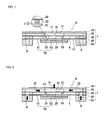
- a piezoelectric microblower A according to this embodiment is an example of a microblower used as an air-cooling blower of an electronic appliance and is formed by stacking on top of one another in order from the top and fixing together a top plate (second wall) 10, a flow-passage-forming plate 20, a separator (first wall) 30, a blower frame 40, the vibrating plate 50 and a bottom plate 60.
- the outer periphery of a diaphragm 51 of the vibrating plate 50 is bonded between the blower frame 40 and the bottom plate 60.
- the top plate 10, the flow-passage-forming plate 20, the separator 30, the blower frame 40 and the bottom plate 60 make up a blower body 1 and are formed of rigid flat-plate-shaped members such as metal plates or rigid resin boards.
- the top plate 10 is formed of a quadrilaterally shaped flat plate and a discharge opening (second opening) 11 is formed so as to penetrate between the two sides thereof in a central portion thereof.
- the flow-passage-forming plate 20 is also a flat plate and has the same outer shape as the top plate 10, and as illustrated in Fig. 3 a central hole (central space) 21, which has a larger diameter than the discharge opening 11, is formed in a central portion thereof.
- a plurality (here, four) of inflow passages 22 are formed so as to extend in radial directions toward the four corners from the central hole 21.
- the separator 30 is also a flat plate having the same outer shape as the top plate 10 and a through hole 31 (first opening), which has substantially the same diameter as the discharge opening 11, is formed in a central portion thereof at a position facing the discharge opening 11.
- the discharge opening 11 and the through hole 31 may have the same diameter or may have different diameters so long as they have a diameter smaller than that of the central hole 21.
- inflow holes 32 are formed at positions corresponding to the outer ends of the inflow passages 22.
- the discharge opening 11, the central hole 21 and the through hole 31 are made to line up on a coaxial line and correspond to a central portion of the vibrating plate 50 to be described later by bonding the top plate 10, the flow-passage-forming plate 20 and the separator 30 to one another.
- the separator 30 be formed of a thin metal plate, since a portion of the separator 30 that corresponds to the central hole 21 will be made to resonate.
- a partition 33 composed of a ring-shaped protrusion, is bonded to a central portion of the separator 30 on the lower surface thereof so as to surround the through hole 31.
- the blower frame 40 is also a flat plate having the same outer shape as the top plate 10 and a cavity 41 having a large diameter is formed in the central portion thereof. Inflow holes 42 are formed in the vicinity of the four corners at positions corresponding to the inflow holes 32.
- a blower chamber 4 is formed by the cavity 41 of the blower frame 40 by bonding the separator 30 and the diaphragm 51 to each other with the blower frame 40 therebetween.
- a region surrounded by the partition 33 forms a resonance space 34 and the diameter of the partition 33 is set such that the resonant frequency of the vibrating plate 50 and the Helmholtz resonant frequency of the resonance space 34 correspond to each other, as will be described later.
- a minute gap ⁇ is provided between the top of the partition 33 and the vibrating plate 50 such that there is no contact therebetween when the vibrating plate 50 is resonantly displaced. The gap ⁇ is smaller than the diameter of the through hole 31.
- the bottom plate 60 is also a flat plate having the same outer shape as the top plate 10 and a cavity 61 having substantially the same shape as the blower chamber 3 is formed in the central portion thereof.
- the bottom plate 60 is formed so as to be thicker than the sum of the thickness of a piezoelectric element 52 and the amount of displacement of the vibrating plate 50 such that even when the microblower A is mounted on a substrate or the like, the piezoelectric element 52 can be prevented from contacting the substrate.
- the cavity 61 forms a cavity that encloses the region surrounding the piezoelectric element 52 of the diaphragm 51 as will be described later.
- Inflow holes 62 are formed in the vicinity of the four corners of the bottom plate 60 at positions corresponding to the inflow holes 32 and 42.
- the vibrating plate 50 has a structure in which the piezoelectric element 52, which has a circular shape, is attached to a central portion of the lower surface of the diaphragm 51 with an intermediate plate 53 therebetween.
- the diaphragm 51 a variety of metal materials can be used such as stainless steel or brass, or a resin board composed of a resin material such as glass epoxy resin may be used.
- the piezoelectric element 52 and the intermediate plate 53 are circular plates having a smaller diameter than the cavity 41 of the blower frame 40.
- a single piezoelectric ceramic plate having electrodes on the top and bottom surfaces thereof is used as the piezoelectric element 52 and a unimorph diaphragm is formed by attaching the piezoelectric element 52 to the bottom surface (surface on opposite side to the blower chamber 3) of the diaphragm 51 with the intermediate plate 53 therebetween.
- the intermediate plate 53 is composed of an elastic plate similarly to the diaphragm 51 and when the vibrating plate 50 bendingly deforms, the neutral plane of displacement is set so as to fall within the range of the thickness of the intermediate plate 53.
- Inflow holes 51a are formed in the vicinity of the four corners of the diaphragm 51 at positions corresponding to the inflow holes 32, 42 and 62.
- Inflow openings 8 in each of which one end thereof is open in the downward direction and the other end thereof communicates with the inflow passages 22 are formed by the inflow holes 32, 42, 62 and 51 a.
- the vibrating plate 50 is resonantly driven in a bending mode by applying an alternating voltage (sine wave or square-shaped wave) having a predetermined frequency to the piezoelectric element 52.
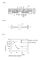
- Fig. 4 illustrates a state in which the vibrating plate 50 is resonantly driven in the third-order mode, the central portion and the peripheral portion of the vibrating plate 50 being displaced in opposite directions to each other.
- the partition 33 is provided in the vicinity of a node point where the displacement is small, whereby the top of the partition 33 can be made to be as close to the vibrating plate 50 as possible. That is, the gap ⁇ can be made as small as possible and the resonant frequency of the resonance space 34 and the effect of the resonance can be stabilized.
- the vibrating plate 50 could be resonantly driven in the first-order resonance mode, but since the node point is positioned at the inner peripheral edge of the cavity 41 of the blower chamber 4 in the first-order resonance mode, the position of the partition could not be made to match that of the node point. Furthermore, in contrast to in the case where resonant driving is performed in the first-order resonance mode and there is a possibility that the first-order resonant frequency will fall within the audible range of humans, for the third-order resonance mode, since the frequency is beyond the audible range, noise can be prevented.
- the vibrating plate 50 is illustrated as having a structure in which the intermediate plate 53 is sandwiched between the diaphragm 51 and the piezoelectric element 52, but a vibrating plate in which the piezoelectric element 52 is directly attached to the diaphragm 51 may be used instead.
- the operation of the piezoelectric microblower A having the above-described structure will be described.
- the vibrating plate 50 is resonantly driven in the first-order resonance mode or the third-order resonance mode and as a result the distance between the first opening 31 of the blower chamber 4 and the vibrating plate 50 changes.
- the distance between the first opening 31 of the blower chamber 4 and the vibrating plate 50 increases, the air inside the central space 21 is sucked into the blower chamber 4 through the first opening 31, and conversely when the distance between the first opening 31 of the blower chamber 4 and the vibrating plate 50 decreases, the air inside the blower chamber 4 is expelled into the central space 21 through the first opening 31.
- the vibrating plate 50 is driven at a high frequency and therefore a high-speed/high-energy air flow expelled from the first opening 31 into the central space 21 is expelled from the second opening 11 through the central space 21. At this time, the air in the central space 21 is expelled from the second opening 11 while being sucked in and therefore a continuous flow of air from the inflow passages 22 into the central space 21 is generated and the air is continuously expelled from the second opening 11 as a jet flow.
- Fig. 5 illustrates a piezoelectric microblower according to a second embodiment of the present invention.
- the structure of a microblower B of this embodiment is the same as that of the piezoelectric microblower A of the first embodiment except for that a ring-shaped piezoelectric element 52a is attached to the upper surface of the diaphragm 51 with a ring-shaped intermediate plate 53a therebetween to form a vibrating plate 50a and therefore the same reference numerals are used and redundant description is omitted.
- the diaphragm 51 deforms as illustrated in Fig. 6 . That is, the displacement of the central portion of the diaphragm 51 becomes markedly large compared with that at the peripheral portion.
- the central portion of the diaphragm 51 where the displacement is greatest can be made to correspond to the resonant space 34 by making the inner diameter of the piezoelectric element 52a be equal to or less than the inner diameter of the partition 33, and the flow rate can be thereby increased.
- the amount of displacement of the central portion of the separator 30 facing the central portion of the diaphragm 51 also becomes large due to the amount of displacement of the central portion of the diaphragm 51 being large and a further increase in the flow rate can be realized.
- the piezoelectric element 52a may be directly attached to the diaphragm 51 by omitting the intermediate plate 53a.
- the microblower B was manufactured under the below conditions, the diameter of the resonance space (partition) was changed and Fig. 7 illustrates an evaluation of the relationship between the diameter of the resonance space and the flow rate characteristics.
- a unimorph plate was prepared in which the intermediate plate, which was composed of an SUS plate with a thickness of 0.15 mm, an outer diameter of 12 mm and an inner diameter of 5 mm, and the piezoelectric element, which was composed of a single PZT plate with a thickness of 0.2 mm, an outer diameter of 12 mm and an inner diameter of 5 mm, were attached onto the diaphragm composed of a 42 Ni plate with a thickness of 0.08 mm.
- the above-described structural components were stacked on top of one another and fixed to one another such that the microblower B having a length of 15 mm, a width of 15 mm and a height of 1.5 mm was manufactured. Furthermore, for comparison, a microblower was manufactured in which a partition was not formed in the blower chamber and in which the blower chamber had an inner diameter of 10 mm. In this experiment, driving was performed by applying a sine-wave voltage of 26.5 kHz and 30 Vpp to the vibrating plate. This frequency is a frequency beyond the audible range of humans.
- the resonant frequency of the resonance space at a volume in the vicinity of the point at which characteristics of the flow rate are best is close to the driving frequency of the vibrating plate and as a result the air in the vicinity of the first opening resonates and the air exits and enters rapidly.
- the gap ⁇ was 0.05 mm but there is no particular limitation on the value thereof. So long as the vibrating plate and the partition do not contact each other, the same result can be obtained for values of 0.01 to 0.1 mm.
- Fig. 8 illustrates a piezoelectric microblower according to a third embodiment of the present invention.
- a microblower C of this embodiment is the same as the piezoelectric microblower A of the first embodiment, except that the partition 33 is fixedly bonded to the top surface of the diaphragm 51.
- the partition 33 also vibrates up and down with the resonant driving of the vibrating plate 50 and therefore it is necessary to provide a predetermined gap ⁇ between the partition 33 and the separator 30 facing the top thereof.
- the position of the partition 33 is set to be in the vicinity of a node point of the vibrating plate 50, vibration of the partition 33 can be suppressed, which is desirable.
- Fig. 9 illustrates a piezoelectric microblower according to a fourth embodiment of the present invention.
- the vibrating plate 50a instead of the vibrating plate 50 of the piezoelectric microblower of the third embodiment, the vibrating plate 50a is used having the ring-shaped piezoelectric element 52a and intermediate plate 53a.
- the inner diameter of the piezoelectric element 52a is made to be equal to or less than the inner diameter of the partition 33 and thereby the central portion of the diaphragm 51 where the displacement is greatest can be made to correspond to the resonance space 34 and the flow rate can be thereby increased.
- Fig. 10 illustrates a piezoelectric microblower according to a fifth embodiment of the present invention and parts the same as those of the piezoelectric microblower A of the first embodiment are denoted by the same symbols.
- the blower frame 40 is made to extend toward the inner diameter side and an opening 44 is formed in the center of the extended portion (partition) 43.
- the resonance space 34 is formed inside the opening 44.
- a thin spacer 45 is disposed between the blower frame 40 and the diaphragm 51, and a minute gap ⁇ is provided between the vibrating plate 50 and the extended portion 43 of the blower frame 40 by this spacer.
- the partition 43 is formed as a step that extends toward the inside from the inner peripheral edge of the blower chamber.
- the blower chamber is substantially equivalent to the resonance space 34.
- Fig. 11 illustrates a piezoelectric microblower according to a sixth embodiment of the present invention.
- the vibrating plate 50a instead of the vibrating plate 50 of the piezoelectric microblower E of the fifth embodiment, the vibrating plate 50a having the ring-shaped piezoelectric element 52a and intermediate plate 53a is used.
- the inner diameter of the piezoelectric element 52a is made to be equal to or less than the inner diameter of the resonance space 34 and thereby the central portion of the diaphragm 51 at which the displacement is greatest can be made to correspond to the resonance space 34 and the flow rate can be thereby increased.
Landscapes
- Engineering & Computer Science (AREA)
- Mechanical Engineering (AREA)
- General Engineering & Computer Science (AREA)
- Reciprocating Pumps (AREA)
- Structures Of Non-Positive Displacement Pumps (AREA)
Applications Claiming Priority (2)
| Application Number | Priority Date | Filing Date | Title |
|---|---|---|---|
| JP2008147548 | 2008-06-05 | ||
| PCT/JP2009/059944 WO2009148005A1 (fr) | 2008-06-05 | 2009-06-01 | Microsoufflante piézoélectrique |
Publications (3)
| Publication Number | Publication Date |
|---|---|
| EP2312158A1 true EP2312158A1 (fr) | 2011-04-20 |
| EP2312158A4 EP2312158A4 (fr) | 2015-03-04 |
| EP2312158B1 EP2312158B1 (fr) | 2016-04-27 |
Family
ID=41398083
Family Applications (1)
| Application Number | Title | Priority Date | Filing Date |
|---|---|---|---|
| EP09758272.0A Active EP2312158B1 (fr) | 2008-06-05 | 2009-06-01 | Microsoufflante piézoélectrique |
Country Status (5)
| Country | Link |
|---|---|
| US (1) | US8684707B2 (fr) |
| EP (1) | EP2312158B1 (fr) |
| JP (1) | JP5110159B2 (fr) |
| CN (1) | CN102057163B (fr) |
| WO (1) | WO2009148005A1 (fr) |
Cited By (4)
| Publication number | Priority date | Publication date | Assignee | Title |
|---|---|---|---|---|
| EP2767715A4 (fr) * | 2011-10-11 | 2015-12-23 | Murata Manufacturing Co | Dispositif de commande de fluide, et procédé de réglage de celui-ci |
| US20160377072A1 (en) * | 2015-06-25 | 2016-12-29 | Koge Micro Tech Co., Ltd. | Piezoelectric pump and operating method thereof |
| EP4006367A1 (fr) | 2020-11-27 | 2022-06-01 | European Space Agency | Système de palier à gaz |
| EP4411139A4 (fr) * | 2021-11-25 | 2024-12-18 | Huawei Technologies Co., Ltd. | Appareil microfluidique et dispositif électronique |
Families Citing this family (63)
| Publication number | Priority date | Publication date | Assignee | Title |
|---|---|---|---|---|
| US8418934B2 (en) | 2008-08-26 | 2013-04-16 | General Electric Company | System and method for miniaturization of synthetic jets |
| JP5533823B2 (ja) * | 2011-09-06 | 2014-06-25 | 株式会社村田製作所 | 流体制御装置 |
| JP5528404B2 (ja) | 2011-09-06 | 2014-06-25 | 株式会社村田製作所 | 流体制御装置 |
| CN104364526B (zh) * | 2012-06-11 | 2016-08-24 | 株式会社村田制作所 | 鼓风机 |
| TWI573012B (zh) * | 2013-08-12 | 2017-03-01 | 奇鋐科技股份有限公司 | 散熱裝置 |
| US9367103B2 (en) | 2013-08-22 | 2016-06-14 | Asia Vital Components Co., Ltd. | Heat dissipation device |
| CN106062364B (zh) * | 2014-02-21 | 2018-03-13 | 株式会社村田制作所 | 鼓风机 |
| WO2015125843A1 (fr) * | 2014-02-21 | 2015-08-27 | 株式会社村田製作所 | Dispositif de commande de fluide et pompe |
| CN104976159B (zh) | 2014-04-11 | 2019-11-01 | 中强光电股份有限公司 | 鼓风机及涡流噪音降低方法 |
| US20150316047A1 (en) * | 2014-04-30 | 2015-11-05 | Texas Instruments Incorporated | Fluid pump having material displaceable responsive to electrical energy |
| EP3168287A4 (fr) | 2014-07-08 | 2018-01-24 | National Institute of Advanced Industrial Science and Technology | Dispositif ainsi que procédé d'amplification d'acide nucléique, et puce pour amplification d'acide nucléique |
| JP6332461B2 (ja) * | 2014-08-20 | 2018-05-30 | 株式会社村田製作所 | ブロア |
| JP6380075B2 (ja) * | 2014-12-15 | 2018-08-29 | 株式会社村田製作所 | ブロア |
| TWI568933B (zh) * | 2015-03-06 | 2017-02-01 | 科際精密股份有限公司 | 壓電泵及壓電泵組合 |
| JP6183574B2 (ja) | 2015-04-27 | 2017-08-23 | 株式会社村田製作所 | ポンプ |
| CN105526135B (zh) * | 2015-12-08 | 2018-02-06 | 北京有色金属研究总院 | 一种反向低驱动电压双侧泵膜无阀静电微泵及其制备方法 |
| US10487820B2 (en) | 2016-01-29 | 2019-11-26 | Microjet Technology Co., Ltd. | Miniature pneumatic device |
| EP3203076B1 (fr) | 2016-01-29 | 2021-05-12 | Microjet Technology Co., Ltd | Dispositif miniature de régulation de fluides |
| EP3203079B1 (fr) | 2016-01-29 | 2021-05-19 | Microjet Technology Co., Ltd | Actionneur piézoélectrique |
| US10584695B2 (en) | 2016-01-29 | 2020-03-10 | Microjet Technology Co., Ltd. | Miniature fluid control device |
| TWI696757B (zh) * | 2016-01-29 | 2020-06-21 | 研能科技股份有限公司 | 微型流體控制裝置 |
| US10385838B2 (en) | 2016-01-29 | 2019-08-20 | Microjet Technology Co., Ltd. | Miniature fluid control device |
| US10529911B2 (en) | 2016-01-29 | 2020-01-07 | Microjet Technology Co., Ltd. | Piezoelectric actuator |
| US10371136B2 (en) | 2016-01-29 | 2019-08-06 | Microjet Technology Co., Ltd. | Miniature pneumatic device |
| US9976673B2 (en) | 2016-01-29 | 2018-05-22 | Microjet Technology Co., Ltd. | Miniature fluid control device |
| US10615329B2 (en) | 2016-01-29 | 2020-04-07 | Microjet Technology Co., Ltd. | Piezoelectric actuator |
| US10378529B2 (en) | 2016-01-29 | 2019-08-13 | Microjet Technology Co., Ltd. | Miniature pneumatic device |
| US10451051B2 (en) | 2016-01-29 | 2019-10-22 | Microjet Technology Co., Ltd. | Miniature pneumatic device |
| US10388849B2 (en) | 2016-01-29 | 2019-08-20 | Microjet Technology Co., Ltd. | Piezoelectric actuator |
| TWI606936B (zh) * | 2016-09-05 | 2017-12-01 | 研能科技股份有限公司 | 流體控制裝置 |
| TWI602995B (zh) | 2016-09-05 | 2017-10-21 | 研能科技股份有限公司 | 流體控制裝置 |
| TWI613367B (zh) * | 2016-09-05 | 2018-02-01 | 研能科技股份有限公司 | 流體控制裝置 |
| TWI625468B (zh) | 2016-09-05 | 2018-06-01 | 研能科技股份有限公司 | 流體控制裝置 |
| TWI683959B (zh) * | 2016-09-05 | 2020-02-01 | 研能科技股份有限公司 | 壓電致動器及其所適用之微型流體控制裝置 |
| US10683861B2 (en) | 2016-11-10 | 2020-06-16 | Microjet Technology Co., Ltd. | Miniature pneumatic device |
| US10655620B2 (en) | 2016-11-10 | 2020-05-19 | Microjet Technology Co., Ltd. | Miniature fluid control device |
| US10746169B2 (en) | 2016-11-10 | 2020-08-18 | Microjet Technology Co., Ltd. | Miniature pneumatic device |
| CN109424522B (zh) * | 2017-08-31 | 2021-02-09 | 研能科技股份有限公司 | 气体输送装置 |
| WO2019111982A1 (fr) * | 2017-12-08 | 2019-06-13 | 株式会社村田製作所 | Pompe |
| US11043444B2 (en) | 2018-08-10 | 2021-06-22 | Frore Systems Inc. | Two-dimensional addessable array of piezoelectric MEMS-based active cooling devices |
| US12089374B2 (en) | 2018-08-10 | 2024-09-10 | Frore Systems Inc. | MEMS-based active cooling systems |
| US11464140B2 (en) | 2019-12-06 | 2022-10-04 | Frore Systems Inc. | Centrally anchored MEMS-based active cooling systems |
| CN112752906B (zh) * | 2018-11-27 | 2023-04-18 | 株式会社村田制作所 | 泵 |
| CN112789407B (zh) * | 2018-11-27 | 2023-02-03 | 株式会社村田制作所 | 泵 |
| CN110043452B (zh) * | 2019-04-26 | 2024-12-24 | 常州威图流体科技有限公司 | 一种新型压电微泵 |
| US11898545B2 (en) | 2019-06-21 | 2024-02-13 | Brane Audio, LLC | Venturi pump systems and methods to use same |
| CN114222859A (zh) * | 2019-09-11 | 2022-03-22 | 京瓷株式会社 | 压电泵以及泵单元 |
| WO2021086873A1 (fr) | 2019-10-30 | 2021-05-06 | Frore System Inc. | Système d'écoulement d'air à base de mems |
| US11796262B2 (en) | 2019-12-06 | 2023-10-24 | Frore Systems Inc. | Top chamber cavities for center-pinned actuators |
| US12193192B2 (en) | 2019-12-06 | 2025-01-07 | Frore Systems Inc. | Cavities for center-pinned actuator cooling systems |
| CN112922817A (zh) * | 2019-12-06 | 2021-06-08 | 研能科技股份有限公司 | 微型鼓风机 |
| US11510341B2 (en) | 2019-12-06 | 2022-11-22 | Frore Systems Inc. | Engineered actuators usable in MEMs active cooling devices |
| US12181077B2 (en) * | 2019-12-16 | 2024-12-31 | Frore Systems Inc. | Virtual valve in a MEMS-based cooling system |
| US12033917B2 (en) | 2019-12-17 | 2024-07-09 | Frore Systems Inc. | Airflow control in active cooling systems |
| CN113661568A (zh) | 2019-12-17 | 2021-11-16 | 福珞尔系统公司 | 用于封闭和开放设备的基于mems的冷却系统 |
| US12052924B2 (en) | 2019-12-20 | 2024-07-30 | Frore Systems Inc. | Method and system for fabricating a piezoelectric device |
| CN111140478B (zh) * | 2020-01-22 | 2024-12-20 | 常州威图流体科技有限公司 | 一种压电微泵及气体控制装置 |
| JP2023126990A (ja) * | 2020-07-31 | 2023-09-13 | Tdk株式会社 | ポンプ及び流体制御装置 |
| WO2022072286A1 (fr) | 2020-10-02 | 2022-04-07 | Frore Systems Inc. | Dissipateur thermique actif |
| WO2022187160A1 (fr) * | 2021-03-02 | 2022-09-09 | Frore Systems Inc. | Mélange d'échappement pour systèmes de refroidissement piézoélectriques |
| US12167564B2 (en) | 2021-03-02 | 2024-12-10 | Frore Systems Inc. | Integration of airjets into computing devices |
| US12453038B2 (en) * | 2024-01-08 | 2025-10-21 | xMEMS Labs, Inc. | Electronic device and airflow generating package |
| WO2026038496A1 (fr) * | 2024-08-13 | 2026-02-19 | ソニーグループ株式会社 | Dispositif de régulation de fluide et son procédé de fabrication |
Family Cites Families (20)
| Publication number | Priority date | Publication date | Assignee | Title |
|---|---|---|---|---|
| US3963380A (en) * | 1975-01-06 | 1976-06-15 | Thomas Jr Lyell J | Micro pump powered by piezoelectric disk benders |
| US4498851A (en) * | 1980-05-02 | 1985-02-12 | Piezo Electric Products, Inc. | Solid state blower |
| JPS58140491A (ja) * | 1982-02-16 | 1983-08-20 | Matsushita Electric Ind Co Ltd | 流れ発生装置 |
| US4595338A (en) * | 1983-11-17 | 1986-06-17 | Piezo Electric Products, Inc. | Non-vibrational oscillating blade piezoelectric blower |
| US4780062A (en) * | 1985-10-09 | 1988-10-25 | Murata Manufacturing Co., Ltd. | Piezoelectric fan |
| US5008582A (en) * | 1988-01-29 | 1991-04-16 | Kabushiki Kaisha Toshiba | Electronic device having a cooling element |
| US4923000A (en) * | 1989-03-03 | 1990-05-08 | Microelectronics And Computer Technology Corporation | Heat exchanger having piezoelectric fan means |
| JPH0727056A (ja) * | 1993-07-06 | 1995-01-27 | Hitachi Ltd | ポンプ |
| JPH09321360A (ja) * | 1996-05-27 | 1997-12-12 | Honda Motor Co Ltd | 圧電ファン |
| US7061161B2 (en) * | 2002-02-15 | 2006-06-13 | Siemens Technology-To-Business Center Llc | Small piezoelectric air pumps with unobstructed airflow |
| CN1179127C (zh) * | 2002-09-03 | 2004-12-08 | 吉林大学 | 多腔压电薄膜驱动泵 |
| GB0308197D0 (en) | 2003-04-09 | 2003-05-14 | The Technology Partnership Plc | Gas flow generator |
| JP2004332705A (ja) | 2003-05-09 | 2004-11-25 | Honda Motor Co Ltd | マイクロポンプ |
| AU2004258530A1 (en) | 2003-07-07 | 2005-01-27 | Georgia Tech Research Corporation | System and method for thermal management using distributed synthetic jet actuators |
| KR100519970B1 (ko) * | 2003-10-07 | 2005-10-13 | 삼성전자주식회사 | 밸브리스 마이크로 공기공급장치 |
| JP4539450B2 (ja) | 2004-11-04 | 2010-09-08 | オムロン株式会社 | 容量型振動センサ及びその製造方法 |
| GB0508194D0 (en) * | 2005-04-22 | 2005-06-01 | The Technology Partnership Plc | Pump |
| US20070090726A1 (en) * | 2005-10-24 | 2007-04-26 | Morris Grant A | Piezoelectric fan |
| JP2008014148A (ja) | 2006-07-03 | 2008-01-24 | Sony Corp | 噴流発生装置及び電子機器 |
| EP2090781B1 (fr) | 2006-12-09 | 2018-08-22 | Murata Manufacturing Co. Ltd. | Micro-ventilateur piézoélectrique |
-
2009
- 2009-06-01 EP EP09758272.0A patent/EP2312158B1/fr active Active
- 2009-06-01 CN CN2009801213498A patent/CN102057163B/zh active Active
- 2009-06-01 WO PCT/JP2009/059944 patent/WO2009148005A1/fr not_active Ceased
- 2009-06-01 JP JP2010515853A patent/JP5110159B2/ja active Active
-
2010
- 2010-12-03 US US12/959,462 patent/US8684707B2/en active Active
Non-Patent Citations (1)
| Title |
|---|
| See references of WO2009148005A1 * |
Cited By (8)
| Publication number | Priority date | Publication date | Assignee | Title |
|---|---|---|---|---|
| EP2767715A4 (fr) * | 2011-10-11 | 2015-12-23 | Murata Manufacturing Co | Dispositif de commande de fluide, et procédé de réglage de celui-ci |
| EP2767715B1 (fr) | 2011-10-11 | 2018-04-04 | Murata Manufacturing Co., Ltd. | Dispositif de commande de fluide, et procédé de réglage de celui-ci |
| EP3346131A1 (fr) * | 2011-10-11 | 2018-07-11 | Murata Manufacturing Co., Ltd. | Appareil de commande de fluides et procédé de réglage d'appareil de commande de fluides |
| US20160377072A1 (en) * | 2015-06-25 | 2016-12-29 | Koge Micro Tech Co., Ltd. | Piezoelectric pump and operating method thereof |
| US10393109B2 (en) * | 2015-06-25 | 2019-08-27 | Koge Micro Tech Co., Ltd. | Piezoelectric pump having a vibrating piece having a vibrating piece having a central zone, a peripheral zone, a first recess, a stopper, at least one position limiting wall, and at least one through groove and operating method thereof |
| EP4006367A1 (fr) | 2020-11-27 | 2022-06-01 | European Space Agency | Système de palier à gaz |
| US12077322B2 (en) | 2020-11-27 | 2024-09-03 | European Space Agency | Gas bearing system |
| EP4411139A4 (fr) * | 2021-11-25 | 2024-12-18 | Huawei Technologies Co., Ltd. | Appareil microfluidique et dispositif électronique |
Also Published As
| Publication number | Publication date |
|---|---|
| CN102057163B (zh) | 2013-10-30 |
| JPWO2009148005A1 (ja) | 2011-10-27 |
| US20110070109A1 (en) | 2011-03-24 |
| EP2312158A4 (fr) | 2015-03-04 |
| EP2312158B1 (fr) | 2016-04-27 |
| CN102057163A (zh) | 2011-05-11 |
| WO2009148005A1 (fr) | 2009-12-10 |
| JP5110159B2 (ja) | 2012-12-26 |
| US8684707B2 (en) | 2014-04-01 |
Similar Documents
| Publication | Publication Date | Title |
|---|---|---|
| EP2312158B1 (fr) | Microsoufflante piézoélectrique | |
| US11047376B2 (en) | Actuator support structure and pump device | |
| JP6052475B2 (ja) | 流体制御装置 | |
| JP6617821B2 (ja) | 流体制御装置 | |
| CN107923385B (zh) | 鼓风机 | |
| EP2812573B1 (fr) | Pompe a disques avec actionneur avancé | |
| CN111492142B (zh) | 泵 | |
| CN102597519B (zh) | 压电微型鼓风机 | |
| US10125760B2 (en) | Pump | |
| JP6575634B2 (ja) | ブロア | |
| JP2011027079A (ja) | マイクロブロア | |
| TWI625469B (zh) | 低共振音頻之合成噴流結構 |
Legal Events
| Date | Code | Title | Description |
|---|---|---|---|
| PUAI | Public reference made under article 153(3) epc to a published international application that has entered the european phase |
Free format text: ORIGINAL CODE: 0009012 |
|
| 17P | Request for examination filed |
Effective date: 20101231 |
|
| AK | Designated contracting states |
Kind code of ref document: A1 Designated state(s): AT BE BG CH CY CZ DE DK EE ES FI FR GB GR HR HU IE IS IT LI LT LU LV MC MK MT NL NO PL PT RO SE SI SK TR |
|
| AX | Request for extension of the european patent |
Extension state: AL BA RS |
|
| DAX | Request for extension of the european patent (deleted) | ||
| A4 | Supplementary search report drawn up and despatched |
Effective date: 20150129 |
|
| RIC1 | Information provided on ipc code assigned before grant |
Ipc: F04B 45/047 20060101AFI20150123BHEP |
|
| GRAP | Despatch of communication of intention to grant a patent |
Free format text: ORIGINAL CODE: EPIDOSNIGR1 |
|
| INTG | Intention to grant announced |
Effective date: 20151111 |
|
| GRAS | Grant fee paid |
Free format text: ORIGINAL CODE: EPIDOSNIGR3 |
|
| GRAA | (expected) grant |
Free format text: ORIGINAL CODE: 0009210 |
|
| AK | Designated contracting states |
Kind code of ref document: B1 Designated state(s): AT BE BG CH CY CZ DE DK EE ES FI FR GB GR HR HU IE IS IT LI LT LU LV MC MK MT NL NO PL PT RO SE SI SK TR |
|
| REG | Reference to a national code |
Ref country code: GB Ref legal event code: FG4D |
|
| REG | Reference to a national code |
Ref country code: CH Ref legal event code: EP |
|
| REG | Reference to a national code |
Ref country code: AT Ref legal event code: REF Ref document number: 795124 Country of ref document: AT Kind code of ref document: T Effective date: 20160515 |
|
| REG | Reference to a national code |
Ref country code: IE Ref legal event code: FG4D |
|
| REG | Reference to a national code |
Ref country code: DE Ref legal event code: R096 Ref document number: 602009038226 Country of ref document: DE |
|
| REG | Reference to a national code |
Ref country code: LT Ref legal event code: MG4D |
|
| REG | Reference to a national code |
Ref country code: NL Ref legal event code: MP Effective date: 20160427 |
|
| REG | Reference to a national code |
Ref country code: AT Ref legal event code: MK05 Ref document number: 795124 Country of ref document: AT Kind code of ref document: T Effective date: 20160427 |
|
| PG25 | Lapsed in a contracting state [announced via postgrant information from national office to epo] |
Ref country code: NL Free format text: LAPSE BECAUSE OF FAILURE TO SUBMIT A TRANSLATION OF THE DESCRIPTION OR TO PAY THE FEE WITHIN THE PRESCRIBED TIME-LIMIT Effective date: 20160427 |
|
| PG25 | Lapsed in a contracting state [announced via postgrant information from national office to epo] |
Ref country code: LT Free format text: LAPSE BECAUSE OF FAILURE TO SUBMIT A TRANSLATION OF THE DESCRIPTION OR TO PAY THE FEE WITHIN THE PRESCRIBED TIME-LIMIT Effective date: 20160427 Ref country code: PL Free format text: LAPSE BECAUSE OF FAILURE TO SUBMIT A TRANSLATION OF THE DESCRIPTION OR TO PAY THE FEE WITHIN THE PRESCRIBED TIME-LIMIT Effective date: 20160427 Ref country code: NO Free format text: LAPSE BECAUSE OF FAILURE TO SUBMIT A TRANSLATION OF THE DESCRIPTION OR TO PAY THE FEE WITHIN THE PRESCRIBED TIME-LIMIT Effective date: 20160727 Ref country code: FI Free format text: LAPSE BECAUSE OF FAILURE TO SUBMIT A TRANSLATION OF THE DESCRIPTION OR TO PAY THE FEE WITHIN THE PRESCRIBED TIME-LIMIT Effective date: 20160427 |
|
| PG25 | Lapsed in a contracting state [announced via postgrant information from national office to epo] |
Ref country code: PT Free format text: LAPSE BECAUSE OF FAILURE TO SUBMIT A TRANSLATION OF THE DESCRIPTION OR TO PAY THE FEE WITHIN THE PRESCRIBED TIME-LIMIT Effective date: 20160829 Ref country code: GR Free format text: LAPSE BECAUSE OF FAILURE TO SUBMIT A TRANSLATION OF THE DESCRIPTION OR TO PAY THE FEE WITHIN THE PRESCRIBED TIME-LIMIT Effective date: 20160728 Ref country code: SE Free format text: LAPSE BECAUSE OF FAILURE TO SUBMIT A TRANSLATION OF THE DESCRIPTION OR TO PAY THE FEE WITHIN THE PRESCRIBED TIME-LIMIT Effective date: 20160427 Ref country code: LV Free format text: LAPSE BECAUSE OF FAILURE TO SUBMIT A TRANSLATION OF THE DESCRIPTION OR TO PAY THE FEE WITHIN THE PRESCRIBED TIME-LIMIT Effective date: 20160427 Ref country code: HR Free format text: LAPSE BECAUSE OF FAILURE TO SUBMIT A TRANSLATION OF THE DESCRIPTION OR TO PAY THE FEE WITHIN THE PRESCRIBED TIME-LIMIT Effective date: 20160427 Ref country code: ES Free format text: LAPSE BECAUSE OF FAILURE TO SUBMIT A TRANSLATION OF THE DESCRIPTION OR TO PAY THE FEE WITHIN THE PRESCRIBED TIME-LIMIT Effective date: 20160427 Ref country code: AT Free format text: LAPSE BECAUSE OF FAILURE TO SUBMIT A TRANSLATION OF THE DESCRIPTION OR TO PAY THE FEE WITHIN THE PRESCRIBED TIME-LIMIT Effective date: 20160427 |
|
| PG25 | Lapsed in a contracting state [announced via postgrant information from national office to epo] |
Ref country code: BE Free format text: LAPSE BECAUSE OF FAILURE TO SUBMIT A TRANSLATION OF THE DESCRIPTION OR TO PAY THE FEE WITHIN THE PRESCRIBED TIME-LIMIT Effective date: 20160427 Ref country code: IT Free format text: LAPSE BECAUSE OF FAILURE TO SUBMIT A TRANSLATION OF THE DESCRIPTION OR TO PAY THE FEE WITHIN THE PRESCRIBED TIME-LIMIT Effective date: 20160427 |
|
| REG | Reference to a national code |
Ref country code: DE Ref legal event code: R097 Ref document number: 602009038226 Country of ref document: DE |
|
| PG25 | Lapsed in a contracting state [announced via postgrant information from national office to epo] |
Ref country code: CZ Free format text: LAPSE BECAUSE OF FAILURE TO SUBMIT A TRANSLATION OF THE DESCRIPTION OR TO PAY THE FEE WITHIN THE PRESCRIBED TIME-LIMIT Effective date: 20160427 Ref country code: DK Free format text: LAPSE BECAUSE OF FAILURE TO SUBMIT A TRANSLATION OF THE DESCRIPTION OR TO PAY THE FEE WITHIN THE PRESCRIBED TIME-LIMIT Effective date: 20160427 Ref country code: RO Free format text: LAPSE BECAUSE OF FAILURE TO SUBMIT A TRANSLATION OF THE DESCRIPTION OR TO PAY THE FEE WITHIN THE PRESCRIBED TIME-LIMIT Effective date: 20160427 Ref country code: MC Free format text: LAPSE BECAUSE OF FAILURE TO SUBMIT A TRANSLATION OF THE DESCRIPTION OR TO PAY THE FEE WITHIN THE PRESCRIBED TIME-LIMIT Effective date: 20160427 Ref country code: SK Free format text: LAPSE BECAUSE OF FAILURE TO SUBMIT A TRANSLATION OF THE DESCRIPTION OR TO PAY THE FEE WITHIN THE PRESCRIBED TIME-LIMIT Effective date: 20160427 Ref country code: EE Free format text: LAPSE BECAUSE OF FAILURE TO SUBMIT A TRANSLATION OF THE DESCRIPTION OR TO PAY THE FEE WITHIN THE PRESCRIBED TIME-LIMIT Effective date: 20160427 |
|
| REG | Reference to a national code |
Ref country code: CH Ref legal event code: PL |
|
| PLBE | No opposition filed within time limit |
Free format text: ORIGINAL CODE: 0009261 |
|
| STAA | Information on the status of an ep patent application or granted ep patent |
Free format text: STATUS: NO OPPOSITION FILED WITHIN TIME LIMIT |
|
| GBPC | Gb: european patent ceased through non-payment of renewal fee |
Effective date: 20160727 |
|
| REG | Reference to a national code |
Ref country code: IE Ref legal event code: MM4A |
|
| REG | Reference to a national code |
Ref country code: FR Ref legal event code: ST Effective date: 20170228 |
|
| 26N | No opposition filed |
Effective date: 20170130 |
|
| PG25 | Lapsed in a contracting state [announced via postgrant information from national office to epo] |
Ref country code: CH Free format text: LAPSE BECAUSE OF NON-PAYMENT OF DUE FEES Effective date: 20160630 Ref country code: FR Free format text: LAPSE BECAUSE OF NON-PAYMENT OF DUE FEES Effective date: 20160630 Ref country code: LI Free format text: LAPSE BECAUSE OF NON-PAYMENT OF DUE FEES Effective date: 20160630 |
|
| PG25 | Lapsed in a contracting state [announced via postgrant information from national office to epo] |
Ref country code: IE Free format text: LAPSE BECAUSE OF NON-PAYMENT OF DUE FEES Effective date: 20160601 Ref country code: SI Free format text: LAPSE BECAUSE OF FAILURE TO SUBMIT A TRANSLATION OF THE DESCRIPTION OR TO PAY THE FEE WITHIN THE PRESCRIBED TIME-LIMIT Effective date: 20160427 Ref country code: GB Free format text: LAPSE BECAUSE OF NON-PAYMENT OF DUE FEES Effective date: 20160727 |
|
| PG25 | Lapsed in a contracting state [announced via postgrant information from national office to epo] |
Ref country code: CY Free format text: LAPSE BECAUSE OF FAILURE TO SUBMIT A TRANSLATION OF THE DESCRIPTION OR TO PAY THE FEE WITHIN THE PRESCRIBED TIME-LIMIT Effective date: 20160427 Ref country code: HU Free format text: LAPSE BECAUSE OF FAILURE TO SUBMIT A TRANSLATION OF THE DESCRIPTION OR TO PAY THE FEE WITHIN THE PRESCRIBED TIME-LIMIT; INVALID AB INITIO Effective date: 20090601 |
|
| PG25 | Lapsed in a contracting state [announced via postgrant information from national office to epo] |
Ref country code: MK Free format text: LAPSE BECAUSE OF FAILURE TO SUBMIT A TRANSLATION OF THE DESCRIPTION OR TO PAY THE FEE WITHIN THE PRESCRIBED TIME-LIMIT Effective date: 20160427 Ref country code: TR Free format text: LAPSE BECAUSE OF FAILURE TO SUBMIT A TRANSLATION OF THE DESCRIPTION OR TO PAY THE FEE WITHIN THE PRESCRIBED TIME-LIMIT Effective date: 20160427 Ref country code: LU Free format text: LAPSE BECAUSE OF NON-PAYMENT OF DUE FEES Effective date: 20160601 Ref country code: IS Free format text: LAPSE BECAUSE OF FAILURE TO SUBMIT A TRANSLATION OF THE DESCRIPTION OR TO PAY THE FEE WITHIN THE PRESCRIBED TIME-LIMIT Effective date: 20160427 Ref country code: MT Free format text: LAPSE BECAUSE OF NON-PAYMENT OF DUE FEES Effective date: 20160630 |
|
| PG25 | Lapsed in a contracting state [announced via postgrant information from national office to epo] |
Ref country code: BG Free format text: LAPSE BECAUSE OF FAILURE TO SUBMIT A TRANSLATION OF THE DESCRIPTION OR TO PAY THE FEE WITHIN THE PRESCRIBED TIME-LIMIT Effective date: 20160427 |
|
| PGFP | Annual fee paid to national office [announced via postgrant information from national office to epo] |
Ref country code: DE Payment date: 20250618 Year of fee payment: 17 |