EP2312270A1 - Vorrichtung zur Überprüfung der Genauigkeit einer von einer Arbeitsspindel und/oder einem Maschinentisch auszuführenden Kreisbahn einer Werkzeugmaschine - Google Patents
Vorrichtung zur Überprüfung der Genauigkeit einer von einer Arbeitsspindel und/oder einem Maschinentisch auszuführenden Kreisbahn einer Werkzeugmaschine Download PDFInfo
- Publication number
- EP2312270A1 EP2312270A1 EP10186955A EP10186955A EP2312270A1 EP 2312270 A1 EP2312270 A1 EP 2312270A1 EP 10186955 A EP10186955 A EP 10186955A EP 10186955 A EP10186955 A EP 10186955A EP 2312270 A1 EP2312270 A1 EP 2312270A1
- Authority
- EP
- European Patent Office
- Prior art keywords
- pivot bearing
- stator
- work spindle
- data
- pivot
- Prior art date
- Legal status (The legal status is an assumption and is not a legal conclusion. Google has not performed a legal analysis and makes no representation as to the accuracy of the status listed.)
- Granted
Links
Images


Classifications
-
- G—PHYSICS
- G01—MEASURING; TESTING
- G01B—MEASURING LENGTH, THICKNESS OR SIMILAR LINEAR DIMENSIONS; MEASURING ANGLES; MEASURING AREAS; MEASURING IRREGULARITIES OF SURFACES OR CONTOURS
- G01B21/00—Measuring arrangements or details thereof, where the measuring technique is not covered by the other groups of this subclass, unspecified or not relevant
- G01B21/02—Measuring arrangements or details thereof, where the measuring technique is not covered by the other groups of this subclass, unspecified or not relevant for measuring length, width, or thickness
- G01B21/04—Measuring arrangements or details thereof, where the measuring technique is not covered by the other groups of this subclass, unspecified or not relevant for measuring length, width, or thickness by measuring coordinates of points
- G01B21/042—Calibration or calibration artifacts
-
- G—PHYSICS
- G05—CONTROLLING; REGULATING
- G05B—CONTROL OR REGULATING SYSTEMS IN GENERAL; FUNCTIONAL ELEMENTS OF SUCH SYSTEMS; MONITORING OR TESTING ARRANGEMENTS FOR SUCH SYSTEMS OR ELEMENTS
- G05B19/00—Program-control systems
- G05B19/02—Program-control systems electric
- G05B19/18—Numerical control [NC], i.e. automatically operating machines, in particular machine tools, e.g. in a manufacturing environment, so as to execute positioning, movement or co-ordinated operations by means of program data in numerical form
- G05B19/401—Numerical control [NC], i.e. automatically operating machines, in particular machine tools, e.g. in a manufacturing environment, so as to execute positioning, movement or co-ordinated operations by means of program data in numerical form characterised by control arrangements for measuring, e.g. calibration and initialisation, measuring workpiece for machining purposes
-
- G—PHYSICS
- G05—CONTROLLING; REGULATING
- G05B—CONTROL OR REGULATING SYSTEMS IN GENERAL; FUNCTIONAL ELEMENTS OF SUCH SYSTEMS; MONITORING OR TESTING ARRANGEMENTS FOR SUCH SYSTEMS OR ELEMENTS
- G05B2219/00—Program-control systems
- G05B2219/30—Nc systems
- G05B2219/37—Measurements
- G05B2219/37022—Detector, measuring device incorporated within workpiece holder
-
- G—PHYSICS
- G05—CONTROLLING; REGULATING
- G05B—CONTROL OR REGULATING SYSTEMS IN GENERAL; FUNCTIONAL ELEMENTS OF SUCH SYSTEMS; MONITORING OR TESTING ARRANGEMENTS FOR SUCH SYSTEMS OR ELEMENTS
- G05B2219/00—Program-control systems
- G05B2219/30—Nc systems
- G05B2219/37—Measurements
- G05B2219/37619—Characteristics of machine, deviation of movement, gauge
Definitions
- the invention relates to a device for checking the accuracy of a work spindle and / or a machine table to be executed circular path, in particular an NC-controlled machine tool, with a coaxially attachable to the work spindle clamping element, a fastened to the clamping element first pivot bearing with a coaxial to the work spindle axis of rotation and an orthogonal thereto pivot axis for a first pivot bearing, a pivot bearing having measuring arm, a measuring arm receiving adjustment with a second pivot bearing with a pivot axis of the first pivot bearing pivot axis, a second pivot bearing with a parallel to the work spindle rotation axis and with a second rotary bearing bearing stator, wherein a length measuring system for determining a radial deviation of the work spindle is provided by a circular path in the measuring arm.
- a device of this kind is already out of the EP 1 826 642 A1 known. With this device, the movement of a work spindle along a circular path, for example, for the production of circular cylindrical surfaces of workpieces, can be measured with high accuracy.
- a similar device is from the DE 295 12 250 U1 and the EP 0 526 056 A1 known. These devices offer the advantage of no longer having to use correspondingly different reference cylinders for checking the accuracy of different diameters of circular cylindrical surfaces. However, these devices are limited in their resolution and accuracy due to the inductive data acquisition. In addition, a drift deviation of up to ⁇ 9 ⁇ m to 2 mm gauge length must be accepted. This deviation is often too great for high-precision machine tools.
- the invention has for its object to provide a device of the type described, with the more accurate measurements can be performed.
- the length measuring system has a glass rod carrying a marking and a reading device.
- the length measuring system having a glass rod and a reading device has the significant advantage that it has a negligibly small drift deviation of ⁇ 1 ⁇ m with a measuring length of 5 mm.
- the temperature-related change in length of the glass rod is negligibly small and the reading device is arranged so that changes in their dimensions have little or no effect.
- the reading device lies in the vertical axis of rotation of the second rotary bearing, so that a change in length is neutral.
- the circular path can be measured in each of the three levels (X, Y and Z plane).
- the glass rod is attached to a ram connected to the first pivot bearing. It can also be defined via a carrier on the adjusting device.
- the reading device is attached to the adjusting device via a carrier. Alternatively, it may also be attached to a plunger connected to the first pivot bearing. So it can be moved to the glass rod or the reading device.
- the glass rod is provided with a code facing the reading device, in particular with a bar code.
- This bar code forming the mark can be printed in very high resolution e.g. by etching or imprinting, are mounted on the glass rod and read by the reading device.
- the reading device of an optical nature, then the data acquisition takes place without contact and is thus wear-free and immune to interference.
- the measuring arm has an electronic device for digitizing the measured data. These are transmitted by wire.
- the device has a time measuring device for temporally coupling the measured data. In this way, not only the radial deviation but also the time differences between the trigger signals can be detected.
- the rotating unit has a transmitting and / or receiving device for the wireless transmission of data to the stator and / or to an external transmitting and / or receiving device. This process can be done during the measurement or after completion of the measurement.
- the stator has a transmitting and / or receiving device for the wireless transmission of data to an external transmitting and / or receiving device.
- the processing of the data can be done in this way in an external system and the memory in the stator can be deleted.
- the transmitting and / or receiving device operates by radio or Bluetooth standard.
- the stator has a device, in particular an encoder for detecting the rotational speed of the second pivot bearing.
- a storage device for storing the speed data detected by means of the device is provided in the stator.
- an evaluation device for correlating the speed data and the data of the length measuring system is provided in the stator.
- the synchronous speed of the work spindle can now also be measured. The advantage is that it can be determined from this measurement, whether the determined circular error is to be attributed to the electrical drives, electronics and / or to the mechanics of the machine tool.
- FIG. 1 is the reference numeral 10, a verification device shown, with which of a work spindle 12, for example, from a machine tool whose concentricity or its radial deviation can be measured from a circular path.
- the inspection device 10 has a clamping element 14, which is fastened with its clamping member 16 coaxially to the work spindle 12, so that the clamping element 14 passes through the circular path to be measured.
- the clamping element 14 has a pivot bearing 18 whose axis of rotation 20 is coaxial with the axis of rotation 22 of the work spindle 12. Below the pivot bearing 18 is a pivot bearing 24 having a pivot axis 26 orthogonal to the axis of rotation 20, on which a measuring arm 28 is pivotally fixed.
- the measuring arm 28 is mounted in an adjusting device 34, wherein it can be moved and fixed in the adjusting device 34 in the direction of the double arrow 36.
- a pivot bearing 38 is provided with a pivot axis 40 which is parallel to the pivot axis 26.
- a second pivot bearing 42 whose axis of rotation 44 is orthogonal to the pivot axis 40 and parallel to the axis of rotation 20 of the pivot bearing 18 and axis of rotation 22 of the work spindle 12 runs.
- the pivot bearing 42 is of a Stator 46 is held, which is fastened to a clamping plate 48 which rests on a machine table 50 of the machine tool to be measured.
- the radial deviation is measured and digitized by the circular path of the working spindle 12 revolving around the stator 46 or its axis of rotation 44, as will be described in detail below.
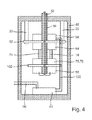
- stator 46 In the stator 46 is, as in FIG. 4 illustrated, attached via two spacers 30, a board 52 which is an encoder 54 opposite.
- This encoder 54 is seated on a hollow shaft 56 forming the axis of rotation 44, in which the cable 32 is guided to an evaluation electronics 58.
- the synchronous speed about the axis of rotation 44 is measured with the encoder 54.
- This encoder 52 is connected to lines 74 with a latch 76 having a transmitting and / or receiving device 78 for transmitting the data to a stationary transmitting and / or receiving device 80, which is provided at the bottom of the stator 46 and with which the Data to an external unit 60, for example, a notebook, a PC or other data processing system are transmitted. This can also be done with a line 96.
- a slip ring 98 On the stationary board 52 also the stationary part of a slip ring 98 is fixed, whereas the other part is supported by the hollow shaft 56.
- the slip ring 98 serves to transmit the energy required for the measurement processes, which is obtained via a line 100.
- the Latch 76 and the transmitting and / or receiving device 78 are supported by a board 102 fixed to the hollow shaft.
- FIG. 2 shows a longitudinal section through the measuring arm 28, which carries a length measuring system 64 in a housing 62.
- This has a plunger 66, whose free end is coupled to a punch 68, for example by means of a screw, wherein the punch 68 is connected to the pivot bearing 24.
- the punch 68 is smooth over a longitudinal bearing 70 in the direction of the double arrow 92 (FIG. FIG. 3 ) and has a Vercardkupplung 72.
- an electronic device 104 for digitizing the measurement data, which is connected to the cable 32.
- the length measuring system 64 which in detail in the FIG. 3 a reading device 84, which is arranged in a carrier 86. With this reading device 84 is a mark 88, which in the FIG. 3 only hinted at as a bar code, read on a glass rod 90, which in turn is attached to the plunger 66. This plunger 66 moves in the direction of the double arrow 92, which corresponds to the deviation 82 when the measuring arm 28 is horizontal.
- the data determined with the reading device 84 are processed in the electronic device 76 and transmitted via the transmitting and / or receiving device 80.
- the length measuring device 64 according to the invention has the significant advantage that it operates without contact and has no temperature-induced drift.
- up to five temperature sensors can be connected to the device 10 according to the invention.
- the individual temperature sensors are connected with a connection cable with a length between 5 and 10 m to a separate interface with five inputs and a data output.
- this interface is a detection board with a Memory device.
- the interface is connected via a data line with the device 10 according to the invention and thus with the integrated microcomputer.
- measured values of the circular measurement are recorded, processed and stored in the microcomputer in the device 10.
- the microcomputer in the device 10 queries the memory chip via the interface for the current temperature values before or after each individual measurement, which are then likewise stored in the microcomputer in the device 10. Thereafter, the measured values of each individual measurement are forwarded together with the temperature data to the evaluation device, for example a notebook, where they are further processed and stored.
- a possible outside temperature sensor can also be directly, e.g. via an RS 232 interface, are connected directly to the evaluation, so that the temperature data can be queried directly. With its help, the ambient temperature around the machine to be measured can be measured and recorded. This can be used to determine the extent to which the machine temperature is influenced by the ambient temperature.
- the temperature sensors are magnetic and can be mounted in various places on the machine and record the temperature at these points. With this you can determine which component is heated and thus responsible for the measurement offset.
Landscapes
- Engineering & Computer Science (AREA)
- Physics & Mathematics (AREA)
- General Physics & Mathematics (AREA)
- Human Computer Interaction (AREA)
- Manufacturing & Machinery (AREA)
- Automation & Control Theory (AREA)
- Machine Tool Sensing Apparatuses (AREA)
- Arrangements For Transmission Of Measured Signals (AREA)
Abstract
Description
- Die Erfindung betrifft eine Vorrichtung zur Überprüfung der Genauigkeit einer von einer Arbeitsspindel und/oder einem Maschinentisch auszuführenden Kreisbahn, insbesondere einer NC-gesteuerten Werkzeugmaschine, mit einem an der Arbeitsspindel koaxial befestigbaren Einspannelement, einem am Einspannelement befestigbaren ersten Drehlager mit einer zur Arbeitsspindel koaxialen Drehachse und einer orthogonal dazu liegender Schwenkachse für ein erstes Schwenklager, einem das Schwenklager aufweisenden Messarm, einer den Messarm aufnehmenden Einstellvorrichtung mit einem zweiten Schwenklager mit einer parallel zur Schwenkachse des ersten Schwenklagers liegender Schwenkachse, einem zweiten Drehlager mit einer parallel zur Arbeitsspindel liegenden Drehachse und mit einem das zweite Drehlager tragenden Stator, wobei im Messarm ein Längenmesssystem zur Ermittlung einer Radialabweichung der Arbeitsspindel von einer Kreisbahn vorgesehen ist.
- Eine Vorrichtung dieser Art ist bereits aus der
EP 1 826 642 A1 bekannt. Mit dieser Vorrichtung kann die Bewegung einer Arbeitsspindel entlang einer Kreisbahn, z.B. zur Herstellung von Kreiszylinderflächen an Werkstücken, hochgenau vermessen werden. Eine ähnliche Vorrichtung ist aus derDE 295 12 250 U1 und derEP 0 526 056 A1 bekannt. Diese Vorrichtungen bieten den Vorteil, für die Genauigkeitsüberprüfung verschiedener Durchmesser von Kreiszylinderflächen nicht mehr entsprechend unterschiedliche Referenzzylinder einsetzen zu müssen. Allerdings sind diese Vorrichtungen aufgrund der induktiven Messwerterfassung in ihrer Auflösung und Genauigkeit begrenzt. Außerdem muss eine Driftabweichung von bis zu ± 9 µm auf 2 mm Messlänge hingenommen werden. Diese Abweichung ist oftmals zu groß für hochpräzise Werkzeugmaschinen. - Ausgehend von der
EP 1 826 642 A1 liegt der Erfindung die Aufgabe zugrunde, eine Vorrichtung der eingangs erläuterten Art zu schaffen, mit der genauere Messungen durchgeführt werden können. - Diese Aufgabe wird bei einer Vorrichtung der eingangs genannten Art erfindungsgemäß dadurch gelöst, dass das Längenmesssystem einen eine Markierung tragenden Glasstab und eine Ablesevorrichtung aufweist.
- Das einen Glasstab und eine Ablesevorrichtung aufweisende Längenmesssystem besitzt den wesentlichen Vorteil, dass es eine vernachlässigbar kleine Driftabweichung von <1 µm bei einer Messlänge von 5 mm aufweist. Die temperaturbedingte Längenänderung des Glasstabs ist vernachlässigbar klein und die Ablesevorrichtung ist so angeordnet, dass sich Änderungen in deren Abmessungen nicht oder kaum auswirken. Die Ablesevorrichtung liegt bei waagerecht positioniertem Messarm in der vertikalen Drehachse des zweiten Drehlagers, so dass eine Längenänderung neutral ist. Dabei kann die Kreisbahn in jeder der drei Ebenen (X-, Y- und Z-Ebene) gemessen werden.
- Erfindungsgemäß ist der Glasstab an einem mit dem ersten Schwenklager verbundenen Stößel befestigt. Er kann auch über einen Träger an der Einstellvorrichtung festgelegt sein. Demgegenüber ist erfindungsgemäß die Ablesevorrichtung über einen Träger an der Einstellvorrichtung befestigt. Alternativ kann sie auch an einem mit dem ersten Schwenklager verbundenen Stößel befestigt sein. Es kann also der Glasstab oder die Ablesevorrichtung verschoben werden.
- Bei einer bevorzugten Ausführungsform ist der Glasstab mit einem der Ablesevorrichtung zugewandten Code, insbesondere mit einem Strichcode versehen. Dieser die Markierung bildende Strichcode kann in sehr hoher Auflösung z.B. durch Ätzung oder Aufdruck, auf dem Glasstab angebracht werden und wird von der Ablesevorrichtung abgelesen.
- Ist, wie bei einem bevorzugten Ausführungsbeispiel vorgesehen, die Ablesevorrichtung optischer Natur, dann erfolgt die Datenerfassung berührungslos und ist somit verschleißfrei und störunempfindlich.
- Um die Störanfälligkeit möglichst klein zu halten, weist der Messarm eine elektronische Einrichtung für die Digitalisierung der gemessenen Daten auf. Diese werden drahtgebunden übermittelt.
- Bei einem bevorzugten Ausführungsbeispiel ist vorgesehen, dass die Vorrichtung eine Zeitmesseinrichtung zur zeitlichen Kopplung der gemessenen Daten aufweist. Auf diese Weise können neben der Radialabweichung auch noch die Zeitdifferenzen zwischen den Triggersignalen erfasst werden.
- Um die Messwerte störungs- und verlustfrei übertragen zu können, weist die rotierende Einheit eine Sende- und/oder Empfangseinrichtung zur drahtlosen Übermittlung von Daten an den Stator und/oder an eine externe Sende- und/oder Empfangseinrichtung auf. Dieser Vorgang kann während der Messung oder nach Beendigung der Messung erfolgen.
- Erfindungsgemäß weist der Stator eine Sende- und/oder Empfangseinrichtung zur drahtlosen Übermittlung von Daten an eine externe Sende- und/oder Empfangseinrichtung auf. Die Verarbeitung der Daten kann auf diese Weise in einer externen Anlage erfolgen und der Speicher im Stator kann gelöscht werden.
- Bei einem bevorzugten Ausführungsbeispiel arbeitet die Sende- und/oder Empfangseinrichtung mittels Funk oder nach dem Bluetooth-Standard.
- Bei einer Weiterbildung der Erfindung ist vorgesehen, dass der Stator eine Einrichtung, insbesondere einen Encoder zur Erfassung der Drehgeschwindigkeit des zweiten Drehlagers aufweist. Vorzugsweise ist im Stator eine Speichereinrichtung zum Abspeichern der mittels der Einrichtung erfassten Geschwindigkeitsdaten vorgesehen. Eine vorteilhafte Ausführungsform sieht vor, dass im Stator eine Auswerteeinrichtung zur Korrelation der Geschwindigkeitsdaten und der Daten des Längenmesssystems vorgesehen ist. Neben der reinen Kreisformmessung kann nunmehr auch noch die Gleichlaufgeschwindigkeit der Arbeitsspindel gemessen werden. Der Vorteil besteht darin, dass anhand dieser Messung festgestellt werden kann, ob der ermittelte Kreisfehler auf die elektrischen Antriebe, Elektronik und/oder auf die Mechanik der Werkzeugmaschine zurück zu führen ist.
- Weitere Vorteile, Merkmale und Einzelheiten der Erfindung ergeben sich aus den Unteransprüchen und der nachfolgenden Beschreibung, in der unter Bezugnahme auf die Zeichnung ein besonders bevorzugtes Ausführungsbeispiel beschrieben ist. Dabei können die in der Zeichnung dargestellten und in der Beschreibung und Ansprüchen erwähnten Merkmale jeweils einzeln für sich oder in beliebiger Kombination erfindungswesentlich sein.
- Dabei zeigen:
- Figur 1
- eine Seitenansicht einer bevorzugten Ausführungsform der erfindungsgemäßen Messvorrichtung;
- Figur 2
- einen Längsschnitt durch den Messarm in zwei Messpositionen;
- Figur 3
- einen Längsschnitt durch das erfindungsgemäße Längenmesssystem; und
- Figur 4
- einen Vertikalschnitt durch den Stator.
- Nachfolgend wird ein Ausführungsbeispiel beschrieben, bei dem die Kreisbahn einer Arbeitsspindel vermessen wird. Dies soll nur beispielhaft verstanden werden. Mit der erfindungsgemäßen Vorrichtung können auch verfahrbare Maschinentische vermessen werden.
- In der
Figur 1 ist mit dem Bezugszeichen 10 eine Überprüfungsvorrichtung dargestellt, mit welcher von einer Arbeitsspindel 12 zum Beispiel von einer Werkzeugmaschine deren Rundlauf beziehungsweise deren Radialabweichung von einer Kreisbahn gemessen werden kann. Die Überprüfungsvorrichtung 10 weist ein Einspannelement 14 auf, welches mit seinem Einspannglied 16 koaxial an der Arbeitsspindel 12 befestigt wird, so dass das Einspannelement 14 die zu vermessende Kreisbahnkurve durchfährt. Das Einspannelement 14 weist ein Drehlager 18 auf, dessen Drehachse 20 koaxial zur Drehachse 22 der Arbeitsspindel 12 liegt. Unterhalb des Drehlagers 18 befindet sich ein Schwenklager 24 mit einer orthogonal zur Drehachse 20 liegenden Schwenkachse 26, an welchem ein Messarm 28 schwenkbar festgelegt ist. Der Messarm 28 ist in einer Einstellvorrichtung 34 befestigt, wobei er in der Einstellvorrichtung 34 in Richtung des Doppelpfeils 36 verschoben und fixiert werden kann. - An der Einstellvorrichtung 34 ist wiederum ein Schwenklager 38 mit einer Schwenkachse 40 vorgesehen, die parallel zur Schwenkachse 26 verläuft. Unterhalb des Schwenklagers 38 befindet sich ein zweites Drehlager 42, dessen Drehachse 44 orthogonal zur Schwenkachse 40 liegt und parallel zur Drehachse 20 des Drehlagers 18 und Drehachse 22 der Arbeitsspindel 12 verläuft. Das Drehlager 42 wird von einem Stator 46 gehalten, welcher an einer Spannplatte 48 befestigbar ist, die auf einem Maschinentisch 50 der zu vermessenden Werkzeugmaschine aufsitzt.
- Im Messarm 28 wird die Radialabweichung von der Kreisbahn der um den Stator 46 bzw. dessen Drehachse 44 umlaufenden Arbeitsspindel 12 gemessen und digitalisiert, was weiter unten im Detail beschrieben wird.
- Im Stator 46 ist, wie in
Figur 4 dargestellt, über zwei Abstandsbolzen 30 eine Platine 52 befestigt, der ein Encoder 54 gegenüber liegt. Dieser Encoder 54 sitzt auf einer die Drehachse 44 bildenden Hohlwelle 56, in welcher das Kabel 32 zu einer Auswerteelektronik 58 geführt ist. Mit dem Encoder 54 wird die Gleichlaufgeschwindigkeit um die Drehachse 44 gemessen. Dieser Encoder 52 ist mit Leitungen 74 mit einem Zwischenspeicher 76 verbunden, der eine Sende- und/oder Empfangseinrichtung 78 zur Übermittlung der Daten an eine stationäre Sende- und/oder Empfangseinrichtung 80 besitzt , die am Boden des Stators 46 vorgesehen ist und mit der die Daten an eine externe Einheit 60, zum Beispiel ein Notebook, einen PC oder eine andere Datenverarbeitungsanlage übermittelt werden. Dies kann auch mit einer Leitung 96 erfolgen. Es ist erkennbar, dass die gesamte Datenverarbeitung in Bauteilen erfolgt, die rotieren, d.h. mit der Welle 56 verbunden sind. Es sind also keine Datenverluste oder Datenfehler aufgrund von Übertragungsfehlern oder dergleichen zu befürchten. Außerdem erfolgt die Auswertung wesentlich schneller, da sie vor der Datenübertragung durchgeführt wird. Die Übertragung der Daten per Funk im Gegensatz zur Schleifringübertragung ist fehlerfrei. - Auf der stationären Platine 52 ist außerdem der stationäre Teil eines Schleifringes 98 befestigt, wohingegen der andere Teil von der Hohlwelle 56 getragen wird. Der Schleifring 98 dient zur Übertragung der für die Messvorgänge erforderlichen Energie, die über eine Leitung 100 bezogen wird. Der Zwischenspeicher 76 und die Sende- und/oder Empfangseinrichtung 78 werden von einer an der Hohlwelle befestigten Platine 102 getragen.
- Die
Figur 2 zeigt einen Längsschnitt durch den Messarm 28, der in einem Gehäuse 62 ein Längenmesssystem 64 trägt. Dieses besitzt eine Stößel 66, dessen freies Ende an einem Stempel 68 zum Beispiel mittels einer Schraube angekoppelt ist, wobei der Stempel 68 mit dem Schwenklager 24 verbunden ist. Der Stempel 68 ist über ein Längslager 70 leichtgängig in Richtung des Doppelpfeils 92 (Figur 3 ) gelagert und besitzt eine Verdrehkupplung 72. Innerhalb des Messarms 28 befindet sich noch eine elektronische Einrichtung 104 zur Digitalisierung der Messdaten, die mit dem Kabel 32 verbunden ist. - Zur Ermittlung der Radialabweichung weist das Längenmesssystem 64, welches im Detail in der
Figur 3 dargestellt ist, eine Ablesevorrichtung 84 auf, welche in einem Träger 86 angeordnet ist. Mit dieser Ablesevorrichtung 84 wird eine Markierung 88, die in derFigur 3 nur andeutungsweise als Strichcode dargestellt ist, an einem Glasstab 90 abgelesen, welcher wiederum am Stößel 66 befestigt ist. Dieser Stößel 66 bewegt sich in Richtung des Doppelpfeils 92, was bei waagerecht liegendem Messarm 28 der Abweichung 82 entspricht. Die mit der Ablesevorrichtung 84 ermittelten Daten werden in der elektronischen Einrichtung 76 verarbeitet und über die Sende- und/oder Empfangseinrichtung 80 übermittelt. Die erfindungsgemäße Längenmesseinrichtung 64 besitzt den wesentlichen Vorteil, dass sie berührungslos arbeitet und keinen temperaturbedingten Drift besitzt. - Weiterhin können an die erfindungsgemäße Vorrichtung 10 bis zu fünf Temperaturfühler angeschlossen werden. Die einzelnen Temperaturfühler sind mit einem Anschlusskabel mit einer Länge zwischen 5 und 10 m an eine separate Schnittstelle mit fünf Eingängen und einem Datenausgang angeschlossen. In dieser Schnittstelle befindet sich eine Erfassungsplatine mit einem Speicherbauteil. Die Schnittstelle ist über eine Datenleitung mit der erfindungsgemäßen Vorrichtung 10 und somit mit dem darind integrierten Mikrocomputer verbunden. Bei Langzeitmessungen werden Messwerte der Kreismessung erfasst, aufbereitet und im Mikrocomputer in der Vorrichtung 10 abgespeichert. Der Mikrocomputer in der Vorrichtung 10 fragt dann, je nach Programmgestaltung vor oder nach jeder einzelnen Messung von dem Speicherchip über die Schnittstelle die derzeit aktuellen Temperaturwerte ab, die dann ebenfalls im Mikrocomputer in der Vorrichtung 10 abgespeichert werden. Danach werden die Messwerte von jeder einzelnen Messung zusammen mit den Temperaturdaten an die Auswerteeinrichtung, z.B. ein Notebook weitergeleitet und dort weiterverarbeitet und abgespeichert.
- Ein eventueller Außentemperaturfühler kann auch direkt, z.B. über eine RS 232 Schnittstelle, direkt der Auswerteeinrichtung verbunden werden, so dass die Temperaturdaten direkt abgefragt werden können. Mit dessen Hilfe kann die Umgebungstemperatur rund um die zu vermessende Maschine gemessen und erfasst werden. Damit kann festgestellt werden in wiefern die Maschinentemperatur von der Umgebungstemperatur beeinflusst wird.
- Die Temperaturfühler sind magnetisch und können an den verschiedensten Stellen an der Maschine angebracht werden und erfassen die Temperatur an diesen Stellen. Damit kann man dann feststellen, welches Bauteil sich erwärmt und somit für den Messversatz verantwortlich ist.
Claims (13)
- Vorrichtung (10) zur Überprüfung der Genauigkeit einer von einer Arbeitsspindel (12 und/oder einem Maschinentisch (50) auszuführenden Kreisbahn, insbesondere einer NC-gesteuerten Werkzeugmaschine, mit einem an der Arbeitsspindel (12) koaxial befestigbaren Einspannelement (14), einem am Einspannelement (14) befestigbaren ersten Drehlager (18) mit einer zur Arbeitsspindel (12) koaxialen Drehachse (20) und einer orthogonal dazu liegender Schwenkachse (26) für ein erstes Schwenklager (24), einem das Schwenklager (24) aufweisenden Messarm (28), einer den Messarm (28) aufnehmenden Einstellvorrichtung (34)mit einem zweiten Schwenklager (38) mit einer parallel zur Schwenkachse (26) des ersten Schwenklagers (24) liegender Schwenkachse (40), einem zweiten Drehlager (42) mit einer parallel zur Arbeitsspindel (12) liegenden Drehachse (44) und mit einem das zweite Drehlager (42) tragenden Stator (46), wobei im Messarm (28) ein Längenmesssystem (64) zur Ermittlung einer Radialabweichung (82) der Arbeitsspindel (12) von einer Kreisbahn vorgesehen ist, dadurch gekennzeichnet, dass das Längenmesssystem (64) einen eine Markierung (88) tragenden Glasstab (90) und eine Ablesevorrichtung (84) aufweist.
- Vorrichtung nach Anspruch 1, dadurch gekennzeichnet, dass der Glasstab (90) an einem mit dem ersten Schwenklager (24) verbundenen Stößel (66) oder über einen Träger (86) an der Einstellvorrichtung (34) befestigt ist.
- Vorrichtung nach einem der vorhergehenden Ansprüche, dadurch gekennzeichnet, dass die Ablesevorrichtung (84) über einen Träger (86) an der Einstellvorrichtung (34) oder an einem mit dem ersten Schwenklager (24) verbundenen Stößel (66) befestigt ist.
- Vorrichtung nach Anspruch 1, dadurch gekennzeichnet, dass die Markierung (88) ein Strichcode ist.
- Vorrichtung nach einem der vorhergehenden Ansprüche, dadurch gekennzeichnet, dass die Ablesevorrichtung (84) optischer Natur ist.
- Vorrichtung nach einem der vorhergehenden Ansprüche, dadurch gekennzeichnet, dass der Messarm (28) eine elektronische Einrichtung (104) für die Digitalisierung der gemessenen Daten aufweist.
- Vorrichtung nach Anspruch 6, dadurch gekennzeichnet, dass die elektronische Einrichtung (76) sich auf einer Messkarte befindet.
- Vorrichtung nach einem der vorhergehenden Ansprüche, dadurch gekennzeichnet, dass der Messarm (28) mit einer eine Sende- und/oder Empfangseinrichtung (78) zur drahtlosen Übermittlung von Daten an den Stator (46) und/oder an eine externe Sende- und/oder Empfangseinrichtung (60) verbunden ist.
- Vorrichtung nach einem der vorhergehenden Ansprüche, dadurch gekennzeichnet, dass der Stator (46) eine Sende- und/oder Empfangseinrichtung (80) zur drahtlosen Übermittlung von Daten an eine externe Sende- und/oder Empfangseinrichtung (60) aufweist.
- Vorrichtung nach Anspruch 8 oder 9, dadurch gekennzeichnet, dass die Sende- und/oder Empfangseinrichtung (58, 80) mittels Funk oder nach dem Bluetooth-Standard arbeitet.
- Vorrichtung nach einem der vorhergehenden Ansprüche, dadurch gekennzeichnet, dass der Stator (46) eine Einrichtung, insbesondere einen Encoder (54) zur Erfassung der Drehgeschwindigkeit des zweiten Drehlagers (42) aufweist.
- Vorrichtung nach Anspruch 11, dadurch gekennzeichnet, dass im Stator (46) eine Speichereinrichtung (76) insbesondere zum Abspeichern der mittels der Einrichtung erfassten Geschwindigkeitsdaten vorgesehen ist.
- Vorrichtung nach Anspruch 12, dadurch gekennzeichnet, dass im Stator (46) eine Auswerteeinrichtung (58) insbesondere zur Korrelation der Geschwindigkeitsdaten und der Daten des Längenmesssystems (64) vorgesehen ist.
Applications Claiming Priority (1)
| Application Number | Priority Date | Filing Date | Title |
|---|---|---|---|
| DE102009045688A DE102009045688A1 (de) | 2009-10-14 | 2009-10-14 | Vorrichtung zur Überprüfung der Genauigkeit einer von einer Arbeitsspindel und/oder einem Maschinentisch auszuführenden Kreisbahn einer Werkzeugmaschine |
Publications (2)
| Publication Number | Publication Date |
|---|---|
| EP2312270A1 true EP2312270A1 (de) | 2011-04-20 |
| EP2312270B1 EP2312270B1 (de) | 2013-06-05 |
Family
ID=43480906
Family Applications (1)
| Application Number | Title | Priority Date | Filing Date |
|---|---|---|---|
| EP10186955.0A Not-in-force EP2312270B1 (de) | 2009-10-14 | 2010-10-08 | Vorrichtung zur Überprüfung der Genauigkeit einer von einer Arbeitsspindel und/oder einem Maschinentisch auszuführenden Kreisbahn einer Werkzeugmaschine |
Country Status (4)
| Country | Link |
|---|---|
| US (1) | US8132335B2 (de) |
| EP (1) | EP2312270B1 (de) |
| CN (1) | CN102042818A (de) |
| DE (1) | DE102009045688A1 (de) |
Cited By (2)
| Publication number | Priority date | Publication date | Assignee | Title |
|---|---|---|---|---|
| EP3318840A1 (de) * | 2016-11-04 | 2018-05-09 | DREIER Technology GmbH | Teilungsmesseinrichtung und verfahren zur überprüfung der positioniergenauigkeit eines eine bewegungsbahn ausführenden maschinenteils |
| EP3889706A1 (de) * | 2020-03-30 | 2021-10-06 | Franz Kessler GmbH | Verfahren zur prüfung des spannzustands während beschleunigungsphase |
Families Citing this family (5)
| Publication number | Priority date | Publication date | Assignee | Title |
|---|---|---|---|---|
| CN104002194A (zh) * | 2014-06-16 | 2014-08-27 | 苏州铉动三维空间科技有限公司 | 调整工具 |
| DE102019104891B3 (de) * | 2019-02-26 | 2020-03-12 | Liebherr-Verzahntechnik Gmbh | Verfahren zum Kalibrieren eines Messtasters in einer Verzahnmaschine |
| CN111136686B (zh) * | 2019-12-25 | 2021-01-19 | 西安交通大学 | 一种用于表面涂层厚度检测末端执行器的姿态调整装置 |
| CN113479638A (zh) * | 2021-08-11 | 2021-10-08 | 杭州职业技术学院 | 一种机械加工制造用机械自动化抓取装置 |
| CN116754197B (zh) * | 2023-06-13 | 2024-08-20 | 小米汽车科技有限公司 | 一种电机转子的测试系统 |
Citations (6)
| Publication number | Priority date | Publication date | Assignee | Title |
|---|---|---|---|---|
| US5111590A (en) * | 1989-05-23 | 1992-05-12 | Park Joon Ho | Measuring method of machine tool accuracy using a computer aided kinematic transducer link and its apparatus |
| EP0526056A1 (de) | 1991-07-27 | 1993-02-03 | Renishaw Transducer Systems Limited | Kalibrier- und Messgerät |
| DE29512250U1 (de) | 1995-03-15 | 1995-09-28 | Dreier Lasermesstechnik GmbH, 72160 Horb | Vorrichtung zur Überprüfung der Genauigkeit einer Kreisbahn einer Arbeitsspindel |
| EP0803710A2 (de) * | 1996-04-26 | 1997-10-29 | Dr. Johannes Heidenhain GmbH | Lichtelektrische Positionsmesseinrichtung |
| US20070137059A1 (en) * | 2005-11-04 | 2007-06-21 | Wolfgang Holzapfel | Method for attaching a scale to a carrier, a scale, and carrier having a scale |
| EP1826642A1 (de) | 2006-02-23 | 2007-08-29 | Dreier Lasermesstechnik GmbH | Vorrichtung zur Überprüfung der Genauigkeit einer von einer Arbeitsspindel auszuführenden Kreisbahn |
Family Cites Families (9)
| Publication number | Priority date | Publication date | Assignee | Title |
|---|---|---|---|---|
| JPS61209857A (ja) * | 1985-03-08 | 1986-09-18 | Yoshiaki Kakino | Nc工作機械の運動精度試験方法および装置 |
| US5533271A (en) * | 1994-08-23 | 1996-07-09 | Callaghan, Jr.; Robert P. | Long range sliding ball bar test gage |
| GB9601679D0 (en) * | 1996-01-27 | 1996-03-27 | Renishaw Plc | Ball bar apparatus for calibrating a machine |
| USRE42082E1 (en) * | 2002-02-14 | 2011-02-01 | Faro Technologies, Inc. | Method and apparatus for improving measurement accuracy of a portable coordinate measurement machine |
| US7152456B2 (en) * | 2004-01-14 | 2006-12-26 | Romer Incorporated | Automated robotic measuring system |
| CN1249402C (zh) * | 2004-02-13 | 2006-04-05 | 武汉理工大学 | 非接触数字磁条、光栅条读出式位移传感器 |
| US7464478B2 (en) * | 2004-09-13 | 2008-12-16 | Merle Skip Adrian | Workpiece center and edge finder having visual light indicator |
| US6944965B1 (en) * | 2004-10-06 | 2005-09-20 | Abe Watamura | Inline indicator holder |
| DE102008005384A1 (de) * | 2008-01-22 | 2009-07-23 | Dr. Johannes Heidenhain Gmbh | Längenmesseinrichtung |
-
2009
- 2009-10-14 DE DE102009045688A patent/DE102009045688A1/de not_active Withdrawn
-
2010
- 2010-10-08 EP EP10186955.0A patent/EP2312270B1/de not_active Not-in-force
- 2010-10-12 US US12/902,634 patent/US8132335B2/en not_active Expired - Fee Related
- 2010-10-14 CN CN2010105069471A patent/CN102042818A/zh active Pending
Patent Citations (6)
| Publication number | Priority date | Publication date | Assignee | Title |
|---|---|---|---|---|
| US5111590A (en) * | 1989-05-23 | 1992-05-12 | Park Joon Ho | Measuring method of machine tool accuracy using a computer aided kinematic transducer link and its apparatus |
| EP0526056A1 (de) | 1991-07-27 | 1993-02-03 | Renishaw Transducer Systems Limited | Kalibrier- und Messgerät |
| DE29512250U1 (de) | 1995-03-15 | 1995-09-28 | Dreier Lasermesstechnik GmbH, 72160 Horb | Vorrichtung zur Überprüfung der Genauigkeit einer Kreisbahn einer Arbeitsspindel |
| EP0803710A2 (de) * | 1996-04-26 | 1997-10-29 | Dr. Johannes Heidenhain GmbH | Lichtelektrische Positionsmesseinrichtung |
| US20070137059A1 (en) * | 2005-11-04 | 2007-06-21 | Wolfgang Holzapfel | Method for attaching a scale to a carrier, a scale, and carrier having a scale |
| EP1826642A1 (de) | 2006-02-23 | 2007-08-29 | Dreier Lasermesstechnik GmbH | Vorrichtung zur Überprüfung der Genauigkeit einer von einer Arbeitsspindel auszuführenden Kreisbahn |
Non-Patent Citations (1)
| Title |
|---|
| MITUTOYO: "Mitutoyo Catalog No. E2004 - Measuring Instruments Catalog", 1 January 1999, MITUTOYO CORPORATION, XP002620213 * |
Cited By (3)
| Publication number | Priority date | Publication date | Assignee | Title |
|---|---|---|---|---|
| EP3318840A1 (de) * | 2016-11-04 | 2018-05-09 | DREIER Technology GmbH | Teilungsmesseinrichtung und verfahren zur überprüfung der positioniergenauigkeit eines eine bewegungsbahn ausführenden maschinenteils |
| EP3889706A1 (de) * | 2020-03-30 | 2021-10-06 | Franz Kessler GmbH | Verfahren zur prüfung des spannzustands während beschleunigungsphase |
| US11618119B2 (en) | 2020-03-30 | 2023-04-04 | Franz Kessler Gmbh | Method for examining the clamping state during acceleration phase |
Also Published As
| Publication number | Publication date |
|---|---|
| US20110083337A1 (en) | 2011-04-14 |
| CN102042818A (zh) | 2011-05-04 |
| DE102009045688A1 (de) | 2011-04-28 |
| EP2312270B1 (de) | 2013-06-05 |
| US8132335B2 (en) | 2012-03-13 |
Similar Documents
| Publication | Publication Date | Title |
|---|---|---|
| EP2312270B1 (de) | Vorrichtung zur Überprüfung der Genauigkeit einer von einer Arbeitsspindel und/oder einem Maschinentisch auszuführenden Kreisbahn einer Werkzeugmaschine | |
| EP2096424B1 (de) | Betätigungsvorrichtung zum Prüfen von Drehmomentschlüsseln | |
| EP2103379B1 (de) | Spannfutter-integriertes Kraftmesssystem | |
| EP2729768B1 (de) | Kalibrierung und betrieb von drehvorrichtungen, insbesondere zum drehen von tastköpfen und/oder tastern von koordinatenmessgeräten | |
| EP2093537B1 (de) | Verfahren und Vorrichtung zur Ermittlung einer Ausrichtung von zwei drehbar gelagerten Maschinenteilen | |
| DE69708773T2 (de) | Automatisches Messgerät | |
| DE10140103C1 (de) | Zweiflanken-Wälzprüfgerät | |
| DE4420137A1 (de) | Meßgerät zur Überprüfung der Abmessungen von zylindrischen Werkstücken | |
| WO2013007285A1 (de) | Korrektur und/oder vermeidung von fehlern bei der messung von koordinaten eines werkstücks | |
| EP0364669A1 (de) | Verfahren zur Erfassung der Temperatur von Messobjekten auf Koordinatenmessgeräten | |
| DE102021111698A1 (de) | Automatische Messvorrichtung | |
| EP1923670A1 (de) | Positionsmesseinrichtung | |
| DE102015009393B4 (de) | Wegaufnehmeranordnung sowie Crashtest-Dummy | |
| DE102016118572A1 (de) | Drehtisch für ein koordinatenmessgerät | |
| EP3402616B1 (de) | Richtpresse und verfahren zum richten von rundlauf- oder geradheitsfehlern an lang gestreckten werkstücken mit mindestens einem wendelbereich, wie an förderschnecken, insbesondere an extruderschnecken | |
| DE102023120014A1 (de) | Automatische messvorrichtung und steuerungsverfahren derselben | |
| DE2148066A1 (de) | Durchmesser-Meßgerät für Werkzeugmaschinen | |
| EP0732170A2 (de) | Vorrichtung zur Überprüfung der Genauigkeit einer Kreisbahn einer Arbeitsspindel | |
| DE10251829B4 (de) | Meßeinrichtung für thermische Drift | |
| DE102012103934B3 (de) | Optischer Tastkopf für ein Koordinatenmessgerät | |
| DE3634816C2 (de) | Meßvorrichtung zur Formmessung von Zylindern | |
| DE3342403C2 (de) | Anordnung zum Erfassen der Lage und/oder der Abmessungen und/oder der Dreh- oder Winkellage von um eine Achse drehbaren Gegenständen bzw. deren Teilen oder Kanten von Zeigerinstrumenten | |
| DE3212081C2 (de) | Selbsttätig arbeitendes Zahnradprüfgerät | |
| WO1998021548A1 (de) | Messvorrichtung | |
| EP3318840B1 (de) | Teilungsmesseinrichtung und verfahren zur überprüfung der positioniergenauigkeit eines eine bewegungsbahn ausführenden maschinenteils |
Legal Events
| Date | Code | Title | Description |
|---|---|---|---|
| PUAI | Public reference made under article 153(3) epc to a published international application that has entered the european phase |
Free format text: ORIGINAL CODE: 0009012 |
|
| AK | Designated contracting states |
Kind code of ref document: A1 Designated state(s): AL AT BE BG CH CY CZ DE DK EE ES FI FR GB GR HR HU IE IS IT LI LT LU LV MC MK MT NL NO PL PT RO RS SE SI SK SM TR |
|
| AX | Request for extension of the european patent |
Extension state: BA ME |
|
| 17P | Request for examination filed |
Effective date: 20110729 |
|
| GRAP | Despatch of communication of intention to grant a patent |
Free format text: ORIGINAL CODE: EPIDOSNIGR1 |
|
| RIC1 | Information provided on ipc code assigned before grant |
Ipc: B25J 9/16 20060101ALI20121026BHEP Ipc: G05B 19/401 20060101ALI20121026BHEP Ipc: G01B 21/04 20060101AFI20121026BHEP |
|
| GRAS | Grant fee paid |
Free format text: ORIGINAL CODE: EPIDOSNIGR3 |
|
| GRAP | Despatch of communication of intention to grant a patent |
Free format text: ORIGINAL CODE: EPIDOSNIGR1 |
|
| GRAA | (expected) grant |
Free format text: ORIGINAL CODE: 0009210 |
|
| INTG | Intention to grant announced |
Effective date: 20130415 |
|
| AK | Designated contracting states |
Kind code of ref document: B1 Designated state(s): AL AT BE BG CH CY CZ DE DK EE ES FI FR GB GR HR HU IE IS IT LI LT LU LV MC MK MT NL NO PL PT RO RS SE SI SK SM TR |
|
| REG | Reference to a national code |
Ref country code: GB Ref legal event code: FG4D Free format text: NOT ENGLISH |
|
| REG | Reference to a national code |
Ref country code: CH Ref legal event code: EP |
|
| REG | Reference to a national code |
Ref country code: AT Ref legal event code: REF Ref document number: 615908 Country of ref document: AT Kind code of ref document: T Effective date: 20130615 |
|
| REG | Reference to a national code |
Ref country code: IE Ref legal event code: FG4D Free format text: LANGUAGE OF EP DOCUMENT: GERMAN |
|
| REG | Reference to a national code |
Ref country code: CH Ref legal event code: NV Representative=s name: DREISS PATENTANWAELTE, DE |
|
| REG | Reference to a national code |
Ref country code: DE Ref legal event code: R096 Ref document number: 502010003543 Country of ref document: DE Effective date: 20130801 |
|
| PG25 | Lapsed in a contracting state [announced via postgrant information from national office to epo] |
Ref country code: SI Free format text: LAPSE BECAUSE OF FAILURE TO SUBMIT A TRANSLATION OF THE DESCRIPTION OR TO PAY THE FEE WITHIN THE PRESCRIBED TIME-LIMIT Effective date: 20130605 Ref country code: SE Free format text: LAPSE BECAUSE OF FAILURE TO SUBMIT A TRANSLATION OF THE DESCRIPTION OR TO PAY THE FEE WITHIN THE PRESCRIBED TIME-LIMIT Effective date: 20130605 Ref country code: LT Free format text: LAPSE BECAUSE OF FAILURE TO SUBMIT A TRANSLATION OF THE DESCRIPTION OR TO PAY THE FEE WITHIN THE PRESCRIBED TIME-LIMIT Effective date: 20130605 Ref country code: FI Free format text: LAPSE BECAUSE OF FAILURE TO SUBMIT A TRANSLATION OF THE DESCRIPTION OR TO PAY THE FEE WITHIN THE PRESCRIBED TIME-LIMIT Effective date: 20130605 Ref country code: NO Free format text: LAPSE BECAUSE OF FAILURE TO SUBMIT A TRANSLATION OF THE DESCRIPTION OR TO PAY THE FEE WITHIN THE PRESCRIBED TIME-LIMIT Effective date: 20130905 Ref country code: ES Free format text: LAPSE BECAUSE OF FAILURE TO SUBMIT A TRANSLATION OF THE DESCRIPTION OR TO PAY THE FEE WITHIN THE PRESCRIBED TIME-LIMIT Effective date: 20130916 Ref country code: GR Free format text: LAPSE BECAUSE OF FAILURE TO SUBMIT A TRANSLATION OF THE DESCRIPTION OR TO PAY THE FEE WITHIN THE PRESCRIBED TIME-LIMIT Effective date: 20130906 |
|
| REG | Reference to a national code |
Ref country code: NL Ref legal event code: VDEP Effective date: 20130605 |
|
| REG | Reference to a national code |
Ref country code: LT Ref legal event code: MG4D |
|
| PG25 | Lapsed in a contracting state [announced via postgrant information from national office to epo] |
Ref country code: RS Free format text: LAPSE BECAUSE OF FAILURE TO SUBMIT A TRANSLATION OF THE DESCRIPTION OR TO PAY THE FEE WITHIN THE PRESCRIBED TIME-LIMIT Effective date: 20130605 Ref country code: HR Free format text: LAPSE BECAUSE OF FAILURE TO SUBMIT A TRANSLATION OF THE DESCRIPTION OR TO PAY THE FEE WITHIN THE PRESCRIBED TIME-LIMIT Effective date: 20130605 Ref country code: BG Free format text: LAPSE BECAUSE OF FAILURE TO SUBMIT A TRANSLATION OF THE DESCRIPTION OR TO PAY THE FEE WITHIN THE PRESCRIBED TIME-LIMIT Effective date: 20130905 |
|
| PG25 | Lapsed in a contracting state [announced via postgrant information from national office to epo] |
Ref country code: LV Free format text: LAPSE BECAUSE OF FAILURE TO SUBMIT A TRANSLATION OF THE DESCRIPTION OR TO PAY THE FEE WITHIN THE PRESCRIBED TIME-LIMIT Effective date: 20130605 |
|
| PG25 | Lapsed in a contracting state [announced via postgrant information from national office to epo] |
Ref country code: SK Free format text: LAPSE BECAUSE OF FAILURE TO SUBMIT A TRANSLATION OF THE DESCRIPTION OR TO PAY THE FEE WITHIN THE PRESCRIBED TIME-LIMIT Effective date: 20130605 Ref country code: EE Free format text: LAPSE BECAUSE OF FAILURE TO SUBMIT A TRANSLATION OF THE DESCRIPTION OR TO PAY THE FEE WITHIN THE PRESCRIBED TIME-LIMIT Effective date: 20130605 Ref country code: PT Free format text: LAPSE BECAUSE OF FAILURE TO SUBMIT A TRANSLATION OF THE DESCRIPTION OR TO PAY THE FEE WITHIN THE PRESCRIBED TIME-LIMIT Effective date: 20131007 Ref country code: IS Free format text: LAPSE BECAUSE OF FAILURE TO SUBMIT A TRANSLATION OF THE DESCRIPTION OR TO PAY THE FEE WITHIN THE PRESCRIBED TIME-LIMIT Effective date: 20131005 Ref country code: CZ Free format text: LAPSE BECAUSE OF FAILURE TO SUBMIT A TRANSLATION OF THE DESCRIPTION OR TO PAY THE FEE WITHIN THE PRESCRIBED TIME-LIMIT Effective date: 20130605 |
|
| PG25 | Lapsed in a contracting state [announced via postgrant information from national office to epo] |
Ref country code: RO Free format text: LAPSE BECAUSE OF FAILURE TO SUBMIT A TRANSLATION OF THE DESCRIPTION OR TO PAY THE FEE WITHIN THE PRESCRIBED TIME-LIMIT Effective date: 20130605 Ref country code: NL Free format text: LAPSE BECAUSE OF FAILURE TO SUBMIT A TRANSLATION OF THE DESCRIPTION OR TO PAY THE FEE WITHIN THE PRESCRIBED TIME-LIMIT Effective date: 20130605 Ref country code: PL Free format text: LAPSE BECAUSE OF FAILURE TO SUBMIT A TRANSLATION OF THE DESCRIPTION OR TO PAY THE FEE WITHIN THE PRESCRIBED TIME-LIMIT Effective date: 20130605 |
|
| REG | Reference to a national code |
Ref country code: CH Ref legal event code: PFA Owner name: DREIER LASERMESSTECHNIK GMBH, DE Free format text: FORMER OWNER: DREIER LASERMESSTECHNIK GMBH, DE |
|
| PLBE | No opposition filed within time limit |
Free format text: ORIGINAL CODE: 0009261 |
|
| STAA | Information on the status of an ep patent application or granted ep patent |
Free format text: STATUS: NO OPPOSITION FILED WITHIN TIME LIMIT |
|
| BERE | Be: lapsed |
Owner name: DREIER LASERMESSTECHNIK G.M.B.H. Effective date: 20131031 |
|
| PG25 | Lapsed in a contracting state [announced via postgrant information from national office to epo] |
Ref country code: DK Free format text: LAPSE BECAUSE OF FAILURE TO SUBMIT A TRANSLATION OF THE DESCRIPTION OR TO PAY THE FEE WITHIN THE PRESCRIBED TIME-LIMIT Effective date: 20130605 |
|
| 26N | No opposition filed |
Effective date: 20140306 |
|
| PG25 | Lapsed in a contracting state [announced via postgrant information from national office to epo] |
Ref country code: IT Free format text: LAPSE BECAUSE OF FAILURE TO SUBMIT A TRANSLATION OF THE DESCRIPTION OR TO PAY THE FEE WITHIN THE PRESCRIBED TIME-LIMIT Effective date: 20130605 Ref country code: MC Free format text: LAPSE BECAUSE OF FAILURE TO SUBMIT A TRANSLATION OF THE DESCRIPTION OR TO PAY THE FEE WITHIN THE PRESCRIBED TIME-LIMIT Effective date: 20130605 |
|
| REG | Reference to a national code |
Ref country code: DE Ref legal event code: R097 Ref document number: 502010003543 Country of ref document: DE Effective date: 20140306 |
|
| REG | Reference to a national code |
Ref country code: IE Ref legal event code: MM4A |
|
| PG25 | Lapsed in a contracting state [announced via postgrant information from national office to epo] |
Ref country code: BE Free format text: LAPSE BECAUSE OF NON-PAYMENT OF DUE FEES Effective date: 20131031 |
|
| PG25 | Lapsed in a contracting state [announced via postgrant information from national office to epo] |
Ref country code: IE Free format text: LAPSE BECAUSE OF NON-PAYMENT OF DUE FEES Effective date: 20131008 |
|
| REG | Reference to a national code |
Ref country code: CH Ref legal event code: PCAR Free format text: NEW ADDRESS: FRIEDERICHSTR. 6, 70174 STUTTGART (DE) |
|
| REG | Reference to a national code |
Ref country code: CH Ref legal event code: PCAR Free format text: NEW ADDRESS: FRIEDRICHSTR. 6, 70174 STUTTGART (DE) |
|
| REG | Reference to a national code |
Representative=s name: HOESSLE PATENTANWAELTE PARTNERSCHAFT, DE Ref country code: DE Ref legal event code: R082 Ref document number: 502010003543 Country of ref document: DE Ref country code: DE Ref legal event code: R082 Ref document number: 502010003543 Country of ref document: DE Representative=s name: ABACUS PATENTANWAELTE, DE |
|
| PG25 | Lapsed in a contracting state [announced via postgrant information from national office to epo] |
Ref country code: SM Free format text: LAPSE BECAUSE OF FAILURE TO SUBMIT A TRANSLATION OF THE DESCRIPTION OR TO PAY THE FEE WITHIN THE PRESCRIBED TIME-LIMIT Effective date: 20130605 |
|
| GBPC | Gb: european patent ceased through non-payment of renewal fee |
Effective date: 20141008 |
|
| PG25 | Lapsed in a contracting state [announced via postgrant information from national office to epo] |
Ref country code: CY Free format text: LAPSE BECAUSE OF FAILURE TO SUBMIT A TRANSLATION OF THE DESCRIPTION OR TO PAY THE FEE WITHIN THE PRESCRIBED TIME-LIMIT Effective date: 20130605 Ref country code: TR Free format text: LAPSE BECAUSE OF FAILURE TO SUBMIT A TRANSLATION OF THE DESCRIPTION OR TO PAY THE FEE WITHIN THE PRESCRIBED TIME-LIMIT Effective date: 20130605 |
|
| PG25 | Lapsed in a contracting state [announced via postgrant information from national office to epo] |
Ref country code: MK Free format text: LAPSE BECAUSE OF FAILURE TO SUBMIT A TRANSLATION OF THE DESCRIPTION OR TO PAY THE FEE WITHIN THE PRESCRIBED TIME-LIMIT Effective date: 20130605 Ref country code: LU Free format text: LAPSE BECAUSE OF NON-PAYMENT OF DUE FEES Effective date: 20131008 Ref country code: HU Free format text: LAPSE BECAUSE OF FAILURE TO SUBMIT A TRANSLATION OF THE DESCRIPTION OR TO PAY THE FEE WITHIN THE PRESCRIBED TIME-LIMIT; INVALID AB INITIO Effective date: 20101008 Ref country code: GB Free format text: LAPSE BECAUSE OF NON-PAYMENT OF DUE FEES Effective date: 20141008 |
|
| REG | Reference to a national code |
Ref country code: DE Ref document number: 502010003543 Representative=s name: ABACUS PATENTANWAELTE, DE Ref legal event code: R082 Country of ref document: DE |
|
| REG | Reference to a national code |
Ref country code: CH Ref legal event code: NV Representative=s name: ABACUS PATENTANWAELTE KLOCKE SPAETH BARTH, CH |
|
| PG25 | Lapsed in a contracting state [announced via postgrant information from national office to epo] |
Ref country code: MT Free format text: LAPSE BECAUSE OF FAILURE TO SUBMIT A TRANSLATION OF THE DESCRIPTION OR TO PAY THE FEE WITHIN THE PRESCRIBED TIME-LIMIT Effective date: 20130605 |
|
| REG | Reference to a national code |
Ref country code: FR Ref legal event code: PLFP Year of fee payment: 6 |
|
| REG | Reference to a national code |
Ref country code: FR Ref legal event code: PLFP Year of fee payment: 7 |
|
| PGFP | Annual fee paid to national office [announced via postgrant information from national office to epo] |
Ref country code: FR Payment date: 20161020 Year of fee payment: 7 |
|
| PGFP | Annual fee paid to national office [announced via postgrant information from national office to epo] |
Ref country code: AT Payment date: 20161020 Year of fee payment: 7 |
|
| REG | Reference to a national code |
Ref country code: DE Ref legal event code: R082 Ref document number: 502010003543 Country of ref document: DE Representative=s name: ABACUS PATENTANWAELTE, DE Ref country code: DE Ref legal event code: R081 Ref document number: 502010003543 Country of ref document: DE Owner name: DREIER TECHNOLOGY GMBH, DE Free format text: FORMER OWNER: DREIER LASERMESSTECHNIK GMBH, 72160 HORB, DE |
|
| REG | Reference to a national code |
Ref country code: CH Ref legal event code: PUE Owner name: DREIER TECHNOLOGY GMBH, DE Free format text: FORMER OWNER: DREIER LASERMESSTECHNIK GMBH, DE |
|
| REG | Reference to a national code |
Ref country code: AT Ref legal event code: MM01 Ref document number: 615908 Country of ref document: AT Kind code of ref document: T Effective date: 20171008 |
|
| REG | Reference to a national code |
Ref country code: FR Ref legal event code: ST Effective date: 20180629 |
|
| PG25 | Lapsed in a contracting state [announced via postgrant information from national office to epo] |
Ref country code: FR Free format text: LAPSE BECAUSE OF NON-PAYMENT OF DUE FEES Effective date: 20171031 Ref country code: AT Free format text: LAPSE BECAUSE OF NON-PAYMENT OF DUE FEES Effective date: 20171008 |
|
| PG25 | Lapsed in a contracting state [announced via postgrant information from national office to epo] |
Ref country code: AL Free format text: LAPSE BECAUSE OF FAILURE TO SUBMIT A TRANSLATION OF THE DESCRIPTION OR TO PAY THE FEE WITHIN THE PRESCRIBED TIME-LIMIT Effective date: 20130605 |
|
| PGFP | Annual fee paid to national office [announced via postgrant information from national office to epo] |
Ref country code: CH Payment date: 20190128 Year of fee payment: 9 |
|
| PGFP | Annual fee paid to national office [announced via postgrant information from national office to epo] |
Ref country code: DE Payment date: 20191031 Year of fee payment: 10 |
|
| REG | Reference to a national code |
Ref country code: CH Ref legal event code: PL |
|
| PG25 | Lapsed in a contracting state [announced via postgrant information from national office to epo] |
Ref country code: LI Free format text: LAPSE BECAUSE OF NON-PAYMENT OF DUE FEES Effective date: 20191031 Ref country code: CH Free format text: LAPSE BECAUSE OF NON-PAYMENT OF DUE FEES Effective date: 20191031 |
|
| REG | Reference to a national code |
Ref country code: DE Ref legal event code: R119 Ref document number: 502010003543 Country of ref document: DE |
|
| PG25 | Lapsed in a contracting state [announced via postgrant information from national office to epo] |
Ref country code: DE Free format text: LAPSE BECAUSE OF NON-PAYMENT OF DUE FEES Effective date: 20210501 |