EP2314834B1 - Système d'échappement avec répartiteur en forme Y - Google Patents
Système d'échappement avec répartiteur en forme Y Download PDFInfo
- Publication number
- EP2314834B1 EP2314834B1 EP10186402.3A EP10186402A EP2314834B1 EP 2314834 B1 EP2314834 B1 EP 2314834B1 EP 10186402 A EP10186402 A EP 10186402A EP 2314834 B1 EP2314834 B1 EP 2314834B1
- Authority
- EP
- European Patent Office
- Prior art keywords
- housing
- exhaust system
- partition wall
- connecting pipes
- chamber
- Prior art date
- Legal status (The legal status is an assumption and is not a legal conclusion. Google has not performed a legal analysis and makes no representation as to the accuracy of the status listed.)
- Active
Links
Images

Classifications
-
- F—MECHANICAL ENGINEERING; LIGHTING; HEATING; WEAPONS; BLASTING
- F01—MACHINES OR ENGINES IN GENERAL; ENGINE PLANTS IN GENERAL; STEAM ENGINES
- F01N—GAS-FLOW SILENCERS OR EXHAUST APPARATUS FOR MACHINES OR ENGINES IN GENERAL; GAS-FLOW SILENCERS OR EXHAUST APPARATUS FOR INTERNAL-COMBUSTION ENGINES
- F01N13/00—Exhaust or silencing apparatus characterised by constructional features
- F01N13/04—Exhaust or silencing apparatus characterised by constructional features having two or more silencers in parallel, e.g. having interconnections for multi-cylinder engines
-
- F—MECHANICAL ENGINEERING; LIGHTING; HEATING; WEAPONS; BLASTING
- F01—MACHINES OR ENGINES IN GENERAL; ENGINE PLANTS IN GENERAL; STEAM ENGINES
- F01N—GAS-FLOW SILENCERS OR EXHAUST APPARATUS FOR MACHINES OR ENGINES IN GENERAL; GAS-FLOW SILENCERS OR EXHAUST APPARATUS FOR INTERNAL-COMBUSTION ENGINES
- F01N1/00—Silencing apparatus characterised by method of silencing
- F01N1/02—Silencing apparatus characterised by method of silencing by using resonance
-
- F—MECHANICAL ENGINEERING; LIGHTING; HEATING; WEAPONS; BLASTING
- F01—MACHINES OR ENGINES IN GENERAL; ENGINE PLANTS IN GENERAL; STEAM ENGINES
- F01N—GAS-FLOW SILENCERS OR EXHAUST APPARATUS FOR MACHINES OR ENGINES IN GENERAL; GAS-FLOW SILENCERS OR EXHAUST APPARATUS FOR INTERNAL-COMBUSTION ENGINES
- F01N13/00—Exhaust or silencing apparatus characterised by constructional features
- F01N13/18—Construction facilitating manufacture, assembly, or disassembly
- F01N13/1872—Construction facilitating manufacture, assembly, or disassembly the assembly using stamp-formed parts or otherwise deformed sheet-metal
-
- F—MECHANICAL ENGINEERING; LIGHTING; HEATING; WEAPONS; BLASTING
- F01—MACHINES OR ENGINES IN GENERAL; ENGINE PLANTS IN GENERAL; STEAM ENGINES
- F01N—GAS-FLOW SILENCERS OR EXHAUST APPARATUS FOR MACHINES OR ENGINES IN GENERAL; GAS-FLOW SILENCERS OR EXHAUST APPARATUS FOR INTERNAL-COMBUSTION ENGINES
- F01N2470/00—Structure or shape of exhaust gas passages, pipes or tubes
- F01N2470/02—Tubes being perforated
-
- F—MECHANICAL ENGINEERING; LIGHTING; HEATING; WEAPONS; BLASTING
- F01—MACHINES OR ENGINES IN GENERAL; ENGINE PLANTS IN GENERAL; STEAM ENGINES
- F01N—GAS-FLOW SILENCERS OR EXHAUST APPARATUS FOR MACHINES OR ENGINES IN GENERAL; GAS-FLOW SILENCERS OR EXHAUST APPARATUS FOR INTERNAL-COMBUSTION ENGINES
- F01N2470/00—Structure or shape of exhaust gas passages, pipes or tubes
- F01N2470/14—Plurality of outlet tubes, e.g. in parallel or with different length
-
- F—MECHANICAL ENGINEERING; LIGHTING; HEATING; WEAPONS; BLASTING
- F01—MACHINES OR ENGINES IN GENERAL; ENGINE PLANTS IN GENERAL; STEAM ENGINES
- F01N—GAS-FLOW SILENCERS OR EXHAUST APPARATUS FOR MACHINES OR ENGINES IN GENERAL; GAS-FLOW SILENCERS OR EXHAUST APPARATUS FOR INTERNAL-COMBUSTION ENGINES
- F01N2490/00—Structure, disposition or shape of gas-chambers
- F01N2490/16—Chambers with particular shapes, e.g. spherical
Definitions
- the present invention relates to an exhaust system for an internal combustion engine, in particular in a motor vehicle, in which an exhaust pipe via a Y-splitter into two tubes, according to the preamble of claim 1.
- the invention also relates to a Y-distributor for such exhaust system.
- a Y-distributor is characterized by the fact that it is on the one hand single-flow, while on the other hand it is double-flowed. In particular, he branches off a single-flow inlet into a double-flow outlet. He can also merge a two-flow inlet into a single-flow drain.
- a generic exhaust system is from the DE 201 15 656 U1 known and has an exhaust pipe, which merges via a housing in two tailpipes.
- the housing has a muffler chamber, which is assigned to both tailpipes together.
- the housing is assembled from two half-shells.
- the exhaust pipe is connected to an inlet of the housing, which in a Distribution chamber opens.
- the tailpipes are each connected to an outlet of the housing. Each outlet is fluidly connected to the distribution chamber via a connecting tube.
- the respective connecting pipe passes through the silencer chamber and is perforated and thus permeable to airborne sound.
- the housing forms a Y-manifold, so that the inlet is formed by the two half-shells.
- the housing consists of two half-shells, which bear against each other in a parting plane along a circumferential edge and between the two muffler chambers.
- the present invention is concerned with the problem of providing for an exhaust system of the type mentioned in an improved embodiment, which is characterized in particular by a reduced weight and / or by a reduced space.
- the invention is based on the general idea to provide a Y-distributor, from which two tailpipes depart, and the Y-distributor with a silencer chamber Equip, which is assigned to the two tailpipes together.
- a pressure reduction can be realized, which reduces or compensates the flow resistance of the Y-distributor.
- the Y-distributor builds significantly smaller, which means it has less weight and takes up less space.
- the Y-distributor has a housing in which a partition separates a distribution chamber from the silencer chamber.
- the exhaust pipe is then connected to an inlet of the housing, which opens into the distribution chamber.
- the tailpipes are each connected to an outlet of the housing, each outlet being fluidly connected to the manifold chamber via a connecting tube.
- the respective connecting pipe traverses the silencer chamber and is permeable to airborne sound. Finally, the respective connecting pipe opens through the dividing wall into the distribution chamber.
- the arranged in the housing partition is located in the flow direction the exhaust gas between the inlet and the two outlets of the housing and can be used to a significant stiffening of the Y-distributor. Also, the two connecting pipes can be used to stiffen the housing or the Y-distributor. As a result, an extremely compact and stable design for the Y-distributor can be realized.
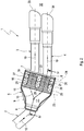
- Corresponding Fig. 1 includes an exhaust system 1, which can be used in an internal combustion engine for discharging exhaust gases and in particular can be arranged in a motor vehicle, at least one exhaust pipe 2 and two tail pipes 3 and 4, which are fluidly connected via a Y-manifold 5 with the exhaust pipe 2 are.
- the Y-manifold 5 is defined by connecting an inlet 6 to two outlets 7 and 8.
- two inlets (7,8) are connected to an outlet (6).
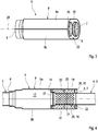
- it is characteristic of the Y-distributor that the inlet 6 on the one hand and the outlets 7, 8 on the other hand are located on opposite sides of a housing 9 of the Y-distributor 5. This gives a in Fig. 2 indicated by arrows 10 flow path in the Y-manifold 5 a Y-shape or Y-shaped configuration.
- the two tailpipes 3,4 are characterized in that they open directly into an environment 32.
- Each tail pipe 3, 4 thus has an outlet 33 or 34 which is open to the environment 32.
- the exhaust system 1 contains in the exhaust pipe 2 upstream of the Y-distributor 5 an exhaust gas purification device 11.
- This cleaning device 11 is preferably a particle filter, which will also be denoted by 11 below.
- the exhaust system 1 is then used in particular for use in an engine designed as a diesel engine. In principle, however, a use in a gasoline engine is conceivable.
- the exhaust system 1 is also equipped with an intermediate silencer 12, which has a housing 13 which has an inlet 14 and an outlet 15 for the exhaust pipe 2.
- an intermediate silencer 12 disposed between the particulate filter 11 and the Y-manifold 5 in the exhaust pipe 2.
- the Y-manifold 5 has a housing 9 having the inlet 6 and the two outlets 7 and 8.
- a partition wall 16 is arranged in the housing 9, that is, in the interior of the housing 9, a partition wall 16 is arranged.
- the partition 16 separates inside the housing 9 a distribution chamber 17 of a muffler chamber 18.
- the muffler chamber 18 is associated with both end pipes 3 and 4 together. This means that the sound-absorbing effect of the muffler chamber 18 benefits both tailpipes 3,4.
- the inlet 6 opens into the distribution chamber 17 a.
- the exhaust pipe 2 is connected to the inlet 6. Preference is given here a welded joint.
- the one tail pipe 3 is connected to the one outlet 7.
- the other tailpipe 4 is connected to the other outlet 8. Again, welded joints can be provided.
- the Y-distributor 5 has two connecting tubes 19, 20, which in each case fluidically connect an outlet 7, 8 to the distributor chamber 17.
- one connecting pipe 19 connects one outlet 7 to the distribution chamber 17, while the other connecting pipe 20 connects the other outlet 8 to the distribution chamber 17.
- Both connecting tubes 19, 20 pass through the muffler chamber 18.
- the two connecting tubes 19, 20 open into the distribution chamber 17 through the dividing wall 16.
- the two connecting tubes 19 are designed permeable transversely to the flow direction in each case for airborne sound.
- the two connecting pipes 19, 20 are perforated in order to allow the airborne sound transported in the exhaust gas to enter the silencer chamber 18. It is clear that in principle any other measure can be implemented around the respective connecting pipe 19,20 permeable to airborne sound. Instead of a plurality of individual passage openings, which in their entirety the respective, in the Figures 2 and 4 Formed with 21 designated perforation, and singular openings or slots or the like may be provided. Only a complete interruption of the respective connecting pipe 19,20 should be omitted in order to realize the lowest possible flow resistance.
- the two connecting pipes 19, 20 are fastened to the dividing wall 16.
- the partition wall 16 may be designed so that it has only two unspecified here openings, through which the connecting pipes 19,20 communicate with the distribution chamber 17. Likewise, a variant is possible in which the partition wall 16 is designed permeable even for airborne sound, so that airborne sound from the distribution chamber 17 can enter into the muffler chamber 18.
- the housing 9 is also equipped with an end wall 22.
- This end wall 22 limits the muffler chamber 18 on one of the partition 16 opposite side.
- the end wall 22 has the two outlets 7,8.
- the connecting pipes 19,20 are attached to the end wall 22.
- the two walls 16,22 are each in a plane 23 and 24.
- the two levels 23,24 are arranged parallel to each other in the context of usual tolerances.
- the two connecting pipes 19, 20 can be structurally integrated in the Y-distributor 5. Accordingly, then the tailpipes 3,4 are attached to the outlets 7,8 and to the connecting pipes 19,20.
- the connecting pipes 19, 20 each form an integral part of the respective end pipe 3, 4. Accordingly, then the tailpipes 3,4 are inserted with the preceding connecting pipes 19,20 through the outlets 7,8 through into the housing 9 and grown thereon accordingly.
- the muffler chamber 18 may be filled with an absorbing material 25 which absorbs airborne sound.
- absorption material 25 are all sufficiently heat-resistant, common sound absorbing materials.
- FIGS. 3 and 4 is removable, is preferred for the Y-distributor 5 and the housing 9, a half-shell construction, in which the housing 9 is assembled from two half-shells 9a and 9b.
- the two half-shells 9a, 9b lie against one another in a parting plane 26 and are fastened to one another in the region of this parting plane 26.
- Particularly useful is an embodiment in which the half shells 9a, 9b are designed as identical parts, ie as equal parts.
- the connecting pipes 19,20 are expediently designed as equal parts, provided that they are manufactured separately from the tailpipes 3,4 and installed in the Y-distributor 5.
- the embodiment shown here is advantageous, in which the two connecting tubes 19, 20 are spaced between their longitudinal ends towards the housing 9, namely at any point along the circumference of the respective connecting tube 19, 20.
- the two connecting tubes 19,20 relative to the housing 9 each have a distance 27 and 28, the is about the same size as a distance 29, which have the two connecting tubes 19,20 in said plane from each other.
- the average distance 29 deviates at most only about 20% from the two outer distances 27, 28, which are equal in size, in particular within the framework of the manufacturing tolerances.
- have the two connecting tubes 19,20 in a transverse to the in Fig. 2 level shown lying in the plane Fig. 4 Section shown IV-IV corresponds, from the housing 9 in each case a distance 30 and 31, respectively.
- These two distances 30,31 are the same within the scope of manufacturing tolerances. However, they are about half the size of the aforementioned distances 27,28 and 29.
- the two connecting tubes 19, 20 are guided through the muffler chamber 18 at a distance from one another. Furthermore, the two connecting tubes 19,20 expedient rectilinear designed. Preferably, they are passed through the muffler chamber 18 in parallel with each other.
- the end wall 22 may have two outwardly facing statements 35,36, each forming a respective outlet 7.8 enclosing ring collar.
- the respective connecting tube 19,20 is inserted from the inside into the respective extension 35,36.
- the respective tail pipe 3,4 is inserted from the outside into the respective connecting pipe 19,20.
- the respective end pipe 3,4 is supported on the end wall 22 via the associated connection pipe 19, 20 and the associated extension 35, 36.
- This design has the advantage that in the end only a single weld per tailpipe 3.4 must be attached in order to produce a tight connection between the respective tailpipe 4,5, the associated connecting pipe 19,20 and the end wall 22.
- the respective connecting pipe 19,20 in the region of the respective outlet 7,8 to the wall thickness of respective outflow tube 4.5 expanded outwardly to keep the flow resistance at the transition from the respective connecting pipe 19,20 in the associated tailpipe 4,5 as low as possible.
- the dividing wall 16 for the respective connecting pipe 19, 20 may have an intake 37, which encloses the associated opening in the manner of an annular collar and which projects into the muffler chamber 18.
- the respective connecting tube 19,20 is externally attached to this indentation 37.
- the combination of the Y-distributor 5 with the upstream particle filter 11 has proved to be particularly advantageous, since even in the particle filter 11 is already a sound attenuation, which makes it possible to design the muffler chamber 18 of the Y-distributor 5 is relatively small.
Landscapes
- Engineering & Computer Science (AREA)
- Chemical & Material Sciences (AREA)
- Combustion & Propulsion (AREA)
- Mechanical Engineering (AREA)
- General Engineering & Computer Science (AREA)
- Exhaust Silencers (AREA)
Claims (13)
- Système d'échappement pour un moteur à combustion interne, en particulier dans un véhicule automobile,- comprenant un tuyau de gaz d'échappement (2), qui devient, par l'intermédiaire d'un boîtier (9) deux tuyaux d'extrémité (3, 4),- dans lequel le boîtier (9) présente une chambre d'atténuation des bruits (18), qui est associée aux deux tuyaux d'extrémité (3,4) conjointement,- dans lequel le boîtier (9) est composé de deux demi-coques (9a, 9b),- dans lequel le tuyau de gaz d'échappement (2) est raccordé à une entrée (6) du boîtier (9), laquelle débouche dans une chambre de répartition (17),- dans lequel les tuyaux d'extrémité (4, 5) sont raccordés respectivement à une sortie (7, 8) du boîtier (9),- dans lequel chaque sortie (7, 8) est reliée fluidiquement par l'intermédiaire d'un tuyau de liaison (19, 20) à la chambre de répartition (17),- dans lequel le tuyau de liaison (19, 20) respectif traverse la chambre d'atténuation des bruits (18) et est configuré de manière à laisser passer les bruits transmis par l'air,- dans lequel le boîtier (9) forme un répartiteur en Y (5) de sorte que l'entrée (6) soit formée par les deux demi-coques (9a, 9b),caractérisé en ce- qu'une paroi de séparation (16) sépare, dans le boîtier (9), la chambre de répartition (17) de la chambre d'atténuation des bruits (18),- que le tuyau de liaison (19, 20) respectif débouche à travers la paroi de séparation (16) dans la chambre de répartition (17),- que le boîtier (9) présente une paroi d'extrémité (22), qui délimite la chambre d'amortissement des bruits (18) par rapport à la paroi de séparation (16) et qui présente des sorties (7, 8),- que les tuyaux de liaison (19, 20) sont montés dans la paroi de séparation (16) dans un siège coulissant, et/ou en ce que la paroi de séparation (16) est montée dans le boîtier (9) avec un siège coulissant.
- Système d'échappement selon la revendication 1,
caractérisé en ce
que l'entrée (6) fait face directement à la paroi de séparation (16) dans la chambre de répartition (17). - Système d'échappement selon la revendication 1 ou 2,
caractérisé en ce
que le tuyau de liaison (19, 20) respectif est perforé. - Système d'échappement selon l'une quelconque des revendications 1 à 3,
caractérisé en ce
que le tuyau de liaison (19, 20) respectif est fixé au niveau de la paroi de séparation (16). - Système d'échappement selon l'une quelconque des revendications 1 à 4,
caractérisé en ce
que les tuyaux de liaison (19, 20) sont fixés au niveau de la paroi d'extrémité (22). - Système d'échappement selon l'une quelconque des revendications 1 à 5,
caractérisé en ce
que la paroi d'extrémité (22) et la paroi de séparation (16) sont configurées de manière plane et sont disposées de manière parallèle l'une par rapport à l'autre dans le cadre de tolérances. - Système d'échappement selon l'une quelconque des revendications 1 à 6,
caractérisé en ce
que les tuyaux de liaison (19, 20) sont montés dans le boîtier (9) et les tuyaux d'extrémité (4, 5) sont installés par l'intermédiaire des sorties (7, 8) au niveau des tuyaux de liaison (19, 20). - Système d'échappement selon l'une quelconque des revendications 1 à 6,
caractérisé en ce
que les tuyaux de liaison (19, 20) sont formés d'un seul tenant au niveau des tuyaux d'extrémité (4, 5) et sont insérés dans le boîtier (9) en passant par les sorties (7, 8). - Système d'échappement selon l'une quelconque des revendications 1 à 8,
caractérisé en ce
que la chambre d'amortissement de bruits (18) est remplie d'un matériau à absorption (25) ayant un effet absorbant des bruits transmis par l'air. - Système d'échappement selon l'une quelconque des revendications 1 à 9,
caractérisé en ce
que la paroi de séparation (16) est configurée de manière à laisser passer les bruits transmis par l'air. - Système d'échappement selon l'une quelconque des revendications 1 à 10,
caractérisé en ce- que les tuyaux de liaison (19, 20) présentent, par rapport au boîtier (9), dans un premier plan, respectivement une première distance (27, 28), qui est supérieure ou égale d'un écart de 20% au maximum à une deuxième distance (29), que les deux tuyaux de liaison (19, 20) présentent dans le premier plan l'un de l'autre,- que les tuyaux de liaison (19, 20) présentent par rapport au boîtier (9), dans un deuxième plan s'étendant de manière transversale par rapport au premier plan, respectivement une troisième distance (30, 31), qui est égale à la moitié de la première distance (27, 28). - Système d'échappement selon l'une quelconque des revendications 1 à 11,
caractérisé en ce
que le tuyau de liaison (19, 20) respectif est élargi vers l'extérieure de l'épaisseur de paroi du tuyau d'extrémité (4, 5) respectif dans la zone de la sortie (7, 8) respective. - Répartiteur en Y pour un système d'échappement (1) selon l'une quelconque des revendications 1 à 12.
Applications Claiming Priority (1)
| Application Number | Priority Date | Filing Date | Title |
|---|---|---|---|
| DE200910049462 DE102009049462A1 (de) | 2009-10-15 | 2009-10-15 | Abgasanlage und Y-Verteiler |
Publications (2)
| Publication Number | Publication Date |
|---|---|
| EP2314834A1 EP2314834A1 (fr) | 2011-04-27 |
| EP2314834B1 true EP2314834B1 (fr) | 2017-03-01 |
Family
ID=43447926
Family Applications (1)
| Application Number | Title | Priority Date | Filing Date |
|---|---|---|---|
| EP10186402.3A Active EP2314834B1 (fr) | 2009-10-15 | 2010-10-04 | Système d'échappement avec répartiteur en forme Y |
Country Status (2)
| Country | Link |
|---|---|
| EP (1) | EP2314834B1 (fr) |
| DE (1) | DE102009049462A1 (fr) |
Families Citing this family (6)
| Publication number | Priority date | Publication date | Assignee | Title |
|---|---|---|---|---|
| US10100721B2 (en) | 2010-12-21 | 2018-10-16 | General Electric Company | Apparatus and system for directing exhaust gas flow |
| US20120151916A1 (en) * | 2010-12-21 | 2012-06-21 | Shishir Tiwari | Apparatus and system for directing exhaust gas flow |
| WO2019091542A1 (fr) * | 2017-11-07 | 2019-05-16 | Wärtsilä Finland Oy | Silencieux de gaz d'échappement pour un système d'échappement d'un moteur à combustion interne et système d'échappement |
| US11713700B2 (en) * | 2020-07-24 | 2023-08-01 | Mike's Pipes, Inc. | Method and apparatus for converting a vehicle from a dual-in, single-out exhaust system to a dual-in, dual-out exhaust system |
| DE102020005360A1 (de) | 2020-09-01 | 2022-03-03 | Daimler Ag | Katalysator für eln Kraftfahrzeug, sowle Kraftfahrzeug |
| DE102021119216A1 (de) * | 2021-07-26 | 2023-01-26 | Purem GmbH | Schalldämpfer |
Citations (1)
| Publication number | Priority date | Publication date | Assignee | Title |
|---|---|---|---|---|
| DE20115656U1 (de) * | 2001-09-22 | 2002-01-03 | Faurecia Abgastechnik GmbH, 90765 Fürth | Abgasanlage für ein motorbetriebenes Kraftfahrzeug |
Family Cites Families (5)
| Publication number | Priority date | Publication date | Assignee | Title |
|---|---|---|---|---|
| US2897909A (en) * | 1957-08-07 | 1959-08-04 | Abarth & Co | Silencer for motor vehicles |
| US2996139A (en) * | 1959-06-22 | 1961-08-15 | Runyen Mfg Company | Plenum type muffler |
| US5214253A (en) * | 1990-10-26 | 1993-05-25 | Houston Jr Richard G | Automotive exhaust system |
| JP2008095548A (ja) * | 2006-10-06 | 2008-04-24 | Yamaha Motor Co Ltd | エンジンの排気装置及び該排気装置を備えた自動二輪車 |
| DE102007007600A1 (de) * | 2007-02-13 | 2008-08-14 | J. Eberspächer GmbH & Co. KG | Schalldämpfer für eine Abgasanlage |
-
2009
- 2009-10-15 DE DE200910049462 patent/DE102009049462A1/de not_active Withdrawn
-
2010
- 2010-10-04 EP EP10186402.3A patent/EP2314834B1/fr active Active
Patent Citations (1)
| Publication number | Priority date | Publication date | Assignee | Title |
|---|---|---|---|---|
| DE20115656U1 (de) * | 2001-09-22 | 2002-01-03 | Faurecia Abgastechnik GmbH, 90765 Fürth | Abgasanlage für ein motorbetriebenes Kraftfahrzeug |
Also Published As
| Publication number | Publication date |
|---|---|
| EP2314834A1 (fr) | 2011-04-27 |
| DE102009049462A1 (de) | 2011-05-05 |
Similar Documents
| Publication | Publication Date | Title |
|---|---|---|
| EP2955344B1 (fr) | Silencieux | |
| EP0888493B1 (fr) | Systeme de silencieux | |
| EP2314834B1 (fr) | Système d'échappement avec répartiteur en forme Y | |
| EP2718550B1 (fr) | Silencieux et procédé de fabrication dudit silencieux | |
| EP2233708B2 (fr) | Dispositif de traitement des gaz d'échappement | |
| EP1914398B1 (fr) | Amortisseur de bruit secondaire de gaz d'échappement | |
| EP2362076B1 (fr) | Amortisseur de bruit | |
| DE2738600A1 (de) | Schalldaempfer | |
| EP1959106B2 (fr) | Silencieux pour un système d'échappement | |
| DE102010020064B4 (de) | Schalldämpferanordnung für eine insbesondere aufgeladene Kraftfahrzeug-Brennkraftmaschine | |
| EP3061931B1 (fr) | Systeme d'echappement de gaz d'un moteur a combustion interne | |
| EP3032063B1 (fr) | Tubulure d'échappement | |
| DE2930775C2 (de) | Absorptionsschalldämpfer für Abgase | |
| EP1788216A1 (fr) | Liaison intermédiaire pour dispositif d'échappement | |
| EP1798390B1 (fr) | Système d'échappement pour moteurs à combustion interne | |
| DE102010003301A1 (de) | Schalldämpfer | |
| EP1416148A2 (fr) | Pièce d'atténuation de bruit pour un tuyau d'admission d'air | |
| DE102018127116A1 (de) | Abgasschalldämpfervorrichtung | |
| EP2935854A1 (fr) | Élément guide d'air d'un système d'admission d'air frais | |
| EP1147305A1 (fr) | Dispositif d'admission presentant une section de conduite servant a amortir le bruit d'admission | |
| DE10128548A1 (de) | Abgasreinigungsvorrichtung für Brennkraftmaschinen | |
| DE102014114254A1 (de) | Passiver Schalldämpfer mit Helmholtz-Resonator für mehrflutige Abgasanlagen | |
| EP2788599A1 (fr) | Dispositif de silencieux | |
| EP1760280B1 (fr) | Système de traitement des gaz d'échappement | |
| EP3514342B1 (fr) | Amortisseur de bruit |
Legal Events
| Date | Code | Title | Description |
|---|---|---|---|
| PUAI | Public reference made under article 153(3) epc to a published international application that has entered the european phase |
Free format text: ORIGINAL CODE: 0009012 |
|
| AK | Designated contracting states |
Kind code of ref document: A1 Designated state(s): AL AT BE BG CH CY CZ DE DK EE ES FI FR GB GR HR HU IE IS IT LI LT LU LV MC MK MT NL NO PL PT RO RS SE SI SK SM TR |
|
| AX | Request for extension of the european patent |
Extension state: BA ME |
|
| 17P | Request for examination filed |
Effective date: 20111027 |
|
| RAP1 | Party data changed (applicant data changed or rights of an application transferred) |
Owner name: EBERSPAECHER EXHAUST TECHNOLOGY GMBH & CO. KG |
|
| 17Q | First examination report despatched |
Effective date: 20150107 |
|
| GRAP | Despatch of communication of intention to grant a patent |
Free format text: ORIGINAL CODE: EPIDOSNIGR1 |
|
| RIC1 | Information provided on ipc code assigned before grant |
Ipc: F01N 13/04 20100101ALI20160909BHEP Ipc: F01N 13/18 20100101ALI20160909BHEP Ipc: F01N 1/02 20060101AFI20160909BHEP |
|
| INTG | Intention to grant announced |
Effective date: 20161010 |
|
| GRAS | Grant fee paid |
Free format text: ORIGINAL CODE: EPIDOSNIGR3 |
|
| GRAA | (expected) grant |
Free format text: ORIGINAL CODE: 0009210 |
|
| AK | Designated contracting states |
Kind code of ref document: B1 Designated state(s): AL AT BE BG CH CY CZ DE DK EE ES FI FR GB GR HR HU IE IS IT LI LT LU LV MC MK MT NL NO PL PT RO RS SE SI SK SM TR |
|
| REG | Reference to a national code |
Ref country code: GB Ref legal event code: FG4D Free format text: NOT ENGLISH |
|
| REG | Reference to a national code |
Ref country code: CH Ref legal event code: EP Ref country code: AT Ref legal event code: REF Ref document number: 871632 Country of ref document: AT Kind code of ref document: T Effective date: 20170315 |
|
| REG | Reference to a national code |
Ref country code: IE Ref legal event code: FG4D Free format text: LANGUAGE OF EP DOCUMENT: GERMAN |
|
| REG | Reference to a national code |
Ref country code: DE Ref legal event code: R096 Ref document number: 502010013231 Country of ref document: DE |
|
| REG | Reference to a national code |
Ref country code: NL Ref legal event code: MP Effective date: 20170301 |
|
| REG | Reference to a national code |
Ref country code: LT Ref legal event code: MG4D |
|
| PG25 | Lapsed in a contracting state [announced via postgrant information from national office to epo] |
Ref country code: NO Free format text: LAPSE BECAUSE OF FAILURE TO SUBMIT A TRANSLATION OF THE DESCRIPTION OR TO PAY THE FEE WITHIN THE PRESCRIBED TIME-LIMIT Effective date: 20170601 Ref country code: HR Free format text: LAPSE BECAUSE OF FAILURE TO SUBMIT A TRANSLATION OF THE DESCRIPTION OR TO PAY THE FEE WITHIN THE PRESCRIBED TIME-LIMIT Effective date: 20170301 Ref country code: GR Free format text: LAPSE BECAUSE OF FAILURE TO SUBMIT A TRANSLATION OF THE DESCRIPTION OR TO PAY THE FEE WITHIN THE PRESCRIBED TIME-LIMIT Effective date: 20170602 Ref country code: LT Free format text: LAPSE BECAUSE OF FAILURE TO SUBMIT A TRANSLATION OF THE DESCRIPTION OR TO PAY THE FEE WITHIN THE PRESCRIBED TIME-LIMIT Effective date: 20170301 Ref country code: FI Free format text: LAPSE BECAUSE OF FAILURE TO SUBMIT A TRANSLATION OF THE DESCRIPTION OR TO PAY THE FEE WITHIN THE PRESCRIBED TIME-LIMIT Effective date: 20170301 |
|
| PG25 | Lapsed in a contracting state [announced via postgrant information from national office to epo] |
Ref country code: RS Free format text: LAPSE BECAUSE OF FAILURE TO SUBMIT A TRANSLATION OF THE DESCRIPTION OR TO PAY THE FEE WITHIN THE PRESCRIBED TIME-LIMIT Effective date: 20170301 Ref country code: LV Free format text: LAPSE BECAUSE OF FAILURE TO SUBMIT A TRANSLATION OF THE DESCRIPTION OR TO PAY THE FEE WITHIN THE PRESCRIBED TIME-LIMIT Effective date: 20170301 Ref country code: ES Free format text: LAPSE BECAUSE OF FAILURE TO SUBMIT A TRANSLATION OF THE DESCRIPTION OR TO PAY THE FEE WITHIN THE PRESCRIBED TIME-LIMIT Effective date: 20170301 Ref country code: BG Free format text: LAPSE BECAUSE OF FAILURE TO SUBMIT A TRANSLATION OF THE DESCRIPTION OR TO PAY THE FEE WITHIN THE PRESCRIBED TIME-LIMIT Effective date: 20170601 Ref country code: SE Free format text: LAPSE BECAUSE OF FAILURE TO SUBMIT A TRANSLATION OF THE DESCRIPTION OR TO PAY THE FEE WITHIN THE PRESCRIBED TIME-LIMIT Effective date: 20170301 |
|
| PG25 | Lapsed in a contracting state [announced via postgrant information from national office to epo] |
Ref country code: NL Free format text: LAPSE BECAUSE OF FAILURE TO SUBMIT A TRANSLATION OF THE DESCRIPTION OR TO PAY THE FEE WITHIN THE PRESCRIBED TIME-LIMIT Effective date: 20170301 |
|
| REG | Reference to a national code |
Ref country code: FR Ref legal event code: PLFP Year of fee payment: 8 |
|
| PG25 | Lapsed in a contracting state [announced via postgrant information from national office to epo] |
Ref country code: EE Free format text: LAPSE BECAUSE OF FAILURE TO SUBMIT A TRANSLATION OF THE DESCRIPTION OR TO PAY THE FEE WITHIN THE PRESCRIBED TIME-LIMIT Effective date: 20170301 Ref country code: SK Free format text: LAPSE BECAUSE OF FAILURE TO SUBMIT A TRANSLATION OF THE DESCRIPTION OR TO PAY THE FEE WITHIN THE PRESCRIBED TIME-LIMIT Effective date: 20170301 Ref country code: RO Free format text: LAPSE BECAUSE OF FAILURE TO SUBMIT A TRANSLATION OF THE DESCRIPTION OR TO PAY THE FEE WITHIN THE PRESCRIBED TIME-LIMIT Effective date: 20170301 Ref country code: CZ Free format text: LAPSE BECAUSE OF FAILURE TO SUBMIT A TRANSLATION OF THE DESCRIPTION OR TO PAY THE FEE WITHIN THE PRESCRIBED TIME-LIMIT Effective date: 20170301 |
|
| PG25 | Lapsed in a contracting state [announced via postgrant information from national office to epo] |
Ref country code: IS Free format text: LAPSE BECAUSE OF FAILURE TO SUBMIT A TRANSLATION OF THE DESCRIPTION OR TO PAY THE FEE WITHIN THE PRESCRIBED TIME-LIMIT Effective date: 20170701 Ref country code: PL Free format text: LAPSE BECAUSE OF FAILURE TO SUBMIT A TRANSLATION OF THE DESCRIPTION OR TO PAY THE FEE WITHIN THE PRESCRIBED TIME-LIMIT Effective date: 20170301 Ref country code: PT Free format text: LAPSE BECAUSE OF FAILURE TO SUBMIT A TRANSLATION OF THE DESCRIPTION OR TO PAY THE FEE WITHIN THE PRESCRIBED TIME-LIMIT Effective date: 20170703 Ref country code: SM Free format text: LAPSE BECAUSE OF FAILURE TO SUBMIT A TRANSLATION OF THE DESCRIPTION OR TO PAY THE FEE WITHIN THE PRESCRIBED TIME-LIMIT Effective date: 20170301 |
|
| REG | Reference to a national code |
Ref country code: DE Ref legal event code: R097 Ref document number: 502010013231 Country of ref document: DE |
|
| PLBE | No opposition filed within time limit |
Free format text: ORIGINAL CODE: 0009261 |
|
| STAA | Information on the status of an ep patent application or granted ep patent |
Free format text: STATUS: NO OPPOSITION FILED WITHIN TIME LIMIT |
|
| PG25 | Lapsed in a contracting state [announced via postgrant information from national office to epo] |
Ref country code: DK Free format text: LAPSE BECAUSE OF FAILURE TO SUBMIT A TRANSLATION OF THE DESCRIPTION OR TO PAY THE FEE WITHIN THE PRESCRIBED TIME-LIMIT Effective date: 20170301 |
|
| 26N | No opposition filed |
Effective date: 20171204 |
|
| PG25 | Lapsed in a contracting state [announced via postgrant information from national office to epo] |
Ref country code: SI Free format text: LAPSE BECAUSE OF FAILURE TO SUBMIT A TRANSLATION OF THE DESCRIPTION OR TO PAY THE FEE WITHIN THE PRESCRIBED TIME-LIMIT Effective date: 20170301 |
|
| PGFP | Annual fee paid to national office [announced via postgrant information from national office to epo] |
Ref country code: IT Payment date: 20171020 Year of fee payment: 8 |
|
| PG25 | Lapsed in a contracting state [announced via postgrant information from national office to epo] |
Ref country code: MC Free format text: LAPSE BECAUSE OF FAILURE TO SUBMIT A TRANSLATION OF THE DESCRIPTION OR TO PAY THE FEE WITHIN THE PRESCRIBED TIME-LIMIT Effective date: 20170301 |
|
| REG | Reference to a national code |
Ref country code: CH Ref legal event code: PL |
|
| GBPC | Gb: european patent ceased through non-payment of renewal fee |
Effective date: 20171004 |
|
| REG | Reference to a national code |
Ref country code: IE Ref legal event code: MM4A |
|
| PG25 | Lapsed in a contracting state [announced via postgrant information from national office to epo] |
Ref country code: GB Free format text: LAPSE BECAUSE OF NON-PAYMENT OF DUE FEES Effective date: 20171004 Ref country code: LI Free format text: LAPSE BECAUSE OF NON-PAYMENT OF DUE FEES Effective date: 20171031 Ref country code: CH Free format text: LAPSE BECAUSE OF NON-PAYMENT OF DUE FEES Effective date: 20171031 Ref country code: LU Free format text: LAPSE BECAUSE OF NON-PAYMENT OF DUE FEES Effective date: 20171004 |
|
| REG | Reference to a national code |
Ref country code: BE Ref legal event code: MM Effective date: 20171031 |
|
| PG25 | Lapsed in a contracting state [announced via postgrant information from national office to epo] |
Ref country code: BE Free format text: LAPSE BECAUSE OF NON-PAYMENT OF DUE FEES Effective date: 20171031 |
|
| PG25 | Lapsed in a contracting state [announced via postgrant information from national office to epo] |
Ref country code: MT Free format text: LAPSE BECAUSE OF FAILURE TO SUBMIT A TRANSLATION OF THE DESCRIPTION OR TO PAY THE FEE WITHIN THE PRESCRIBED TIME-LIMIT Effective date: 20170301 |
|
| REG | Reference to a national code |
Ref country code: FR Ref legal event code: PLFP Year of fee payment: 9 |
|
| PG25 | Lapsed in a contracting state [announced via postgrant information from national office to epo] |
Ref country code: IE Free format text: LAPSE BECAUSE OF NON-PAYMENT OF DUE FEES Effective date: 20171004 |
|
| REG | Reference to a national code |
Ref country code: AT Ref legal event code: MM01 Ref document number: 871632 Country of ref document: AT Kind code of ref document: T Effective date: 20171004 |
|
| PG25 | Lapsed in a contracting state [announced via postgrant information from national office to epo] |
Ref country code: AT Free format text: LAPSE BECAUSE OF NON-PAYMENT OF DUE FEES Effective date: 20171004 |
|
| PG25 | Lapsed in a contracting state [announced via postgrant information from national office to epo] |
Ref country code: HU Free format text: LAPSE BECAUSE OF FAILURE TO SUBMIT A TRANSLATION OF THE DESCRIPTION OR TO PAY THE FEE WITHIN THE PRESCRIBED TIME-LIMIT; INVALID AB INITIO Effective date: 20101004 |
|
| PG25 | Lapsed in a contracting state [announced via postgrant information from national office to epo] |
Ref country code: CY Free format text: LAPSE BECAUSE OF NON-PAYMENT OF DUE FEES Effective date: 20170301 Ref country code: IT Free format text: LAPSE BECAUSE OF NON-PAYMENT OF DUE FEES Effective date: 20181004 |
|
| PG25 | Lapsed in a contracting state [announced via postgrant information from national office to epo] |
Ref country code: MK Free format text: LAPSE BECAUSE OF FAILURE TO SUBMIT A TRANSLATION OF THE DESCRIPTION OR TO PAY THE FEE WITHIN THE PRESCRIBED TIME-LIMIT Effective date: 20170301 |
|
| PG25 | Lapsed in a contracting state [announced via postgrant information from national office to epo] |
Ref country code: TR Free format text: LAPSE BECAUSE OF FAILURE TO SUBMIT A TRANSLATION OF THE DESCRIPTION OR TO PAY THE FEE WITHIN THE PRESCRIBED TIME-LIMIT Effective date: 20170301 |
|
| PG25 | Lapsed in a contracting state [announced via postgrant information from national office to epo] |
Ref country code: AL Free format text: LAPSE BECAUSE OF FAILURE TO SUBMIT A TRANSLATION OF THE DESCRIPTION OR TO PAY THE FEE WITHIN THE PRESCRIBED TIME-LIMIT Effective date: 20170301 |
|
| REG | Reference to a national code |
Ref country code: DE Ref legal event code: R081 Ref document number: 502010013231 Country of ref document: DE Owner name: PUREM GMBH, DE Free format text: FORMER OWNER: EBERSPAECHER EXHAUST TECHNOLOGY GMBH & CO. KG, 66539 NEUNKIRCHEN, DE |
|
| PGFP | Annual fee paid to national office [announced via postgrant information from national office to epo] |
Ref country code: DE Payment date: 20251020 Year of fee payment: 16 |
|
| PGFP | Annual fee paid to national office [announced via postgrant information from national office to epo] |
Ref country code: FR Payment date: 20251029 Year of fee payment: 16 |