EP2317091A1 - Exhaust purification system for internal combustion engine - Google Patents
Exhaust purification system for internal combustion engine Download PDFInfo
- Publication number
- EP2317091A1 EP2317091A1 EP10189618A EP10189618A EP2317091A1 EP 2317091 A1 EP2317091 A1 EP 2317091A1 EP 10189618 A EP10189618 A EP 10189618A EP 10189618 A EP10189618 A EP 10189618A EP 2317091 A1 EP2317091 A1 EP 2317091A1
- Authority
- EP
- European Patent Office
- Prior art keywords
- urea
- amount
- slip
- reducing agent
- selective reduction
- Prior art date
- Legal status (The legal status is an assumption and is not a legal conclusion. Google has not performed a legal analysis and makes no representation as to the accuracy of the status listed.)
- Granted
Links
Images


Classifications
-
- F—MECHANICAL ENGINEERING; LIGHTING; HEATING; WEAPONS; BLASTING
- F01—MACHINES OR ENGINES IN GENERAL; ENGINE PLANTS IN GENERAL; STEAM ENGINES
- F01N—GAS-FLOW SILENCERS OR EXHAUST APPARATUS FOR MACHINES OR ENGINES IN GENERAL; GAS-FLOW SILENCERS OR EXHAUST APPARATUS FOR INTERNAL-COMBUSTION ENGINES
- F01N3/00—Exhaust or silencing apparatus having means for purifying, rendering innocuous, or otherwise treating exhaust
- F01N3/08—Exhaust or silencing apparatus having means for purifying, rendering innocuous, or otherwise treating exhaust for rendering innocuous
- F01N3/10—Exhaust or silencing apparatus having means for purifying, rendering innocuous, or otherwise treating exhaust for rendering innocuous by thermal or catalytic conversion of noxious components of exhaust
- F01N3/18—Exhaust or silencing apparatus having means for purifying, rendering innocuous, or otherwise treating exhaust for rendering innocuous by thermal or catalytic conversion of noxious components of exhaust characterised by methods of operation; Control
- F01N3/20—Exhaust or silencing apparatus having means for purifying, rendering innocuous, or otherwise treating exhaust for rendering innocuous by thermal or catalytic conversion of noxious components of exhaust characterised by methods of operation; Control specially adapted for catalytic conversion
- F01N3/206—Adding periodically or continuously substances to exhaust gases for promoting purification, e.g. catalytic material in liquid form, NOx reducing agents
- F01N3/208—Control of selective catalytic reduction [SCR], e.g. by adjusting the dosing of reducing agent
-
- F—MECHANICAL ENGINEERING; LIGHTING; HEATING; WEAPONS; BLASTING
- F01—MACHINES OR ENGINES IN GENERAL; ENGINE PLANTS IN GENERAL; STEAM ENGINES
- F01N—GAS-FLOW SILENCERS OR EXHAUST APPARATUS FOR MACHINES OR ENGINES IN GENERAL; GAS-FLOW SILENCERS OR EXHAUST APPARATUS FOR INTERNAL-COMBUSTION ENGINES
- F01N2560/00—Exhaust systems with means for detecting or measuring exhaust gas components or characteristics
- F01N2560/02—Exhaust systems with means for detecting or measuring exhaust gas components or characteristics the means being an exhaust gas sensor
- F01N2560/021—Exhaust systems with means for detecting or measuring exhaust gas components or characteristics the means being an exhaust gas sensor for measuring or detecting ammonia NH3
-
- F—MECHANICAL ENGINEERING; LIGHTING; HEATING; WEAPONS; BLASTING
- F01—MACHINES OR ENGINES IN GENERAL; ENGINE PLANTS IN GENERAL; STEAM ENGINES
- F01N—GAS-FLOW SILENCERS OR EXHAUST APPARATUS FOR MACHINES OR ENGINES IN GENERAL; GAS-FLOW SILENCERS OR EXHAUST APPARATUS FOR INTERNAL-COMBUSTION ENGINES
- F01N2900/00—Details of electrical control or of the monitoring of the exhaust gas treating apparatus
- F01N2900/04—Methods of control or diagnosing
- F01N2900/0411—Methods of control or diagnosing using a feed-forward control
-
- F—MECHANICAL ENGINEERING; LIGHTING; HEATING; WEAPONS; BLASTING
- F01—MACHINES OR ENGINES IN GENERAL; ENGINE PLANTS IN GENERAL; STEAM ENGINES
- F01N—GAS-FLOW SILENCERS OR EXHAUST APPARATUS FOR MACHINES OR ENGINES IN GENERAL; GAS-FLOW SILENCERS OR EXHAUST APPARATUS FOR INTERNAL-COMBUSTION ENGINES
- F01N2900/00—Details of electrical control or of the monitoring of the exhaust gas treating apparatus
- F01N2900/06—Parameters used for exhaust control or diagnosing
- F01N2900/14—Parameters used for exhaust control or diagnosing said parameters being related to the exhaust gas
- F01N2900/1402—Exhaust gas composition
-
- F—MECHANICAL ENGINEERING; LIGHTING; HEATING; WEAPONS; BLASTING
- F01—MACHINES OR ENGINES IN GENERAL; ENGINE PLANTS IN GENERAL; STEAM ENGINES
- F01N—GAS-FLOW SILENCERS OR EXHAUST APPARATUS FOR MACHINES OR ENGINES IN GENERAL; GAS-FLOW SILENCERS OR EXHAUST APPARATUS FOR INTERNAL-COMBUSTION ENGINES
- F01N2900/00—Details of electrical control or of the monitoring of the exhaust gas treating apparatus
- F01N2900/06—Parameters used for exhaust control or diagnosing
- F01N2900/16—Parameters used for exhaust control or diagnosing said parameters being related to the exhaust apparatus, e.g. particulate filter or catalyst
- F01N2900/1616—NH3-slip from catalyst
-
- F—MECHANICAL ENGINEERING; LIGHTING; HEATING; WEAPONS; BLASTING
- F01—MACHINES OR ENGINES IN GENERAL; ENGINE PLANTS IN GENERAL; STEAM ENGINES
- F01N—GAS-FLOW SILENCERS OR EXHAUST APPARATUS FOR MACHINES OR ENGINES IN GENERAL; GAS-FLOW SILENCERS OR EXHAUST APPARATUS FOR INTERNAL-COMBUSTION ENGINES
- F01N2900/00—Details of electrical control or of the monitoring of the exhaust gas treating apparatus
- F01N2900/06—Parameters used for exhaust control or diagnosing
- F01N2900/16—Parameters used for exhaust control or diagnosing said parameters being related to the exhaust apparatus, e.g. particulate filter or catalyst
- F01N2900/1622—Catalyst reducing agent absorption capacity or consumption amount
-
- Y—GENERAL TAGGING OF NEW TECHNOLOGICAL DEVELOPMENTS; GENERAL TAGGING OF CROSS-SECTIONAL TECHNOLOGIES SPANNING OVER SEVERAL SECTIONS OF THE IPC; TECHNICAL SUBJECTS COVERED BY FORMER USPC CROSS-REFERENCE ART COLLECTIONS [XRACs] AND DIGESTS
- Y02—TECHNOLOGIES OR APPLICATIONS FOR MITIGATION OR ADAPTATION AGAINST CLIMATE CHANGE
- Y02T—CLIMATE CHANGE MITIGATION TECHNOLOGIES RELATED TO TRANSPORTATION
- Y02T10/00—Road transport of goods or passengers
- Y02T10/10—Internal combustion engine [ICE] based vehicles
- Y02T10/12—Improving ICE efficiencies
Definitions
- the present invention relates to an exhaust purification system for an internal combustion engine, and particularly relates to an exhaust purification system for an internal combustion engine equipped with a selective reduction catalyst that reduces NOx in the exhaust under the presence of a reducing agent.
- a system in which a selective reduction catalyst that selectively reduces NOx in the exhaust by way of a reducing agent is provided in an exhaust channel.
- a selective reduction catalyst that selectively reduces NOx in the exhaust by way of a reducing agent is provided in an exhaust channel.
- urea water is supplied from an upstream side of the selective reduction catalyst, ammonia is generated by thermal decomposition or hydrolysis of this urea water by the heat of the exhaust, and the NOx in the exhaust is selectively reduced by this ammonia.
- a system has also been proposed that generates ammonia by heating a compound of ammonia such as ammonia carbide, and directly adds this ammonia.
- a system of urea addition type will be explained hereinafter.
- Patent Document 1 With the exhaust purification system disclosed in Japanese Unexamined Patent Application Publication No. 2004-100700 (hereinafter referred to as Patent Document 1), the NOx amount on a downstream side of the selective reduction catalyst is detected by a NOx sensor, and the composition of the exhaust flowing into the selective reduction catalyst, more specifically, the ratio of NO and NO 2 , is estimated from the output value of this NOx sensor and the operating state of the internal combustion engine. Furthermore, based on this composition of the exhaust, the NOx purification rate of the selective reduction catalyst is estimated and the injection amount of urea water is controlled.
- Patent Document 2 the temperature of the catalyst is detected as an amount relating to the NOx purification rate of the selective reduction catalyst, and the injection amount of urea water is controlled based on this temperature.
- the NOx reduction rate of the selective reduction catalyst changes not only by the above such composition of the exhaust and temperature of the selective reduction catalyst, but also according to the degradation state of the selective reduction catalyst.
- FIG. 19 is a schematic diagram showing a configuration of a conventional exhaust purification system 80.
- an oxidation catalyst 83 As shown in FIG. 19 , an oxidation catalyst 83, a urea injection valve 85 that injects urea water as a reducing agent that is stored in a urea tank 84 into an exhaust channel 82, and a selective reduction catalyst 86 that reduces NOx in the exhaust under the presence of ammonia are provided in sequence from an upstream side to a downstream side in the exhaust channel 82 of an engine 81.
- a temperature sensor 87 that detects a temperature of the selective reduction catalyst 86 and a NOx sensor 88 that detects a NOx amount on a downstream side of the selective reduction catalyst 86 are provided as sensors for observing the purification performance of the selective reduction catalyst.
- the NOx amount of exhaust discharged from the engine 81 is estimated by way of a map set in advance, and the injection amount of urea water from the urea injection valve 85 is determined based on this NOx amount and the catalyst temperature detected by the temperature sensor 87.
- the degradation state of the selective reduction catalyst 86 can be estimated based on a difference between an output value of the NOx sensor 88 and the NOx amount of exhaust thus estimated.
- the injection amount of urea water is corrected in accordance with the degradation state of the selective reduction catalyst 86 estimated in the above way.
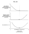
- FIG. 20 shows relationships between the NOx amount and ammonia amount in the exhaust downstream of the selective reduction catalyst and the output value of the NOx sensor for the aforementioned conventional exhaust purification system. More specifically, FIG. 20 shows, in sequence from the upper graph, relationships between the NOx amount of exhaust downstream of the selective reduction catalyst, the ammonia amount of exhaust downstream of the selective reduction catalyst, and the output value of the NOx sensor, with the urea water injection amount.
- the NOx purification rate of the selective reduction catalyst rises due to the ammonia generated in the selective reduction catalyst also increasing.
- the NOx amount downstream of the selective reduction catalyst decreases accompanying the injection amount of urea water increasing, as shown in FIG. 20 .
- the NOx amount is substantially constant irrespective of the urea water injection amount. In other words, urea water of the amount exceeding the star indicates being surplus relative to that reducing the NOx generated.
- the ammonia generated from the urea water that is surplus is not consumed in the reduction of NOx, and is either stored in the selective reduction catalyst or discharged to downstream of the selective reduction catalyst. Therefore, as shown in FIG. 20 , the ammonia amount of exhaust downstream of the selective reduction catalyst increases, when exceeding the injection amount of urea water indicated by the star.
- reducing agent slip reducing agent discharging from the selective reduction catalyst to the downstream side thereof in this way
- ammonia slip in a case of using ammonia as the reducing agent in particular, is referred to as "ammonia slip".
- the urea water injection amount indicated by the star in FIG. 20 can both minimize the NOx amount and ammonia amount in the above way, it is the optimum injection amount for this exhaust purification system.
- the output value of the NOx sensor shows a downward convex characteristic in which the output value of this optimum injection amount is a minimum point.
- the selective reduction catalyst in addition to the ability to reduce NOx under the presence of ammonia in the above way, the selective reduction catalyst has the ability to store ammonia.
- FIG. 21 is a graph showing a relationship between a storage rate and NOx purification rate of the selective reduction catalyst.
- the storage rate refers to a proportion of the ammonia amount stored in the selective reduction catalyst relative to the maximum value thereof.
- the NOx purification rate of the selective reduction catalyst has a characteristic of increasing with higher storage rates. Therefore, in suppressing the occurrence of ammonia slip while maintaining the NOx purification to be high, it is desirable to control the storage rate of the selective reduction catalyst to the maximum value with high precision.
- NOx sensors have the aforementioned such characteristics, it is difficult to continuously control the storage rate to the maximum value while suppressing the occurrence of ammonia slip, and thus the control system may also fail.
- the occurrence of excessive ammonia slip is suppressed in exchange for a decline in NOx purification rate, by controlling the storage rate to approximately 15 to 30%.
- the present invention was made taking into account of the aforementioned points, and provides an exhaust purification system for an internal combustion engine provided with a selective reduction catalyst, the system being able to continuously maintain the NOx purification rate of the selective reduction catalyst to be high, while suppressing the occurrence of reducing agent slip.
- the present invention provides an exhaust purification system for an internal combustion engine (e.g., the exhaust purification system 2 described later) equipped with a selective reduction catalyst (e.g., the selective reduction catalyst 23 described later) provided in an exhaust channel (e.g., the exhaust channel 11 described later) of the internal combustion engine (e.g., the engine 1 described later) that reduces NOx in exhaust flow through the exhaust channel under the presence of a reducing agent (e.g., the ammonia described later), and a reducing agent supply means (e.g., the urea injection device 25 described later) that supplies reducing agent or an additive (e.g., the urea water described later) serving as a source of the reducing agent.
- a selective reduction catalyst e.g., the selective reduction catalyst 23 described later
- an exhaust channel e.g., the exhaust channel 11 described later
- a reducing agent supply means e.g., the urea injection device 25 described later
- reducing agent or an additive e.g., the ure
- the exhaust purification system includes: a reducing agent detection means (e.g., the ammonia sensor 26 described later) for detecting a reducing agent amount or reducing agent concentration of exhaust in the exhaust channel on a downstream side of the selective reduction catalyst; a slip determination means (e.g., the slip determination portion 34) for determining (F NH3_SLIP ) an occurrence of reducing agent slip in the selective reduction catalyst based on an output value (NH3 CONS ) of the reducing agent detection means; a storage amount estimation means (e.g., the state estimation unit 35 described later) for calculating an estimated value (ST UREA ) of a storage amount, with an amount of reducing agent stored in the selective reduction catalyst as the storage amount; and a supply amount determination means (e.g., the reference injection amount calculating portion 31, switching injection amount calculating portion 32, and adder 33 described later) for determining a supply amount (G UREA ) of the reducing agent supply means, in which the supply amount determination means determines a supply amount by decreasing in amount
- the reference supply amount for the supply amount of reducing agent or additive from the reducing agent supply means is calculated based on a parameter correlating to an operating state of the internal combustion engine.
- the supply amount is determined by reducing in amount, relative to the reference supply amount calculated according to the operating state of the internal combustion engine, in response to having determined that reducing agent slip of the selective reduction catalyst has occurred, and increasing in amount in response to the estimated value of the storage amount having fallen below the switch determination value.
- the output characteristics vary due to components other than the reducing agent, such as O 2 and H 2 O in exhaust.
- the supply amount may deviate from the optimum amount due to unexpected variation in the output characteristics of the reducing agent detection means, and may cause a decline in the NOx purification rate and the occurrence of excessive reducing agent slip.
- the slip determination means determines the existence of the occurrence of reducing agent slip, i.e. the existence of reducing agent in exhaust on a downstream side of the selective reduction catalyst, based on the output value of the reducing agent detection means.
- the determination results of such an existence of reducing agent are considered not to be greatly influenced by gain variation in the aforementioned such reducing agent detection means. Therefore, according to the present invention, it is possible to determine the supply amount without being affected by the gain variation of the reducing agent detection means.
- the exhaust purification system it is preferable for the exhaust purification system to further include a storage capacity estimation means (e.g., the state estimation unit 35 and the storage capacity correction unit 36 described later) for calculating an estimated value (ST UREA_MAX ) of a storage capacity, with an amount of reducing agent that can be stored by the selective reduction catalyst as the storage capacity, in which the switch determination value (ST UREA_SW ) is set based on the estimated value (ST UREA_MAX ) of the storage capacity.
- a storage capacity estimation means e.g., the state estimation unit 35 and the storage capacity correction unit 36 described later
- the estimated value of the storage capacity which is the amount of reducing agent that can be stored by the selective reduction catalyst, i.e. the maximum value of the storage amount, is calculated, and the above-mentioned switch determination value is set based on this estimated value of the storage capacity.
- a slip estimation means e.g., the state estimation unit 35 described later
- the estimated value of the storage capacity is corrected according to the difference between the occurrence time of reducing agent slip determined based on the output value of the reducing agent detection means and the occurrence time of reducing agent slip determined based on the estimated value of the storage amount.
- the present invention provides an exhaust purification system for an internal combustion engine (e.g., the exhaust purification system 2 described later) equipped with a selective reduction catalyst (e.g., the selective reduction catalyst 23 described later) provided in an exhaust channel (e.g., the exhaust channel 11 described later) of the internal combustion engine (e.g., the engine 1 described later) that reduces NOx in exhaust flow through the exhaust channel under the presence of a reducing agent (e.g., the ammonia described later), and a reducing agent supply means (e.g., the urea injection device 25 described later) that supplies reducing agent or an additive (e.g., the urea water described later) serving as a source of the reducing agent.
- a selective reduction catalyst e.g., the selective reduction catalyst 23 described later
- an exhaust channel e.g., the exhaust channel 11 described later
- a reducing agent supply means e.g., the urea injection device 25 described later
- reducing agent or an additive e.g., the ure
- the exhaust purification system includes: a reducing agent detection means (e.g., the ammonia sensor 26 described later) for detecting a reducing agent amount or reducing agent concentration of exhaust in the exhaust channel on a downstream side of the selective reduction catalyst; a storage amount estimation means (e.g., the state estimation unit 35 described later) for calculating an estimated value (ST UREA ) of a storage amount, with an amount of reducing agent stored in the selective reduction catalyst as the storage amount; a storage capacity estimation means (e.g., the state estimation unit 35 and the storage capacity correction unit 36 described later) for calculating an estimated value (ST UREA_MAx ) of a storage capacity, with an amount of reducing agent that can be stored by the selective reduction catalyst as the storage capacity; a slip determination means (e.g., the slip determination portion 34 described later) for determining (F NH3_SLIP ) an occurrence of reducing agent slip in the selective reduction catalyst based on an output value (NH3 CONS ) of the reducing agent detection means; a slip
- the supply amount of the reducing agent or additive from the reducing agent supply means is determined based on a parameter correlating to the operating state of the internal combustion engine, the estimated value of the storage amount, and the estimated value of the storage capacity.
- the estimated value of the storage capacity is corrected according to the difference between the occurrence time of reducing agent slip determined based on the output value of the reducing agent detection means and the occurrence time of reducing agent slip determined based on the estimated value of the storage amount.
- a plurality of weighting functions e.g., the weighting functions W i described later
- a plurality of correction values e.g., the local correction values KVNS i described later
- the storage capacity estimation means to update the plurality of correction values based on a difference between an occurrence time of reducing agent slip determined by way of the slip determination means and an occurrence time of reducing agent slip determined by way of the slip estimation means, to set a sum total of products of the plurality of correction values thus updated and values of the plurality of weighting functions according to the temperature of the selective reduction catalyst as a correction coefficient (e.g., the storage capacity correction value KVNS), and to correct the estimated value of the storage capacity based on the correction coefficient.
- a correction coefficient e.g., the storage capacity correction value KVNS
- the plurality of correction values set for the plurality of regions of the temperature of the selective reduction catalyst is updated based on the difference between the occurrence time of reducing agent slip determined by the slip determination means and the occurrence time of reducing agent slip determined by way of the slip estimation means. Then, a sum total of products of values of the plurality of weighting functions according to the temperature of the selective reduction catalyst and the above-mentioned plurality of correction values is set as a correction coefficient, and the estimated value of the storage capacity is corrected based on this correction coefficient. With this, it is possible to adaptively correct the correction value of the storage capacity so that the time for which reducing agent slip actually occurred and the estimated time for which reducing agent slip occurred are in agreement.
- the exhaust purification system it is preferable for the exhaust purification system to further include a catalyst degradation determination means (e.g., the catalyst degradation determination unit 37 described later) for determining degradation of the selective reduction catalyst based on at least any of the estimated value (ST UREA_MAX ) of the storage capacity, the plurality of correction values (KVNS i ), and the correction coefficient (KVNS).
- a catalyst degradation determination means e.g., the catalyst degradation determination unit 37 described later
- the exhaust purification system to further include a catalyst degradation determination means for determining degradation of the selective reduction catalyst based on at least any of the estimated value (ST UREA_MAX ) of the storage capacity, the plurality of correction values (KVNS i ), and the correction coefficient (KVNS).
- FIG. 1 is a schematic diagraph showing configurations of an internal combustion engine (hereinafter referred to as "engine") 1 and an exhaust purification system 2 thereof according to one embodiment of the present invention.
- the engine 1 is a gasoline engine of lean-burn operating type or diesel engine, and is mounted in a vehicle, which is not illustrated.
- the exhaust purification system 2 is configured to contain a selective reduction catalyst 23 that is provided in an exhaust channel 11 of the engine 1 and purifies nitrogen oxides (hereinafter referred to as "NOx") in exhaust flowing through this exhaust channel 11 under the presence of ammonia as a reducing agent, a urea injection device 25 that supplies urea water, which is a source of the reducing agent, into the exhaust channel 11 on an upstream side of the selective reduction catalyst 23, and an electronic control unit (hereinafter referred to as "ECU”) 3.
- an oxidation catalyst 21 and a slip suppressing catalyst 24 are provided in the exhaust channel 11.
- the urea injection device 25 includes a urea tank 251 and a urea injection valve 253.
- the urea tank 251 stores urea water, and is connected to the urea injection valve 253 a urea supply pipe 254 and a urea pump, which is not illustrated.
- a urea level sensor 255 is provided to this urea tank 251. This urea level sensor 255 detects the water level of the urea water in the urea tank 251, and outputs a detection signal substantially proportional to this water level to the ECU 3.
- the urea injection valve 253 is connected to the ECU 3, operates according to a control signal from the ECU 3, and injects urea water into the exhaust channel 11 in accordance with this control signal. In other words, urea injection control is executed.
- the oxidation catalyst 21 is provided more on an upstream side in the exhaust channel 11 than the urea selective reduction catalyst 23 and the urea injection valve 253, and converts a portion of NO in the exhaust to NO 2 thereby promoting reduction of NOx in the selective reduction catalyst 23.
- the selective reduction catalyst 23 selectively reduces NOx in exhaust under an atmosphere in which a reducing agent such as ammonia is present. More specifically, when urea water is injected by the urea injection device 25, this urea water is thermally decomposed or hydrolyzed by the heat of exhaust, and ammonia is produced. The ammonia thus produced is supplied to the selective reduction catalyst 23, and NOx in the exhaust is selectively reduced by this ammonia.
- a reducing agent such as ammonia
- This selective reduction catalyst 23 has a function of reducing NOx in exhaust by the ammonia produced from the urea water, as well as having a function of storing only a predetermined amount of the ammonia thus generated.
- the ammonia amount stored in the selective reduction catalyst 23 is defined as a storage amount
- the ammonia amount that can be stored in the selective reduction catalyst 23 is defined as a storage capacity.
- the ammonia stored in this way is also consumed as appropriate in the reduction of NOx in the exhaust.
- the NOx purification rate of the selective reduction catalyst 23 increases in accordance with the storage amount increasing.
- the storage amount reaches the storage capacity and the selective reduction catalyst 23 enters a saturated state, although the NOx purification rate also reaches a maximum value, ammonia slip occurs in which the ammonia not contributing to the reduction of NOx and has become surplus is discharged to a downstream side of the selective reduction catalyst 23.
- the slip suppressing catalyst 24 is provided in the exhaust channel 11 on a downstream side of the selective reduction catalyst 23, and in a case of ammonia slip in the selective reduction catalyst 23 having occurred, suppresses the ammonia having slipped from being discharged outside the system.
- an oxidation catalyst that oxidizes ammonia having slipped from the selective reduction catalyst 23 to break down into N 2 and H 2 O, a selective reduction catalyst that stores the ammonia having slipped, or the like can be used as this slip suppressing catalyst 24.
- a crank angle position sensor 14 In addition to the ammonia sensor 26, the catalyst temperature sensor 27, and the NOx sensor 28, a crank angle position sensor 14, an accelerator opening sensor 15, a urea remaining amount warning light 16, and a catalyst degradation warning light 17 are connected to the ECU 3.
- the ammonia sensor 26 detects the ammonia concentration NH3 CONS of exhaust in the exhaust channel 11 between the selective reduction catalyst 23 and the slip suppressing catalyst 24, and supplies a detection signal substantially proportional to the ammonia concentration NH3 CONS thus detected to the ECU 3.
- the catalyst temperature sensor 27 detects a temperature (hereinafter referred to as "catalyst temperature”) T SCR of the selective reduction catalyst 23, and supplies a detection signal substantially proportional to the catalyst temperature T SCR thus detected to the ECU 3.
- a temperature hereinafter referred to as "catalyst temperature”
- the NOx sensor 28 detects a concentration of NOx in the exhaust (hereinafter referred to as "NOx concentration”) NOX CONS flowing into the selective reduction catalyst 23, and supplies a detection signal substantially proportional to the NOx concentration NOX CONS thus detected to the ECU 3.
- NOx concentration a concentration of NOx in the exhaust
- the crank angle position sensor 14 detects a rotation angle of the crank shaft of the engine 1 along with generating a pulse at every 1° of crank angle, and supplies this pulse signal to the ECU 3. A revolution speed NE of the engine 1 is calculated by the ECU 3 based on this pulse signal. The crank angle position sensor 14 further generates a cylinder discriminating pulse at a predetermined crank angle position of a specific cylinder, and supplies this to the ECU 3.
- the accelerator opening sensor 15 detects a depression amount (hereinafter referred to as "accelerator opening") AP of the accelerator pedal, which is not illustrated, of the vehicle, and supplies a detection signal substantially proportional to the accelerator opening AP thus detected to the ECU 3.
- a demanded torque TRQ of the engine 1 is calculated in accordance with this accelerator opening AP and revolution speed NE by the ECU 3.
- this demanded torque TRQ is set as a load parameter representing the load of the engine 1.
- the urea remaining amount warning light 16 is provided in the instrument panel of the vehicle, for example, and illuminates in response to the remaining amount of urea water in the urea tank 251 having decreased past a predetermined remaining amount. With this, the fact that the remaining amount of urea water in the urea tank 251 has decreased is warned to the operator.
- the catalyst degradation warning light 17 is provided in the instrument panel of the vehicle, for example, and illuminates in response to the selective reduction catalyst 23 having been determined by a catalyst degradation determination unit 37 described later to have degraded. With this, the fact that the selective reduction catalyst is in a degraded state is warned to the operator.
- the ECU 3 is provided with an input circuit having functions such as of shaping input signal waveforms from every kind of sensor, correcting the voltage levels to predetermined levels, and converting analog signal values to digital signal values, and a central processing unit (hereinafter referred to as "CPU").
- CPU central processing unit
- the ECU 3 is provided with a storage circuit that stores every kind of calculation program executed by the CPU, calculation results, and the like, and an output circuit that outputs control signals to the engine 1, urea injection valve 253, and the like.
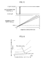
- FIG. 2 is a graph showing temperature characteristics of the storage capacity of a selective reduction catalyst.
- the temperature characteristics of the new article are shown by the dot-dashed line, and the temperature characteristics of the degraded article are shown by the solid line.
- the storage capacity of the selective reduction catalyst has a characteristic of declining with rising catalyst temperature as shown in FIG. 2 , and furthermore, this temperature characteristic changes so as to decline in response to the advancement of degradation of the catalyst.
- FIG. 3 is a graph showing the output characteristic of the ammonia sensor.
- Such ammonia sensors output a detection signal NH3 CONS of a level substantially proportional to the ammonia concentration of exhaust, as shown in FIG. 3 .
- FIG. 4 is a block diagram showing a module configuration executing urea injection control of the present embodiment. This function is realized by the ECU 3 equipped with the above such hardware configuration.
- a reference injection amount G UREA_BS to be the reference relative to overall injection amount is calculated by the reference injection amount calculating portion 31 described later, the reference injection amount G UREA _ BS is corrected by adding by way of an adder 33 the switching injection amount G UREA_SW calculated by the switching injection amount calculating portion 32 described later, and the corrected reference injection amount determined as the urea injection amount G UREA (refer to the follow formula (1)).
- G UREA k G UREA_BS k + G UREA_SW k
- the notation (k) is a notation expressing computing time set synchronously with a urea injection cycle (e.g., 0.25 to 3.00 seconds).
- a urea injection cycle e.g. 0.25 to 3.00 seconds.
- G UREA (k) being a urea injection amount in a current control timing
- G UREA (k-1) indicates being a urea injection amount in a control timing one cycle previous (previous time).
- the notation (k) is omitted as appropriate in the following explanation.
- the state of the selective reduction catalyst 23 is estimated by a state estimation unit 35 and a storage capacity correction unit 36 when calculating the reference injection amount G UREA_BS and the switching injection amount G UREA_SW by this reference injection amount calculating portion 31 and switching injection amount calculating portion 32. More specifically, the state estimation unit 35 and the storage capacity correction unit 36 respectively calculate the estimated values ST UREA and ST UREA_MAX of the storage amount and storage capacity of the selective reduction catalyst 23, and perform output thereof to the switching injection amount calculating portion 32.
- degradation of the selective reduction catalyst 23 is determined by the catalyst degradation determination unit 37 based on the outputs of the state estimation unit 35 and the storage capacity correction unit 36.
- FIG. 5 is a graph showing behavior of the slip determination portion 34.
- the slip determination portion 34 determines the existence of ammonia downstream of the selective reduction catalyst, i.e. the occurrence of ammonia slip of the selective reduction catalyst, based on the output value NH3 CONS of the ammonia sensor, and determines a slip determination flag F NH3_SLIP indicating being a state in which ammonia slip has occurred. More specifically, as shown in FIG. 5 , a threshold value NH3 JD for the output value NH3 CONS of the ammonia sensor is set to near a value 0.
- the error in the output value NH3 CONS of the ammonia sensor becomes larger depending on the absolute value of the output value NH3 CONS , along with gain variation of the ammonia sensor.
- this slip determination portion 34 it is possible to stably determine the occurrence of ammonia slip with high precision, irrespective of the gain variation of the ammonia sensor, by setting the threshold value NH3 JD for the output value NH3 CONS to near the value 0 at which the error is small.
- the reference injection amount G UREA_BS is calculated in order to inject urea water of an amount appropriate for the NOx amount discharged from the engine. More specifically, the reference injection amount calculating portion 31 calculates the reference injection amount G UREA_BS by searching a predetermined control map, for example, based on a parameter correlating to an operating state of the engine, such as the engine revolution speed NE or a load parameter TRQ of the engine (refer to the following formula (3)).
- G UREA_BS k ⁇ calculated by searching the map shown in FIG .6 , based on the engine load TRQ k and the engine revolution speed NE k
- FIG. 6 is a graph showing an example of a control map for determining the reference injection amount G UREA_BS .
- the reference injection amount G UREA_BS is determined to be a larger value with the revolution speed NE of the engine or the load parameter TRQ increasing.
- the NOx emission amount increases by the combustion temperature of the air/fuel mixture rising with the load parameter TRQ of the engine increasing, and the NOx emission amount per unit time increases with the revolution speed NE of the engine rising.
- the fuel injection amount or the amount of new air in the cylinder may be used as the load parameter of the engine.
- the reference injection amount G UREA_BS may be calculated based on the output value NOX CONS of this NOx sensor as the parameter correlating to the operating state of the engine.
- the switching injection amount calculating portion 32 calculates the switching injection amount G UREA _ SW based on the slip determination flag F NH3_SLIP , as well as the estimated value ST UREA of the storage amount and the estimated value ST UREA_MAX of the storage capacity calculated by the state estimation unit 35 and the storage capacity correction unit 36 described later.
- a switch storage amount ST UREA_SW described later is set to a value that is somewhat smaller than the estimated value ST UREA_MAX of the storage capacity (refer to formulas (4) and (5) described later). Then, the switching injection amount G UREA _ SW is calculated so that the estimated value ST UREA of the storage amount falls between this estimated value ST UREA_MAX of the storage capacity and the switch storage amount ST UREA_SW (refer to formulas (6), (7) and (8) described later).
- FIG. 7 is a graph schematically showing a relationship between the estimated value ST UREA_MAX of the storage capacity and the catalyst temperature (output value T SCR of the catalyst temperature sensor).
- the estimated value ST UREA_MAX of the storage capacity of the selective reduction catalyst decreases with the catalyst temperature rising.
- the switch storage amount ST UREA_SW is set to a value that is somewhat smaller than the estimated value ST UREA_MAX , as shown by the dotted line in FIG. 7 .
- a temperature coefficient KSTSW is found by searching a control map such as that shown in FIG. 8 , based on the output value T SCR of the catalyst temperature sensor (refer to the following formula (4)). As shown in FIG. 8 , this temperature coefficient KSTSW is preferably determined between 0 and 1 so as to become larger in a temperature range in which the storage capacity is large, and then to become smaller in a temperature range in which the storage capacity is small. KSTSW k ⁇ calculated by searching the map shown in FIG .8 , based on the output value T SCR ⁇ of the catalyst temperature
- the product of multiplying the above-mentioned temperature coefficient KSTSW by the estimated value ST UREA_MAX of the storage capacity is set as the switch storage amount ST UREA_SW .
- ST UREA_SW k KSTSW k ST UREA_MAX k
- the difference between the estimated value ST UREA_MAX of the storage capacity and the switch storage amount ST UREA_SW is set so as to become smaller with the catalyst temperature rising, as shown by the dotted line in FIG. 7 .
- the above-mentioned temperature coefficient KSTSW may be made constant, irrespective of the output value T SCR of the temperature sensor.
- the switch storage amount ST UREA_SW may be set by subtracting a predetermined value from the estimated value ST UREA-MAX of the storage capacity.
- an injection amount switching flag F UREA_SW is determined based on the estimated value ST UREA of the storage amount, the switch storage amount ST UREA_SW , and the slip determination flag F NH3_SLIP , as shown in the following formula (6).
- the injection amount switching flag F UREA_SW is set to “1” from “0” in response to ammonia slip occurring in the selective reduction catalyst, and the slip determination flag F NH3_SLIP having become “1” from “0” .
- the injection amount switching flag F UREA_SW is reset to "0" from “1” in response to the estimated value ST UREA of the storage capacity having fallen below the above-mentioned switch storage amount ST UREA_SW .
- the switching injection amount G UREA_SW is calculated as shown in the following formula (7), according to the injection amount switching flag F UREA_SW determined in the above way.
- the injection amount switching flag F UREA_SW being "1"
- the injection amount of urea water is determined to be a slightly excessive state
- the product of multiplying the exhaust density DEN Ex and the estimated value V EX of the exhaust volume by a negative predetermined supply-excess time correction value G UREA_SW_UND is determined as the switching injection amount G UREA_SW .
- the injection amount switching flag F UREA_SW being "0"
- the injection amount of urea water is determined to be a slightly insufficient state, and the product of multiplying the exhaust density DEN EX and the estimated value V EX of the exhaust volume by a positive predetermined supply-deficient time correction value G UREA_SW_OVD is determined as the switching injection amount G UREA_SW .
- the reference injection amount G UREA_BS is reduced in amount in response to ammonia slip having been determined to have occurred, after which it is increased in amount in response to the estimated value ST UREA of the storage capacity having fallen below the switch storage amount ST UREA_SW .
- the estimated value V EX of the exhaust volume is calculated by searching a predetermined control map, for example, based on the engine revolution speed NE or the load parameter TRQ (refer to the following formula (8)).
- a predetermined control map for example, based on the engine revolution speed NE or the load parameter TRQ (refer to the following formula (8)).
- the map shown in FIG. 9 is used, for example.
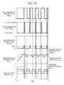
- FIG. 10 presents time charts showing behavior of the injection amount switching flag F UREA_SW , slip determination flag F NH3_SLIP , ammonia sensor output value NH3 CONS , storage amount estimated value ST UREA , storage capacity estimated value ST UREA_MAX , and urea injection amount G UREA .
- FIG. 10 a case is shown in which the engine operating state is made constant, and the amount of NOx discharged from the engine is made constant.
- Operation is started from a state in which ammonia is not being stored in the selective reduction catalyst.
- the slip determination flag F NH3_SLIP and the injection amount switching flag F UREA_SW are "0", and thus the switching injection amount G UREA_SW is set to a positive value.
- the urea injection amount G UREA becomes an amount correcting the reference injection amount G UREA_BS to the increased amount side.
- the estimated value ST UREA of the storage amount increases, and when it reaches the estimated value ST UREA_MAX of the storage capacity, the output value NH3 CONS of the ammonia sensor begins to increase.
- Ammonia slip is determined to have occurred and the slip determination flag F NH3_SLIP is set to "1" in response to the output value NH3 CONS of the ammonia sensor having exceeded the threshold value NH3 JD .
- the injection amount switching flag F UREA_SW is set to "1" while the switching injection amount G UREA_SW is simultaneously set to a negative value. With this, the urea injection amount G UREA becomes an amount correcting the reference injection amount G UREA_BS to the reduced amount side.
- the ammonia sensor output value NH3 CONS begins to decrease.
- the slip determination flag F NH3_SLIP is reset to "0".
- the injection amount switching flag F UREA_SW is reset to "0" and the switching injection amount G UREA_SW is set again to a positive value.
- the urea injection amount G UREA becomes an amount correcting the reference injection amount G UREA_BS to the increased amount side.
- the urea injection amount G UREA is alternately corrected to the increased amount side and reduced amount side relative to the reference injection amount G UREA_BS , so that the storage amount estimated value ST UREA oscillates between the storage capacity estimated value ST UREA_MAX and the switch storage amount ST UREA_SW .
- the estimated value ST UREA of the storage amount and the estimated value ST UREA_MAX indicating the state of the selective reduction catalyst are calculated, and a slip estimation flag F NH3_SLIP_HAT for determining the occurrence of ammonia slip is determined based on these estimated values ST UREA and ST UREA_MAX .
- the estimated value ST UREA_MAX of the storage capacity is calculated in the following sequence.
- a reference value ST UREA_MAX_BS of the storage capacity is calculated by searching a predetermined control map, for example, based on the output value T SCR of the catalyst temperature sensor (refer to the following formula (9)).
- ST UREA_MAX_BS k ⁇ calculated by searching the map shown in FIG .11 , based on the output value T SCR of catalyst temperature sensor
- FIG. 11 is a graph showing an example of a control map for determining the reference value ST UREA_MAX_BS of the storage capacity. As shown in FIG. 11 , with this control map, the reference value ST UREA_MAX _ BS of the storage capacity is set so as to become smaller with the catalyst temperature rising, in accordance with the characteristics of the selective reduction catalyst.
- the product of multiplying a storage capacity correction value KVNS by the reference value ST UREA_MAX_BS thus calculated is set as the estimated value ST UREA_MAX of the storage capacity, as shown in the following formula (10).
- the storage capacity correction value KVNS corrects the reference value ST UREA_MAX_BS by multiplying by this, is a value for causing the estimated value ST UREA_MAX of the storage capacity to adaptively change, and is calculated by the storage capacity correction unit 36 described later.
- the notation (n) indicates the computing time of the storage capacity correction unit 36 described later.
- ST UREA_MAX k KVNS n ST UREA_MAX_BS k
- the storage capacity correction value KVNS was multiplied by the reference value ST UREA_MAX_BS in the present embodiment, it is not limited thereto, and may be added.
- the estimated value ST UREA of the storage amount is calculated in the following sequence.
- a temporary value ST UREA_TEMP (k) of the storage amount estimated value is calculated by adding a current stored portion (G UREA (k) - G UREA BS (k)) to a previous value ST UREA (k-1) of the storage amount estimated value, and as shown in the following formula (12), the estimated value ST UREA (k) of the storage amount can be determined by conducting limit processing of the upper limit value and the lower limit value on this temporary value ST UREA_TEMP (k).
- the slip estimation flag F NH3 SLIP HAT estimating the occurrence of ammonia slip is set in the following sequence.
- the slip estimation flag F NH3 SLIP HAT can be determined by comparing the sizes of the storage amount estimated value ST UREA and the storage capacity estimated value ST UREA MAX , as shown in the following formula (13).
- F NH ⁇ 3 _SLIP_HAT k ⁇ 1 : ST UREA k ⁇ ST UREA_MAX k 0 : ST UREA k ⁇ ST UREA_MAX k
- the estimated slip amount G UREA SLIP is calculated based on a difference between the temporary value ST UREA TEMP of the storage amount estimated value and the storage capacity ST UREA MAX , as shown in the following formula (14).
- G UREA_SLIP k ⁇ ST UREA_TEMP k - ST UREA_MAX k : ST UREA_TEMP k - ST UREA_MAX k > 0 0 : ST UREA k - ST UREA_MAX k ⁇ 0
- a predetermined switch coefficient K UREA_NH3_GAS is multiplied by the estimated slip amount G UREA SLIP with a scale of the urea water amount (g), the occupied volume of ammonia generated from the urea water amount is calculated, then this is further divided by the estimated value V EX of the exhaust volume to calculate the slip determination value NH3 SLIP HAT , as shown in the following formula (15).
- NH ⁇ 3 SLIP_HAT k G UREA_SLIP k K UREA_NH ⁇ 3 _GAS / V EX k
- the slip estimation flag F NH3 SLIP HAT can be determined by comparing this slip determination value NH3 SLIP HAT with the size of the predetermined threshold value NH3 SLIP JD , as shown in the following formula (16).
- F NH ⁇ 3 _SLIP_HAT k ⁇ 1 : NH ⁇ 3 SLIP_HAT k ⁇ NH ⁇ 3 SLIP_JD 0 : NH ⁇ 3 SLIP_HAT k ⁇ NH ⁇ 3 SLIP_JD
- the storage capacity correction value KVNS for correcting the estimated value ST UREA MAX of the storage capacity is calculated based on a difference between the occurrence time of ammonia slip determined by the slip determination portion 34 (computing time for which the slip determination flag F NH3 SLIP was set to “1" from “0") and the occurrence time of ammonia slip estimated by the state estimation unit 35 (computing time for which the slip estimation flag F NH3 SLIP HAT was set to "1" from “0").
- FIG. 12 is a block diagram showing a configuration of the storage capacity correction unit 36.
- the temperature characteristic of the storage capacity changes so as to decline in accordance with the advancement of degradation of the catalyst.
- the decline in the storage capacity due to this advancement in degradation is not a uniform decline in all of the temperature regions, but rather shows variation that differs in each temperature region.
- an update amount D KVNS to the storage capacity correction value KVNS is calculated based on the slip determination flag F NH3 SLIP and the slip estimation flag F NH3 SLIP HAT .
- the local correction value (KVNS i ) of each region is updated based on the above-mentioned update amount D KVNS and the weighting function (W i ) of each region calculated in a weighting function setting portion 362.
- KVNS i the sum total of products of the above-mentioned local correction values (KVNS i ) of each region updated and the values of the weighting functions of each region according to the catalyst temperature is calculated, and this is set as the storage capacity correction value KVNS.
- the update amount calculating portion 361 calculates the update amount D KVNS to the storage capacity correction value KVNS, based on a time for which the slip determination flag F NH3 SLIP was set to "1" from “0” (time for which it was determined that ammonia slip occurred) and a time for which the slip estimation flag F NH3 SLIP HAT was set to "1" from “0” (time for which it was estimated that ammonia slip occurred). Two variations are considered for specific sequences of calculating this update amount D KVNS . Hereinafter, sequences of the two variations of TYPE 1 and TYPE 2 will each be explained.
- the update amount D DVNS is set to a positive predetermined value D KVNS MOD in order to correct the slip capacity estimated value ST UREA MAX to the increased amount side.
- the update amount D KVNS is set to a negative predetermined value (- D KVNS_MOD ) in order to correct the storage capacity estimated value ST UREA MAX to the reduced amount side.
- the computing time of the storage capacity correction unit 36 indicated by the notation (n) is preferably synchronous with the urea injection cycle indicated by the notation (k).
- the update amount D KVNS is set to a predetermined amount that is not "0" while there is a difference between the time for which the slip determination flag F NH3 SLIP is set to "1" and the time for which the slip estimation flag F NH3 SLIP HAT is set to "1" in TYPE 2 as well.
- the update amount D KVNS is set to a value that is not "0" only in a case in which a flag F VNS_CAL is set to "1".
- the flag F VNS CAL defining this computing timing is set based on the following formula (19). In other words, the flag F VNS CAL is set to "1" from “0” when the slip determination flag FNH3 SLIP is set to “1” from “0", or when the slip estimation flag F NH3 SLIP HAT is set to “1” from “0". Thereafter, the flag F VNS CAL is also reset to "0" in response to the slip determination flag F NH3_SLIP being reset to "0".
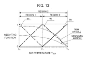
- the domains are divided into region 1 (T 0 , T 1 ), region 2 (T 0 , T 2 ), and region 3 (T 1 , T 2 ).
- T 0 ⁇ T 1 ⁇ T 2 is defined. Therefore, region 1 and region 2 overlap in the interval (T 0 , T 1 ), and region 2 and region 3 overlap in the interval (T 1 , T 2 ).
- the weighting function W 1 is set so as to have a value that is not 0 in region 1 (T 0 , T 1 ). More specifically, the weighting function W 1 is set so as to decrease from 1 to 0 in the interval (T 0 , T 1 ).
- the weighting function W 2 is set so as to have a value that is not 0 in region 2 (T 0 , T 2 ). More specifically, the weighting function W 2 is set so as to rise from 0 to 1 in the interval (T 0 , T 1 ) and is set so as to decrease from 1 to 0 in the interval (T 1 , T 2 ). Therefore, the weighting function W 1 and the weighting function W 2 intersect in the middle of the interval (T 0 , T 1 ).
- the weighting function W 3 is set so as to have a value that is not 0 in region 3 (T 1 , T 2 ). More specifically, the weighting function W 3 is set so as to rise from 0 to 1 in the interval (T 1 , T 2 ). Therefore, the weighting function W 2 and the weighting function W 3 intersect in the middle of the interval (T 1 , T 2 ).
- the number regions defining and the number of weighting functions is not limited to 3, and may be 4 or more.
- the estimated value of the exhaust volume may be added as a domain defining the weighting functions.
- a value is output by the weighting function setting portion 362 according to the catalyst temperature sensor output value T SCR .
- the products of multiplying the update amount D KVNS calculated by the update amount calculating portion 361 by each weighting function value output from the weighting function setting portion 362 are output to the local correction value calculating portion 364.
- the forgetting factor LAMBDA i is set to a setting value LAMBDA FGT _ H (e.g., 0.995) for excess time at an excess time at which the local correction value KVNS i is larger than the threshold value KVS FGT H (e.g., 1.2).
- the forgetting factor LAMBDA i is set to a setting value LAMBDA FGT _ L (e.g., 0.990) for deficient time at a deficient time at which the local correction value KVNS i is smaller than the threshold value KVS FGT L (e.g., 0.1).
- the forgetting factor LAMBDA i is set to "1".
- the threshold value KVS FGT L is set to be smaller than a degradation determination threshold value KVNS AGED described later, which is set in order to determine degradation of the selective reduction catalyst.
- LAMBDA i n ⁇ LAMBDA FGT_H : KVNS i ⁇ n - 1 ⁇ KVS FGT_H 1 : KVS FGT_L ⁇ KVNS i ⁇ n - 1 ⁇ KVS FGT_H LAMBDA FGT_L : KVNS i ⁇ n - 1 ⁇ KVS FGT_L
- the local correction value KVNS i is updated based on the forgetting factor LAMBDA i (n) thus calculated, the previous value KVNS i (n-1) of the local correction value, the weighting function value W i (n), and the update amount D KVNS (n).
- the sum total of the products of the local correction values KVNS i (n) and the weighting function values W i (n) is calculated as shown in the following formula (23), and this is set as the storage capacity correction value KVNS(n).
- degradation of the selective reduction catalyst is determined by determining the degradation determination flag F SCR AGD , based on at least any of the parameters correlating to the degradation progression extent of the selective reduction catalyst such as the estimated value ST UREA of the storage capacity, local correction value KVNS i , and storage capacity correction value KVNS. It should be noted that three variations are considered for the specific sequence of determining the degradation of the catalyst. Hereinafter, sequences of the three variations of TYPE 1, TYPE 2 and TYPE 3 will each be explained.
- the degradation determination threshold value KVNS AGED for determining degradation of the selective reduction catalyst is set for the storage capacity correction value KVNS. Then, in a case of the storage capacity correction value KVNS becoming smaller than the degradation determination threshold value KVNS AGED , it is determined that the selective reduction catalyst has degraded, and the degradation determination flag F SCR AGD is set to "1" from "0".
- F SCR_AGD k ⁇ 0 : normal KVNS n ⁇ KVNS AGED 1 : degraded KVNS n ⁇ KVNS AGED
- the degradation determination threshold value KVNS AGED is set for a second component KVNS 2 , which is defined throughout the entire temperature region, among the local correction value KVNS i . Then, in a case of the second component KVNS 2 of the local correction value becoming smaller than the degradation determination threshold value KVNS AGED , it is determined that the selective reduction catalyst has degraded, and the degradation determination flag F SCR AGD is set to "1" from "0".
- F SCR_AGD k ⁇ 0 : normal KVNS 2 n ⁇ KVNS AGED 1 : degraded KVNS 2 n ⁇ KVNS AGED
- the degradation determination threshold value ST UREA AGED for determining degradation of the selective reduction catalyst is set for the estimated value ST UREA MAX of the storage capacity. Then, in a case of the storage capacity estimated value ST UREA_MAX become smaller than the degradation determination threshold value ST UREA AGED , it is determined that the selective reduction catalyst has degraded, and the degradation determination flag F SCR AGD is set to "1" from "0".
- F SCR_AGD k ⁇ 0 : normal ST UREA_MAX k ⁇ ST UREA_AGED 1 : degraded ST UREA_MAX k ⁇ ST UREA_AGED
- FIG. 14 is a flowchart showing a sequence of urea injection control executed by an ECU.
- Step S1 it is distinguished whether a urea fault flag F UREANG is "1".
- This urea fault flag F UREANG is set to "1" when it is determined that the urea injection device has failed in determination processing, which is not illustrated, and is set to "0" at times except for this.
- Step S8 is advanced to, and after the urea injection amount G UREA has been set to "0", this processing ends.
- Step S2 is advanced to.
- Step S2 it is distinguished whether the urea remaining amount Q UREA is less than a predetermined value Q REF .
- This urea remaining amount Q UREA indicates a remaining amount of urea water in the urea tank, and is calculated based on an output of the urea level sensor.
- Step S3 is advanced to, and in a case of being NO, Step S4 is advanced to.
- Step S3 the urea remaining amount warning light is illuminated, and Step S8 is advanced to, and after the urea injection amount G UREA has been set to "0", this processing ends.
- Step S4 it is distinguished whether a catalyst warm-up timer value T MAST is larger than a predetermined value T MLMT .
- This catalyst warm-up timer value T MAST is a value keeping the warm-up time of the selective reduction catalyst after engine startup.
- Step S5 is advanced to.
- Step S8 is advanced to, and after the urea injection amount G UREA has been set to "0", this processing ends.
- Step S5 it is distinguished whether a sensor fault flag F SENNG is "0".
- This sensor fault flag F SENNG is set to "1" when it is determined that the ammonia sensor or the catalyst temperature sensor has failed in the determination processing, which is not illustrated, and is set to "0" at times except for this.
- Step S6 is advanced to.
- Step S8 is advanced to, and after the urea injection amount G UREA has been set to "0", this processing ends.
- Step S6 it is distinguished whether an ammonia sensor activity flag F NH3ACT is 1.
- This ammonia sensor activity flag F NH3ACT is set to "1" when it is determined that the ammonia sensor has reached an active state in determination processing, which is not illustrated, and is set to "0" at times except for this.
- Step S7 is advanced to.
- Step S8 is advanced to, and after the urea injection amount G UREA has been set to "0", this processing ends.
- Step S7 it is distinguished whether the catalyst temperature sensor output value T SCR is larger than a predetermined value T SCR ACT . In a case of this determination being YES, it is determined that the selective reduction catalyst has been activated, and Step S9 is advanced to. In a case of this determination being NO, it is determined that the selective reduction catalyst has not been activated yet and that urea injection should be stopped, Step S8 is advanced to, and after the urea injection amount G UREA has been set to "0", this processing ends.
- Step S9 the slip estimation flag F NH3_SLIP_HAT and the storage capacity estimated value KVNS are calculated by the aforementioned state estimation unit and storage capacity correction unit based on formulas (13) to (23).
- Step S10 the urea injection amount G UREA is calculated by the slip determination portion, state estimation unit, reference injection amount calculating portion, and switching injection amount calculating portion based on formulas (1) to (12), and Step S11 is advanced to.
- Step S11 it is distinguished whether the catalyst temperature sensor output value T SCR is within a range of the upper limit value T SCR H and the lower limit value T SCR L .
- this determination being YES, it is determined to be a state suited for determining degradation of the selective reduction catalyst, and Step S12 is advanced to. In a case of this determination being NO, this processing ends immediately.
- the upper limit value T SCR H is set to 300°C and the lower limit value T SCR L is set to 230°C, for example.
- Step S12 the degradation determination flag F SCR AGD is updated by the catalyst degradation determination unit based on any of formulas (24), (25) and (26), and Step S13 is advanced to.
- Step S13 it is distinguished whether the degradation determination flag T SCR AGD is "1". In a case of this determination being YES, Step S14 is advanced to, and after the catalyst degradation warning light has been illuminated, this processing ends. In a case of this determination being NO, this processing ends immediately.
- CASE 1 is a case in which a selective reduction catalyst that is a new article is used and there is no gain variation in the ammonia sensor
- CASE 2 is a case in which the selective reduction catalyst that is a new article is used and there is gain variation in the ammonia sensor
- CASE 3 is a case in which a degraded selective reduction catalyst is used and there is no gain variation in the ammonia sensor
- CASE 4 is a case in which a degraded selective reduction catalyst is used and there is gain variation in the ammonia sensor.
- FIG. 15 shows the simulation results of CASE 1. It should be noted that, in the graph of the NOx amount in FIG. 15 , the variation in the NOx amount discharged to outside the system indicated by the dotted line is substantially the same as the variation in the NOx amount discharged to downstream of the selective reduction catalyst indicated by the thin solid line. In addition, in the graph of the ammonia amount, the ammonia amount discharged to outside the system indicated by the thin solid line is substantially constant at "0". Moreover, in the graph of the storage amount, the estimated value of the storage capacity indicated by the thick solid line shows variation substantially the same as the actual storage capacity indicated by the dashed line, and the storage amount indicated by the thin solid line shows variation substantially that same as the actual storage amount indicated by the dotted line.
- CASE 1 is considered to be a state in which the error of the control system is the smallest, since the selective reduction catalyst is a new article and there is also no gain variation of the ammonia sensor. Therefore, although ammonia slip by the selective reduction catalyst occurs with the operating state of the engine becoming high load, ammonia discharged to outside the system amounts to nothing. In addition, since the actual storage amount is controlled to near the actual storage capacity apart for the duration in which the storage capacity is temporarily increased from low load operation being performed intermittently, the NOx purification rate of the selective reduction catalyst is also maintained to be high.
- the storage capacity correction value KVNS is maintained at "1", a result of which the error in the estimated value ST UREA MAX of the storage capacity relative to the actual storage capacity is also small. This fact is consistent with using a selective reduction catalyst that is a new article.
- FIG. 16 shows the simulation results of CASE 2. It should be noted that, in the graph of the NOx amount in. FIG. 16 , the variation in the NOx amount discharged to outside the system indicated by the dotted line is substantially the same as the variation in the NOx amount discharged to downstream of the selective reduction catalyst indicated by the thin solid line. In addition, in the graph of the ammonia amount, the ammonia amount discharged to outside the system indicated by the thin solid line is substantially constant at "0". Moreover, in the graph of the storage amount, the estimated value of the storage capacity indicated by the thick solid line shows variation substantially the same as the actual storage capacity indicated by the dashed line, and the storage amount indicated by the thin solid line shows variation substantially that same as the actual storage amount indicated by the dotted line.
- CASE 2 is a case of a state in which gain variation in the ammonia sensor occurs, the effect thereof is small due to using the output value of the ammonia sensor as binary information. Therefore, the simulation results of CASE 2 are substantially the same as the simulation results of CASE 1. Therefore, it has been verified that, according to the present embodiment, even in a case of gain variation in the ammonia sensor having occurred, it is possible to prevent ammonia from discharging to outside the system, while stably maintaining the NOx purification rate to be high.
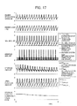
- FIG. 17 shows the simulation results of CASE 3. It should be noted that, in the graph of the NOx amount in FIG. 17 , the variation in the NOx amount discharged to outside the system indicated by the dotted line is substantially the same as the variation in the NOx amount discharged to downstream of the selective reduction catalyst indicated by the thin solid line. In addition, in the graph of the ammonia amount, the ammonia amount discharged to outside the system indicated by the thin solid line is substantially constant at "0".
- CASE 3 is a state in which the selective reduction catalyst has degraded, immediately after operation start, the estimated value ST UREA MAX of the storage capacity and the estimated value ST UREA of the storage amount deviate greatly from the actual storage capacity and the actual storage amount.
- the storage capacity correction value KVNS will gradually decrease from "1", and can be brought to the actual value along with the estimated value ST UREA MAX of the storage capacity and the estimated value ST UREA of the storage amount by adaptively correcting to a degraded state. Therefore, it has been verified that, according to the present embodiment, even in a state in which the selective reduction catalyst has degraded, it is possible to prevent ammonia from being discharged to outside the system, while stably maintaining the NOx purification rate to be high.
- FIG. 18 shows the simulation results of CASE 4. It should be noted that, in the graph of the NOx amount in FIG. 18 , the variation in the NOx amount discharged to outside the system indicated by the dotted line is substantially the same as the variation in the NOx amount discharged to downstream of the selective reduction catalyst indicated by the thin solid line. In addition, in the graph of the ammonia amount, the ammonia amount discharged to outside the system indicated by the thin solid line is substantially constant at "0".
- CASE 4 is a state in which gain variation in the ammonia sensor occurs and the selective reduction catalyst has degraded, and is considered to be the state in which the error of the control system is the largest.
- the simulation results of CASE 4 are substantially the same as the simulation results of CASE 3. Therefore, it has been verified that, according to the present embodiment, it has robustness against gain variation of the ammonia sensor and degradation of the selective reduction catalyst.
- the slip determination portion determines the existence of the occurrence of ammonia slip based on the output value NH3 CONS of the ammonia sensor.
- the determination result of such an existence of ammonia is considered to not be greatly influenced by the gain variation of the ammonia sensor. Therefore, it is possible to determine the urea injection amount G UREA without being affected by the gain variation of the ammonia sensor.
- the estimated value ST UREA of the storage amount and the estimated value ST UREA MAX of the storage capacity of the selective reduction catalyst were set as values having a scale of the amount of urea water in the above-mentioned embodiment, it is not limited thereto. For example, similar effects are exerted even if set to values having a scale of the amount of ammonia generated from this urea water.
- ammonia may be directly supplied without supplying urea water to generate ammonia from this urea water.
- the additive to be the source of ammonia is not limited to urea water, and another additive may be used.
- the reducing agent for reducing NOx is not limited to ammonia.
- the present invention can be applied to an exhaust purification system using hydrocarbons in place of ammonia, for example, as the reducing agent for reducing NOx.
- An exhaust purification system is provided that can continuously maintain a NOx purification rate to be high while suppressing the occurrence of ammonia slip.
- the exhaust purification system includes a slip determination portion 34 that determines the occurrence of ammonia slip based on an output value NH3 CONS of an ammonia sensor 26.
- a reference injection amount calculating portion 31 calculates a reference injection amount G UREA BS based on a parameter correlating to an operating state of an engine.
- a switching injection amount calculating portion 32 decreases in amount a urea injection amount G UREA by setting a switching injection amount G UREA SW to a negative value in response to having determined that ammonia slip has occurred, and increases in amount the injection amount G UREA by setting the switching injection amount G UREA SW to a positive value in response to a storage amount estimated value ST UREA having fallen below a predetermined switch storage amount ST UREA SW .
Landscapes
- Chemical & Material Sciences (AREA)
- Engineering & Computer Science (AREA)
- Chemical Kinetics & Catalysis (AREA)
- Health & Medical Sciences (AREA)
- Toxicology (AREA)
- Combustion & Propulsion (AREA)
- Mechanical Engineering (AREA)
- General Engineering & Computer Science (AREA)
- Exhaust Gas After Treatment (AREA)
- Exhaust Gas Treatment By Means Of Catalyst (AREA)
Abstract
Description
- This application is based on and claims the benefit of priority from Japanese Patent Application No.
2009-252028, filed on 2 November 2009 - The present invention relates to an exhaust purification system for an internal combustion engine, and particularly relates to an exhaust purification system for an internal combustion engine equipped with a selective reduction catalyst that reduces NOx in the exhaust under the presence of a reducing agent.
- Conventionally, as one exhaust purification system that purifies NOx in exhaust, a system has been proposed in which a selective reduction catalyst that selectively reduces NOx in the exhaust by way of a reducing agent is provided in an exhaust channel. For example, with an exhaust purification system of urea addition type, urea water is supplied from an upstream side of the selective reduction catalyst, ammonia is generated by thermal decomposition or hydrolysis of this urea water by the heat of the exhaust, and the NOx in the exhaust is selectively reduced by this ammonia. In addition to such a system of urea addition type, for example, a system has also been proposed that generates ammonia by heating a compound of ammonia such as ammonia carbide, and directly adds this ammonia. A system of urea addition type will be explained hereinafter.
- With such a selective reduction catalyst, in a case of the injection amount of urea water being less than an optimum amount, the NOx purification rate declines from the ammonia being consumed in the reduction of NOx being insufficient, and in a case of being larger than this optimum amount, the ammonia that has become surplus in the reduction of NOx is discharged. As a result, appropriately controlling the injection amount of urea water has been important in exhaust purification systems provided with a selective reduction catalyst. Therefore, in
Patent Document 1 andPatent Document 2, systems are exemplified that estimate a NOx purification rate of the selective reduction catalyst, and control an injection amount of urea water based on this estimation. - With the exhaust purification system disclosed in Japanese Unexamined Patent Application Publication No.
2004-100700 - In addition, with the exhaust purification system disclosed in Japanese Unexamined Patent Application Publication No.
2006-274986 - However, the NOx reduction rate of the selective reduction catalyst changes not only by the above such composition of the exhaust and temperature of the selective reduction catalyst, but also according to the degradation state of the selective reduction catalyst. In addition, there is variability in purification performance between individual units. Therefore, it is difficult to always optimally control the injection amount of urea water with exhaust purification systems such as those exemplified in
Patent Documents - Consequently, a technique is considered below that more directly detects the NOx purification rate of the selective reduction catalyst, and controls the injection amount of urea water based on this.
-
FIG. 19 is a schematic diagram showing a configuration of a conventionalexhaust purification system 80. - As shown in
FIG. 19 , anoxidation catalyst 83, aurea injection valve 85 that injects urea water as a reducing agent that is stored in aurea tank 84 into anexhaust channel 82, and aselective reduction catalyst 86 that reduces NOx in the exhaust under the presence of ammonia are provided in sequence from an upstream side to a downstream side in theexhaust channel 82 of anengine 81. In addition, atemperature sensor 87 that detects a temperature of theselective reduction catalyst 86 and a NOx sensor 88 that detects a NOx amount on a downstream side of theselective reduction catalyst 86 are provided as sensors for observing the purification performance of the selective reduction catalyst. - With this
exhaust purification system 80, for example, the NOx amount of exhaust discharged from theengine 81 is estimated by way of a map set in advance, and the injection amount of urea water from theurea injection valve 85 is determined based on this NOx amount and the catalyst temperature detected by thetemperature sensor 87. In particular, herein, the degradation state of theselective reduction catalyst 86 can be estimated based on a difference between an output value of the NOx sensor 88 and the NOx amount of exhaust thus estimated. With this exhaust purification system, the injection amount of urea water is corrected in accordance with the degradation state of theselective reduction catalyst 86 estimated in the above way. -
FIG. 20 shows relationships between the NOx amount and ammonia amount in the exhaust downstream of the selective reduction catalyst and the output value of the NOx sensor for the aforementioned conventional exhaust purification system. More specifically,FIG. 20 shows, in sequence from the upper graph, relationships between the NOx amount of exhaust downstream of the selective reduction catalyst, the ammonia amount of exhaust downstream of the selective reduction catalyst, and the output value of the NOx sensor, with the urea water injection amount. - When the injection amount of urea water increases, the NOx purification rate of the selective reduction catalyst rises due to the ammonia generated in the selective reduction catalyst also increasing. As a result, the NOx amount downstream of the selective reduction catalyst decreases accompanying the injection amount of urea water increasing, as shown in
FIG. 20 . In addition, when exceeding the urea water injection amount shown by the star, the NOx amount is substantially constant irrespective of the urea water injection amount. In other words, urea water of the amount exceeding the star indicates being surplus relative to that reducing the NOx generated. - In addition, herein, the ammonia generated from the urea water that is surplus is not consumed in the reduction of NOx, and is either stored in the selective reduction catalyst or discharged to downstream of the selective reduction catalyst. Therefore, as shown in
FIG. 20 , the ammonia amount of exhaust downstream of the selective reduction catalyst increases, when exceeding the injection amount of urea water indicated by the star. It should be noted that reducing agent discharging from the selective reduction catalyst to the downstream side thereof in this way is referred to hereinafter as "reducing agent slip", and in a case of using ammonia as the reducing agent in particular, is referred to as "ammonia slip". - Since the urea water injection amount indicated by the star in
FIG. 20 can both minimize the NOx amount and ammonia amount in the above way, it is the optimum injection amount for this exhaust purification system. - However, as shown in
FIG. 20 , the output value of the NOx sensor shows a downward convex characteristic in which the output value of this optimum injection amount is a minimum point. This is because existing NOx sensors in the detection principles thereof are sensitive not only to NOx, but also to ammonia. Therefore, it is impossible to determine whether the injection amount of urea water is insufficient relative to the optimum injection amount or excessive, with only the output value from the NOx sensor. - Incidentally, in addition to the ability to reduce NOx under the presence of ammonia in the above way, the selective reduction catalyst has the ability to store ammonia.
-
FIG. 21 is a graph showing a relationship between a storage rate and NOx purification rate of the selective reduction catalyst. Herein, the storage rate refers to a proportion of the ammonia amount stored in the selective reduction catalyst relative to the maximum value thereof. - As shown in
FIG. 21 , the NOx purification rate of the selective reduction catalyst has a characteristic of increasing with higher storage rates. Therefore, in suppressing the occurrence of ammonia slip while maintaining the NOx purification to be high, it is desirable to control the storage rate of the selective reduction catalyst to the maximum value with high precision. However, since NOx sensors have the aforementioned such characteristics, it is difficult to continuously control the storage rate to the maximum value while suppressing the occurrence of ammonia slip, and thus the control system may also fail. As a result, with the conventional exhaust purification system using a NOx sensor, the occurrence of excessive ammonia slip is suppressed in exchange for a decline in NOx purification rate, by controlling the storage rate to approximately 15 to 30%. - The present invention was made taking into account of the aforementioned points, and provides an exhaust purification system for an internal combustion engine provided with a selective reduction catalyst, the system being able to continuously maintain the NOx purification rate of the selective reduction catalyst to be high, while suppressing the occurrence of reducing agent slip.
- In order to achieve the above-mentioned object, the present invention provides an exhaust purification system for an internal combustion engine (e.g., the
exhaust purification system 2 described later) equipped with a selective reduction catalyst (e.g., theselective reduction catalyst 23 described later) provided in an exhaust channel (e.g., theexhaust channel 11 described later) of the internal combustion engine (e.g., theengine 1 described later) that reduces NOx in exhaust flow through the exhaust channel under the presence of a reducing agent (e.g., the ammonia described later), and a reducing agent supply means (e.g., theurea injection device 25 described later) that supplies reducing agent or an additive (e.g., the urea water described later) serving as a source of the reducing agent. The exhaust purification system includes: a reducing agent detection means (e.g., theammonia sensor 26 described later) for detecting a reducing agent amount or reducing agent concentration of exhaust in the exhaust channel on a downstream side of the selective reduction catalyst; a slip determination means (e.g., the slip determination portion 34) for determining (FNH3_SLIP) an occurrence of reducing agent slip in the selective reduction catalyst based on an output value (NH3CONS) of the reducing agent detection means; a storage amount estimation means (e.g., thestate estimation unit 35 described later) for calculating an estimated value (STUREA) of a storage amount, with an amount of reducing agent stored in the selective reduction catalyst as the storage amount; and a supply amount determination means (e.g., the reference injectionamount calculating portion 31, switching injectionamount calculating portion 32, andadder 33 described later) for determining a supply amount (GUREA) of the reducing agent supply means, in which the supply amount determination means determines a supply amount by decreasing in amount, relative to a reference supply amount (GUREA_BS) calculated based on a parameter (e.g., the output value NOXCONS of the NOx sensor, engine revolution speed NE, and generated torque TRQ described later) correlating to an operating state of the internal combustion engine, in response to having determined that the reducing agent slip has occurred, and increasing in amount in response to an estimated amount of the storage amount falling below a predetermined switch determination value (STUREA_SW). - According to this invention, the reference supply amount for the supply amount of reducing agent or additive from the reducing agent supply means is calculated based on a parameter correlating to an operating state of the internal combustion engine. By configuring in such a way, the supply amount is determined by reducing in amount, relative to the reference supply amount calculated according to the operating state of the internal combustion engine, in response to having determined that reducing agent slip of the selective reduction catalyst has occurred, and increasing in amount in response to the estimated value of the storage amount having fallen below the switch determination value. With this, it is possible to continuously maintain the NOx purification rate of the selective reduction catalyst to be high, since the storage amount of the selective reduction catalyst can be controlled so as to oscillate between the switch determination value and the storage capacity, while supplying reducing agent of an amount required to purify the exhaust according to the operating state of the engine. In addition, at this time, since the occurrence of reducing agent slip of the selective reduction catalyst can be done intermittently, it is possible to control the occurrence of reducing agent slip while maintaining the NOx purification rate of the selective reduction catalyst to be high.
- Incidentally, for the reducing agent detection means detecting the reducing agent amount or reducing agent concentration, the output characteristics, particularly the gain, vary due to components other than the reducing agent, such as O2 and H2O in exhaust. As a result, in a case of determining the supply amount based on the output value of the reducing agent detection means, the supply amount may deviate from the optimum amount due to unexpected variation in the output characteristics of the reducing agent detection means, and may cause a decline in the NOx purification rate and the occurrence of excessive reducing agent slip.
- Contrary to this, in the present invention, binary determination results output from the slip determination unit, and not the output value of the ammonia sensor itself, are used in order to determine the supply amount. Then, the slip determination means determines the existence of the occurrence of reducing agent slip, i.e. the existence of reducing agent in exhaust on a downstream side of the selective reduction catalyst, based on the output value of the reducing agent detection means. In addition, the determination results of such an existence of reducing agent are considered not to be greatly influenced by gain variation in the aforementioned such reducing agent detection means. Therefore, according to the present invention, it is possible to determine the supply amount without being affected by the gain variation of the reducing agent detection means.
- In this case, it is preferable for the exhaust purification system to further include a storage capacity estimation means (e.g., the
state estimation unit 35 and the storagecapacity correction unit 36 described later) for calculating an estimated value (STUREA_MAX) of a storage capacity, with an amount of reducing agent that can be stored by the selective reduction catalyst as the storage capacity, in which the switch determination value (STUREA_SW) is set based on the estimated value (STUREA_MAX) of the storage capacity. - According to this invention, the estimated value of the storage capacity, which is the amount of reducing agent that can be stored by the selective reduction catalyst, i.e. the maximum value of the storage amount, is calculated, and the above-mentioned switch determination value is set based on this estimated value of the storage capacity. With this, it is possible to control the occurrence of reducing agent slip to a minimum while stably maintaining the NOx purification rate to be high in accordance with the actual state of the selective reduction catalyst, since the switch determination value can be appropriately set depending on the storage capacity, which changes according to the temperature and extent of degradation.
- In this case, it is preferably for the exhaust purification system to further include a slip estimation means (e.g., the
state estimation unit 35 described later) for determining (FNH3_SLIP_HAT) the occurrence of reducing agent slip based on the estimated value (STUREA) of the storage amount, in which the storage capacity estimation means corrects the estimated value of the storage capacity based on a difference between an occurrence time (FNH3_SLIP = 0 → 1) of reducing agent slip determined by way of the slip determination means and an occurrence time (FNH3_HAT = 0 → 1) of reducing agent slip determined by way of the slip estimation means. - According to this invention, the estimated value of the storage capacity is corrected according to the difference between the occurrence time of reducing agent slip determined based on the output value of the reducing agent detection means and the occurrence time of reducing agent slip determined based on the estimated value of the storage amount. With this, it is possible to further improve the stability of the NOx purification rate and the ability to suppress reducing agent slip, since the estimated value of the storage capacity can be brought to the actual storage capacity of the selective reduction catalyst, even in a case of material inconsistency and aging in the selective reduction catalyst and the reducing agent detection means.
- In order to achieve the above-mentioned object, the present invention provides an exhaust purification system for an internal combustion engine (e.g., the
exhaust purification system 2 described later) equipped with a selective reduction catalyst (e.g., theselective reduction catalyst 23 described later) provided in an exhaust channel (e.g., theexhaust channel 11 described later) of the internal combustion engine (e.g., theengine 1 described later) that reduces NOx in exhaust flow through the exhaust channel under the presence of a reducing agent (e.g., the ammonia described later), and a reducing agent supply means (e.g., theurea injection device 25 described later) that supplies reducing agent or an additive (e.g., the urea water described later) serving as a source of the reducing agent. The exhaust purification system includes: a reducing agent detection means (e.g., the ammonia sensor 26 described later) for detecting a reducing agent amount or reducing agent concentration of exhaust in the exhaust channel on a downstream side of the selective reduction catalyst; a storage amount estimation means (e.g., the state estimation unit 35 described later) for calculating an estimated value (STUREA) of a storage amount, with an amount of reducing agent stored in the selective reduction catalyst as the storage amount; a storage capacity estimation means (e.g., the state estimation unit 35 and the storage capacity correction unit 36 described later) for calculating an estimated value (STUREA_MAx) of a storage capacity, with an amount of reducing agent that can be stored by the selective reduction catalyst as the storage capacity; a slip determination means (e.g., the slip determination portion 34 described later) for determining (FNH3_SLIP) an occurrence of reducing agent slip in the selective reduction catalyst based on an output value (NH3CONS) of the reducing agent detection means; a slip estimation means (e.g., the state estimation unit 35 described later) for determining (FNH3_SLIP_HAT) the occurrence of the reducing agent slip based on the estimated value (STUREA) of the storage amount; and a supply amount determination means (e.g., the reference injection amount calculating portion 31, switching injection amount calculating portion 32, and adder 33 described later) for determining a supply amount of the reducing agent supply means based on a parameter (e.g., output value NOXCONS of the NOx sensor, engine revolution speed NE, and generated torque TRQ described later) correlating to an operating state of the internal combustion engine, the estimated value (STUREA) of the storage amount, and the estimated value (STUREA_MA) of the storage capacity, in which the storage capacity estimation means corrects the estimated value of the storage capacity based on a difference between an occurrence time (FNH3_SLIP = 0 → 1) of reducing agent slip determined by way of the slip determination means and an occurrence time (FNH3_SLIP_HAT = 0 → 1) of reducing agent slip determined by way of the slip estimation means. - According to this invention, the supply amount of the reducing agent or additive from the reducing agent supply means is determined based on a parameter correlating to the operating state of the internal combustion engine, the estimated value of the storage amount, and the estimated value of the storage capacity. With this, it is possible to control the storage amount of the selective reduction catalyst to near the storage capacity, while supplying reducing agent of an amount required to purify the exhaust according to the operating state of the engine.
- In addition, according to this invention, the estimated value of the storage capacity is corrected according to the difference between the occurrence time of reducing agent slip determined based on the output value of the reducing agent detection means and the occurrence time of reducing agent slip determined based on the estimated value of the storage amount. With this, it is possible to bring the estimated value of the storage capacity to the actual storage capacity of the selective reduction catalyst, even in a case of material inconsistency or aging occurring in the selective reduction catalyst or reducing agent detection means. In this way, it is possible to suppress the occurrence of reducing agent slip, while maintaining the NOx purification rate of the selective reduction catalyst to be high, since reducing agent of an appropriate amount according to the state of the selective reduction catalyst can be supplied by determining the supply amount based on an estimated value close to the actual storage capacity.
- In this case, it is preferable for a plurality of weighting functions (e.g., the weighting functions Wi described later) and a plurality of correction values (e.g., the local correction values KVNSi described later) to be set for a plurality of regions (e.g., the
regions - According to this invention, the plurality of correction values set for the plurality of regions of the temperature of the selective reduction catalyst is updated based on the difference between the occurrence time of reducing agent slip determined by the slip determination means and the occurrence time of reducing agent slip determined by way of the slip estimation means. Then, a sum total of products of values of the plurality of weighting functions according to the temperature of the selective reduction catalyst and the above-mentioned plurality of correction values is set as a correction coefficient, and the estimated value of the storage capacity is corrected based on this correction coefficient. With this, it is possible to adaptively correct the correction value of the storage capacity so that the time for which reducing agent slip actually occurred and the estimated time for which reducing agent slip occurred are in agreement.
- In this case, it is preferable for the exhaust purification system to further include a catalyst degradation determination means (e.g., the catalyst
degradation determination unit 37 described later) for determining degradation of the selective reduction catalyst based on at least any of the estimated value (STUREA_MAX) of the storage capacity, the plurality of correction values (KVNSi), and the correction coefficient (KVNS). - According to this invention, it is possible for the operator to recognize that the selective reduction catalyst has degraded by determining degradation of the selective reduction catalyst.
-
-
FIG. 1 is a schematic diagram showing a configuration of an engine and an exhaust purification apparatus thereof according to one embodiment of the present invention; -
FIG. 2 is a graph showing temperature characteristics of a storage capacity of a selective reduction catalyst; -
FIG. 3 is a graph showing output characteristics of an ammonia sensor; -
FIG. 4 is a block diagram showing a module configuration executing urea injection control according to the embodiment; -
FIG. 5 is a graph showing behavior of a slip determination portion according to the embodiment; -
FIG. 6 is a graph showing an example of a control map for determining a reference injection amount according to the embodiment; -
FIG. 7 is a graph schematically showing a relationship between an estimated amount of storage capacity and catalyst temperature according to the embodiment; -
FIG. 8 is a graph showing an example of a control map for determining a temperature coefficient according to the embodiment; -
FIG. 9 is a graph showing an example of a control map for determining an estimated value of exhaust volume according to the embodiment; -
FIG. 10 presents time charts showing behavior of an injection switching flag, slip determination flag, ammonia sensor output value, storage amount estimated value, storage capacity estimated value, and urea injection amount; -
FIG. 11 is a graph showing an example of a control map for determining a reference value of the storage capacity according to the embodiment; -
FIG. 12 is a block diagram showing a configuration of a storage capacity correction unit according to the embodiment; -
FIG. 13 is a view showing configurations of three weighting functions with the output values of the catalyst temperature sensor as the domains according to the embodiment; -
FIG. 14 is a flowchart showing a sequence of urea injection control according to the embodiment; -
FIG. 15 is charts showing results (CASE 1) of simulation of urea injection control according to the embodiment; -
FIG. 16 presents charts showing results (CASE 2) of simulation of urea injection control according to the embodiment; -
FIG. 17 presents charts showing results (CASE 3) of simulation of urea injection control according to the embodiment; -
FIG. 18 presents charts showing results (CASE 4) of simulation of urea injection control according to the embodiment; -
FIG. 19 is a schematic diagram showing a configuration of a conventional exhaust purification system; -
FIG. 20 presents graphs showing relationships between the NOx amount and ammonia amount of exhaust downstream of the selective reduction catalyst and an output value of the NOx sensor for the conventional exhaust purification system; and -
FIG. 21 is a graph showing a relationship between a storage rate and a NOx purification rate of the selective reduction catalyst. - One embodiment of the present invention will be explained hereinafter while referring to the drawings.
-
FIG. 1 is a schematic diagraph showing configurations of an internal combustion engine (hereinafter referred to as "engine") 1 and anexhaust purification system 2 thereof according to one embodiment of the present invention. Theengine 1 is a gasoline engine of lean-burn operating type or diesel engine, and is mounted in a vehicle, which is not illustrated. - The
exhaust purification system 2 is configured to contain aselective reduction catalyst 23 that is provided in anexhaust channel 11 of theengine 1 and purifies nitrogen oxides (hereinafter referred to as "NOx") in exhaust flowing through thisexhaust channel 11 under the presence of ammonia as a reducing agent, aurea injection device 25 that supplies urea water, which is a source of the reducing agent, into theexhaust channel 11 on an upstream side of theselective reduction catalyst 23, and an electronic control unit (hereinafter referred to as "ECU") 3. In addition to theselective reduction catalyst 23, anoxidation catalyst 21 and aslip suppressing catalyst 24 are provided in theexhaust channel 11. - The
urea injection device 25 includes aurea tank 251 and aurea injection valve 253. - The
urea tank 251 stores urea water, and is connected to the urea injection valve 253 aurea supply pipe 254 and a urea pump, which is not illustrated. Aurea level sensor 255 is provided to thisurea tank 251. Thisurea level sensor 255 detects the water level of the urea water in theurea tank 251, and outputs a detection signal substantially proportional to this water level to theECU 3. - The
urea injection valve 253 is connected to theECU 3, operates according to a control signal from theECU 3, and injects urea water into theexhaust channel 11 in accordance with this control signal. In other words, urea injection control is executed. - The
oxidation catalyst 21 is provided more on an upstream side in theexhaust channel 11 than the ureaselective reduction catalyst 23 and theurea injection valve 253, and converts a portion of NO in the exhaust to NO2 thereby promoting reduction of NOx in theselective reduction catalyst 23. - The
selective reduction catalyst 23 selectively reduces NOx in exhaust under an atmosphere in which a reducing agent such as ammonia is present. More specifically, when urea water is injected by theurea injection device 25, this urea water is thermally decomposed or hydrolyzed by the heat of exhaust, and ammonia is produced. The ammonia thus produced is supplied to theselective reduction catalyst 23, and NOx in the exhaust is selectively reduced by this ammonia. - This
selective reduction catalyst 23 has a function of reducing NOx in exhaust by the ammonia produced from the urea water, as well as having a function of storing only a predetermined amount of the ammonia thus generated. Hereinafter, the ammonia amount stored in theselective reduction catalyst 23 is defined as a storage amount, and the ammonia amount that can be stored in theselective reduction catalyst 23 is defined as a storage capacity. - The ammonia stored in this way is also consumed as appropriate in the reduction of NOx in the exhaust. As a result, the NOx purification rate of the
selective reduction catalyst 23 increases in accordance with the storage amount increasing. On the other hand, when the storage amount reaches the storage capacity and theselective reduction catalyst 23 enters a saturated state, although the NOx purification rate also reaches a maximum value, ammonia slip occurs in which the ammonia not contributing to the reduction of NOx and has become surplus is discharged to a downstream side of theselective reduction catalyst 23. - The
slip suppressing catalyst 24 is provided in theexhaust channel 11 on a downstream side of theselective reduction catalyst 23, and in a case of ammonia slip in theselective reduction catalyst 23 having occurred, suppresses the ammonia having slipped from being discharged outside the system. For example, an oxidation catalyst that oxidizes ammonia having slipped from theselective reduction catalyst 23 to break down into N2 and H2O, a selective reduction catalyst that stores the ammonia having slipped, or the like can be used as thisslip suppressing catalyst 24. - In addition to the
ammonia sensor 26, thecatalyst temperature sensor 27, and theNOx sensor 28, a crankangle position sensor 14, anaccelerator opening sensor 15, a urea remainingamount warning light 16, and a catalystdegradation warning light 17 are connected to theECU 3. - The
ammonia sensor 26 detects the ammonia concentration NH3CONS of exhaust in theexhaust channel 11 between theselective reduction catalyst 23 and theslip suppressing catalyst 24, and supplies a detection signal substantially proportional to the ammonia concentration NH3CONS thus detected to theECU 3. - The
catalyst temperature sensor 27 detects a temperature (hereinafter referred to as "catalyst temperature") TSCR of theselective reduction catalyst 23, and supplies a detection signal substantially proportional to the catalyst temperature TSCR thus detected to theECU 3. - The
NOx sensor 28 detects a concentration of NOx in the exhaust (hereinafter referred to as "NOx concentration") NOXCONS flowing into theselective reduction catalyst 23, and supplies a detection signal substantially proportional to the NOx concentration NOXCONS thus detected to theECU 3. - The crank
angle position sensor 14 detects a rotation angle of the crank shaft of theengine 1 along with generating a pulse at every 1° of crank angle, and supplies this pulse signal to theECU 3. A revolution speed NE of theengine 1 is calculated by theECU 3 based on this pulse signal. The crankangle position sensor 14 further generates a cylinder discriminating pulse at a predetermined crank angle position of a specific cylinder, and supplies this to theECU 3. - The
accelerator opening sensor 15 detects a depression amount (hereinafter referred to as "accelerator opening") AP of the accelerator pedal, which is not illustrated, of the vehicle, and supplies a detection signal substantially proportional to the accelerator opening AP thus detected to theECU 3. A demanded torque TRQ of theengine 1 is calculated in accordance with this accelerator opening AP and revolution speed NE by theECU 3. Hereinafter, this demanded torque TRQ is set as a load parameter representing the load of theengine 1. - The urea remaining
amount warning light 16 is provided in the instrument panel of the vehicle, for example, and illuminates in response to the remaining amount of urea water in theurea tank 251 having decreased past a predetermined remaining amount. With this, the fact that the remaining amount of urea water in theurea tank 251 has decreased is warned to the operator. - The catalyst
degradation warning light 17 is provided in the instrument panel of the vehicle, for example, and illuminates in response to theselective reduction catalyst 23 having been determined by a catalystdegradation determination unit 37 described later to have degraded. With this, the fact that the selective reduction catalyst is in a degraded state is warned to the operator. - The
ECU 3 is provided with an input circuit having functions such as of shaping input signal waveforms from every kind of sensor, correcting the voltage levels to predetermined levels, and converting analog signal values to digital signal values, and a central processing unit (hereinafter referred to as "CPU"). In addition to this, theECU 3 is provided with a storage circuit that stores every kind of calculation program executed by the CPU, calculation results, and the like, and an output circuit that outputs control signals to theengine 1,urea injection valve 253, and the like. - Next, a detailed configuration of a module that determines the urea injection amount GUREA (supply amount of urea water) by the urea injection valve will be explained. Prior to explaining the configuration of the module of the present embodiment in detail, two problems observed by the inventors of the present application each time performing urea injection control based on an output value NH3CONS of the ammonia sensor will be explained.
-
FIG. 2 is a graph showing temperature characteristics of the storage capacity of a selective reduction catalyst. InFIG. 2 , the temperature characteristics of the new article are shown by the dot-dashed line, and the temperature characteristics of the degraded article are shown by the solid line. - It is necessary to continuously estimate the storage capacity with high precision to maintain a high NOx purification rate while suppressing the occurrence of ammonia slip. However, the storage capacity of the selective reduction catalyst has a characteristic of declining with rising catalyst temperature as shown in
FIG. 2 , and furthermore, this temperature characteristic changes so as to decline in response to the advancement of degradation of the catalyst. -
FIG. 3 is a graph showing the output characteristic of the ammonia sensor. - As described above, although existing NOx sensors have sensitivity to not only NOx components in exhaust but also to ammonia component, it is possible to develop an ammonia sensor having no sensitivity to NOx, as exemplified in Japanese Unexamined Patent Application, Publication No.
2004-37378 2005-114355 FIG. 3 . - However, existing ammonia sensors are influenced by components (O2, H2O etc.) other than ammonia in the exhaust, and there is a possibility for gain variation to arise, as shown by the dotted lines in
FIG. 3 . As a result, in a case of having performed urea injection control based on the output value of the ammonia sensor, the urea injection amount may deviate from the optimum amount depending on the gain variation of the ammonia sensor. In addition, when the gain of the sensor changes in this way, it becomes difficult to continuously estimate the storage capacity with high precision, as described above. -
FIG. 4 is a block diagram showing a module configuration executing urea injection control of the present embodiment. This function is realized by theECU 3 equipped with the above such hardware configuration. - With the urea injection control of the present embodiment, a reference injection amount GUREA_BS to be the reference relative to overall injection amount is calculated by the reference injection
amount calculating portion 31 described later, the reference injection amount GUREA_BS is corrected by adding by way of anadder 33 the switching injection amount GUREA_SW calculated by the switching injectionamount calculating portion 32 described later, and the corrected reference injection amount determined as the urea injection amount GUREA (refer to the follow formula (1)).
- Herein, the notation (k) is a notation expressing computing time set synchronously with a urea injection cycle (e.g., 0.25 to 3.00 seconds). In other words, in a case of GUREA (k) being a urea injection amount in a current control timing, for example, GUREA (k-1) indicates being a urea injection amount in a control timing one cycle previous (previous time). It should be noted that the notation (k) is omitted as appropriate in the following explanation.
- In addition, in order to solve the above-mentioned problem (1), the state of the
selective reduction catalyst 23 is estimated by astate estimation unit 35 and a storagecapacity correction unit 36 when calculating the reference injection amount GUREA_BS and the switching injection amount GUREA_SW by this reference injectionamount calculating portion 31 and switching injectionamount calculating portion 32. More specifically, thestate estimation unit 35 and the storagecapacity correction unit 36 respectively calculate the estimated values STUREA and STUREA_MAX of the storage amount and storage capacity of theselective reduction catalyst 23, and perform output thereof to the switching injectionamount calculating portion 32. - Consequently, in order to solve the above-mentioned problem (2) relating to the
ammonia sensor 26, with this urea injection control, a signal converted via theslip determination portion 34 is used for the output value NH3CONS of theammonia sensor 26. - In addition, with this urea injection control, degradation of the
selective reduction catalyst 23 is determined by the catalystdegradation determination unit 37 based on the outputs of thestate estimation unit 35 and the storagecapacity correction unit 36. - Hereinafter, detailed configurations of each module of such urea injection control will be explained in order. Configuration of Slip Determination Portion
-
FIG. 5 is a graph showing behavior of theslip determination portion 34. - The
slip determination portion 34 determines the existence of ammonia downstream of the selective reduction catalyst, i.e. the occurrence of ammonia slip of the selective reduction catalyst, based on the output value NH3CONS of the ammonia sensor, and determines a slip determination flag FNH3_SLIP indicating being a state in which ammonia slip has occurred. More specifically, as shown inFIG. 5 , a threshold value NH3JD for the output value NH3CONS of the ammonia sensor is set to near avalue 0. Then, in a case of the output value NH3CONS being smaller than the threshold value NH3JD, ammonia slip is determined to not be occurring, and the slip determination flag FNH3_SLIP is set to "0" , and in a case of the output value NH3CONs being at least the threshold value NH3JD, ammonia slip is determined to be occurring, and the slip determination flag FNH3_SLIP is set to "1" (refer to the following formula (2)).
- The error in the output value NH3CONS of the ammonia sensor becomes larger depending on the absolute value of the output value NH3CONS, along with gain variation of the ammonia sensor. With this
slip determination portion 34, it is possible to stably determine the occurrence of ammonia slip with high precision, irrespective of the gain variation of the ammonia sensor, by setting the threshold value NH3JD for the output value NH3CONS to near thevalue 0 at which the error is small. Configuration of Reference Injection Amount Calculating Portion - With the reference injection
amount calculating portion 31, the reference injection amount GUREA_BS is calculated in order to inject urea water of an amount appropriate for the NOx amount discharged from the engine. More specifically, the reference injectionamount calculating portion 31 calculates the reference injection amount GUREA_BS by searching a predetermined control map, for example, based on a parameter correlating to an operating state of the engine, such as the engine revolution speed NE or a load parameter TRQ of the engine (refer to the following formula (3)).
-
FIG. 6 is a graph showing an example of a control map for determining the reference injection amount GUREA_BS. - As shown in
FIG. 6 , with this control map, the reference injection amount GUREA_BS is determined to be a larger value with the revolution speed NE of the engine or the load parameter TRQ increasing. - This is because the NOx emission amount increases by the combustion temperature of the air/fuel mixture rising with the load parameter TRQ of the engine increasing, and the NOx emission amount per unit time increases with the revolution speed NE of the engine rising. It should be noted that the fuel injection amount or the amount of new air in the cylinder may be used as the load parameter of the engine.
- It should be noted that, in a case of having provided a NOx sensor that detects the NOx concentration of exhaust flowing into the selective reduction catalyst, as shown in
FIG. 1 , the reference injection amount GUREA_BS may be calculated based on the output value NOXCONS of this NOx sensor as the parameter correlating to the operating state of the engine. Configuration of Switching Injection Amount Calculating Portion - With the switching injection
amount calculating portion 32, the switching injection amount GUREA_SW to be the correction amount relative to the reference injection amount GUREA_BS is calculated in order to inject urea water of an amount appropriate for keeping the storage amount of the selective reduction catalyst near the storage capacity. More specifically, the switching injectionamount calculating portion 32 calculates the switching injection amount GUREA_SW based on the slip determination flag FNH3_SLIP, as well as the estimated value STUREA of the storage amount and the estimated value STUREA_MAX of the storage capacity calculated by thestate estimation unit 35 and the storagecapacity correction unit 36 described later. - With this switching injection
amount calculating portion 32, a switch storage amount STUREA_SW described later is set to a value that is somewhat smaller than the estimated value STUREA_MAX of the storage capacity (refer to formulas (4) and (5) described later). Then, the switching injection amount GUREA_SW is calculated so that the estimated value STUREA of the storage amount falls between this estimated value STUREA_MAX of the storage capacity and the switch storage amount STUREA_SW (refer to formulas (6), (7) and (8) described later). - First, the sequence of setting the switch storage amount STUREA_SW will be explained.
-
FIG. 7 is a graph schematically showing a relationship between the estimated value STUREA_MAX of the storage capacity and the catalyst temperature (output value TSCR of the catalyst temperature sensor). As shown inFIG. 7 , the estimated value STUREA_MAX of the storage capacity of the selective reduction catalyst decreases with the catalyst temperature rising. For the estimated value STUREA_MAX of the storage capacity having such a characteristic, the switch storage amount STUREA_SW is set to a value that is somewhat smaller than the estimated value STUREA_MAX, as shown by the dotted line inFIG. 7 . - More specifically, a temperature coefficient KSTSW is found by searching a control map such as that shown in
FIG. 8 , based on the output value TSCR of the catalyst temperature sensor (refer to the following formula (4)). As shown inFIG. 8 , this temperature coefficient KSTSW is preferably determined between 0 and 1 so as to become larger in a temperature range in which the storage capacity is large, and then to become smaller in a temperature range in which the storage capacity is small.
- Therefore, as shown in the following formula (5), the product of multiplying the above-mentioned temperature coefficient KSTSW by the estimated value STUREA_MAX of the storage capacity is set as the switch storage amount STUREA_SW.

- With this, the difference between the estimated value STUREA_MAX of the storage capacity and the switch storage amount STUREA_SW is set so as to become smaller with the catalyst temperature rising, as shown by the dotted line in
FIG. 7 . With this, it is possible to continuously maintain a state in which the storage amount is near the storage capacity for a selective reduction catalyst having storage capacity that declines with the catalyst temperature rising. - It should be noted that the above-mentioned temperature coefficient KSTSW may be made constant, irrespective of the output value TSCR of the temperature sensor. In addition, not limiting to the above formula (5), the switch storage amount STUREA_SW may be set by subtracting a predetermined value from the estimated value STUREA-MAX of the storage capacity.
- Next, an injection amount switching flag FUREA_SW is determined based on the estimated value STUREA of the storage amount, the switch storage amount STUREA_SW, and the slip determination flag FNH3_SLIP, as shown in the following formula (6).
- In other words, the injection amount switching flag FUREA_SW is set to "1" from "0" in response to ammonia slip occurring in the selective reduction catalyst, and the slip determination flag FNH3_SLIP having become "1" from "0" .
- Thereafter, the injection amount switching flag FUREA_SW is reset to "0" from "1" in response to the estimated value STUREA of the storage capacity having fallen below the above-mentioned switch storage amount STUREA_SW.

- The switching injection amount GUREA_SW is calculated as shown in the following formula (7), according to the injection amount switching flag FUREA_SW determined in the above way.
- In other words, in a case of the injection amount switching flag FUREA_SW being "1", the injection amount of urea water is determined to be a slightly excessive state, and the product of multiplying the exhaust density DENEx and the estimated value VEX of the exhaust volume by a negative predetermined supply-excess time correction value GUREA_SW_UND is determined as the switching injection amount GUREA_SW.
- Then, in a case of the injection amount switching flag FUREA_SW being "0", the injection amount of urea water is determined to be a slightly insufficient state, and the product of multiplying the exhaust density DENEX and the estimated value VEX of the exhaust volume by a positive predetermined supply-deficient time correction value GUREA_SW_OVD is determined as the switching injection amount GUREA_SW.

- witch this, the reference injection amount GUREA_BS is reduced in amount in response to ammonia slip having been determined to have occurred, after which it is increased in amount in response to the estimated value STUREA of the storage capacity having fallen below the switch storage amount STUREA_SW.
- Herein, the estimated value VEX of the exhaust volume is calculated by searching a predetermined control map, for example, based on the engine revolution speed NE or the load parameter TRQ (refer to the following formula (8)). As this control map for calculating the estimated value VEX of the exhaust volume, the map shown in
FIG. 9 is used, for example.
-
FIG. 10 presents time charts showing behavior of the injection amount switching flag FUREA_SW, slip determination flag FNH3_SLIP, ammonia sensor output value NH3CONS, storage amount estimated value STUREA, storage capacity estimated value STUREA_MAX, and urea injection amount GUREA. InFIG. 10 a case is shown in which the engine operating state is made constant, and the amount of NOx discharged from the engine is made constant. - Operation is started from a state in which ammonia is not being stored in the selective reduction catalyst.
- Immediately after operation of the engine has been started, the slip determination flag FNH3_SLIP and the injection amount switching flag FUREA_SW are "0", and thus the switching injection amount GUREA_SW is set to a positive value. As a result, the urea injection amount GUREA becomes an amount correcting the reference injection amount GUREA_BS to the increased amount side.
- Thereafter, the estimated value STUREA of the storage amount increases, and when it reaches the estimated value STUREA_MAX of the storage capacity, the output value NH3CONS of the ammonia sensor begins to increase. Ammonia slip is determined to have occurred and the slip determination flag FNH3_SLIP is set to "1" in response to the output value NH3CONS of the ammonia sensor having exceeded the threshold value NH3JD. At this time, the injection amount switching flag FUREA_SW is set to "1" while the switching injection amount GUREA_SW is simultaneously set to a negative value. With this, the urea injection amount GUREA becomes an amount correcting the reference injection amount GUREA_BS to the reduced amount side.
- By correcting the urea injection amount GUREA to the reduced amount side, the ammonia sensor output value NH3CONS begins to decrease. In response to having determined that the ammonia sensor output value NH3CONS has fallen below the threshold value NH3JD, it is determined that the ammonia slip has come down, and the slip determination flag FNH3_SLIP is reset to "0".
- Thereafter, in response to having determined that the estimated value STUREA of the storage amount has begun to decrease from the storage capacity estimated value STUREA_MAX, and the estimated value STUREA of the storage amount having fallen below the switch storage amount STUREA_SW, the injection amount switching flag FUREA_SW is reset to "0" and the switching injection amount GUREA_SW is set again to a positive value. With this, the urea injection amount GUREA becomes an amount correcting the reference injection amount GUREA_BS to the increased amount side.
- More specifically, in the above way, with the urea injection control of the present embodiment, the urea injection amount GUREA is alternately corrected to the increased amount side and reduced amount side relative to the reference injection amount GUREA_BS, so that the storage amount estimated value STUREA oscillates between the storage capacity estimated value STUREA_MAX and the switch storage amount STUREA_SW.
- With the
state estimation unit 35, the estimated value STUREA of the storage amount and the estimated value STUREA_MAX indicating the state of the selective reduction catalyst are calculated, and a slip estimation flag FNH3_SLIP_HAT for determining the occurrence of ammonia slip is determined based on these estimated values STUREA and STUREA_MAX. - The estimated value STUREA_MAX of the storage capacity is calculated in the following sequence.
- First, a reference value STUREA_MAX_BS of the storage capacity is calculated by searching a predetermined control map, for example, based on the output value TSCR of the catalyst temperature sensor (refer to the following formula (9)).

-
FIG. 11 is a graph showing an example of a control map for determining the reference value STUREA_MAX_BS of the storage capacity. As shown inFIG. 11 , with this control map, the reference value STUREA_MAX_BS of the storage capacity is set so as to become smaller with the catalyst temperature rising, in accordance with the characteristics of the selective reduction catalyst. - Next, the product of multiplying a storage capacity correction value KVNS by the reference value STUREA_MAX_BS thus calculated is set as the estimated value STUREA_MAX of the storage capacity, as shown in the following formula (10). Herein, the storage capacity correction value KVNS corrects the reference value STUREA_MAX_BS by multiplying by this, is a value for causing the estimated value STUREA_MAX of the storage capacity to adaptively change, and is calculated by the storage
capacity correction unit 36 described later. In addition, the notation (n) indicates the computing time of the storagecapacity correction unit 36 described later.
- It should be noted that, although the storage capacity correction value KVNS was multiplied by the reference value STUREA_MAX_BS in the present embodiment, it is not limited thereto, and may be added.
- The estimated value STUREA of the storage amount is calculated in the following sequence.
- First, among the ammonia generated by injection from the urea injection device and hydrolysis, a portion not contributing to the reduction of NOx is stored in the selective reduction catalyst. Therefore, at the current control time, ammonia corresponding to an amount arrived at by subtracting the reference injection amount GUREA_BS (k) from the overall urea injection amount GUREA (k) is stored in the selective reduction catalyst. In addition, there is a lower limit value (value 0) and an upper limit value (storage capacity) for the amount of ammonia stored in the selective reduction catalyst.
- Therefore, as shown in the following formula (11), a temporary value STUREA_TEMP (k) of the storage amount estimated value is calculated by adding a current stored portion (GUREA (k) - GUREA BS (k)) to a previous value STUREA (k-1) of the storage amount estimated value, and as shown in the following formula (12), the estimated value STUREA (k) of the storage amount can be determined by conducting limit processing of the upper limit value and the lower limit value on this temporary value STUREA_TEMP (k).

- The slip estimation flag FNH3 SLIP HAT estimating the occurrence of ammonia slip is set in the following sequence.
- It should be noted that two variations are considered for the specific sequence of determining this slip estimation flag FNH3 SLIP HAT. Hereinafter, sequences of the two variations of
TYPE 1 andTYPE 2 will each be explained. - Since ammonia slip occurs by the storage amount in the selective reduction catalyst exceeding the storage capacity, the slip estimation flag FNH3 SLIP HAT can be determined by comparing the sizes of the storage amount estimated value STUREA and the storage capacity estimated value STUREA MAX, as shown in the following formula (13).

- First, the estimated slip amount GUREA SLIP is calculated based on a difference between the temporary value STUREA TEMP of the storage amount estimated value and the storage capacity STUREA MAX, as shown in the following formula (14).

- Next, a predetermined switch coefficient KUREA_NH3_GAS is multiplied by the estimated slip amount GUREA SLIP with a scale of the urea water amount (g), the occupied volume of ammonia generated from the urea water amount is calculated, then this is further divided by the estimated value VEX of the exhaust volume to calculate the slip determination value NH3SLIP HAT, as shown in the following formula (15).

- Then, the slip estimation flag FNH3 SLIP HAT can be determined by comparing this slip determination value NH3SLIP HAT with the size of the predetermined threshold value NH3SLIP JD, as shown in the following formula (16).

- With the storage
capacity correction unit 36, the storage capacity correction value KVNS for correcting the estimated value STUREA MAX of the storage capacity is calculated based on a difference between the occurrence time of ammonia slip determined by the slip determination portion 34 (computing time for which the slip determination flag FNH3 SLIP was set to "1" from "0") and the occurrence time of ammonia slip estimated by the state estimation unit 35 (computing time for which the slip estimation flag FNH3 SLIP HAT was set to "1" from "0"). -
FIG. 12 is a block diagram showing a configuration of the storagecapacity correction unit 36. - As has been explained in detail while referring to
FIG. 2 , the temperature characteristic of the storage capacity changes so as to decline in accordance with the advancement of degradation of the catalyst. In addition, the decline in the storage capacity due to this advancement in degradation is not a uniform decline in all of the temperature regions, but rather shows variation that differs in each temperature region. - Due to adapting to the temperature characteristic of the storage capacity that changes non-linearly with the advancement of such degradation, the storage
capacity correction unit 36 calculates the storage capacity correction value KVNS according to the catalyst temperature at this time. More specifically, as explained in detail below, with the storagecapacity correction unit 36, a plurality of regions (regions - With the update
amount calculating portion 361, an update amount DKVNS to the storage capacity correction value KVNS is calculated based on the slip determination flag FNH3 SLIP and the slip estimation flag FNH3 SLIP HAT. - With a local correction
value calculating portion 364 and afirst multiplier 363, the local correction value (KVNSi) of each region is updated based on the above-mentioned update amount DKVNS and the weighting function (Wi) of each region calculated in a weightingfunction setting portion 362. - With a
second multiplier 365 and anadder 366, the sum total of products of the above-mentioned local correction values (KVNSi) of each region updated and the values of the weighting functions of each region according to the catalyst temperature is calculated, and this is set as the storage capacity correction value KVNS. - Hereinafter, the configuration of each module will be explained in further detail.
- The update
amount calculating portion 361 calculates the update amount DKVNS to the storage capacity correction value KVNS, based on a time for which the slip determination flag FNH3 SLIP was set to "1" from "0" (time for which it was determined that ammonia slip occurred) and a time for which the slip estimation flag FNH3 SLIP HAT was set to "1" from "0" (time for which it was estimated that ammonia slip occurred). Two variations are considered for specific sequences of calculating this update amount DKVNS. Hereinafter, sequences of the two variations ofTYPE 1 andTYPE 2 will each be explained. - As shown in the following formula (17), since the storage capacity is considered to be estimated lower than the actual value in a case of the slip estimation flag FNH3 SLIP HAT being "1", irrespective of the slip determination flag FNH3 SLIP being "0", the update amount DDVNS is set to a positive predetermined value DKVNS MOD in order to correct the slip capacity estimated value STUREA MAX to the increased amount side.
- On the other hand, since the storage capacity is considered to be estimated higher than the actual value in a case of the slip estimation flag FNH3_SLIP_HAT being "0", irrespective of the slip determination flag FNH3 SLIP being "1", the update amount DKVNS is set to a negative predetermined value (- DKVNS_MOD) in order to correct the storage capacity estimated value STUREA MAX to the reduced amount side.
- It should be noted that, in the case of calculating the update amount DKVNS by this sequence of
TYPE 1, the computing time of the storagecapacity correction unit 36 indicated by the notation (n) is preferably synchronous with the urea injection cycle indicated by the notation (k). - In a case of calculating the update amount DKVNS based on this sequence of
TYPE 1, since the storage capacity correction value KVNS is always being continuously updated while there is a difference between the time for which the slip determination flag FNH3_SLIP is set to "1" and the time for which the slip estimation flag FNH3 SLIP HAT is set to "1", the adapting time can be shortened.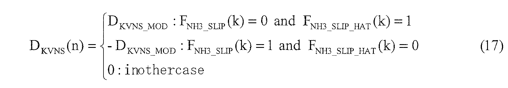
- As shown in the following formula (18), similarly to the above-mentioned
TYPE 1, the update amount DKVNS is set to a predetermined amount that is not "0" while there is a difference between the time for which the slip determination flag FNH3 SLIP is set to "1" and the time for which the slip estimation flag FNH3 SLIP HAT is set to "1" inTYPE 2 as well. However, withTYPE 2, in addition to a case of there being a difference in the time periods for which the two flags FNH3 SLIP and FNH3 SLIP HAT are set to "1", the update amount DKVNS is set to a value that is not "0" only in a case in which a flag FVNS_CAL is set to "1".
- The flag FVNS CAL defining this computing timing is set based on the following formula (19). In other words, the flag FVNS CAL is set to "1" from "0" when the slip determination flag FNH3 SLIP is set to "1" from "0", or when the slip estimation flag FNH3 SLIP HAT is set to "1" from "0". Thereafter, the flag FVNS CAL is also reset to "0" in response to the slip determination flag FNH3_SLIP being reset to "0".

- Incidentally, under operating conditions in which the temperature change of the selective reduction catalyst is sharp, error easily arises between the slip determination flag FNH3 SLIP and the slip estimation flag FNH3_SLIP_HAT. This is because the estimation flag FNH3_SLIP_HAT is set based on the storage capacity estimated value STUREA MAX, which changes greatly in response to temperature change. As explained above, with
TYPE 2, since the update amount DKVNS is set to a value that is not "0" only while the flag FVNS CAL is set to "1" during the time when there is a difference in the time periods for which the two flags FNH3 SLIP and FNH3_SLIP_HAT are set to "1", the storage capacity is considered to be corrected by a gain that is small compared toTYPE 1. Therefore, withTYPE 2, the correction precision of the storage capacity under conditions in which the temperature change of the selective reduction catalyst is sharp can be improved in particular, compared toTYPE 1. -
FIG. 13 is a view showing configurations of three weighting functions Wi (i=1, 2, 3) with the output values TSCR of the catalyst temperature sensor as the domains. - As shown in
FIG. 13 , three regions overlapping each other are set in the domains, and the three weighting functions Wi are set so as to have values that are not 0 in these regions. - More specifically, the domains are divided into region 1 (T0, T1), region 2 (T0, T2), and region 3 (T1, T2). Herein, T0<T1<T2 is defined. Therefore,
region 1 andregion 2 overlap in the interval (T0, T1), andregion 2 andregion 3 overlap in the interval (T1, T2). - The weighting function W1 is set so as to have a value that is not 0 in region 1 (T0, T1). More specifically, the weighting function W1 is set so as to decrease from 1 to 0 in the interval (T0, T1).
- The weighting function W2 is set so as to have a value that is not 0 in region 2 (T0, T2). More specifically, the weighting function W2 is set so as to rise from 0 to 1 in the interval (T0, T1) and is set so as to decrease from 1 to 0 in the interval (T1, T2). Therefore, the weighting function W1 and the weighting function W2 intersect in the middle of the interval (T0, T1).
- The weighting function W3 is set so as to have a value that is not 0 in region 3 (T1, T2). More specifically, the weighting function W3 is set so as to rise from 0 to 1 in the interval (T1, T2). Therefore, the weighting function W2 and the weighting function W3 intersect in the middle of the interval (T1, T2).
- It should be noted that the number regions defining and the number of weighting functions is not limited to 3, and may be 4 or more. The estimated value of the exhaust volume may be added as a domain defining the weighting functions. In addition, it is preferable to set to the distribution of weighting functions so as to be dense in regions in which the variation amount is large.
- Moreover, the weighting functions Wi configured as above are normalized so that a sum total function thereof becomes 1 irrespective of the catalyst temperature sensor output value TSCR, as shown in the following formula (20).

- Returning to
FIG. 12 , for each weighting function Wi, a value is output by the weightingfunction setting portion 362 according to the catalyst temperature sensor output value TSCR. - With the
first multiplier 363, the products of multiplying the update amount DKVNS calculated by the updateamount calculating portion 361 by each weighting function value output from the weightingfunction setting portion 362 are output to the local correctionvalue calculating portion 364. - With the local correction
value calculating portion 364, first, a forgetting factor LAMBDAi (i=1, 2, 3) for every local correction value KVNSi is set as shown in the following formula (21). - More specifically, the forgetting factor LAMBDAi is set to a setting value LAMBDAFGT_H (e.g., 0.995) for excess time at an excess time at which the local correction value KVNSi is larger than the threshold value KVSFGT H (e.g., 1.2). The forgetting factor LAMBDAi is set to a setting value LAMBDAFGT_L (e.g., 0.990) for deficient time at a deficient time at which the local correction value KVNSi is smaller than the threshold value KVSFGT L (e.g., 0.1). In addition, in a case of the local correction value KVNSi being between the above-mentioned threshold value KVSFGT H and threshold value KVSFGT L, the forgetting factor LAMBDAi is set to "1". It should be noted that the threshold value KVSFGT L is set to be smaller than a degradation determination threshold value KVNSAGED described later, which is set in order to determine degradation of the selective reduction catalyst.

- Next, the local correction value KVNSi is updated based on the forgetting factor LAMBDAi (n) thus calculated, the previous value KVNSi (n-1) of the local correction value, the weighting function value Wi (n), and the update amount DKVNS (n).
- The local correction value KVNSi (n) is calculated using the following formula (22). It should be noted that, in a case of the map determining the reference value STUREA_MAX_BS of the storage capacity being constructed using a selective reduction catalyst that is a new article, the initial value of the local correction value KVNSi is defined as "1". In addition, in a case of correcting the estimated value STUREA MAX by adding the storage capacity correction value KVNS to the reference value STUREA MAX BS, the initial value of the local correction value KVNSi is defined as "0".

- With the
second multiplier 365 and theadder 366, the sum total of the products of the local correction values KVNSi (n) and the weighting function values Wi(n) is calculated as shown in the following formula (23), and this is set as the storage capacity correction value KVNS(n).
- With the catalyst
degradation determination unit 37, degradation of the selective reduction catalyst is determined by determining the degradation determination flag FSCR AGD, based on at least any of the parameters correlating to the degradation progression extent of the selective reduction catalyst such as the estimated value STUREA of the storage capacity, local correction value KVNSi, and storage capacity correction value KVNS. It should be noted that three variations are considered for the specific sequence of determining the degradation of the catalyst. Hereinafter, sequences of the three variations ofTYPE 1,TYPE 2 andTYPE 3 will each be explained. - With
TYPE 1, the degradation determination threshold value KVNSAGED for determining degradation of the selective reduction catalyst is set for the storage capacity correction value KVNS. Then, in a case of the storage capacity correction value KVNS becoming smaller than the degradation determination threshold value KVNSAGED, it is determined that the selective reduction catalyst has degraded, and the degradation determination flag FSCR AGD is set to "1" from "0".
- With
TYPE 2, the degradation determination threshold value KVNSAGED is set for a second component KVNS2, which is defined throughout the entire temperature region, among the local correction value KVNSi. Then, in a case of the second component KVNS2 of the local correction value becoming smaller than the degradation determination threshold value KVNSAGED, it is determined that the selective reduction catalyst has degraded, and the degradation determination flag FSCR AGD is set to "1" from "0".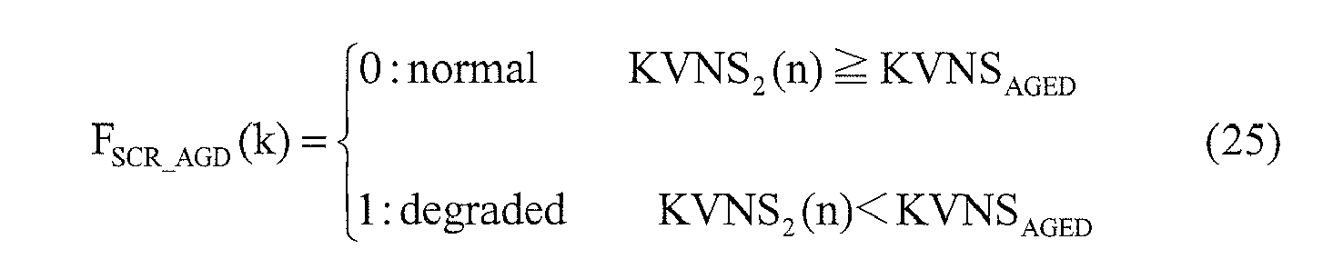
- With
TYPE 3, the degradation determination threshold value STUREA AGED for determining degradation of the selective reduction catalyst is set for the estimated value STUREA MAX of the storage capacity. Then, in a case of the storage capacity estimated value STUREA_MAX become smaller than the degradation determination threshold value STUREA AGED, it is determined that the selective reduction catalyst has degraded, and the degradation determination flag FSCR AGD is set to "1" from "0".
- Next, a specific sequence of urea injection control will be explained while referring to
FIG. 14 . -
FIG. 14 is a flowchart showing a sequence of urea injection control executed by an ECU. - In Step S1, it is distinguished whether a urea fault flag FUREANG is "1". This urea fault flag FUREANG is set to "1" when it is determined that the urea injection device has failed in determination processing, which is not illustrated, and is set to "0" at times except for this. In a case of this determination being YES, Step S8 is advanced to, and after the urea injection amount GUREA has been set to "0", this processing ends. In a case of this determination being NO, Step S2 is advanced to.
- In Step S2, it is distinguished whether the urea remaining amount QUREA is less than a predetermined value QREF. This urea remaining amount QUREA indicates a remaining amount of urea water in the urea tank, and is calculated based on an output of the urea level sensor. In a case of this determination being YES, Step S3 is advanced to, and in a case of being NO, Step S4 is advanced to.
- In Step S3, the urea remaining amount warning light is illuminated, and Step S8 is advanced to, and after the urea injection amount GUREA has been set to "0", this processing ends.
- In Step S4, it is distinguished whether a catalyst warm-up timer value TMAST is larger than a predetermined value TMLMT. This catalyst warm-up timer value TMAST is a value keeping the warm-up time of the selective reduction catalyst after engine startup. In a case of this determination being YES, Step S5 is advanced to. In a case of this determination being NO, Step S8 is advanced to, and after the urea injection amount GUREA has been set to "0", this processing ends.
- In Step S5, it is distinguished whether a sensor fault flag FSENNG is "0". This sensor fault flag FSENNG is set to "1" when it is determined that the ammonia sensor or the catalyst temperature sensor has failed in the determination processing, which is not illustrated, and is set to "0" at times except for this. In a case of this determination being YES, Step S6 is advanced to. In a case of this determination being NO, Step S8 is advanced to, and after the urea injection amount GUREA has been set to "0", this processing ends.
- In Step S6, it is distinguished whether an ammonia sensor activity flag FNH3ACT is 1. This ammonia sensor activity flag FNH3ACT is set to "1" when it is determined that the ammonia sensor has reached an active state in determination processing, which is not illustrated, and is set to "0" at times except for this. In a case of this determination being YES, Step S7 is advanced to. In a case of this determination being NO, Step S8 is advanced to, and after the urea injection amount GUREA has been set to "0", this processing ends.
- In Step S7, it is distinguished whether the catalyst temperature sensor output value TSCR is larger than a predetermined value TSCR ACT. In a case of this determination being YES, it is determined that the selective reduction catalyst has been activated, and Step S9 is advanced to. In a case of this determination being NO, it is determined that the selective reduction catalyst has not been activated yet and that urea injection should be stopped, Step S8 is advanced to, and after the urea injection amount GUREA has been set to "0", this processing ends.
- In Step S9, the slip estimation flag FNH3_SLIP_HAT and the storage capacity estimated value KVNS are calculated by the aforementioned state estimation unit and storage capacity correction unit based on formulas (13) to (23).
- In Step S10, the urea injection amount GUREA is calculated by the slip determination portion, state estimation unit, reference injection amount calculating portion, and switching injection amount calculating portion based on formulas (1) to (12), and Step S11 is advanced to.
- In Step S11, it is distinguished whether the catalyst temperature sensor output value TSCR is within a range of the upper limit value TSCR H and the lower limit value TSCR L. In a case of this determination being YES, it is determined to be a state suited for determining degradation of the selective reduction catalyst, and Step S12 is advanced to. In a case of this determination being NO, this processing ends immediately. It should be noted that the upper limit value TSCR H is set to 300°C and the lower limit value TSCR L is set to 230°C, for example.
- In Step S12, the degradation determination flag FSCR AGD is updated by the catalyst degradation determination unit based on any of formulas (24), (25) and (26), and Step S13 is advanced to.
- In Step S13, it is distinguished whether the degradation determination flag TSCR AGD is "1". In a case of this determination being YES, Step S14 is advanced to, and after the catalyst degradation warning light has been illuminated, this processing ends. In a case of this determination being NO, this processing ends immediately.
- Next, simulation results of the urea injection control of the present embodiment will be explained in detail while referring to
FIGS. 15 to 19 . - Herein, taking into account of the two problems exemplified in the above-mentioned (1) and (2), simulation was performed under four different types of conditions. More specifically,
CASE 1 is a case in which a selective reduction catalyst that is a new article is used and there is no gain variation in the ammonia sensor,CASE 2 is a case in which the selective reduction catalyst that is a new article is used and there is gain variation in the ammonia sensor,CASE 3 is a case in which a degraded selective reduction catalyst is used and there is no gain variation in the ammonia sensor, and CASE 4 is a case in which a degraded selective reduction catalyst is used and there is gain variation in the ammonia sensor. It should be noted that, for the degraded selective reduction catalyst, a catalyst for which the storage capacity had declined by 30% relative to the new article was used. In addition, a case in which there is gain variation in the ammonia sensor more specifically indicates a case in which the gain has been made to decline by 50%.[Table.1] STATE OF THE CATALYST GAIN VARIATION OF NH3 SENSOR CASE 1 NEW ARTICLE OFF CASE 2NEW ARTICLE ON CASE 3DEGRADED ARTICLE OFF CASE 4 DEGRADED ARTICLE ON -
FIG. 15 shows the simulation results ofCASE 1. It should be noted that, in the graph of the NOx amount inFIG. 15 , the variation in the NOx amount discharged to outside the system indicated by the dotted line is substantially the same as the variation in the NOx amount discharged to downstream of the selective reduction catalyst indicated by the thin solid line. In addition, in the graph of the ammonia amount, the ammonia amount discharged to outside the system indicated by the thin solid line is substantially constant at "0". Moreover, in the graph of the storage amount, the estimated value of the storage capacity indicated by the thick solid line shows variation substantially the same as the actual storage capacity indicated by the dashed line, and the storage amount indicated by the thin solid line shows variation substantially that same as the actual storage amount indicated by the dotted line. -
CASE 1 is considered to be a state in which the error of the control system is the smallest, since the selective reduction catalyst is a new article and there is also no gain variation of the ammonia sensor. Therefore, although ammonia slip by the selective reduction catalyst occurs with the operating state of the engine becoming high load, ammonia discharged to outside the system amounts to nothing. In addition, since the actual storage amount is controlled to near the actual storage capacity apart for the duration in which the storage capacity is temporarily increased from low load operation being performed intermittently, the NOx purification rate of the selective reduction catalyst is also maintained to be high. - Moreover, the storage capacity correction value KVNS is maintained at "1", a result of which the error in the estimated value STUREA MAX of the storage capacity relative to the actual storage capacity is also small. This fact is consistent with using a selective reduction catalyst that is a new article.
- According to the present embodiment, it is possible to prevent ammonia from being discharged to outside the system while maintaining the NOx purification rate to be high, in spite of using the output value of the ammonia sensor as binary information, as above.
-
FIG. 16 shows the simulation results ofCASE 2. It should be noted that, in the graph of the NOx amount in.FIG. 16 , the variation in the NOx amount discharged to outside the system indicated by the dotted line is substantially the same as the variation in the NOx amount discharged to downstream of the selective reduction catalyst indicated by the thin solid line. In addition, in the graph of the ammonia amount, the ammonia amount discharged to outside the system indicated by the thin solid line is substantially constant at "0". Moreover, in the graph of the storage amount, the estimated value of the storage capacity indicated by the thick solid line shows variation substantially the same as the actual storage capacity indicated by the dashed line, and the storage amount indicated by the thin solid line shows variation substantially that same as the actual storage amount indicated by the dotted line. - Although
CASE 2 is a case of a state in which gain variation in the ammonia sensor occurs, the effect thereof is small due to using the output value of the ammonia sensor as binary information. Therefore, the simulation results ofCASE 2 are substantially the same as the simulation results ofCASE 1. Therefore, it has been verified that, according to the present embodiment, even in a case of gain variation in the ammonia sensor having occurred, it is possible to prevent ammonia from discharging to outside the system, while stably maintaining the NOx purification rate to be high. -
FIG. 17 shows the simulation results ofCASE 3. It should be noted that, in the graph of the NOx amount inFIG. 17 , the variation in the NOx amount discharged to outside the system indicated by the dotted line is substantially the same as the variation in the NOx amount discharged to downstream of the selective reduction catalyst indicated by the thin solid line. In addition, in the graph of the ammonia amount, the ammonia amount discharged to outside the system indicated by the thin solid line is substantially constant at "0". - Since
CASE 3 is a state in which the selective reduction catalyst has degraded, immediately after operation start, the estimated value STUREA MAX of the storage capacity and the estimated value STUREA of the storage amount deviate greatly from the actual storage capacity and the actual storage amount. However, the storage capacity correction value KVNS will gradually decrease from "1", and can be brought to the actual value along with the estimated value STUREA MAX of the storage capacity and the estimated value STUREA of the storage amount by adaptively correcting to a degraded state. Therefore, it has been verified that, according to the present embodiment, even in a state in which the selective reduction catalyst has degraded, it is possible to prevent ammonia from being discharged to outside the system, while stably maintaining the NOx purification rate to be high. -
FIG. 18 shows the simulation results of CASE 4. It should be noted that, in the graph of the NOx amount inFIG. 18 , the variation in the NOx amount discharged to outside the system indicated by the dotted line is substantially the same as the variation in the NOx amount discharged to downstream of the selective reduction catalyst indicated by the thin solid line. In addition, in the graph of the ammonia amount, the ammonia amount discharged to outside the system indicated by the thin solid line is substantially constant at "0". - CASE 4 is a state in which gain variation in the ammonia sensor occurs and the selective reduction catalyst has degraded, and is considered to be the state in which the error of the control system is the largest. However, since the output value of the ammonia sensor is used as binary information, the effect of there being gain variation in the ammonia sensor is small. Therefore, the simulation results of CASE 4 are substantially the same as the simulation results of
CASE 3. Therefore, it has been verified that, according to the present embodiment, it has robustness against gain variation of the ammonia sensor and degradation of the selective reduction catalyst. - According to the present embodiment, there are the following effects.
- (1) The reference injection amount GUREA BS is calculated based on a parameter (engine revolution speed NE, load parameter TRQ) correlating to the operating state of the engine. The urea injection amount GUREA is decided by decreasing in amount, relative to such a reference injection amount GUREA BS, in response to having determined that ammonia slip has occurred, and increasing in amount in response to the storage amount estimated value STUREA falling below the switch storage amount STUREA SW. With this, it is possible to continuously maintain the NOx purification rate of the selective reduction catalyst to be high, since the storage amount estimated value STUREA of the selective reduction catalyst can be controlled so as to oscillate between the switch storage amount STUREA SW and the storage capacity estimated value STUREA MAX, while supplying ammonia of an amount required to purify the exhaust according to the operating state of the engine. In addition, at this time, since the occurrence of ammonia slip of the selective reduction catalyst can be done intermittently, it is possible to control the occurrence of ammonia slip while maintaining the NOx purification rate of the selective reduction catalyst to be high.
- In addition, binary determination results output from the slip determination unit, and not the output value NH3CONS of the ammonia sensor itself, are used in order to determine the urea injection amount GUREA. Therefore, the slip determination portion determines the existence of the occurrence of ammonia slip based on the output value NH3CONS of the ammonia sensor. In addition, the determination result of such an existence of ammonia is considered to not be greatly influenced by the gain variation of the ammonia sensor. Therefore, it is possible to determine the urea injection amount GUREA without being affected by the gain variation of the ammonia sensor.
- (2) The estimated value STUREA MAX of the storage capacity is calculated, and the above-mentioned switch storage amount STUREA SW is set based on this estimated value STUREA MAX of the storage capacity. With this, it is possible to suppress the occurrence of ammonia slip to a minimum, while stably maintaining the NOx purification rate to be high in accordance with the actual state of the selective reduction catalyst, since the switch storage amount STUREA SW can be appropriately set according to the storage capacity, which changes depending on the temperature and extent of degradation of the selective reduction catalyst.
- (3) The estimated value STUREA MAX of the storage capacity is corrected according to the difference between the occurrence time of ammonia slip determined based on the output value NH3CONS of the ammonia sensor and the occurrence time of ammonia slip determined based on the estimated value STUREA of the storage amount. With this, it is possible to further improve the stability of the NOx purification rate and the ability to suppress ammonia slip, since the estimated value STUREA MAX of the storage capacity can be brought to the actual storage capacity, even in a case of material inconsistency and aging in the selective reduction catalyst and ammonia sensor occurring.
- (4) The plurality of local correction values KVNSi are updated based on the difference between the occurrence time of ammonia slip determined by the slip determination portion and the occurrence time of ammonia slip determined by the state estimation unit. Then, the sum total of products of the weighting function values Wi (n) according to the output value TSCR of the catalyst temperature sensor and the above-mentioned local correction values KVNSi (n) is set as the storage capacity correction value KVNS, and the estimated value STUREA MAX of the storage capacity is corrected based on this storage capacity correction value KVNS. With this, it is possible to adaptively correct the estimated value STUREA MAX of the storage capacity so that the time for which ammonia slip actually occurred and the estimated time for which ammonia slip occurred are in agreement.
- (5) By determining degradation of the selective reduction catalyst by the catalyst degradation determination unit, it is possible for the operator to recognize that the selective reduction catalyst has degraded.
- It should be noted that the present invention is not limited to the aforementioned embodiment, and various modification are possible.
- Although the estimated value STUREA of the storage amount and the estimated value STUREA MAX of the storage capacity of the selective reduction catalyst were set as values having a scale of the amount of urea water in the above-mentioned embodiment, it is not limited thereto. For example, similar effects are exerted even if set to values having a scale of the amount of ammonia generated from this urea water.
- In addition, although an example was exemplified in which the present invention was applied to an exhaust purification system of urea addition-type that uses ammonia as a reducing agent and supplies urea water as an additive to be the source of this reducing agent in the above-mentioned embodiment, it is not limited thereto.
- For example, ammonia may be directly supplied without supplying urea water to generate ammonia from this urea water. In addition, the additive to be the source of ammonia is not limited to urea water, and another additive may be used. Moreover, the reducing agent for reducing NOx is not limited to ammonia. The present invention can be applied to an exhaust purification system using hydrocarbons in place of ammonia, for example, as the reducing agent for reducing NOx.
- An exhaust purification system is provided that can continuously maintain a NOx purification rate to be high while suppressing the occurrence of ammonia slip. The exhaust purification system includes a
slip determination portion 34 that determines the occurrence of ammonia slip based on an output value NH3CONS of anammonia sensor 26. A reference injectionamount calculating portion 31 calculates a reference injection amount GUREA BS based on a parameter correlating to an operating state of an engine. A switching injectionamount calculating portion 32 decreases in amount a urea injection amount GUREA by setting a switching injection amount GUREA SW to a negative value in response to having determined that ammonia slip has occurred, and increases in amount the injection amount GUREA by setting the switching injection amount GUREA SW to a positive value in response to a storage amount estimated value STUREA having fallen below a predetermined switch storage amount STUREA SW.
Claims (6)
- An exhaust purification system (2) for an internal combustion engine (1) equipped with a selective reduction catalyst (23) provided in an exhaust channel (11) of an internal combustion engine (1) that reduces NOx in exhaust flowing through the exhaust channel (11) under the presence of a reducing agent, and
a reducing agent supply means (25) for supplying a reducing agent or an additive serving as a source to the selective reduction catalyst (23), the system (2) comprising:a reducing agent detection means (26) for detecting a reducing agent amount or reducing agent concentration of exhaust in the exhaust channel (11) on a downstream side of the selective reduction catalyst (23);a slip determination means (34) for determining an occurrence of reducing agent slip in the selective reduction catalyst (23) based on an output value (NH3CONS) of the reducing agent detection means (26);a storage amount estimation means (35) for calculating an estimated value (STUREA) of a storage amount, with an amount of reducing agent stored in the selective reduction catalyst (23) as the storage amount; anda supply amount determination means (31, 32, 33) for determining a supply amount (GUREA) of the reducing agent supply means (25),wherein the supply amount determination means (31, 32, 33) determines a supply amount (GUREA) by decreasing in amount, relative to a reference supply amount (GUREA BS) calculated based on a parameter (NE, TRQ) correlating to an operating state of the internal combustion engine (1), in response to having determined that the reducing agent slip has occurred, and increasing in amount in response to an estimated amount of the storage amount falling below a predetermined switch determination value (STUREA SW). - An exhaust purification system (2) for an internal combustion engine (1) according to claim 1, further comprising a storage capacity estimation means (35, 36) for calculating an estimated value (STUREA MAX) of a storage capacity, with an amount of reducing agent that can be stored by the selective reduction catalyst (23) as the storage capacity,
wherein the switch determination value (STUREA SW) is set based on the estimated value (STUREA MAX) of the storage capacity. - An exhaust purification system (2) for an internal combustion engine (1) according to claim 2, further comprising a slip estimation means (35) for determining the occurrence of reducing agent slip based on the estimated value (STUREA) of the storage amount,
wherein the storage capacity estimation means (35, 36) corrects the estimated value (STAREA_WAX) of the storage capacity based on a difference between an occurrence time of reducing agent slip determined by way of the slip determination means (34) and an occurrence time of reducing agent slip determined by way of the slip estimation means (35). - An exhaust purification system (2) for an internal combustion engine (1) equipped with a selective reduction catalyst (23) provided in an exhaust channel (11) of an internal combustion engine (1) that reduces NOx in exhaust flowing through the exhaust channel (11) under the presence of reducing agent, and
a reducing agent supply means (25) for supplying a reducing agent or an additive serving as a source of a reducing agent to the selective reduction catalyst (23), the system (2) comprising:a reducing agent detection means (26) for detecting a reducing agent amount or reducing agent concentration of exhaust in the exhaust channel (11) on a downstream side of the selective reduction catalyst (23);a storage amount estimation means (35) for calculating an estimated value (STUREA) of a storage amount, with an amount of reducing agent stored in the selective reduction catalyst (23) as the storage amount;a storage capacity estimation means (35, 36) for calculating an estimated value (STUREA MAX) of a storage capacity, with an amount of reducing agent that can be stored by the selective reduction catalyst (23) as the storage capacity;a slip determination means (34) for determining an occurrence of reducing agent slip in the selective reduction catalyst (23) based on an output value (NH3CONS) of the reducing agent detection means (26);a slip estimation means (35) for determining the occurrence of the reducing agent slip based on the estimated value (STUREA) of the storage amount; anda supply amount determination means (31, 32, 33) for determining a supply amount (GUREA) of the reducing agent supply means (25) based on a parameter (NE, TRQ) correlating to an operating state of the internal combustion engine (1), the estimated value (STUREA) of the storage amount, and the estimated value (STUREA MAX) of the storage capacity,wherein the storage capacity estimation means (35, 36) corrects the estimated value (STUREA) of the storage capacity based on a difference between an occurrence time of reducing agent slip determined by way of the slip determination means (34) and an occurrence time of reducing agent slip determined by way of the slip estimation means (35). - An exhaust purification system (2) for an internal combustion engine (1) according to claim 4,
wherein a plurality of weighting functions (Wi) and a plurality of correction values (KVNSi) are set for a plurality of regions set for temperature of the selective reduction catalyst, and
wherein the storage capacity estimation means (35, 36) updates the plurality of correction values (KVNSi) based on a difference between an occurrence time of reducing agent slip determined by way of the slip determination means (34) and an occurrence time of reducing agent slip determined by way of the slip estimation means (35), sets a sum total of products of the plurality of correction values thus updated and values of the plurality of weighting functions according to the temperature of the selective reduction catalyst (23) as a correction coefficient (KVNS), and corrects the estimated value (STUREA MAX) of the storage capacity based on the correction coefficient (KVNS). - An exhaust purification system (2) for an internal combustion engine (1) according to claim 5, further comprising a catalyst degradation determination means (37) for determining degradation of the selective reduction catalyst (23) based on at least any of the estimated value (STUREA MAX) of the storage capacity, the plurality of correction values (KVNSi), and the correction coefficient (KVNS).
Applications Claiming Priority (1)
| Application Number | Priority Date | Filing Date | Title |
|---|---|---|---|
| JP2009252028A JP5037587B2 (en) | 2009-11-02 | 2009-11-02 | Exhaust gas purification system for internal combustion engine |
Publications (2)
| Publication Number | Publication Date |
|---|---|
| EP2317091A1 true EP2317091A1 (en) | 2011-05-04 |
| EP2317091B1 EP2317091B1 (en) | 2012-05-09 |
Family
ID=43528357
Family Applications (1)
| Application Number | Title | Priority Date | Filing Date |
|---|---|---|---|
| EP10189618A Not-in-force EP2317091B1 (en) | 2009-11-02 | 2010-11-02 | Exhaust purification system for internal combustion engine |
Country Status (4)
| Country | Link |
|---|---|
| US (1) | US8813477B2 (en) |
| EP (1) | EP2317091B1 (en) |
| JP (1) | JP5037587B2 (en) |
| AT (1) | ATE557171T1 (en) |
Cited By (6)
| Publication number | Priority date | Publication date | Assignee | Title |
|---|---|---|---|---|
| WO2014005850A1 (en) * | 2012-07-04 | 2014-01-09 | Emitec Gesellschaft Für Emissionstechnologie Mbh | Method for determining reducing agent slip |
| EP2684597A1 (en) | 2012-07-14 | 2014-01-15 | Deutz AG | Method for reducing nitrogen oxides in diesel engine exhaust |
| EP2947289A1 (en) * | 2014-05-23 | 2015-11-25 | Toyota Jidosha Kabushiki Kaisha | Abnormality diagnosis apparatus for exhaust gas purification apparatus |
| FR3067058A1 (en) * | 2017-06-01 | 2018-12-07 | Peugeot Citroen Automobiles Sa | METHOD FOR MANAGING REDUCING AGENT INJECTION IN A SELECTIVE CATALYTIC REDUCTION SYSTEM |
| WO2020057768A1 (en) | 2018-09-20 | 2020-03-26 | Deutz Aktiengesellschaft | Dynamic detection of ammonia excess by means of a software algorithm in order to eliminate the ammonia sensor |
| AT522752A1 (en) * | 2019-07-05 | 2021-01-15 | Avl List Gmbh | Method for functional testing of an exhaust gas aftertreatment system of an internal combustion engine and an exhaust gas aftertreatment system |
Families Citing this family (12)
| Publication number | Priority date | Publication date | Assignee | Title |
|---|---|---|---|---|
| CN103748325B (en) * | 2011-04-05 | 2017-03-15 | 卡明斯散发控制技术公司 | Systems, methods and apparatus for aftertreatment system monitoring |
| JP5770585B2 (en) * | 2011-09-28 | 2015-08-26 | 本田技研工業株式会社 | Air-fuel ratio control device for internal combustion engine |
| JP2014080881A (en) | 2012-10-15 | 2014-05-08 | Honda Motor Co Ltd | Exhaust emission control system for internal combustion engine |
| US8935915B2 (en) * | 2012-11-05 | 2015-01-20 | International Engine Intellectual Property Company, Llc. | Ammonia storage on an SCR catalyst |
| JP5842805B2 (en) * | 2012-12-28 | 2016-01-13 | 株式会社デンソー | Urea water addition controller |
| US9091194B2 (en) * | 2013-08-05 | 2015-07-28 | GM Global Technology Operations LLC | Temperature gradient correction of ammonia storage model |
| US10082060B2 (en) * | 2015-12-17 | 2018-09-25 | General Electric Company | Enhanced performance of a gas turbine |
| US10247076B2 (en) * | 2017-04-07 | 2019-04-02 | GM Global Technology Operations LLC | Exhaust treatment system including ammonia storage control system |
| JP6339728B2 (en) * | 2017-07-10 | 2018-06-06 | ボッシュ株式会社 | Control device, exhaust purification device for internal combustion engine, and control method for exhaust purification device |
| FR3069574B1 (en) * | 2017-07-25 | 2019-08-02 | Continental Automotive France | METHOD FOR ADAPTING A QUANTITY OF REDUCING AGENT FOR GAS NITROGEN OXIDE DEPOLLUTION IN AN ENGINE EXHAUST LINE |
| US10634032B2 (en) * | 2017-12-15 | 2020-04-28 | GM Global Technology Operations LLC | Method and apparatus for monitoring an exhaust aftertreatment system for an internal combustion engine |
| US20250198321A1 (en) * | 2023-12-13 | 2025-06-19 | Cummins Inc. | Systems and methods to assess state-of-health of an exhaust gas constituent capture device |
Citations (7)
| Publication number | Priority date | Publication date | Assignee | Title |
|---|---|---|---|---|
| JP2004037378A (en) | 2002-07-05 | 2004-02-05 | Ngk Spark Plug Co Ltd | Ammonia sensor and control method thereof |
| JP2004100700A (en) | 2002-09-04 | 2004-04-02 | Ford Global Technologies Llc | Exhaust emission control and diagnostics |
| JP2005114355A (en) | 2002-09-25 | 2005-04-28 | Ngk Spark Plug Co Ltd | Ammonia sensor |
| JP2006274986A (en) | 2005-03-30 | 2006-10-12 | Mitsubishi Fuso Truck & Bus Corp | Exhaust gas aftertreatment device |
| DE102008017543A1 (en) * | 2007-04-10 | 2008-10-23 | GM Global Technology Operations, Inc., Detroit | Dosing module for selective catalytic reduction in vehicle exhaust system has a dose adjustment module that receives an ammonia signal and determines a dose adjustment based on the ammonia signal |
| DE102007040439A1 (en) * | 2007-08-28 | 2009-03-05 | Daimler Ag | Operating and diagnostic procedures for an SCR exhaust aftertreatment system |
| JP2009252028A (en) | 2008-04-08 | 2009-10-29 | Nec Electronics Corp | Automatic transistor arrangement device, method, and program |
Family Cites Families (12)
| Publication number | Priority date | Publication date | Assignee | Title |
|---|---|---|---|---|
| JP2000177741A (en) * | 1998-12-16 | 2000-06-27 | Nissei Asb Mach Co Ltd | Handle-equipped synthetic resin container, and handle for container |
| DE10100420A1 (en) * | 2001-01-08 | 2002-07-11 | Bosch Gmbh Robert | Method and device for controlling an exhaust gas aftertreatment system |
| JP4089201B2 (en) * | 2001-10-24 | 2008-05-28 | トヨタ自動車株式会社 | Exhaust gas purification management method and apparatus for internal combustion engine |
| US6981368B2 (en) * | 2002-11-21 | 2006-01-03 | Ford Global Technologies, Llc | Exhaust gas aftertreatment systems |
| JP3943044B2 (en) * | 2003-03-28 | 2007-07-11 | 日産ディーゼル工業株式会社 | Engine exhaust purification system |
| JP2006125247A (en) * | 2004-10-27 | 2006-05-18 | Hitachi Ltd | Engine exhaust gas purification method and exhaust gas purification device |
| DE102007009824A1 (en) | 2006-03-03 | 2007-09-27 | Ford Global Technologies, LLC, Dearborn | System and method for detecting reductant storage |
| US7886527B2 (en) * | 2007-04-10 | 2011-02-15 | Gm Global Technology Operations, Inc. | Reductant injection control strategy |
| JP5052208B2 (en) * | 2007-05-24 | 2012-10-17 | トヨタ自動車株式会社 | Exhaust gas purification device for internal combustion engine |
| WO2009128169A1 (en) * | 2008-04-18 | 2009-10-22 | 本田技研工業株式会社 | Exhaust purification apparatus for internal combustion engine |
| US8397303B2 (en) | 2008-04-18 | 2013-03-12 | Panasonic Corporation | Memory controller, nonvolatile storage system, and data management method |
| JP5177413B2 (en) * | 2008-09-24 | 2013-04-03 | マツダ株式会社 | Engine exhaust purification system |
-
2009
- 2009-11-02 JP JP2009252028A patent/JP5037587B2/en not_active Expired - Fee Related
-
2010
- 2010-11-01 US US12/917,179 patent/US8813477B2/en active Active
- 2010-11-02 EP EP10189618A patent/EP2317091B1/en not_active Not-in-force
- 2010-11-02 AT AT10189618T patent/ATE557171T1/en active
Patent Citations (7)
| Publication number | Priority date | Publication date | Assignee | Title |
|---|---|---|---|---|
| JP2004037378A (en) | 2002-07-05 | 2004-02-05 | Ngk Spark Plug Co Ltd | Ammonia sensor and control method thereof |
| JP2004100700A (en) | 2002-09-04 | 2004-04-02 | Ford Global Technologies Llc | Exhaust emission control and diagnostics |
| JP2005114355A (en) | 2002-09-25 | 2005-04-28 | Ngk Spark Plug Co Ltd | Ammonia sensor |
| JP2006274986A (en) | 2005-03-30 | 2006-10-12 | Mitsubishi Fuso Truck & Bus Corp | Exhaust gas aftertreatment device |
| DE102008017543A1 (en) * | 2007-04-10 | 2008-10-23 | GM Global Technology Operations, Inc., Detroit | Dosing module for selective catalytic reduction in vehicle exhaust system has a dose adjustment module that receives an ammonia signal and determines a dose adjustment based on the ammonia signal |
| DE102007040439A1 (en) * | 2007-08-28 | 2009-03-05 | Daimler Ag | Operating and diagnostic procedures for an SCR exhaust aftertreatment system |
| JP2009252028A (en) | 2008-04-08 | 2009-10-29 | Nec Electronics Corp | Automatic transistor arrangement device, method, and program |
Cited By (13)
| Publication number | Priority date | Publication date | Assignee | Title |
|---|---|---|---|---|
| WO2014005850A1 (en) * | 2012-07-04 | 2014-01-09 | Emitec Gesellschaft Für Emissionstechnologie Mbh | Method for determining reducing agent slip |
| US9500111B2 (en) | 2012-07-04 | 2016-11-22 | Emitec Gesellschaft Fuer Emissionstechnologie Mbh | Method for determining reducing agent slippage and motor vehicle employing the method |
| RU2606292C2 (en) * | 2012-07-04 | 2017-01-10 | Эмитек Гезельшафт Фюр Эмиссионстехнологи Мбх | Method of reducing agent leakage determining |
| EP2684597A1 (en) | 2012-07-14 | 2014-01-15 | Deutz AG | Method for reducing nitrogen oxides in diesel engine exhaust |
| US9206722B2 (en) | 2012-07-14 | 2015-12-08 | Deutz Ag | Method for reducing nitrogen oxide levels in diesel engine exhaust gases |
| EP2947289A1 (en) * | 2014-05-23 | 2015-11-25 | Toyota Jidosha Kabushiki Kaisha | Abnormality diagnosis apparatus for exhaust gas purification apparatus |
| FR3067058A1 (en) * | 2017-06-01 | 2018-12-07 | Peugeot Citroen Automobiles Sa | METHOD FOR MANAGING REDUCING AGENT INJECTION IN A SELECTIVE CATALYTIC REDUCTION SYSTEM |
| WO2020057768A1 (en) | 2018-09-20 | 2020-03-26 | Deutz Aktiengesellschaft | Dynamic detection of ammonia excess by means of a software algorithm in order to eliminate the ammonia sensor |
| DE102018007421A1 (en) * | 2018-09-20 | 2020-03-26 | Deutz Ag | Dynamic excess ammonia detection using a software algorithm to eliminate the ammonia sensor |
| DE102018007421B4 (en) * | 2018-09-20 | 2021-07-01 | Deutz Ag | Dynamic ammonia excess detection using a software algorithm to eliminate the ammonia sensor |
| US11434802B2 (en) | 2018-09-20 | 2022-09-06 | Deutz Aktiengesellschaft | Dynamic excess ammonia detection with the aid of a software algorithm in order to eliminate the ammonia sensor |
| AT522752A1 (en) * | 2019-07-05 | 2021-01-15 | Avl List Gmbh | Method for functional testing of an exhaust gas aftertreatment system of an internal combustion engine and an exhaust gas aftertreatment system |
| AT522752B1 (en) * | 2019-07-05 | 2022-04-15 | Avl List Gmbh | Method for checking the function of an exhaust aftertreatment system of an internal combustion engine and an exhaust aftertreatment system |
Also Published As
| Publication number | Publication date |
|---|---|
| JP2011094592A (en) | 2011-05-12 |
| EP2317091B1 (en) | 2012-05-09 |
| ATE557171T1 (en) | 2012-05-15 |
| US20110099985A1 (en) | 2011-05-05 |
| JP5037587B2 (en) | 2012-09-26 |
| US8813477B2 (en) | 2014-08-26 |
Similar Documents
| Publication | Publication Date | Title |
|---|---|---|
| EP2317091B1 (en) | Exhaust purification system for internal combustion engine | |
| US8671660B2 (en) | Catalyst degradation determination device for exhaust purification system | |
| EP2295750B1 (en) | Exhaust purification apparatus for internal combustion engine | |
| EP2479397B1 (en) | Exhaust purification system for internal combustion engine | |
| US7886527B2 (en) | Reductant injection control strategy | |
| US10570799B2 (en) | Purification control device | |
| US8459011B2 (en) | Exhaust gas purifying apparatus for internal combustion engine | |
| EP2400124B1 (en) | Exhaust gas purification system for internal combustion engine | |
| US8667782B2 (en) | Exhaust gas purifying apparatus for internal combustion engine | |
| US6594988B2 (en) | Air/fuel ratio control apparatus for an internal combustion engine | |
| JP2841823B2 (en) | Catalyst purification rate detector | |
| EP2496802B1 (en) | Apparatus and method for estimating the temperature of a catalyst of an internal combustion engine | |
| EP0694684B1 (en) | Electronic control system | |
| US11761364B2 (en) | Exhaust gas purification device for internal combustion engine, and vehicle | |
| JP5545631B2 (en) | Air-fuel ratio control device | |
| JP2676884B2 (en) | Air-fuel ratio control device for internal combustion engine | |
| EP0694685B1 (en) | Electronic gas concentration control system | |
| JP7045223B2 (en) | Internal combustion engine control device | |
| KR20050121490A (en) | Oxygen sensor deterioration compensation control method | |
| WO2011024721A1 (en) | Exhaust gas purification device for internal combustion engine | |
| JP2020118079A (en) | Exhaust gas purification device for internal combustion engine and vehicle | |
| JP2009203919A (en) | Air-fuel ratio control method and air-fuel ratio control device |
Legal Events
| Date | Code | Title | Description |
|---|---|---|---|
| PUAI | Public reference made under article 153(3) epc to a published international application that has entered the european phase |
Free format text: ORIGINAL CODE: 0009012 |
|
| 17P | Request for examination filed |
Effective date: 20101102 |
|
| AK | Designated contracting states |
Kind code of ref document: A1 Designated state(s): AL AT BE BG CH CY CZ DE DK EE ES FI FR GB GR HR HU IE IS IT LI LT LU LV MC MK MT NL NO PL PT RO RS SE SI SK SM TR |
|
| AX | Request for extension of the european patent |
Extension state: BA ME |
|
| GRAP | Despatch of communication of intention to grant a patent |
Free format text: ORIGINAL CODE: EPIDOSNIGR1 |
|
| RIC1 | Information provided on ipc code assigned before grant |
Ipc: F01N 3/20 20060101AFI20111212BHEP |
|
| GRAS | Grant fee paid |
Free format text: ORIGINAL CODE: EPIDOSNIGR3 |
|
| GRAA | (expected) grant |
Free format text: ORIGINAL CODE: 0009210 |
|
| AK | Designated contracting states |
Kind code of ref document: B1 Designated state(s): AL AT BE BG CH CY CZ DE DK EE ES FI FR GB GR HR HU IE IS IT LI LT LU LV MC MK MT NL NO PL PT RO RS SE SI SK SM TR |
|
| REG | Reference to a national code |
Ref country code: GB Ref legal event code: FG4D |
|
| REG | Reference to a national code |
Ref country code: AT Ref legal event code: REF Ref document number: 557171 Country of ref document: AT Kind code of ref document: T Effective date: 20120515 Ref country code: CH Ref legal event code: EP |
|
| REG | Reference to a national code |
Ref country code: IE Ref legal event code: FG4D |
|
| REG | Reference to a national code |
Ref country code: DE Ref legal event code: R096 Ref document number: 602010001467 Country of ref document: DE Effective date: 20120705 |
|
| REG | Reference to a national code |
Ref country code: NL Ref legal event code: VDEP Effective date: 20120509 |
|
| REG | Reference to a national code |
Ref country code: LT Ref legal event code: MG4D Effective date: 20120509 |
|
| PG25 | Lapsed in a contracting state [announced via postgrant information from national office to epo] |
Ref country code: CY Free format text: LAPSE BECAUSE OF FAILURE TO SUBMIT A TRANSLATION OF THE DESCRIPTION OR TO PAY THE FEE WITHIN THE PRESCRIBED TIME-LIMIT Effective date: 20120509 Ref country code: IS Free format text: LAPSE BECAUSE OF FAILURE TO SUBMIT A TRANSLATION OF THE DESCRIPTION OR TO PAY THE FEE WITHIN THE PRESCRIBED TIME-LIMIT Effective date: 20120909 Ref country code: FI Free format text: LAPSE BECAUSE OF FAILURE TO SUBMIT A TRANSLATION OF THE DESCRIPTION OR TO PAY THE FEE WITHIN THE PRESCRIBED TIME-LIMIT Effective date: 20120509 Ref country code: PL Free format text: LAPSE BECAUSE OF FAILURE TO SUBMIT A TRANSLATION OF THE DESCRIPTION OR TO PAY THE FEE WITHIN THE PRESCRIBED TIME-LIMIT Effective date: 20120509 Ref country code: RS Free format text: LAPSE BECAUSE OF FAILURE TO SUBMIT A TRANSLATION OF THE DESCRIPTION OR TO PAY THE FEE WITHIN THE PRESCRIBED TIME-LIMIT Effective date: 20120509 Ref country code: LT Free format text: LAPSE BECAUSE OF FAILURE TO SUBMIT A TRANSLATION OF THE DESCRIPTION OR TO PAY THE FEE WITHIN THE PRESCRIBED TIME-LIMIT Effective date: 20120509 Ref country code: SE Free format text: LAPSE BECAUSE OF FAILURE TO SUBMIT A TRANSLATION OF THE DESCRIPTION OR TO PAY THE FEE WITHIN THE PRESCRIBED TIME-LIMIT Effective date: 20120509 Ref country code: NO Free format text: LAPSE BECAUSE OF FAILURE TO SUBMIT A TRANSLATION OF THE DESCRIPTION OR TO PAY THE FEE WITHIN THE PRESCRIBED TIME-LIMIT Effective date: 20120809 |
|
| REG | Reference to a national code |
Ref country code: AT Ref legal event code: MK05 Ref document number: 557171 Country of ref document: AT Kind code of ref document: T Effective date: 20120509 |
|
| PG25 | Lapsed in a contracting state [announced via postgrant information from national office to epo] |
Ref country code: SI Free format text: LAPSE BECAUSE OF FAILURE TO SUBMIT A TRANSLATION OF THE DESCRIPTION OR TO PAY THE FEE WITHIN THE PRESCRIBED TIME-LIMIT Effective date: 20120509 Ref country code: LV Free format text: LAPSE BECAUSE OF FAILURE TO SUBMIT A TRANSLATION OF THE DESCRIPTION OR TO PAY THE FEE WITHIN THE PRESCRIBED TIME-LIMIT Effective date: 20120509 Ref country code: PT Free format text: LAPSE BECAUSE OF FAILURE TO SUBMIT A TRANSLATION OF THE DESCRIPTION OR TO PAY THE FEE WITHIN THE PRESCRIBED TIME-LIMIT Effective date: 20120910 Ref country code: GR Free format text: LAPSE BECAUSE OF FAILURE TO SUBMIT A TRANSLATION OF THE DESCRIPTION OR TO PAY THE FEE WITHIN THE PRESCRIBED TIME-LIMIT Effective date: 20120810 Ref country code: HR Free format text: LAPSE BECAUSE OF FAILURE TO SUBMIT A TRANSLATION OF THE DESCRIPTION OR TO PAY THE FEE WITHIN THE PRESCRIBED TIME-LIMIT Effective date: 20120509 |
|
| PG25 | Lapsed in a contracting state [announced via postgrant information from national office to epo] |
Ref country code: BE Free format text: LAPSE BECAUSE OF FAILURE TO SUBMIT A TRANSLATION OF THE DESCRIPTION OR TO PAY THE FEE WITHIN THE PRESCRIBED TIME-LIMIT Effective date: 20120509 |
|
| PG25 | Lapsed in a contracting state [announced via postgrant information from national office to epo] |
Ref country code: SK Free format text: LAPSE BECAUSE OF FAILURE TO SUBMIT A TRANSLATION OF THE DESCRIPTION OR TO PAY THE FEE WITHIN THE PRESCRIBED TIME-LIMIT Effective date: 20120509 Ref country code: EE Free format text: LAPSE BECAUSE OF FAILURE TO SUBMIT A TRANSLATION OF THE DESCRIPTION OR TO PAY THE FEE WITHIN THE PRESCRIBED TIME-LIMIT Effective date: 20120509 Ref country code: AT Free format text: LAPSE BECAUSE OF FAILURE TO SUBMIT A TRANSLATION OF THE DESCRIPTION OR TO PAY THE FEE WITHIN THE PRESCRIBED TIME-LIMIT Effective date: 20120509 Ref country code: RO Free format text: LAPSE BECAUSE OF FAILURE TO SUBMIT A TRANSLATION OF THE DESCRIPTION OR TO PAY THE FEE WITHIN THE PRESCRIBED TIME-LIMIT Effective date: 20120509 Ref country code: CZ Free format text: LAPSE BECAUSE OF FAILURE TO SUBMIT A TRANSLATION OF THE DESCRIPTION OR TO PAY THE FEE WITHIN THE PRESCRIBED TIME-LIMIT Effective date: 20120509 Ref country code: NL Free format text: LAPSE BECAUSE OF FAILURE TO SUBMIT A TRANSLATION OF THE DESCRIPTION OR TO PAY THE FEE WITHIN THE PRESCRIBED TIME-LIMIT Effective date: 20120509 Ref country code: DK Free format text: LAPSE BECAUSE OF FAILURE TO SUBMIT A TRANSLATION OF THE DESCRIPTION OR TO PAY THE FEE WITHIN THE PRESCRIBED TIME-LIMIT Effective date: 20120509 |
|
| PG25 | Lapsed in a contracting state [announced via postgrant information from national office to epo] |
Ref country code: IT Free format text: LAPSE BECAUSE OF FAILURE TO SUBMIT A TRANSLATION OF THE DESCRIPTION OR TO PAY THE FEE WITHIN THE PRESCRIBED TIME-LIMIT Effective date: 20120509 |
|
| PLBE | No opposition filed within time limit |
Free format text: ORIGINAL CODE: 0009261 |
|
| STAA | Information on the status of an ep patent application or granted ep patent |
Free format text: STATUS: NO OPPOSITION FILED WITHIN TIME LIMIT |
|
| PGFP | Annual fee paid to national office [announced via postgrant information from national office to epo] |
Ref country code: FR Payment date: 20121220 Year of fee payment: 3 |
|
| 26N | No opposition filed |
Effective date: 20130212 |
|
| PG25 | Lapsed in a contracting state [announced via postgrant information from national office to epo] |
Ref country code: ES Free format text: LAPSE BECAUSE OF FAILURE TO SUBMIT A TRANSLATION OF THE DESCRIPTION OR TO PAY THE FEE WITHIN THE PRESCRIBED TIME-LIMIT Effective date: 20120820 |
|
| REG | Reference to a national code |
Ref country code: DE Ref legal event code: R097 Ref document number: 602010001467 Country of ref document: DE Effective date: 20130212 |
|
| PG25 | Lapsed in a contracting state [announced via postgrant information from national office to epo] |
Ref country code: BG Free format text: LAPSE BECAUSE OF FAILURE TO SUBMIT A TRANSLATION OF THE DESCRIPTION OR TO PAY THE FEE WITHIN THE PRESCRIBED TIME-LIMIT Effective date: 20120809 |
|
| REG | Reference to a national code |
Ref country code: IE Ref legal event code: MM4A |
|
| PG25 | Lapsed in a contracting state [announced via postgrant information from national office to epo] |
Ref country code: IE Free format text: LAPSE BECAUSE OF NON-PAYMENT OF DUE FEES Effective date: 20121102 |
|
| PG25 | Lapsed in a contracting state [announced via postgrant information from national office to epo] |
Ref country code: AL Free format text: LAPSE BECAUSE OF FAILURE TO SUBMIT A TRANSLATION OF THE DESCRIPTION OR TO PAY THE FEE WITHIN THE PRESCRIBED TIME-LIMIT Effective date: 20120509 Ref country code: MT Free format text: LAPSE BECAUSE OF FAILURE TO SUBMIT A TRANSLATION OF THE DESCRIPTION OR TO PAY THE FEE WITHIN THE PRESCRIBED TIME-LIMIT Effective date: 20120509 |
|
| PG25 | Lapsed in a contracting state [announced via postgrant information from national office to epo] |
Ref country code: TR Free format text: LAPSE BECAUSE OF FAILURE TO SUBMIT A TRANSLATION OF THE DESCRIPTION OR TO PAY THE FEE WITHIN THE PRESCRIBED TIME-LIMIT Effective date: 20120509 Ref country code: MC Free format text: LAPSE BECAUSE OF NON-PAYMENT OF DUE FEES Effective date: 20121130 |
|
| PG25 | Lapsed in a contracting state [announced via postgrant information from national office to epo] |
Ref country code: LU Free format text: LAPSE BECAUSE OF NON-PAYMENT OF DUE FEES Effective date: 20121102 Ref country code: SM Free format text: LAPSE BECAUSE OF FAILURE TO SUBMIT A TRANSLATION OF THE DESCRIPTION OR TO PAY THE FEE WITHIN THE PRESCRIBED TIME-LIMIT Effective date: 20120509 |
|
| PG25 | Lapsed in a contracting state [announced via postgrant information from national office to epo] |
Ref country code: HU Free format text: LAPSE BECAUSE OF FAILURE TO SUBMIT A TRANSLATION OF THE DESCRIPTION OR TO PAY THE FEE WITHIN THE PRESCRIBED TIME-LIMIT Effective date: 20101102 |
|
| REG | Reference to a national code |
Ref country code: DE Ref legal event code: R084 Ref document number: 602010001467 Country of ref document: DE |
|
| REG | Reference to a national code |
Ref country code: FR Ref legal event code: ST Effective date: 20140731 |
|
| REG | Reference to a national code |
Ref country code: DE Ref legal event code: R084 Ref document number: 602010001467 Country of ref document: DE Effective date: 20140821 |
|
| PG25 | Lapsed in a contracting state [announced via postgrant information from national office to epo] |
Ref country code: FR Free format text: LAPSE BECAUSE OF NON-PAYMENT OF DUE FEES Effective date: 20131202 |
|
| REG | Reference to a national code |
Ref country code: CH Ref legal event code: PL |
|
| GBPC | Gb: european patent ceased through non-payment of renewal fee |
Effective date: 20141102 |
|
| PG25 | Lapsed in a contracting state [announced via postgrant information from national office to epo] |
Ref country code: MK Free format text: LAPSE BECAUSE OF FAILURE TO SUBMIT A TRANSLATION OF THE DESCRIPTION OR TO PAY THE FEE WITHIN THE PRESCRIBED TIME-LIMIT Effective date: 20120509 Ref country code: CH Free format text: LAPSE BECAUSE OF NON-PAYMENT OF DUE FEES Effective date: 20141130 Ref country code: LI Free format text: LAPSE BECAUSE OF NON-PAYMENT OF DUE FEES Effective date: 20141130 |
|
| PG25 | Lapsed in a contracting state [announced via postgrant information from national office to epo] |
Ref country code: GB Free format text: LAPSE BECAUSE OF NON-PAYMENT OF DUE FEES Effective date: 20141102 |
|
| PGFP | Annual fee paid to national office [announced via postgrant information from national office to epo] |
Ref country code: DE Payment date: 20171025 Year of fee payment: 8 |
|
| REG | Reference to a national code |
Ref country code: DE Ref legal event code: R119 Ref document number: 602010001467 Country of ref document: DE |
|
| PG25 | Lapsed in a contracting state [announced via postgrant information from national office to epo] |
Ref country code: DE Free format text: LAPSE BECAUSE OF NON-PAYMENT OF DUE FEES Effective date: 20190601 |