EP2317275A2 - Gas intake control mechanism for toy gun - Google Patents
Gas intake control mechanism for toy gun Download PDFInfo
- Publication number
- EP2317275A2 EP2317275A2 EP10182556A EP10182556A EP2317275A2 EP 2317275 A2 EP2317275 A2 EP 2317275A2 EP 10182556 A EP10182556 A EP 10182556A EP 10182556 A EP10182556 A EP 10182556A EP 2317275 A2 EP2317275 A2 EP 2317275A2
- Authority
- EP
- European Patent Office
- Prior art keywords
- holder frame
- block
- elongated base
- retaining
- control mechanism
- Prior art date
- Legal status (The legal status is an assumption and is not a legal conclusion. Google has not performed a legal analysis and makes no representation as to the accuracy of the status listed.)
- Withdrawn
Links
- 230000007246 mechanism Effects 0.000 title claims abstract description 31
- 238000010304 firing Methods 0.000 claims abstract description 5
- 230000004308 accommodation Effects 0.000 claims description 16
- 230000008878 coupling Effects 0.000 claims description 11
- 238000010168 coupling process Methods 0.000 claims description 11
- 238000005859 coupling reaction Methods 0.000 claims description 11
- 238000006073 displacement reaction Methods 0.000 abstract description 4
- 230000002708 enhancing effect Effects 0.000 description 2
- 238000004519 manufacturing process Methods 0.000 description 2
- 230000009471 action Effects 0.000 description 1
- 230000006835 compression Effects 0.000 description 1
- 238000007906 compression Methods 0.000 description 1
- 230000004048 modification Effects 0.000 description 1
- 238000012986 modification Methods 0.000 description 1
- 238000004904 shortening Methods 0.000 description 1
- 238000009331 sowing Methods 0.000 description 1
Images


Classifications
-
- F—MECHANICAL ENGINEERING; LIGHTING; HEATING; WEAPONS; BLASTING
- F41—WEAPONS
- F41B—WEAPONS FOR PROJECTING MISSILES WITHOUT USE OF EXPLOSIVE OR COMBUSTIBLE PROPELLANT CHARGE; WEAPONS NOT OTHERWISE PROVIDED FOR
- F41B11/00—Compressed-gas guns, e.g. air guns; Steam guns
- F41B11/60—Compressed-gas guns, e.g. air guns; Steam guns characterised by the supply of compressed gas
- F41B11/62—Compressed-gas guns, e.g. air guns; Steam guns characterised by the supply of compressed gas with pressure supplied by a gas cartridge
-
- F—MECHANICAL ENGINEERING; LIGHTING; HEATING; WEAPONS; BLASTING
- F41—WEAPONS
- F41B—WEAPONS FOR PROJECTING MISSILES WITHOUT USE OF EXPLOSIVE OR COMBUSTIBLE PROPELLANT CHARGE; WEAPONS NOT OTHERWISE PROVIDED FOR
- F41B11/00—Compressed-gas guns, e.g. air guns; Steam guns
- F41B11/70—Details not provided for in F41B11/50 or F41B11/60
- F41B11/72—Valves; Arrangement of valves
- F41B11/723—Valves; Arrangement of valves for controlling gas pressure for firing the projectile only
Definitions
- the present invention relates to toy guns and more particularly, to a gas intake control mechanism for toy gun, which utilizes the linking arrangement of a retaining block, a holder frame and an impact member to control the intake of compressed gas.
- the gas-driven firing unit a of a regular air-soft gun generally comprises a bolt body 10 , a piston 20 , a hammer 30 , a gas intake control mechanism 40 and a magazine 50 .
- the bolt body 10 has an accommodation chamber 101 at the front side for accommodating the piston 20, and an opening 102 at the rear side within which the hammer 30 is operable.
- the gas intake control mechanism 40 is arranged in front of the hammer 30 and behind the magazine 50 .
- the magazine 50 is disposed beneath the piston 20 , having accommodated therein a seal member 501 .
- the seal member 501 can be moved forwards to open the gas inlet 201 of the piston 20 for allowing compressed gas to flow out of the magazine 50 into the inside of the piston 20 to force the bolt body 10 backwards, thereby producing a backlash. After production of a backlash, the seal member 501 is moved backwards to close the gas inlet 201 , thereby stopping the supply of compressed gas. At this time, the bolt body 10 is moved forwards to its former position.
- the seal member 501 is movable forwards/backwards to open/close the gas inlet 201 .
- the gas intake control mechanism 40 comprises a holder frame 401, an impact member 402 and a stop block 403 (the stop block 403 is not shown in FIGS. 1 and 3 ).
- the impact member 4 02 is pivotally connected to the holder frame 401, and biasable in and out of the holder frame 401 .
- the stop block 403 is pivotally connected to the top side of the holder frame 401 (see FIG. 2 ).
- the magazine 50 has a spring-supported retaining block 502 disposed at one lateral side relative to the seal member 501 .
- the seal member 501 can be moved backwards (see FlG. 3).
- the impact member 402 is driven by the hammer 30 to force the seal member 501 forwards in opening the gas inlet 201 of the piston 20 (see FlG. 1). Thereafter, the bolt body 10 is moved backwards to produce a backlash (see FlG. 3).
- a bottom flange 103 of the bolt body 10 forces the spring-supported retaining block 502 downwards for allowing the seal member 501 to be returned to close the gas inlet 201 of the piston 20 , and therefore the supply of compressed gas is stopped.
- the spring-supported retaining block 502 which controls forward/backward movement of the seal member 501 is mounted in the magazine 50 .
- This arrangement complicates the structural design of the magazine 50 and its fabrication.
- the spring-supported retaining block 502 is located on a place in front of the holder frame 401 and the impact member 402 , the supply of gas is quickly stopped, shortening the backward displacement distance of the bolt body 10 , and therefore the backlash thus produced is reduced.
- the present invention has been accomplished under the circumstances in view.
- lt is the main object of the present invention to provide a gas intake control mechanism for toy gun, which eliminates the drawbacks of the aforesaid prior art design.
- lt is another object of the present invention to provide a gas intake control mechanism for toy gun, which has a simple structure.
- lt is still another object of the present invention to provide a gas intake control mechanism for toy gun, which utilizes the linking arrangement of a retaining block, a holder frame and an impact member to achieve control of forward and backward movement of a seal member, enhancing the backlash of the toy gun.
- a gas intake control mechanism is installed in a toy gun in front of a hammer and behind a magazine.
- the toy gun gas intake control mechanism comprises a holder frame, an impact member, a first spring member, a stop block, a retaining block and a second spring member.
- the holder frame has an opening located on a middle part thereof and an upwardly extending accommodation chamber, an impact member pivotally connected to the holder frame movable forwardly out of the opening by the hammer to strike a seal member in the magazine for causing the seal member to open a gas inlet in a piston inside the toy gun.
- the impact member comprises an elongated base, a striking block and a pivot axle.
- the elongated base has a bottom end pivotally connected to the holder and a bumper portion backwardly extended from the top end thereof and strikable by the hammer.
- the striking block is pivotally connected to the front side of the top end of the elongated base and adapted for striking the seal member.
- the pivot axle pivotally connects the striking block to the elongated base, having an outer end.
- the first spring member is mounted between the holder frame and the elongated base of the impact member and adapted to impart a biasing force to the elongated base to hold the impact member in the opening of the holder frame.
- the stop block is pivotally connected to the top side of the holder frame and biasable upwards to stop the toy gun from firing a toy bullet.
- the retaining block is received in the accommodation chamber of the holder frame and movable in and out of the accommodation chamber. Further, the retaining block has a retaining notch adapted for receiving the outer end of the pivot axle to hold the impart member in the opening of the holder frame.
- the second spring member is mounted in the accommodation chamber of the holder frame and adapted to impart an upward pressure to the retaining block for forcing the retaining block partially out of the accommodation chamber when the outer end of the pivot axle is moved out of the retaining notch upon impact between the hammer and the bumper portion of the elongated base of the impact member.
- the retaining block has an oblong coupling hole pivotally connected to the holder frame by a pivot pin for allowing the retaining block to be moved up and down relative to the holder frame within a predetermined distance.
- the retaining block has a recess located on an outside wall thereof above and adjacent to the oblong coupling hole and adapted for stopping the outer end of the pivot axle when the pivot axle is moved out of the retaining notch.
- the holder frame has a transverse through hole transversely extending through the opening.
- the elongated base of the impact member has a coupling hole transversely located near the bottom end thereof and pivotally connected to the transverse through hole of the holder frame by a pivot shaft.
- the gas intake control mechanism further comprises a third spring member mounted in the elongated base and connected between the elongated base and the striking block, and adapted for imparting a biasing force to the striking block relative to the elongated base.
- a gas intake control mechanism D is shown installed in a toy gun in front of the hammer A behind the magazine B and beneath the bolt body C .
- the bolt body C accommodates a backwardly extending piston C1 (see FlG.5).
- the magazine B has a seal member B1 movably disposed at the inner top side thereof. When the seal member B1 is moved forwards, the gas inlet C11 of the piston C1 is opened for enabling a flow of compressed gas to go out of the magazine B into the inside of the piston C1 so that a backlash can be produced upon a backward displacement of the bolt body C (see FlG.9).
- the gas intake control mechanism D comprises a holder frame 1 , an impact member 2 and a stop block 3 (see FlGS. 6-8).
- the holder frame 1 has an opening 11 , an upwardly extending accommodation chamber 12 and a transverse through hole 13 transversely cut through the opening 11 (see FlG.8).
- the opening 11 is located on the middle of the holder frame 1 .
- a retaining block 4 is downwardly inserted into the upwardly extending accommodation chamber 12 and supported on a second spring member 52 in the upwardly extending accommodation chamber 12 .
- the compression spring 52 imparts an upward pressure to the retaining block 4 .
- the retaining block 4 has a retaining notch 41 , an oblong coupling hole 42 disposed near the bottom end thereof and a recess 411 located on the outside wall above and adjacent to the oblong coupling hole 42.
- a pivot pin 14 is inserted through the upwardly extending accommodation chamber 12 and the oblong coupling hole 42 of the retaining block 4 to couple the retaining block 4 to the holder frame 1 , along the retaining block 4 to be moved up and down (in and out of the upwardly extending accommodation chamber 12 ) within a limited range (subject to the length of the major axis of the oblong coupling hole 42 ).
- the impact member 2 is received in the opening 11 of the holder frame 1 , comprising an elongated base 21 and a striking block 22 (see FlG.8).
- the elongated base 21 has a coupling hole 211 transversely cut through the bottom end thereof and pivotally coupled to the transverse through hole 13 of the holder frame 1 by a pivot shaft 23 .
- a first spring member 51 is mounted around the pivot shaft 23 and stopped with its two opposite ends thereof against the elongated base 21 of the impact member 2 and a part of the holder frame 1 below the opening 11 (see FlG.6) for reversing the impact member 2 after the impact member 2 having been forced forwards.
- the elongated base 21 has a bumper portion 212 backwardly extended from top end thereof.
- the striking block 22 is pivotally connected to the top end of the elongated base 21 in front of the stroke portion 212 by a pivot axle 24 .
- the pivot axle 24 has an outer end 241 .
- a third spring member 53 is mounted around the pivot axle 24 and stopped with its two opposite ends against the striking block 22 and the elongated base 21 .
- the stop block 3 (see FlGS. 6 ⁇ 8) is pivotally mounted on the top side of the holder frame 1. When no bullet is to be fired, the stop block 3 is lifted.
- the hammer A When the toy gun is operated to fire a bullet, the hammer A is driven forwards (see FlG.5) to strike the bumper portion 212 of the elongated base 21 of the impact member 2 , forcing the striking block 22 forwards to strike the seal member B1 of the magazine B .
- the seal member B1 is moved forwards to open the gas inlet C11 of the piston C1 for enabling a flow of compressed gas to go out of the magazine B into the inside of the piston C1 .
- the bolt body C is moved backwards to produce a backlash (see FlG.9).
- the outer end 241 of the pivot axle 24 is moved out of the retaining notch 41 of the retaining block 4 (see FlG. 5).
- the retaining block 4 is pushed upwards by the second spring member 52 .
- the retaining block 4 is forced downwards by a bottom flange 12 of the bolt body C (see FlG.9).
- the outer end 241 of the pivot axle 24 is engaged into the retaining notch 41 of the retaining block 4 again, and the impact member 2 is returned, and at the same time the seal member B1 is moved backwards to close the gas inlet C11 of the piston C1 , thereby stopping the supply of compressed gas.
- the seal member B1 is moved forwards or backwards to control the supply of compressed gas.
- the linking arrangement of the retaining block 4 , the holder frame 1 and the impact member 2 simplifies the design of the magazine B . Further, because the bolt body C is moved backwards to force the retaining block 4 downwards at a late time, the supply of compressed gas is stopped nowadays, enhancing the backlash and eliminating the drawback of the prior art design.
- a prototype of toy gun gas intake control mechanism has been constructed with the features of FlGS. 4 ⁇ 9.
- the toy gun gas intake control mechanism functions smoothly to provide all of the features disclosed earlier.
Landscapes
- Engineering & Computer Science (AREA)
- General Engineering & Computer Science (AREA)
- Toys (AREA)
Abstract
Description
- The present invention relates to toy guns and more particularly, to a gas intake control mechanism for toy gun, which utilizes the linking arrangement of a retaining block, a holder frame and an impact member to control the intake of compressed gas.
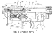
- The gas-driven firing unit a of a regular air-soft gun, as shown in
FIG. 1 , generally comprises abolt body 10, apiston 20, ahammer 30, a gasintake control mechanism 40 and amagazine 50. Thebolt body 10 has anaccommodation chamber 101 at the front side for accommodating thepiston 20, and anopening 102 at the rear side within which thehammer 30 is operable. The gasintake control mechanism 40 is arranged in front of thehammer 30 and behind themagazine 50. Themagazine 50 is disposed beneath thepiston 20, having accommodated therein aseal member 501. Theseal member 501 can be moved forwards to open thegas inlet 201 of thepiston 20 for allowing compressed gas to flow out of themagazine 50 into the inside of thepiston 20 to force thebolt body 10 backwards, thereby producing a backlash. After production of a backlash, theseal member 501 is moved backwards to close thegas inlet 201, thereby stopping the supply of compressed gas. At this time, thebolt body 10 is moved forwards to its former position. - According to the aforesaid structure, the
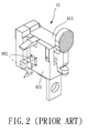
seal member 501 is movable forwards/backwards to open/close thegas inlet 201. As shown inFIGS. 1∼3 , the gasintake control mechanism 40 comprises aholder frame 401, animpact member 402 and a stop block 403 (thestop block 403 is not shown inFIGS. 1 and3 ). Theimpact member 402 is pivotally connected to theholder frame 401, and biasable in and out of theholder frame 401. Thestop block 403 is pivotally connected to the top side of the holder frame 401 (seeFIG. 2 ). - Further, the
magazine 50 has a spring-supportedretaining block 502 disposed at one lateral side relative to theseal member 501. When the spring-supportedretaining block 502 is forced downwards, theseal member 501 can be moved backwards (see FlG. 3). When the toy gun is operated to fire a bullet, theimpact member 402 is driven by thehammer 30 to force theseal member 501 forwards in opening thegas inlet 201 of the piston 20 (see FlG. 1). Thereafter, thebolt body 10 is moved backwards to produce a backlash (see FlG. 3). When thebolt body 10 is moved backwards to a predetermined distance, abottom flange 103 of thebolt body 10 forces the spring-supportedretaining block 502 downwards for allowing theseal member 501 to be returned to close thegas inlet 201 of thepiston 20, and therefore the supply of compressed gas is stopped. - According to the aforesaid prior art design of gas
intake control mechanism 40, the spring-supportedretaining block 502 which controls forward/backward movement of theseal member 501 is mounted in themagazine 50. This arrangement complicates the structural design of themagazine 50 and its fabrication. Further, because the spring-supportedretaining block 502 is located on a place in front of theholder frame 401 and theimpact member 402, the supply of gas is quickly stopped, shortening the backward displacement distance of thebolt body 10, and therefore the backlash thus produced is reduced. - The present invention has been accomplished under the circumstances in view.
- lt is the main object of the present invention to provide a gas intake control mechanism for toy gun, which eliminates the drawbacks of the aforesaid prior art design.
- lt is another object of the present invention to provide a gas intake control mechanism for toy gun, which has a simple structure.
- lt is still another object of the present invention to provide a gas intake control mechanism for toy gun, which utilizes the linking arrangement of a retaining block, a holder frame and an impact member to achieve control of forward and backward movement of a seal member, enhancing the backlash of the toy gun.
- To achieve these and other objects of the present invention, a gas intake control mechanism is installed in a toy gun in front of a hammer and behind a magazine. The toy gun gas intake control mechanism comprises a holder frame, an impact member, a first spring member, a stop block, a retaining block and a second spring member. The holder frame has an opening located on a middle part thereof and an upwardly extending accommodation chamber, an impact member pivotally connected to the holder frame movable forwardly out of the opening by the hammer to strike a seal member in the magazine for causing the seal member to open a gas inlet in a piston inside the toy gun. The impact member comprises an elongated base, a striking block and a pivot axle. The elongated base has a bottom end pivotally connected to the holder and a bumper portion backwardly extended from the top end thereof and strikable by the hammer. The striking block is pivotally connected to the front side of the top end of the elongated base and adapted for striking the seal member. The pivot axle pivotally connects the striking block to the elongated base, having an outer end. The first spring member is mounted between the holder frame and the elongated base of the impact member and adapted to impart a biasing force to the elongated base to hold the impact member in the opening of the holder frame. The stop block is pivotally connected to the top side of the holder frame and biasable upwards to stop the toy gun from firing a toy bullet. The retaining block is received in the accommodation chamber of the holder frame and movable in and out of the accommodation chamber. Further, the retaining block has a retaining notch adapted for receiving the outer end of the pivot axle to hold the impart member in the opening of the holder frame. The second spring member is mounted in the accommodation chamber of the holder frame and adapted to impart an upward pressure to the retaining block for forcing the retaining block partially out of the accommodation chamber when the outer end of the pivot axle is moved out of the retaining notch upon impact between the hammer and the bumper portion of the elongated base of the impact member.
- Further, the retaining block has an oblong coupling hole pivotally connected to the holder frame by a pivot pin for allowing the retaining block to be moved up and down relative to the holder frame within a predetermined distance.
- Further, the retaining block has a recess located on an outside wall thereof above and adjacent to the oblong coupling hole and adapted for stopping the outer end of the pivot axle when the pivot axle is moved out of the retaining notch.
- Further, the holder frame has a transverse through hole transversely extending through the opening. Further, the elongated base of the impact member has a coupling hole transversely located near the bottom end thereof and pivotally connected to the transverse through hole of the holder frame by a pivot shaft.
- The gas intake control mechanism further comprises a third spring member mounted in the elongated base and connected between the elongated base and the striking block, and adapted for imparting a biasing force to the striking block relative to the elongated base.
-
- FlG.1 is a schematic drawing showing a gas intake status of a gas intake control mechanism of a toy gun according to the prior art.
- FlG.2 is a perspective view of the gas intake control mechanism according to the prior art.
- FlG.3 is a schematic drawing showing a gas-off status of the gas intake control mechanism in the toy gun according to the prior art.
- FlG.4 is a schematic drawing sowing the positioning of a gas intake control mechanism in a toy gun according to the present invention.
- FlG.5 is a schematic plain view of the present invention, showing a gas intake status of the gas intake control mechanism.
- FlG.6 is an elevational assembly view of the gas intake control mechanism according to the present invention.
- FlG.7 corresponds to FlG.6 when viewed from another angle.
- FlG.8 is an exploded view of the gas intake control mechanism according to the present invention.
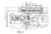
- FlG.9 is a schematic drawing of the present invention a gas-off status of the gas intake control mechanism.
- Referring to FlGS. 4 and 5, a gas intake control mechanism D is shown installed in a toy gun in front of the hammer A behind the magazine B and beneath the bolt body C. The bolt body C accommodates a backwardly extending piston C1 (see FlG.5). The magazine B has a seal member B1 movably disposed at the inner top side thereof. When the seal member B1 is moved forwards, the gas inlet C11 of the piston C1 is opened for enabling a flow of compressed gas to go out of the magazine B into the inside of the piston C1 so that a backlash can be produced upon a backward displacement of the bolt body C (see FlG.9). The gas intake control mechanism D comprises a
holder frame 1, animpact member 2 and a stop block 3 (see FlGS. 6-8). - The
holder frame 1 has anopening 11, an upwardly extendingaccommodation chamber 12 and a transverse throughhole 13 transversely cut through the opening 11 (see FlG.8). The opening 11 is located on the middle of theholder frame 1. Aretaining block 4 is downwardly inserted into the upwardly extendingaccommodation chamber 12 and supported on asecond spring member 52 in the upwardly extendingaccommodation chamber 12. Thecompression spring 52 imparts an upward pressure to theretaining block 4. The retainingblock 4 has a retainingnotch 41, anoblong coupling hole 42 disposed near the bottom end thereof and arecess 411 located on the outside wall above and adjacent to theoblong coupling hole 42. Apivot pin 14 is inserted through the upwardly extendingaccommodation chamber 12 and theoblong coupling hole 42 of the retainingblock 4 to couple the retainingblock 4 to theholder frame 1, along the retainingblock 4 to be moved up and down (in and out of the upwardly extending accommodation chamber 12) within a limited range (subject to the length of the major axis of the oblong coupling hole 42). - The
impact member 2 is received in theopening 11 of theholder frame 1, comprising anelongated base 21 and a striking block 22 (see FlG.8). Theelongated base 21 has acoupling hole 211 transversely cut through the bottom end thereof and pivotally coupled to the transverse throughhole 13 of theholder frame 1 by apivot shaft 23. Further, afirst spring member 51 is mounted around thepivot shaft 23 and stopped with its two opposite ends thereof against theelongated base 21 of theimpact member 2 and a part of theholder frame 1 below the opening 11 (see FlG.6) for reversing theimpact member 2 after theimpact member 2 having been forced forwards. Further, theelongated base 21 has abumper portion 212 backwardly extended from top end thereof. Thestriking block 22 is pivotally connected to the top end of theelongated base 21 in front of thestroke portion 212 by apivot axle 24. Thepivot axle 24 has anouter end 241. Further, athird spring member 53 is mounted around thepivot axle 24 and stopped with its two opposite ends against thestriking block 22 and theelongated base 21. - The stop block 3 (see FlGS. 6∼8) is pivotally mounted on the top side of the
holder frame 1. When no bullet is to be fired, thestop block 3 is lifted. - When the toy gun is operated to fire a bullet, the hammer A is driven forwards (see FlG.5) to strike the
bumper portion 212 of theelongated base 21 of theimpact member 2, forcing thestriking block 22 forwards to strike the seal member B1 of the magazine B. Thus, the seal member B1 is moved forwards to open the gas inlet C11 of the piston C1 for enabling a flow of compressed gas to go out of the magazine B into the inside of the piston C1. Thereafter, the bolt body C is moved backwards to produce a backlash (see FlG.9). During forward displacement of theimpact member 2, theouter end 241 of thepivot axle 24 is moved out of the retainingnotch 41 of the retaining block 4 (see FlG. 5). At this time, the retainingblock 4 is pushed upwards by thesecond spring member 52. After the bolt body C has been moved backwards to a predetermined distance, the retainingblock 4 is forced downwards by abottom flange 12 of the bolt body C (see FlG.9). At this time, theouter end 241 of thepivot axle 24 is engaged into the retainingnotch 41 of the retainingblock 4 again, and theimpact member 2 is returned, and at the same time the seal member B1 is moved backwards to close the gas inlet C11 of the piston C1, thereby stopping the supply of compressed gas. Subject to the linking action of the retainingblock 4, the holder frame and theimpact member 2, the seal member B1 is moved forwards or backwards to control the supply of compressed gas. - As explained above, the linking arrangement of the retaining
block 4, theholder frame 1 and theimpact member 2 simplifies the design of the magazine B. Further, because the bolt body C is moved backwards to force the retainingblock 4 downwards at a late time, the supply of compressed gas is stopped lately, enhancing the backlash and eliminating the drawback of the prior art design. - A prototype of toy gun gas intake control mechanism has been constructed with the features of FlGS. 4∼9. The toy gun gas intake control mechanism functions smoothly to provide all of the features disclosed earlier.
- Although a particular embodiment of the invention has been described in detail for purposes of illustration, various modifications and enhancements may be made without departing from the spirit and scope of the invention. Accordingly, the invention is not to be limited except as by the appended claims.
Claims (5)
- A gas intake control mechanism (D) installed in a toy gun in front of a hammer (A) and behind a magazine (B), the toy gun gas intake control mechanism (D) comprising:a holder frame (1), said holder frame (1) having an opening (11) located on a middle part thereof and an upwardly extending accommodation chamber (12);an impact member (2) pivotally connected to said holder frame (1) and movable forwardly out of said opening (11) by said hammer (A) to strike a seal member (B1) in said magazine (B) for causing said seal member (B1) to open a gas inlet (C11) in a piston (C1) inside said toy gun, said impact member (2) comprising an elongated base (21), a striking block (22) and a pivot axle (24), said elongated base (21) having a bottom end pivotally connected to said holder frame (1) and a bumper portion (212) backwardly extended from a top end thereof and strikable by said hammer (A), said striking block (22) being pivotally connected to a front side of the top end of said elongated base (21) and adapted for striking said seal member (B1), said pivot axle (24) pivotally connecting said striking block (22) to said elongated base (21) and having an outer end (241);a first spring member (51) mounted between said holder frame (1) and said elongated base (21) of said impact member (2) and adapted to impart a biasing force to said elongated base (21) to hold said impact member (2) in said opening (11) of said holder frame (1);a stop block (3) pivotally connected to a top side of said holder frame (1) and biasable upwards to stop said toy gun from firing a toy bullet;a retaining block (4) received in said accommodation chamber (12) of said holder frame (1) and movable in and out of said accommodation chamber (12), said retaining block (4) having a retaining notch (41) adapted for receiving the outer end of said pivot axle (24) to hold said impart member (2) in said opening (11) of said holder frame (1); anda second spring member (52) mounted in said accommodation chamber (12) of said holder frame (1) and adapted to impart an upward pressure to said retaining block (4) for forcing said retaining block (4) partially out of said accommodation chamber (12) when the outer end (241) of said pivot axle (24) is moved out of said retaining notch (41) upon impact between said hammer (A) and said bumper portion (212) of said elongated base (21) of said impact member (2)
- The gas intake control mechanism (D) as claimed in claim 1, wherein said retaining block (4) further has an oblong coupling hole (42) pivotally connected to said holder frame (1) by a pivot pin (14) for allowing said retaining block (4) to be moved up and down relative to said holder frame (1) within a predetermined distance.
- The gas intake control mechanism (D) as claimed in claim 2, wherein said retaining block (4) has a recess (411) located on an outside wall thereof above and adjacent to said oblong coupling hole (42) and adapted for stopping the outer end (241) of said pivot axle (24) when said pivot axle (24) is moved out of said retaining notch (41).
- The gas intake control mechanism (D) as claimed in any of claims 1 to 3, wherein said holder frame (1) has a transverse through hole (13) transversely extending through said opening (11); said elongated base (21) of said impact member (2) has a coupling hole (211) transversely located near the bottom end thereof and pivotally connected to the transverse through hole (13) of said holder frame (1) by a pivot shaft (23).
- The gas intake control mechanism (D) as claimed in claim 4, further comprising a third spring member (53) mounted in said elongated base (21) and connected between said elongated base (21) and said striking block (22) and adapted for imparting a biasing force to said striking block (22) relative to said elongated base (21).
Applications Claiming Priority (1)
| Application Number | Priority Date | Filing Date | Title |
|---|---|---|---|
| TW098220049U TWM389247U (en) | 2009-10-30 | 2009-10-30 | Air-intake control device of toy gun |
Publications (2)
| Publication Number | Publication Date |
|---|---|
| EP2317275A2 true EP2317275A2 (en) | 2011-05-04 |
| EP2317275A3 EP2317275A3 (en) | 2014-04-23 |
Family
ID=43110681
Family Applications (1)
| Application Number | Title | Priority Date | Filing Date |
|---|---|---|---|
| EP10182556.0A Withdrawn EP2317275A3 (en) | 2009-10-30 | 2010-09-29 | Gas intake control mechanism for toy gun |
Country Status (2)
| Country | Link |
|---|---|
| EP (1) | EP2317275A3 (en) |
| TW (1) | TWM389247U (en) |
Cited By (4)
| Publication number | Priority date | Publication date | Assignee | Title |
|---|---|---|---|---|
| FR2975919A1 (en) * | 2011-05-31 | 2012-12-07 | Poh Kae Co Ltd | Back and forth movement apparatus for bolt of toy pistol, has pole comprising extended portion adjacent to rear end before being engaged with slot of base, and torsion spring located between base and pole for stressing pole |
| EP2578984A1 (en) * | 2011-10-07 | 2013-04-10 | Yih Kai Enterprise Co., Ltd | Firing linkage mechanism for toy submachine gun |
| CN103047901A (en) * | 2011-10-11 | 2013-04-17 | 奕凯企业股份有限公司 | Firing linkage unit of toy submachine gun |
| EP2660552A3 (en) * | 2012-05-02 | 2014-12-24 | Planet Eclipse Limited | Paintball marker with release mechanism |
Family Cites Families (5)
| Publication number | Priority date | Publication date | Assignee | Title |
|---|---|---|---|---|
| JPH10220993A (en) * | 1997-01-31 | 1998-08-21 | K S C:Kk | Safety device of toy air gun |
| TW410973U (en) * | 1997-10-16 | 2000-11-01 | Western Arms Kk | Model gun with automatic bullet supplying mechanism |
| JP3711282B2 (en) * | 2003-06-25 | 2005-11-02 | 株式会社ウエスタン・アームス | Gas supply mechanism of gas toy gun |
| TWI261105B (en) * | 2005-12-26 | 2006-09-01 | Yih Kai Entpr Co Ltd | Improved structure of machine set for toy gas gun |
| US20090013578A1 (en) * | 2006-12-29 | 2009-01-15 | Yu-Chyong Wang | Air gun linking mechanism |
-
2009
- 2009-10-30 TW TW098220049U patent/TWM389247U/en not_active IP Right Cessation
-
2010
- 2010-09-29 EP EP10182556.0A patent/EP2317275A3/en not_active Withdrawn
Non-Patent Citations (1)
| Title |
|---|
| None |
Cited By (6)
| Publication number | Priority date | Publication date | Assignee | Title |
|---|---|---|---|---|
| FR2975919A1 (en) * | 2011-05-31 | 2012-12-07 | Poh Kae Co Ltd | Back and forth movement apparatus for bolt of toy pistol, has pole comprising extended portion adjacent to rear end before being engaged with slot of base, and torsion spring located between base and pole for stressing pole |
| EP2578984A1 (en) * | 2011-10-07 | 2013-04-10 | Yih Kai Enterprise Co., Ltd | Firing linkage mechanism for toy submachine gun |
| CN103047901A (en) * | 2011-10-11 | 2013-04-17 | 奕凯企业股份有限公司 | Firing linkage unit of toy submachine gun |
| CN103047901B (en) * | 2011-10-11 | 2014-09-24 | 奕凯企业股份有限公司 | Firing linkage unit of toy submachine gun |
| EP2660552A3 (en) * | 2012-05-02 | 2014-12-24 | Planet Eclipse Limited | Paintball marker with release mechanism |
| US8960175B2 (en) | 2012-05-02 | 2015-02-24 | Planet Eclipse Limited | Paintball marker with advanced gas release mechanism |
Also Published As
| Publication number | Publication date |
|---|---|
| TWM389247U (en) | 2010-09-21 |
| EP2317275A3 (en) | 2014-04-23 |
Similar Documents
| Publication | Publication Date | Title |
|---|---|---|
| US8051847B2 (en) | Gas intake control mechanism for toy gun | |
| US8585407B2 (en) | Toy gun backlash vibration mechanism | |
| US7726293B2 (en) | Continuous firing type trigger structure for toy gun | |
| US7946283B2 (en) | Toy gun mechanism with a sliding bolt assembly | |
| US5509399A (en) | Semi-automatic fluid powered gun | |
| TWI407074B (en) | Electric air gun | |
| US8449346B2 (en) | Backward momentum transferring mechanism for toy gun | |
| US7963281B2 (en) | Electric toy gun and motion control mechanism thereof | |
| EP2503278A2 (en) | Electric toy gun | |
| EP2578984A1 (en) | Firing linkage mechanism for toy submachine gun | |
| EP2317275A2 (en) | Gas intake control mechanism for toy gun | |
| US20110041825A1 (en) | Gun-lock assembly | |
| US8176907B2 (en) | Projectile-loading assembly for air-powered gun | |
| US11609063B1 (en) | Toy gun with pressure diverter | |
| CN112179201B (en) | Be applied to unmanned aerial vehicle's no recoil firearm | |
| EP2275768A2 (en) | Toy gun with recoil mechanism | |
| HK1157439A (en) | Gas intake control mechanism for toy gun | |
| TWI569932B (en) | Pneumatic gun with mechanically actuated pneumatic valve | |
| CN220794014U (en) | Novel gun die for realizing automatic back-firing and emission by taking pre-stored compressed gas as power | |
| KR101567017B1 (en) | Mimetic rifle | |
| US20050066952A1 (en) | Air gun | |
| CN201059909Y (en) | Pneumatic, manual double dynamical type toy gun | |
| EP2392888A1 (en) | Firing actuator mechanism for toy gun | |
| CN117029571B (en) | Novel gun die for realizing automatic back-firing and emission by taking pre-stored compressed gas as power | |
| CN2921768Y (en) | Improved structure of piston cylinder of toy gun |
Legal Events
| Date | Code | Title | Description |
|---|---|---|---|
| PUAI | Public reference made under article 153(3) epc to a published international application that has entered the european phase |
Free format text: ORIGINAL CODE: 0009012 |
|
| AK | Designated contracting states |
Kind code of ref document: A2 Designated state(s): AL AT BE BG CH CY CZ DE DK EE ES FI FR GB GR HR HU IE IS IT LI LT LU LV MC MK MT NL NO PL PT RO SE SI SK SM TR |
|
| AX | Request for extension of the european patent |
Extension state: BA ME RS |
|
| REG | Reference to a national code |
Ref country code: HK Ref legal event code: DE Ref document number: 1157439 Country of ref document: HK |
|
| PUAL | Search report despatched |
Free format text: ORIGINAL CODE: 0009013 |
|
| AK | Designated contracting states |
Kind code of ref document: A3 Designated state(s): AL AT BE BG CH CY CZ DE DK EE ES FI FR GB GR HR HU IE IS IT LI LT LU LV MC MK MT NL NO PL PT RO SE SI SK SM TR |
|
| AX | Request for extension of the european patent |
Extension state: BA ME RS |
|
| STAA | Information on the status of an ep patent application or granted ep patent |
Free format text: STATUS: THE APPLICATION IS DEEMED TO BE WITHDRAWN |
|
| 18D | Application deemed to be withdrawn |
Effective date: 20141024 |
|
| REG | Reference to a national code |
Ref country code: DE Ref legal event code: R079 Free format text: PREVIOUS MAIN CLASS: F41B0011060000 Ipc: F41B0011620000 |
|
| REG | Reference to a national code |
Ref country code: DE Ref legal event code: R079 Free format text: PREVIOUS MAIN CLASS: F41B0011060000 Ipc: F41B0011620000 Effective date: 20150519 |
|
| REG | Reference to a national code |
Ref country code: HK Ref legal event code: WD Ref document number: 1157439 Country of ref document: HK |