EP2319454A1 - Bypass-Vorrichtung zur Beeinflussung des Blutdrucks - Google Patents
Bypass-Vorrichtung zur Beeinflussung des Blutdrucks Download PDFInfo
- Publication number
- EP2319454A1 EP2319454A1 EP10014333A EP10014333A EP2319454A1 EP 2319454 A1 EP2319454 A1 EP 2319454A1 EP 10014333 A EP10014333 A EP 10014333A EP 10014333 A EP10014333 A EP 10014333A EP 2319454 A1 EP2319454 A1 EP 2319454A1
- Authority
- EP
- European Patent Office
- Prior art keywords
- pressure
- volume
- bypass device
- mmhg
- implant
- Prior art date
- Legal status (The legal status is an assumption and is not a legal conclusion. Google has not performed a legal analysis and makes no representation as to the accuracy of the status listed.)
- Granted
Links
- CDTDMKCVKCGRPD-UHFFFAOYSA-N CC(C)C1CC(C)CC1 Chemical compound CC(C)C1CC(C)CC1 CDTDMKCVKCGRPD-UHFFFAOYSA-N 0.000 description 1
Images


Classifications
-
- A—HUMAN NECESSITIES
- A61—MEDICAL OR VETERINARY SCIENCE; HYGIENE
- A61F—FILTERS IMPLANTABLE INTO BLOOD VESSELS; PROSTHESES; DEVICES PROVIDING PATENCY TO, OR PREVENTING COLLAPSING OF, TUBULAR STRUCTURES OF THE BODY, e.g. STENTS; ORTHOPAEDIC, NURSING OR CONTRACEPTIVE DEVICES; FOMENTATION; TREATMENT OR PROTECTION OF EYES OR EARS; BANDAGES, DRESSINGS OR ABSORBENT PADS; FIRST-AID KITS
- A61F2/00—Filters implantable into blood vessels; Prostheses, i.e. artificial substitutes or replacements for parts of the body; Appliances for connecting them with the body; Devices providing patency to, or preventing collapsing of, tubular structures of the body, e.g. stents
- A61F2/02—Prostheses implantable into the body
- A61F2/04—Hollow or tubular parts of organs, e.g. bladders, tracheae, bronchi or bile ducts
- A61F2/06—Blood vessels
-
- A—HUMAN NECESSITIES
- A61—MEDICAL OR VETERINARY SCIENCE; HYGIENE
- A61F—FILTERS IMPLANTABLE INTO BLOOD VESSELS; PROSTHESES; DEVICES PROVIDING PATENCY TO, OR PREVENTING COLLAPSING OF, TUBULAR STRUCTURES OF THE BODY, e.g. STENTS; ORTHOPAEDIC, NURSING OR CONTRACEPTIVE DEVICES; FOMENTATION; TREATMENT OR PROTECTION OF EYES OR EARS; BANDAGES, DRESSINGS OR ABSORBENT PADS; FIRST-AID KITS
- A61F2/00—Filters implantable into blood vessels; Prostheses, i.e. artificial substitutes or replacements for parts of the body; Appliances for connecting them with the body; Devices providing patency to, or preventing collapsing of, tubular structures of the body, e.g. stents
- A61F2/02—Prostheses implantable into the body
- A61F2/04—Hollow or tubular parts of organs, e.g. bladders, tracheae, bronchi or bile ducts
- A61F2/06—Blood vessels
- A61F2/07—Stent-grafts
-
- A—HUMAN NECESSITIES
- A61—MEDICAL OR VETERINARY SCIENCE; HYGIENE
- A61M—DEVICES FOR INTRODUCING MEDIA INTO, OR ONTO, THE BODY; DEVICES FOR TRANSDUCING BODY MEDIA OR FOR TAKING MEDIA FROM THE BODY; DEVICES FOR PRODUCING OR ENDING SLEEP OR STUPOR
- A61M60/00—Blood pumps; Devices for mechanical circulatory actuation; Balloon pumps for circulatory assistance
- A61M60/10—Location thereof with respect to the patient's body
- A61M60/122—Implantable pumps or pumping devices, i.e. the blood being pumped inside the patient's body
- A61M60/126—Implantable pumps or pumping devices, i.e. the blood being pumped inside the patient's body implantable via, into, inside, in line, branching on, or around a blood vessel
- A61M60/152—Implantable pumps or pumping devices, i.e. the blood being pumped inside the patient's body implantable via, into, inside, in line, branching on, or around a blood vessel branching on and drawing blood from a blood vessel
-
- A—HUMAN NECESSITIES
- A61—MEDICAL OR VETERINARY SCIENCE; HYGIENE
- A61M—DEVICES FOR INTRODUCING MEDIA INTO, OR ONTO, THE BODY; DEVICES FOR TRANSDUCING BODY MEDIA OR FOR TAKING MEDIA FROM THE BODY; DEVICES FOR PRODUCING OR ENDING SLEEP OR STUPOR
- A61M60/00—Blood pumps; Devices for mechanical circulatory actuation; Balloon pumps for circulatory assistance
- A61M60/20—Type thereof
- A61M60/247—Positive displacement blood pumps
- A61M60/253—Positive displacement blood pumps including a displacement member directly acting on the blood
- A61M60/268—Positive displacement blood pumps including a displacement member directly acting on the blood the displacement member being flexible, e.g. membranes, diaphragms or bladders
-
- A—HUMAN NECESSITIES
- A61—MEDICAL OR VETERINARY SCIENCE; HYGIENE
- A61M—DEVICES FOR INTRODUCING MEDIA INTO, OR ONTO, THE BODY; DEVICES FOR TRANSDUCING BODY MEDIA OR FOR TAKING MEDIA FROM THE BODY; DEVICES FOR PRODUCING OR ENDING SLEEP OR STUPOR
- A61M60/00—Blood pumps; Devices for mechanical circulatory actuation; Balloon pumps for circulatory assistance
- A61M60/40—Details relating to driving
- A61M60/424—Details relating to driving for positive displacement blood pumps
- A61M60/427—Details relating to driving for positive displacement blood pumps the force acting on the blood contacting member being hydraulic or pneumatic
-
- A—HUMAN NECESSITIES
- A61—MEDICAL OR VETERINARY SCIENCE; HYGIENE
- A61M—DEVICES FOR INTRODUCING MEDIA INTO, OR ONTO, THE BODY; DEVICES FOR TRANSDUCING BODY MEDIA OR FOR TAKING MEDIA FROM THE BODY; DEVICES FOR PRODUCING OR ENDING SLEEP OR STUPOR
- A61M60/00—Blood pumps; Devices for mechanical circulatory actuation; Balloon pumps for circulatory assistance
- A61M60/50—Details relating to control
- A61M60/508—Electronic control means, e.g. for feedback regulation
- A61M60/515—Regulation using real-time patient data
- A61M60/531—Regulation using real-time patient data using blood pressure data, e.g. from blood pressure sensors
-
- A—HUMAN NECESSITIES
- A61—MEDICAL OR VETERINARY SCIENCE; HYGIENE
- A61M—DEVICES FOR INTRODUCING MEDIA INTO, OR ONTO, THE BODY; DEVICES FOR TRANSDUCING BODY MEDIA OR FOR TAKING MEDIA FROM THE BODY; DEVICES FOR PRODUCING OR ENDING SLEEP OR STUPOR
- A61M60/00—Blood pumps; Devices for mechanical circulatory actuation; Balloon pumps for circulatory assistance
- A61M60/80—Constructional details other than related to driving
- A61M60/835—Constructional details other than related to driving of positive displacement blood pumps
- A61M60/837—Aspects of flexible displacement members, e.g. shapes or materials
-
- A—HUMAN NECESSITIES
- A61—MEDICAL OR VETERINARY SCIENCE; HYGIENE
- A61M—DEVICES FOR INTRODUCING MEDIA INTO, OR ONTO, THE BODY; DEVICES FOR TRANSDUCING BODY MEDIA OR FOR TAKING MEDIA FROM THE BODY; DEVICES FOR PRODUCING OR ENDING SLEEP OR STUPOR
- A61M60/00—Blood pumps; Devices for mechanical circulatory actuation; Balloon pumps for circulatory assistance
- A61M60/80—Constructional details other than related to driving
- A61M60/855—Constructional details other than related to driving of implantable pumps or pumping devices
- A61M60/871—Energy supply devices; Converters therefor
- A61M60/882—Devices powered by the patient, e.g. skeletal muscle powered devices
-
- A—HUMAN NECESSITIES
- A61—MEDICAL OR VETERINARY SCIENCE; HYGIENE
- A61F—FILTERS IMPLANTABLE INTO BLOOD VESSELS; PROSTHESES; DEVICES PROVIDING PATENCY TO, OR PREVENTING COLLAPSING OF, TUBULAR STRUCTURES OF THE BODY, e.g. STENTS; ORTHOPAEDIC, NURSING OR CONTRACEPTIVE DEVICES; FOMENTATION; TREATMENT OR PROTECTION OF EYES OR EARS; BANDAGES, DRESSINGS OR ABSORBENT PADS; FIRST-AID KITS
- A61F2/00—Filters implantable into blood vessels; Prostheses, i.e. artificial substitutes or replacements for parts of the body; Appliances for connecting them with the body; Devices providing patency to, or preventing collapsing of, tubular structures of the body, e.g. stents
- A61F2/02—Prostheses implantable into the body
- A61F2/04—Hollow or tubular parts of organs, e.g. bladders, tracheae, bronchi or bile ducts
- A61F2/06—Blood vessels
- A61F2002/068—Modifying the blood flow model, e.g. by diffuser or deflector
-
- A—HUMAN NECESSITIES
- A61—MEDICAL OR VETERINARY SCIENCE; HYGIENE
- A61F—FILTERS IMPLANTABLE INTO BLOOD VESSELS; PROSTHESES; DEVICES PROVIDING PATENCY TO, OR PREVENTING COLLAPSING OF, TUBULAR STRUCTURES OF THE BODY, e.g. STENTS; ORTHOPAEDIC, NURSING OR CONTRACEPTIVE DEVICES; FOMENTATION; TREATMENT OR PROTECTION OF EYES OR EARS; BANDAGES, DRESSINGS OR ABSORBENT PADS; FIRST-AID KITS
- A61F2/00—Filters implantable into blood vessels; Prostheses, i.e. artificial substitutes or replacements for parts of the body; Appliances for connecting them with the body; Devices providing patency to, or preventing collapsing of, tubular structures of the body, e.g. stents
- A61F2/02—Prostheses implantable into the body
- A61F2/30—Joints
- A61F2002/30001—Additional features of subject-matter classified in A61F2/28, A61F2/30 and subgroups thereof
- A61F2002/30003—Material related properties of the prosthesis or of a coating on the prosthesis
- A61F2002/3006—Properties of materials and coating materials
- A61F2002/30069—Properties of materials and coating materials elastomeric
-
- A—HUMAN NECESSITIES
- A61—MEDICAL OR VETERINARY SCIENCE; HYGIENE
- A61F—FILTERS IMPLANTABLE INTO BLOOD VESSELS; PROSTHESES; DEVICES PROVIDING PATENCY TO, OR PREVENTING COLLAPSING OF, TUBULAR STRUCTURES OF THE BODY, e.g. STENTS; ORTHOPAEDIC, NURSING OR CONTRACEPTIVE DEVICES; FOMENTATION; TREATMENT OR PROTECTION OF EYES OR EARS; BANDAGES, DRESSINGS OR ABSORBENT PADS; FIRST-AID KITS
- A61F2/00—Filters implantable into blood vessels; Prostheses, i.e. artificial substitutes or replacements for parts of the body; Appliances for connecting them with the body; Devices providing patency to, or preventing collapsing of, tubular structures of the body, e.g. stents
- A61F2/02—Prostheses implantable into the body
- A61F2/30—Joints
- A61F2002/30001—Additional features of subject-matter classified in A61F2/28, A61F2/30 and subgroups thereof
- A61F2002/30003—Material related properties of the prosthesis or of a coating on the prosthesis
- A61F2002/3006—Properties of materials and coating materials
- A61F2002/30074—Properties of materials and coating materials stretchable
-
- A—HUMAN NECESSITIES
- A61—MEDICAL OR VETERINARY SCIENCE; HYGIENE
- A61F—FILTERS IMPLANTABLE INTO BLOOD VESSELS; PROSTHESES; DEVICES PROVIDING PATENCY TO, OR PREVENTING COLLAPSING OF, TUBULAR STRUCTURES OF THE BODY, e.g. STENTS; ORTHOPAEDIC, NURSING OR CONTRACEPTIVE DEVICES; FOMENTATION; TREATMENT OR PROTECTION OF EYES OR EARS; BANDAGES, DRESSINGS OR ABSORBENT PADS; FIRST-AID KITS
- A61F2/00—Filters implantable into blood vessels; Prostheses, i.e. artificial substitutes or replacements for parts of the body; Appliances for connecting them with the body; Devices providing patency to, or preventing collapsing of, tubular structures of the body, e.g. stents
- A61F2/02—Prostheses implantable into the body
- A61F2/30—Joints
- A61F2002/30001—Additional features of subject-matter classified in A61F2/28, A61F2/30 and subgroups thereof
- A61F2002/30316—The prosthesis having different structural features at different locations within the same prosthesis; Connections between prosthetic parts; Special structural features of bone or joint prostheses not otherwise provided for
- A61F2002/30535—Special structural features of bone or joint prostheses not otherwise provided for
- A61F2002/30537—Special structural features of bone or joint prostheses not otherwise provided for adjustable
- A61F2002/30548—Special structural features of bone or joint prostheses not otherwise provided for adjustable for adjusting fluid pressure
-
- A—HUMAN NECESSITIES
- A61—MEDICAL OR VETERINARY SCIENCE; HYGIENE
- A61F—FILTERS IMPLANTABLE INTO BLOOD VESSELS; PROSTHESES; DEVICES PROVIDING PATENCY TO, OR PREVENTING COLLAPSING OF, TUBULAR STRUCTURES OF THE BODY, e.g. STENTS; ORTHOPAEDIC, NURSING OR CONTRACEPTIVE DEVICES; FOMENTATION; TREATMENT OR PROTECTION OF EYES OR EARS; BANDAGES, DRESSINGS OR ABSORBENT PADS; FIRST-AID KITS
- A61F2210/00—Particular material properties of prostheses classified in groups A61F2/00 - A61F2/26 or A61F2/82 or A61F9/00 or A61F11/00 or subgroups thereof
- A61F2210/0057—Particular material properties of prostheses classified in groups A61F2/00 - A61F2/26 or A61F2/82 or A61F9/00 or A61F11/00 or subgroups thereof stretchable
-
- A—HUMAN NECESSITIES
- A61—MEDICAL OR VETERINARY SCIENCE; HYGIENE
- A61F—FILTERS IMPLANTABLE INTO BLOOD VESSELS; PROSTHESES; DEVICES PROVIDING PATENCY TO, OR PREVENTING COLLAPSING OF, TUBULAR STRUCTURES OF THE BODY, e.g. STENTS; ORTHOPAEDIC, NURSING OR CONTRACEPTIVE DEVICES; FOMENTATION; TREATMENT OR PROTECTION OF EYES OR EARS; BANDAGES, DRESSINGS OR ABSORBENT PADS; FIRST-AID KITS
- A61F2250/00—Special features of prostheses classified in groups A61F2/00 - A61F2/26 or A61F2/82 or A61F9/00 or A61F11/00 or subgroups thereof
- A61F2250/0001—Means for transferring electromagnetic energy to implants
- A61F2250/0002—Means for transferring electromagnetic energy to implants for data transfer
-
- A—HUMAN NECESSITIES
- A61—MEDICAL OR VETERINARY SCIENCE; HYGIENE
- A61F—FILTERS IMPLANTABLE INTO BLOOD VESSELS; PROSTHESES; DEVICES PROVIDING PATENCY TO, OR PREVENTING COLLAPSING OF, TUBULAR STRUCTURES OF THE BODY, e.g. STENTS; ORTHOPAEDIC, NURSING OR CONTRACEPTIVE DEVICES; FOMENTATION; TREATMENT OR PROTECTION OF EYES OR EARS; BANDAGES, DRESSINGS OR ABSORBENT PADS; FIRST-AID KITS
- A61F2250/00—Special features of prostheses classified in groups A61F2/00 - A61F2/26 or A61F2/82 or A61F9/00 or A61F11/00 or subgroups thereof
- A61F2250/0004—Special features of prostheses classified in groups A61F2/00 - A61F2/26 or A61F2/82 or A61F9/00 or A61F11/00 or subgroups thereof adjustable
- A61F2250/0013—Special features of prostheses classified in groups A61F2/00 - A61F2/26 or A61F2/82 or A61F9/00 or A61F11/00 or subgroups thereof adjustable for adjusting fluid pressure
-
- A—HUMAN NECESSITIES
- A61—MEDICAL OR VETERINARY SCIENCE; HYGIENE
- A61M—DEVICES FOR INTRODUCING MEDIA INTO, OR ONTO, THE BODY; DEVICES FOR TRANSDUCING BODY MEDIA OR FOR TAKING MEDIA FROM THE BODY; DEVICES FOR PRODUCING OR ENDING SLEEP OR STUPOR
- A61M60/00—Blood pumps; Devices for mechanical circulatory actuation; Balloon pumps for circulatory assistance
- A61M60/10—Location thereof with respect to the patient's body
- A61M60/122—Implantable pumps or pumping devices, i.e. the blood being pumped inside the patient's body
- A61M60/126—Implantable pumps or pumping devices, i.e. the blood being pumped inside the patient's body implantable via, into, inside, in line, branching on, or around a blood vessel
- A61M60/148—Implantable pumps or pumping devices, i.e. the blood being pumped inside the patient's body implantable via, into, inside, in line, branching on, or around a blood vessel in line with a blood vessel using resection or like techniques, e.g. permanent endovascular heart assist devices
Definitions
- the Windkessel function causes a homogenization of the arterial blood flow in the circulatory periphery.
- a diminished or Disturbed air vessel function of natural arteries means a fundamentally higher work for the heart, whereby the risk of heart damage increases in the long term.
- Due to the elastic inner wall of the vascular prosthesis DE 10 2004 018 255 A1 By stretching the inner wall during systole (ejection phase of the heart), a larger amount of blood is briefly stored. During diastole (relaxation of the heart muscle), the temporary vascular prosthesis stored blood is pushed out of the vascular prosthesis due to the elasticity of the inner wall.
- the pressure threshold is adjustable.
- the pressure threshold is from the outside adjustable.
- the pressure threshold value could be set by way of suitable control of the implant from the outside in such a way that certain blood pressures of the patient are not exceeded. This allows the pressure threshold to be set individually for each patient. It is also conceivable that the pressure threshold value is set as a function of the expected load on the cardiovascular system. For example, compared to a very moderate load, another pressure threshold can be set for expected high loads.
- FIGS. 3 to 5 Further embodiments of the implant according to the invention are shown, wherein parts or features corresponding to the parts or features of FIG. 1 are similar or identical, be provided with the same reference numerals.
Landscapes
- Health & Medical Sciences (AREA)
- Engineering & Computer Science (AREA)
- Heart & Thoracic Surgery (AREA)
- General Health & Medical Sciences (AREA)
- Public Health (AREA)
- Cardiology (AREA)
- Biomedical Technology (AREA)
- Life Sciences & Earth Sciences (AREA)
- Animal Behavior & Ethology (AREA)
- Veterinary Medicine (AREA)
- Hematology (AREA)
- Anesthesiology (AREA)
- Mechanical Engineering (AREA)
- Vascular Medicine (AREA)
- Gastroenterology & Hepatology (AREA)
- Oral & Maxillofacial Surgery (AREA)
- Pulmonology (AREA)
- Transplantation (AREA)
- Medical Informatics (AREA)
- Rheumatology (AREA)
- Prostheses (AREA)
- External Artificial Organs (AREA)
- Measuring Pulse, Heart Rate, Blood Pressure Or Blood Flow (AREA)
- Surgical Instruments (AREA)
Abstract
Description
- Die Erfindung betrifft eine Bypass-Vorrichtung zur Beeinflussung des Blutdrucks, die ein Implantat mit einer Volumenkammer umfasst. Das Implantat weist Verbindungsmittel zum Verbinden der Volumenkammer an ein natürliches kardiovaskuläres System und Anpassungsmittel auf, durch die eine Volumenänderung eines Volumens der Volumenkammer bei einer Druckänderung in dem kardiovaskulären oder in der Volumenkammer ermöglicht oder bewirkt wird.
- Die
DE 10 2004 018 255 A1 offenbart ein Implantat in Form einer Gefäßprothese, die im Wesentlichen als Rohr mit einer elastischen Innenwandung ausgebildet ist. Durch eine Vliesstruktur wird die Dehnbarkeit der elastischen Innenwandung begrenzt, wodurch ein Druck-Dehnungsverhalten erreicht wird, das im Wesentlichen der Dehnbarkeit von natürlichen Arterien bei systolischem Druck und diastolischem Druck entspricht. Somit kann die Gefäßprothese den sogenannten Windkesseleffekt der natürlichen Arterien und insbesondere der Aorta wiederherstellen oder unterstützen. Unter der Windkesselfunktion versteht man das Zurückhalten eines Teils des vom Herzen ausgeworfenen Blutvolumens während der Systole in den elastischen zentralen Arterien und dessen kontinuierliche Abgabe während der Diastole. Die Windkesselfunktion bewirkt eine Vergleichmäßigung des arteriellen Blutflusses in der Kreislaufperipherie. Eine verminderte oder gestörte Windkesselfunktion von natürlichen Arterien bedeutet für das Herz eine grundsätzlich höhere Arbeit, wobei langfristig die Gefahr von Herzschädigungen ansteigt. Durch die elastische Innenwandung der Gefäßprothese derDE 10 2004 018 255 A1 wird durch Dehnung der Innenwandung während der Systole (Auswurfphase des Herzens) kurzzeitig eine größere Blutmenge gespeichert. Während der Diastole (Entspannung des Herzmuskels) wird das kurzzeitig gefäßprothesegespeicherte Blut aufgrund der Elastizität der Innenwandung wieder aus der Gefäßprothese herausgedrückt. - Auch aus der
DE 10 2005 058 409 A1 ist ein Implantat als Ersatz eines Abschnitts der Aorta oder einer Arterie bekannt, dessen Volumen durch ein in die Gefäßwandung eingearbeitetes Federmittel elastisch verformbar ausgebildet ist. Auch dieses Implantat stützt den Windkesseleffekt. - Es sei auch auf die
US 6,450,942 B1 verwiesen, die ebenfalls ein Implantat offenbart, um die Nachgiebigkeit des natürlichen arteriellen Systems wieder zu gewinnen oder zu vergrößern, um den arteriellen Blutstrom zu verbessern. Es soll dadurch die Belastung des Herzmuskels vermindert werden, da dieser wirksamer seine Arbeit verrichten kann. - Gleichwohl durch die bekannten Vorrichtungen aus dem Stand der Technik der natürliche Windkesseleffekt nachgebildet oder unterstützt wird und somit eine blutdrucksenkende Wirkung erzielt wird, lassen sich diese Vorrichtungen nur sehr begrenzt zur Therapie von Bluthochdruck einsetzen. Eine zusätzliche Medikamenteneinnahme durch den Patienten scheint dabei weiterhin erforderlich zu sein. Die Einnahme der Medikamente kann von teilweisen erheblichen oder schädigenden Nebenwirkungen begleitet sein, so dass stets eine Abwegung zwischen der notwendigen Blutdruckregulierung und dem Einfluss auf das Wohlbefinden des Patienten erfolgen muss. Auch ist der Erfolg dieser Therapieform weitgehend abhängig von der Mitwirkung des Patienten bei der Medikamenteneinnahme.
- Der Erfindung liegt daher die Aufgabe zugrunde, eine Vorrichtung zur Beeinflussung des Blutdrucks bereitzustellen, durch die insbesondere Bluthochdruck effektiv und möglichst ohne die Notwendigkeit der Einnahme von Medikamenten therapiert werden kann.
- Die der Erfindung zugrunde liegende Aufgabe wird mit der Merkmalskombination gemäß Anspruch 1 gelöst. Bevorzugte Ausführungsbeispiele können den Unteransprüchen entnommen werden.
- Die Vorrichtung zur Beeinflussung des Blutdrucks gemäß Anspruch 1, insbesondere eine Bypass-Vorrichtung, zeichnet sich dadurch aus, dass eine Volumenänderung eines Volumens der Volumenkammer in einem unteren Druckbereich zwischen 50 mmHg und einen mindestens 100 mmHg betragenden Druckschwellenwert höchstens 10 cm3 und in einem oberen Druckbereich zwischen dem Druckschwellenwert und 150 mmHg mindestens 10 cm3 beträgt. Die Volumenänderung im unteren Druckbereich ist so zu verstehen, dass bei einem Druckanstieg von 50 mmHg auf den Druckschwellenwert von 100 mmHg das Volumen der Volumenkammer um höchstens 10 cm3 zunimmt. Entsprechend soll das Volumen der Volumenkammer im oberen Druckbereich bei einem Druckanstieg von 100 mmHg auf 150 mmHg mindestens um 10 cm3 zunehmen.
- Dieser Sachverhalt kann vorzugsweise anhand des Verhältnisses von differentieller Volumenänderung zu differentieller Druckänderung, welches der Steigung einer Kurve in einem V-p-Diagramm entspricht, weiter konkretisiert werden. So kann die differentielle Volumenänderung pro differentieller Druckänderung für Druckwerte in einem unteren Druckbereich zwischen 50 mmHg und einem mindestens 100 mmHg betragenden Druckschwellenwert höchstens 0,2 cm3/mmHg und in einem oberen Druckbereich zwischen dem Druckschwellenwert und 150 mmHg mindestens 0,2 cm3/mmHg betragen.
- Zudem wird, unabhängig von Anspruch 1, hiermit eine Bypass-Vorrichtung zur Beeinflussung des Blutdrucks offenbart, umfassend ein Implantat mit einer Volumenkammer, mit Verbindungsmitteln zum Verbinden der Volumenkammer an ein natürliches kardiovaskuläres System und mit Anpassungsmitteln, durch die eine Volumenänderung eines Volumens der Volumenkammer bei einer Druckänderung in dem kardiovaskulären System oder in der Volumenkammer ermöglicht oder bewirkt wird, wobei die differentielle Volumenänderung pro differentieller Druckänderung für Druckwerte in einem unteren Druckbereich zwischen 50 mmHg und einem mindestens 100 mmHg betragenden Druckschwellenwert höchstens 0,2 cm3/mmHg und in einem oberen Druckbereich zwischen dem Druckschwellenwert und 150 mmHg mindestens 0,2 cm3/mmHg beträgt.
- In einem bevorzugten Ausführungsbeispiel beträgt der Druckschwellenwert mindestens 120 mmHg. Ebenfalls gute Werte bei der Therapie von Bluthochdruck lassen sich erzielen, wenn der Druckschwellenwert über 130 mmHg oder gar 140 mmHg liegt.
- Für die arterielle Druckmessung ermittelt man üblicherweise zwei Werte: den oberen oder ersten Wert nennt man systolischen arteriellen Druck. Er charakterisiert den Druck im Herzen in dem Moment, in dem sich der Herzmuskel maximal zusammenzieht. Sobald sich der Herzmuskel entspannt, sinkt der arterielle Druck auf den zweiten oder unteren Druck ab (diastolischer arterieller Druck). Ein arterieller Bluthochdruck liegt vor, wenn bei wiederholter Messung ein Wert von 140 mmHg für den ersten Wert und 90 mmHg für den zweiten Wert erreicht werden.
- Durch die erfindungsgemäße Bypass-Vorrichtung mit dem Implantat, die eine Volumenkammer aufweist, deren Volumen sich in dem Druckbereich unterhalb des Druckschwellenwertes (unterer Druckbereich) nur sehr wenig ändert, jedoch im Druckbereich oberhalb des Druckschwellenwertes (oberer Druckbereich) sich stark ändern kann, kann gezielt ein arterieller Bluthochdruck therapiert werden.
- Die erfindungsgemäße Bypass-Vorrichtung, die vorzugsweise parallel zu einem Abschnitt eines natürlichen Blutgefäßes implantiert wird, dient dabei der künstlichen Vergrößerung des Volumens des natürlichen kardiovaskulären Systems und bildet auf diese Weise einen in der Größe veränderbaren Volumenpuffer, der insbesondere bei hohen Drücken in dem System kurzzeitig eine gewisse Blutmenge aufnehmen und diese bei nachlassendem Systemdruck wieder abgeben kann.
- Da im unteren Druckbereich sich nur geringe Volumenänderungen der Volumenkammer ergeben, ist auch ein möglicher Einfluss des Implantats auf den Windkesseleffekt im unteren Druckbereich gering. Im oberen Druckbereich hingegen werden große Volumenänderungen zugelassen, die über die Volumenänderungen hinausgehen können, die sich durch den natürlichen Windkesseleffekt bei diesen Druckverhältnissen einstellen würden. Im oberen Druckbereich können aufgrund der vergleichsweise großen Volumenänderungen auftretende Drücke effektiv und gezielt reduziert werden. Der Druckschwellenwert kann dabei, wie oben bereits ausgeführt, unterhalb dem systolischen arteriellen Druck von 140 mmHg liegen, bei dem man bei wiederholter Messung von einer arteriellen Hypertonie ausgeht.
- Die Volumenänderung in dem unteren Druckbereich zwischen 50 mmHg und dem Druckschwellenwert kann auf höchstens 5 cm3 begrenzt sein. Ein noch strengerer Höchstwert liegt bei 3 cm3, so dass im unteren Druckbereich quasi keine Volumenänderung in der Volumenkammer des Implantats stattfindet.
- Im oberen Druckbereich hingegen zwischen dem Druckschwellenwert und 150 mmHg kann die Volumenänderung deutlich höher als 10 cm3 betragen. Beispielsweise können mindestens 15 cm3 als untere Grenze für die Volumenänderung im oberen Druckbereich angesetzt werden. Bevorzugt liegt der untere Grenzwert bei 20 cm3 oder gar 25 cm3.
- Das Verhältnis aus differentieller Volumenänderung zu differentieller Druckänderung kann für Druckwerte im unteren Druckbereich zwischen 50 mmHg und dem Druckschwellenwert höchstens 0,1 cm3/mmHg oder sogar höchstens 0,06 cm3/mmHg betragen. Im oberen Druckbereich zwischen dem Druckschwellenwert und 150 mmHg kann die differentielle Volumenänderung pro differentieller Druckänderung mindestens 0,3 cm3/mmHg, mindestens 0,4 cm3/mmHg oder sogar mindestens 0,5 cm3/mmHg betragen.
- Die Anpassungsmittel, durch die eine Volumenänderung des Volumens der Volumenkammer bei Druckänderung in dem kardiovaskulären System oder in der Volumenkammer ermöglicht oder bewirkt wird, können einen Energiespeicher aufweisen, der bei einem Druckanstieg Energie aufnimmt und bei einem Druckabfall Energie abgibt. Wird beispielsweise bei der Systole ein Druck von 140 mmHg erreicht, nehmen die Anpassungsmittel Energie auf, wodurch ein ansonsten höherer Druckanstieg vermieden wird. In der Diastole ist ein Druckabfall zu beobachten, wobei der Energiespeicher nun seine Energie abgibt und Blut aus der Volumenkammer drückt, wodurch der Druckabfall weniger stark ausfällt.
- Der Energiespeicher kann ein elastisches Material aufweisen, das bevorzugt zumindest teilweise die Volumenkammer begrenzt. Bei Druckanstieg weitet sich dieses elastische Material auf, um dann bei einem Druckabfall wieder in Richtung seiner ursprünglichen Form zu relaxieren. Der Energiespeicher kann alternativ oder zusätzlich Federvorrichtungen umfassen, die der Volumenkammer eine bestimmte geometrische Form aufdrängen, welche sich bei einer Druckänderung ändert. Beispielsweise könnte das Implantat die Form eines Zylinders aufweisen, wobei die Federvorrichtungen den zylindrischen Querschnitt zu einem elliptischen Querschnitt zusammendrücken mit der Folge, dass das Volumen entsprechend reduziert wird. Bei einem Druckanstieg in dem Implantat wird gegen die Kraft der Federvorrichtungen wieder ein nahezu zylindrischer Querschnitt erreicht, wodurch sich das Volumen des Implantats entsprechend vergrößert. Bei Druckabfall wiederum drücken die Federvorrichtungen das Implantat wieder in die Form mit elliptischem Querschnitt. Das Volumen wird wieder reduziert.
- Die Anpassungsmittel können mechanische und/oder elektrische Komponenten umfassen. Auch ist es denkbar, dass die Anpassungsmittel Magnete umfassen, durch die eine Volumenänderung der Volumenkammer gezielt beeinflusst werden kann.
- In einem bevorzugten Ausführungsbeispiel ist der Druckschwellenwert einstellbar. Vorzugsweise ist dabei der Druckschwellenwert von außen einstellbar. So könnte beispielsweise über eine geeignete Ansteuerung des Implantats von außen der Druckschwellenwert so eingestellt werden, dass gewisse Blutdrücke des Patienten nicht überschritten werden. So lässt sich der Druckschwellenwert individuell für jeden Patienten einstellen. Auch ist es denkbar, dass der Druckschwellenwert in Abhängigkeit der zu erwarteten Belastung an das Herzkreislaufsystem eingestellt wird. So kann beispielsweise gegenüber einer sehr moderaten Belastung ein anderer Druckschwellenwert für zu erwartende hohe Belastungen eingestellt werden.
- Der Begriff "von außen einstellbar" bedeutet somit, dass der Druckschwellenwert verändert werden kann, auch wenn das Implantat bereits implantiert ist. Es ist jedoch auch möglich, dass vor der Implantation über entsprechende Einstellungen direkt am Implantat der Druckschwellenwert eingestellt werden kann. Somit ließe sich ein Implantat herstellen, das dann für verschiedene Patienten und Bedürfnisse individuell vor der Implantation eingestellt werden kann.
- Vorzugsweise weist das Implantat eine Steuerung mit einem Sensor auf, durch den ein Druck im kardiovaskulären System oder in der Volumenkammer erfasst werden kann. Bevorzugt kann dabei die Steuerung ein Signal bei Erreichen des Druckschwellenwertes oder eines mit dem Druckschwellenwert korrelierenden Wertes abgeben, welches an die Anpassungsmittel abgegeben werden kann. Liegt beispielsweise der durch den Sensor erfasste Druck unterhalb des Druckschwellenwertes, zeigen die Anpassungsmittel hinsichtlich der Volumenänderung ein anderes Verhalten als in dem Fall auf, in dem der erfasste Druck oberhalb des Druckschwellenwertes liegt.
- Vorzugsweise ist ein äußerer Schutz gegen ein Einwachsen und/oder ein Einwachsen von natürlichem Gewebe an die Volumenkammer vorgesehen. Dadurch kann sichergestellt werden, dass die Volumenkammer und auch die Anpassungsmittel vor natürlichem Gewebe geschützt sind bzw. durch dieses nicht in ihren Funktionen beeinträchtigt wird.
- Ist der Druckschwellenwert von außen einstellbar, bedarf es dafür geeignete Mittel. Diese Mittel können einen Empfänger umfassen, der berührungslos Signale eines von außen sendenden Senders empfängt. Zu dem kann die Vorrichtung auch einen Sender umfassen, um beispielsweise gemessene Werte hinsichtlich Blutdruck, Pulsfrequenz etc. auslesen zu können. Der Austausch bzw. das Senden oder Empfangen kann mit Hilfe von elektromagnetischen Wellen geschehen, zum Beispiel durch Radio Frequency Identification (RFID).
- Zur Beeinflussung des venösen Blutdrucks - zusätzlich zur Beeinflussung des arteriellen Blutdrucks - kann ein Reservoir vorgesehen sein, das eine Kapazität von 100 ml bis 1000 ml, vorzugsweise 500 ml bis 750 ml aufweist. Das Reservoir kann dabei schneckenförmig und/oder spiralförmig sein. In einem bevorzugten Ausführungsbeispiel kann das durch das Reservoir aufnehmbare Blutvolumen vorbestimmbar und kalibrierbar sein, um eine Sollmenge des venösen Blutvolumens für jeden Patienten individuell einzustellen. Diese Einstellung des aufnehmbaren Blutvolumens kann von außen und möglicherweise auf ärztliche Anweisung regulierbar sein.
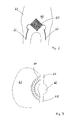
- Anhand der in den Zeichnungen dargestellten Ausführungsbeispiele wird die Erfindung näher erläutert. Es zeigen:
- Fig. 1
- Ein erstes Ausführungsbeispiel für ein erfindungsgemäßen Implantat;
- Fig. 2
- Ein Verlauf eines Blutdrucks über einer Volumenänderung;
- Fig. 3
- Ein zweites Ausführungsbeispiel des erfindungsgemäßen Implantats und einen Aortabogen;
- Fig. 4
- Ein drittes Ausführungsbeispiel des erfindungsgemäßen Implantats;
- Fig. 5
- Weitere Ausführungsbeispiele des erfindungsgemäßen Implantats;
- Fig. 6
- Ein erstes Ausführungsbeispiel für ein venöses Reservoir; und
- Fig. 7
- Ein zweites Ausführungsbeispiel für das venöse Reservoir.
-
Figur 1 zeigt ein erstes Ausführungsbeispiel für ein erfindungsgemäßes Implantat, das in seiner Gesamtheit mit 10 bezeichnet wird. Das Implantat 10 umfasst ein biokompatibles elastisches Rohr 11, an dessen Enden zwei Ringe 12a, 12b befestigt sind. Die Ringe 12a, 12b dienen als Vernähungsringe, um eine Befestigung des Implantats 10 in oder an einem kardiovaskulären System zu ermöglichen. Das Implantat 10 weist zudem eine biokompatible äußere Hülle 13 auf, die verhindern soll, dass natürliches Gewebe die Funktion des elastischen Rohres oder Schlauches 11 beeinträchtigt. - Aufgrund der Elastizität des Rohres 11 weitet sich dieses aus, wenn das Implantat mit einem Druck beaufschlagt wird. Die Linien 14a, 14b und 14c sollen unterschiedliche Verformzustände des Rohres 11 darstellen, wenn in dem Rohr ein Druck herrscht, der die Rohrwandung nach außen drückt. Beim Verformungszustand 14c liegt dabei der höchste Druck an, während beim Verformungszustand 14a der kleinste Druck gegeben ist. Der Druck beim Verformungszustand 14b liegt zwischen den Drücken der Verformungszustände 14a, 14c.
- Durch das verformte Rohr 11 ändert sich auch ein Volumen V einer Volumenkammer 15, die durch die Rohrwandung des Rohres 11 begrenzt wird. Im Verformzustand 14c ergibt sich somit das größte Volumen Vc der Volumenkammer 15 des Implantats 10.
-
Figur 2 zeigt den Zusammenhang zwischen einem Blutdruck P in der Volumenkammer 15 und einer Volumenänderung ΔV des Volumens der Volumenkammer 15. Durch einen Druckschwellenwert Ps werden ein unterer Druckbereich und ein oberer Druckbereich festgelegt. Der untere Druckbereich reicht gemäßFigur 2 von 50 mmHg bis zum dem Druckschwellenwert PS, während der obere Druckbereich vom Druckschwellenwert PS bis 150 mmHg reicht. DerFigur 2 kann nun entnommen werden, dass im unteren Druckbereich von 50 mmHg bis zum Druckschwellenwert PS sich nur eine kleine Volumenänderung ΔVU ergibt. Im oberen Druckbereich hingegen ist die Volumenänderung ΔVO wesentlich größer als die Volumenänderung ΔVU im unteren Druckbereich. - In dem Ausführungsbeispiel der
Figur 2 liegt der Druckschwellenwert PU ungefähr bei 100 mmHg. Erfindungsgemäß kann der Druckschwellenwert PS auch andere Werte annehmen, beispielsweise 110, 120, 130, 140 mmHg. Da bis zum Druckschwellenwert PS die Volumenänderung sehr klein ist, ist auch der Einfluss des Implantats 10 auf den Blutdruck des Patienten klein. Erst ab dem Druckschwellenwert PS kommt es zu einer deutlich größeren Volumenänderung ΔVO, so dass dann das Implantat einen signifikanten Einfluss auf den Blutdruck des Patienten hat. Somit können Blutdrücke oberhalb des Druckschwellenwertes PS, insbesondere Bluthochdruck über 140 mmHg, gezielt beeinflusst werden, ohne das bei kleinen Blutdrücken (kleiner als der Druckschwellenwert PS) durch das Implantat 10 wesentlich Einfluss auf den Blutdruck genommen wird. - In den
Figuren 3 bis 5 werden weitere Ausführungsbeispiele des erfindungsgemäßen Implantats gezeigt, wobei Teile oder Merkmale, die zu den Teilen oder Merkmalen derFigur 1 ähnlich oder identisch sind, mit gleichen Bezugszeichen versehen werden. -
Figur 3 zeigt ebenfalls ein Implantat 10, welches derart mit einer Aorta 30 verbunden ist, dass das Implantat 10 zu einem oberen Abschnitt 31 der Aorta parallel geschaltet ist. Durch die gestrichelten Linien 16a, 16b ist inFigur 3 angedeutet, dass das Volumen der Volumenkammer 15 des Implantats 10 ebenfalls veränderbar ist. Das Implantat 10 derFigur 3 weist ein Vernähungselement 17 auf, das einen Teil der Aorta 30 ersetzt. An einem anderen Ende 18 des Implantats 10 ist ein hier nicht dargestellter Ring vorgesehen, um das Ende 18 des Implantats mit der Aorta 30 zu verbinden. -
Figur 4 zeigt ein Ausführungsbeispiel für das Implantat 10, ebenfalls ausgestattet mit Vernähungsringen 12a, 12b. Das Implantat 10 weist hier ausdehnbare Hohlkammern 19, 20 auf, die eine entsprechende Elastizität aufweisen, um den Blutdruck in erfindungsgemäßer Weise zu beeinflussen. Auch hier wieder dienen Linien 21a, 21b der Illustration, das sich bei entsprechender Druckbeaufschlagung des Implantats 10 die Hohlkammer 19, 20 ausweiten und somit zu einer Volumenänderung der Volumenkammer 15 des Implantats führen. -
Figur 5 (Figur 5a, 5b, 5c ) zeigt nun weitere Ausführungsbeispiele für das erfindungsgemäße Implantat 10, wobei hier nicht Längsschnitte, sondern schematisch Querschnitte des Implantats 10 gezeigt sind. Gemäß Ausführungsbeispiel derFigur 5a weist das Implantat 10 einen im wesentlichen kreisförmigen Schlauchquerschnitt 22 auf, der jedoch zwei nach innen gerichtete Einbauchungen 23a, 23b aufweist. An einem jeweils äußeren Ende 20 der Einbauchungen 23a, 23b ist ein Federelement 25 angeordnet, das auseinandergezogen wird, wenn das Implantat mit Druck beaufschlagt wird. Die Elastizität der Federmittel 25 in Zusammenspiel mit der Geometrie des Schlauchquerschnitts 22 ist dabei so eingestellt, dass erst ab einem bestimmten Druck die Einbauchungen gänzlich verschwinden und zu einer Ausweitung des zylindrischen Querschnitts 22 führen, so dass das Volumen des Implantats 10 deutlich ansteigt. - Das Ausführungsbeispiel der
Figur 5b weist eine Innenhülle 26 sowie eine Außenhülle 27 auf. Zwischen Innenhülle 26 und Außenhülle 27 sind zwei radial nach innen gerichtete Federelemente 28 angeordnet, die zwei radial nach innen stehende Einbauchungen oder Falten 29a, 29b entstehen lassen. - Das Ausführungsbeispiel der
Figur 5c zeigt eine von außen aufgesetzte Klammer 30, durch die ein verformbarer Schlauch 11 des Implantats 10 an einem Teilbereich des Umfangs des Schlauches 11 zusammengedrückt wird. Dadurch entsteht im Bereich der Klammer 30 eine Schlauchfalte 31. Bei Druckanstieg im Schlauch 11 werden die Enden 32a, 32b der Klammer auseinandergedrückt, was zu einem vergrößerten Querschnitt des Schlauches 11 und somit zu einem größeren Volumen des Implantats 10 führt. - Die Federelemente 25, 28 und 30 in Zusammenspiel mit den Einbauchungen 23a, 23b, 29a, 29b sowie Falten 31 sind so ausgelegt, dass sich eine nennenswerte Volumenänderung des Implantats 10 erst nach Erreichen des Druckschwellenwertes einstellt. Sobald dann der Druckschwellenwert erreicht ist, ergibt sich dann ein völlig neuer Zusammenhang zwischen Druckänderung und Volumenänderung.
-
Figur 6 zeigt ein Ausführungsbeispiel für ein venöses Reservoir 50 gemäß der Erfindung. Das venöse Reservoir 16 kann eine bestimmte Menge von Blut aufnehmen. Das venöse Reservoir 50 kann, wie inFigur 6 dargestellt, in der Bauchhöhle in den femoralen Venen 61 des Patienten 62 eingesetzt sein. Das venöse Reservoir kann dabei grundsätzlich auch ohne das Implantat 10 eingesetzt werden, welches in bevorzugten Ausführungsbeispielen in denFiguren 1 bis 5 beschrieben ist. Das venöse Reservoir ist vorzugsweise dabei weniger elastisch und weniger dehnbar als das Implantat 10. -
Figur 6 zeigt ein weiteres Ausführungsbeispiel des venösen Reservoirs. Das Reservoir 50 derFigur 7 ist in der Lungenhöhle 63 eingesetzt. - Das schneckenförmige oder spiralförmige Reservoir 50 dient zur Aufnahme von Blutvolumen in dem venösen System zwischen der oberen Hohlvene 64 und der unteren Hohlvene 65, so dass ein bestimmtes Blutvolumen in dem rechten Vorhof 66 bei einem gewünschten Drucklevel verschoben oder gehalten werden kann. Das Reservoir 50 ist um seine eigene Achse gewickelt, um so die externen Ausmaße zu minimieren und das interne Volumen zu maximieren.
-
- 10
- Implantat
- 11
- Rohr/Schlauch
- 12
- Vernähungsring (12a, 12b)
- 13
- Hülle
- 14
- Verformungszustand (14a, 14b, 14c)
- 15
- Volumenkammer
- 16
- Verformungszustände (16a, 16b)
- 17
- Vernähungselement
- 18
- anderes Ende
- 19,20
- Hohlkammer
- 21
- Verformungszustand (21 a, 21 b)
- 22
- Querschnitt
- 23
- Einbauchung (23a, 23b)
- 24
- äußeres Ende
- 25
- Federelement
- 26
- innere Hülle
- 27
- äußere Hülle
- 28
- Federelement
- 29
- Einbauchung (29a, 29b)
- 30
- Klammer
- 31
- Falte
- 32
- Federende (32a, 32b)
- 50
- venöses Reservoir
- 60
- Bauchhöhle
- 61
- femorale Vene
- 62
- Patient
- 63
- Lungenhöhle
- 64
- obere Hohlvene
- 65
- untere Hohlvene
- 66
- rechter Vorhof
Claims (14)
- Bypass-Vorrichtung zur Beeinflussung des Blutdrucks, umfassend ein Implantat (10) mit einer Volumenkammer (15), mit Verbindungsmitteln zum Verbinden der Volumenkammer (15) an ein natürliches kardiovaskuläres System, und mit Anpassungsmitteln, durch die eine Volumenänderung eines Volumens der Volumenkammer (15) bei einer Druckänderung in dem kardiovaskulären System oder in der Volumenkammer ermöglicht oder bewirkt wird.,
dadurch gekennzeichnet, dass
die Volumenänderung- in einem unteren Druckbereich zwischen 50 mmHg und einem mindestens 100 mmHg betragenden Druckschwellenwert höchstens 10 cm3 und- in einem oberen Druckbereich zwischen dem Druckschwellenwert und 150 mmHg mindestens 10 cm3
beträgt. - Bypass-Vorrichtung nach Anspruch 1, dadurch gekennzeichnet, dass der Druckschwellenwert mindestens 120 mmHg beträgt.
- Bypass-Vorrichtung nach Anspruch 1 oder 2, dadurch gekennzeichnet, dass die Volumenänderung in dem unteren Druckbereich höchstens 5 cm3 beträgt.
- Bypass-Vorrichtung nach einem der Ansprüche 1 bis 3, dadurch gekennzeichnet, dass die Volumenänderungen in dem oberen Druckbereich 15 cm3 beträgt.
- Bypass-Vorrichtung nach einem der Ansprüche 1 bis 4, dadurch gekennzeichnet, dass die Anpassungsmittel einen Energiespeicher aufweisen, die bei einem Druckanstieg Energie aufnimmt und bei einem Druckabfall Energie abgibt.
- Bypass-Vorrichtung nach Anspruch 5, dadurch gekennzeichnet, dass der Energiespeicher ein elastisches Material aufweist, das zumindest teilweise die Volumenkammer (15) begrenzt.
- Bypass-Vorrichtung nach Anspruch 5 oder 6, dadurch gekennzeichnet, dass der Energiespeicher Federvorrichtungen (25, 28, 30) umfasst, die der Volumenkammer (15) eine bestimmte geometrische Form aufdrängen, welche sich bei einer Druckänderung ändert.
- Bypass-Vorrichtung nach einem der Ansprüche 1 bis 7, dadurch gekennzeichnet, dass der Druckschwellenwert einstellbar ist.
- Bypass-Vorrichtung nach einem der Ansprüche 1 bis 8, dadurch gekennzeichnet, dass eine Steuerung mit einem Sensor vorgesehen ist, durch den ein Druck im kardiovaskulären System oder in der Volumenkammer (15) erfassbar ist.
- Bypass-Vorrichtung nach Anspruch 9, dadurch gekennzeichnet, dass durch die Steuerung ein Signal bei Erreichen des Druckschwellenwerts oder eines mit dem Druckschwellenwertes korrelierenden Wertes erzeugbar ist, welches für die Mittel zur Ermöglichung der Volumenänderung bestimmt ist.
- Bypass-Vorrichtung nach einem der Ansprüche 1 bis 10, dadurch gekennzeichnet, dass ein äußerer Schutz (13) gegen ein Einwachsen und/oder ein Anwachsen von natürlichem Gewebe an die Volumenkammer
- Bypass-Vorrichtung nach einem der Ansprüche 1 bis 11, dadurch gekennzeichnet, dass ein Reservoir (50) zur Beeinflussung eines venösen Blutvolumens vorgesehen ist.
- Bypass-Vorrichtung nach Anspruch 12, dadurch gekennzeichnet, dass das Reservoir (50) schneckenförmig und/oder spiralförmig ist.
- Bypass-Vorrichtung nach Anspruch 12 oder 13, dadurch gekennzeichnet, dass eine Kapazität des Reservoirs (50) einstellbar ist.
Priority Applications (3)
| Application Number | Priority Date | Filing Date | Title |
|---|---|---|---|
| PL10014333T PL2319454T3 (pl) | 2009-11-07 | 2010-11-05 | Urządzenie bajpasujące do wpływania na ciśnienie krwi |
| SI201030555T SI2319454T1 (sl) | 2009-11-07 | 2010-11-05 | Premostitvena naprava za vplivanje na krvni tlak |
| CY20141100218T CY1114982T1 (el) | 2009-11-07 | 2014-03-20 | Διαταξη παρακαμψης για τον επηρεασμο της πιεσης του αιματος |
Applications Claiming Priority (1)
| Application Number | Priority Date | Filing Date | Title |
|---|---|---|---|
| DE102009052349A DE102009052349A1 (de) | 2009-11-07 | 2009-11-07 | Vorrichtung zur Beeinflussung des Blutdrucks |
Publications (2)
| Publication Number | Publication Date |
|---|---|
| EP2319454A1 true EP2319454A1 (de) | 2011-05-11 |
| EP2319454B1 EP2319454B1 (de) | 2014-01-01 |
Family
ID=43743521
Family Applications (1)
| Application Number | Title | Priority Date | Filing Date |
|---|---|---|---|
| EP10014333.8A Active EP2319454B1 (de) | 2009-11-07 | 2010-11-05 | Bypass-Vorrichtung zur Beeinflussung des Blutdrucks |
Country Status (12)
| Country | Link |
|---|---|
| US (1) | US8795221B2 (de) |
| EP (1) | EP2319454B1 (de) |
| CY (1) | CY1114982T1 (de) |
| DE (1) | DE102009052349A1 (de) |
| DK (1) | DK2319454T3 (de) |
| ES (1) | ES2453385T3 (de) |
| HR (1) | HRP20140228T1 (de) |
| PL (1) | PL2319454T3 (de) |
| PT (1) | PT2319454E (de) |
| RS (1) | RS53189B (de) |
| SI (1) | SI2319454T1 (de) |
| SM (1) | SMT201400045B (de) |
Cited By (2)
| Publication number | Priority date | Publication date | Assignee | Title |
|---|---|---|---|---|
| EP2574305A1 (de) | 2011-09-27 | 2013-04-03 | E.S. Bio-Tech Limited | Ausgleichsgefäß |
| EP3795116A1 (de) * | 2019-09-20 | 2021-03-24 | E.S. Bio-Tech Limited | Gefässprothese |
Families Citing this family (3)
| Publication number | Priority date | Publication date | Assignee | Title |
|---|---|---|---|---|
| WO2011112755A2 (en) * | 2010-03-09 | 2011-09-15 | Solinas Medical Inc. | Self-closing devices and methods for making and using them |
| US20190105150A1 (en) * | 2017-10-11 | 2019-04-11 | Aquedeon Medical, Inc. | Systems and methods for treatment of aortic dissection |
| CN116172766B (zh) * | 2022-12-07 | 2025-06-17 | 中国人民解放军陆军军医大学第一附属医院 | 一种血管压力缓冲装置 |
Citations (10)
| Publication number | Priority date | Publication date | Assignee | Title |
|---|---|---|---|---|
| WO1989001765A1 (en) * | 1987-08-28 | 1989-03-09 | Jarvik Robert K | Prosthetic compliance devices |
| US6450942B1 (en) | 1999-08-20 | 2002-09-17 | Cardiorest International Ltd. | Method for reducing heart loads in mammals |
| US20040143319A1 (en) * | 2002-09-17 | 2004-07-22 | Schwartz Robert S. | Vascular pressure differential device and method of use |
| WO2005084730A1 (en) * | 2004-03-02 | 2005-09-15 | Peter William Walsh | A vessel or sac wall treatment and a cardiac assist device |
| DE102004018255A1 (de) | 2004-04-15 | 2005-11-10 | Universitätsklinikum Schleswig-Holstein | Gefäßprothese |
| US20060217588A1 (en) * | 2003-02-24 | 2006-09-28 | Yossi Gross | Fully-implantable cardiac recovery system |
| DE102005058409A1 (de) | 2005-12-07 | 2007-06-14 | Tricumed Medizintechnik Gmbh | Gefäßprothese zum Ersatz eines Abschnitts der Aorta oder einer Arterie |
| US20070287879A1 (en) * | 2006-06-13 | 2007-12-13 | Daniel Gelbart | Mechanical means for controlling blood pressure |
| US20080234537A1 (en) * | 2004-02-10 | 2008-09-25 | Yossi Gross | Extracardiac Blood Flow Amplification Device |
| US20090240277A1 (en) * | 2000-04-14 | 2009-09-24 | Attenuex Technologies,Inc. | Pressure attenuation device |
Family Cites Families (13)
| Publication number | Priority date | Publication date | Assignee | Title |
|---|---|---|---|---|
| US5007927A (en) * | 1989-10-24 | 1991-04-16 | Purdue Research Foundation | Muscle-powered cardiac assist device |
| US5267940A (en) * | 1989-11-29 | 1993-12-07 | The Administrators Of The Tulane Educational Fund | Cardiovascular flow enhancer and method of operation |
| US5800528A (en) * | 1995-06-13 | 1998-09-01 | Abiomed R & D, Inc. | Passive girdle for heart ventricle for therapeutic aid to patients having ventricular dilatation |
| US20040088042A1 (en) * | 1997-01-31 | 2004-05-06 | Transvascular, Inc. | Devices for forming and/or maintaining connections between adjacent anatomical conduits |
| US20020065542A1 (en) * | 1998-04-22 | 2002-05-30 | Ronald G. Lax | Method and apparatus for treating an aneurysm |
| SE514428C2 (sv) * | 1999-06-23 | 2001-02-19 | Anagram Consultants Ag | Implanterbar anordning för utnyttjande av hjärtats hydrauliska energi |
| US20040098096A1 (en) * | 2002-10-22 | 2004-05-20 | The University Of Miami | Endograft device to inhibit endoleak and migration |
| US7998188B2 (en) * | 2003-04-28 | 2011-08-16 | Kips Bay Medical, Inc. | Compliant blood vessel graft |
| WO2005041745A2 (en) * | 2003-10-31 | 2005-05-12 | Corassist Cardiovascular Ltd. | In vivo device for improving diastolic ventricular function |
| US20060253193A1 (en) * | 2005-05-03 | 2006-11-09 | Lichtenstein Samuel V | Mechanical means for controlling blood pressure |
| AU2006269419A1 (en) * | 2005-07-07 | 2007-01-18 | Nellix, Inc. | Systems and methods for endovascular aneurysm treatment |
| DE102006020687A1 (de) * | 2005-07-19 | 2007-02-08 | Aesculap Ag & Co. Kg | Stentgraft-Prothese |
| AU2007269117A1 (en) * | 2006-07-07 | 2008-01-10 | Endotronix, Inc. | Methods and systems for monitoring an endoprosthetic implant |
-
2009
- 2009-11-07 DE DE102009052349A patent/DE102009052349A1/de not_active Ceased
-
2010
- 2010-11-05 EP EP10014333.8A patent/EP2319454B1/de active Active
- 2010-11-05 US US12/927,103 patent/US8795221B2/en active Active
- 2010-11-05 ES ES10014333.8T patent/ES2453385T3/es active Active
- 2010-11-05 PL PL10014333T patent/PL2319454T3/pl unknown
- 2010-11-05 SI SI201030555T patent/SI2319454T1/sl unknown
- 2010-11-05 RS RS20140096A patent/RS53189B/sr unknown
- 2010-11-05 PT PT100143338T patent/PT2319454E/pt unknown
- 2010-11-05 DK DK10014333.8T patent/DK2319454T3/en active
-
2014
- 2014-03-11 HR HRP20140228AT patent/HRP20140228T1/hr unknown
- 2014-03-20 CY CY20141100218T patent/CY1114982T1/el unknown
- 2014-04-03 SM SM201400045T patent/SMT201400045B/xx unknown
Patent Citations (10)
| Publication number | Priority date | Publication date | Assignee | Title |
|---|---|---|---|---|
| WO1989001765A1 (en) * | 1987-08-28 | 1989-03-09 | Jarvik Robert K | Prosthetic compliance devices |
| US6450942B1 (en) | 1999-08-20 | 2002-09-17 | Cardiorest International Ltd. | Method for reducing heart loads in mammals |
| US20090240277A1 (en) * | 2000-04-14 | 2009-09-24 | Attenuex Technologies,Inc. | Pressure attenuation device |
| US20040143319A1 (en) * | 2002-09-17 | 2004-07-22 | Schwartz Robert S. | Vascular pressure differential device and method of use |
| US20060217588A1 (en) * | 2003-02-24 | 2006-09-28 | Yossi Gross | Fully-implantable cardiac recovery system |
| US20080234537A1 (en) * | 2004-02-10 | 2008-09-25 | Yossi Gross | Extracardiac Blood Flow Amplification Device |
| WO2005084730A1 (en) * | 2004-03-02 | 2005-09-15 | Peter William Walsh | A vessel or sac wall treatment and a cardiac assist device |
| DE102004018255A1 (de) | 2004-04-15 | 2005-11-10 | Universitätsklinikum Schleswig-Holstein | Gefäßprothese |
| DE102005058409A1 (de) | 2005-12-07 | 2007-06-14 | Tricumed Medizintechnik Gmbh | Gefäßprothese zum Ersatz eines Abschnitts der Aorta oder einer Arterie |
| US20070287879A1 (en) * | 2006-06-13 | 2007-12-13 | Daniel Gelbart | Mechanical means for controlling blood pressure |
Cited By (4)
| Publication number | Priority date | Publication date | Assignee | Title |
|---|---|---|---|---|
| EP2574305A1 (de) | 2011-09-27 | 2013-04-03 | E.S. Bio-Tech Limited | Ausgleichsgefäß |
| US8821571B2 (en) | 2011-09-27 | 2014-09-02 | E.S. Bio-Tech Limited | Compensatory container |
| EP3795116A1 (de) * | 2019-09-20 | 2021-03-24 | E.S. Bio-Tech Limited | Gefässprothese |
| US12569596B2 (en) | 2019-09-20 | 2026-03-10 | E.S. Bio-Tech Limited | Vascular prosthesis |
Also Published As
| Publication number | Publication date |
|---|---|
| PL2319454T3 (pl) | 2014-05-30 |
| US20110130700A1 (en) | 2011-06-02 |
| US8795221B2 (en) | 2014-08-05 |
| DE102009052349A1 (de) | 2011-08-04 |
| HRP20140228T1 (hr) | 2014-04-25 |
| CY1114982T1 (el) | 2016-12-14 |
| DK2319454T3 (en) | 2014-03-17 |
| RS53189B (sr) | 2014-06-30 |
| ES2453385T3 (es) | 2014-04-07 |
| SMT201400045B (it) | 2014-05-07 |
| SI2319454T1 (sl) | 2014-05-30 |
| EP2319454B1 (de) | 2014-01-01 |
| PT2319454E (pt) | 2014-03-17 |
Similar Documents
| Publication | Publication Date | Title |
|---|---|---|
| EP3169276B1 (de) | Herzklappenprothese zum perkutanen ersatz einer trikuspidalklappe und system mit einer derartigen herzklappenprothese | |
| EP3154474B1 (de) | Herzklappenprothese zum perkutanen ersatz einer trikuspidalklappe, set und system mit einer derartigen herzklappenprothese | |
| EP3801672B1 (de) | Vorrichtung zum verankern eines herzunterstützungssystems in einem blutgefäss, herstellverfahren zum herstellen einer vorrichtung und herzunterstützungssystem | |
| DE102007045188B4 (de) | Implantat zur Anordnung in einem Blutgefäß | |
| EP3188769B1 (de) | Katheter | |
| DE60119944T2 (de) | Endovaskulare splintvorrichtungen | |
| EP1667608B1 (de) | Stent mit endständigen verankerungselementen | |
| EP3294216B1 (de) | Implantierbare vorrichtung zur verbesserung oder behebung einer herzklappeninsuffizienz | |
| DE69629871T2 (de) | Prothetisches Implantat | |
| WO2003071990A1 (de) | Venenprothese | |
| EP2319454B1 (de) | Bypass-Vorrichtung zur Beeinflussung des Blutdrucks | |
| DE112011102305T5 (de) | Transkatheter-Atrioventrikular-Klappenprothese | |
| EP2744444A1 (de) | Vorrichtung zur trans-analen drainage von stuhl aus dem rektum eines patienten und/oder zur trans-analen applikation von einlaufflüssigkeit durch ein katheterartiges element | |
| EP3678589B1 (de) | Intraluminales gefässprothesensystem | |
| DE102015104785A1 (de) | Vorrichtung zum Verschließen eines Herzohrs | |
| EP3672527B1 (de) | Implantierbare klappenprothese | |
| WO2016008521A1 (de) | Rechtsherz-unterstützungssystem | |
| EP3795116B1 (de) | Gefässprothese | |
| EP2654615B1 (de) | (teil-) vorrichtung zur verhinderung von inkontinenz mit einer fixiereinrichtung zur ortsfesten implantation in körpergewebe | |
| DE102020101232A1 (de) | Endoluminal implantierbare Vorrichtung | |
| DE60028918T2 (de) | Einführkatheter für eine selbstausdehnbare Prothese | |
| DE102019106488A1 (de) | Endoluminal einführbare exovaskuläre (perivaskuläre) Vorrichtung und Einrichtung zur Verbesserung der Elastizität eines versteiften Blutgefäßes | |
| DE102015010515A1 (de) | Einführkatheter, Katheterhülle und Katheteranordnung | |
| DE102023131688A1 (de) | Stent zur Behandlung eines abdominalen Aortenaneurysmas | |
| WO2020152273A1 (de) | Medizinisches kammersystem, einführsystem und kit |
Legal Events
| Date | Code | Title | Description |
|---|---|---|---|
| PUAI | Public reference made under article 153(3) epc to a published international application that has entered the european phase |
Free format text: ORIGINAL CODE: 0009012 |
|
| AK | Designated contracting states |
Kind code of ref document: A1 Designated state(s): AL AT BE BG CH CY CZ DE DK EE ES FI FR GB GR HR HU IE IS IT LI LT LU LV MC MK MT NL NO PL PT RO RS SE SI SK SM TR |
|
| AX | Request for extension of the european patent |
Extension state: BA ME |
|
| 17P | Request for examination filed |
Effective date: 20111103 |
|
| RAP1 | Party data changed (applicant data changed or rights of an application transferred) |
Owner name: E.S. BIO-TECH LIMITED |
|
| 17Q | First examination report despatched |
Effective date: 20120806 |
|
| GRAP | Despatch of communication of intention to grant a patent |
Free format text: ORIGINAL CODE: EPIDOSNIGR1 |
|
| INTG | Intention to grant announced |
Effective date: 20130916 |
|
| GRAS | Grant fee paid |
Free format text: ORIGINAL CODE: EPIDOSNIGR3 |
|
| RIN1 | Information on inventor provided before grant (corrected) |
Inventor name: DOSS, MIRKO DR. |
|
| GRAA | (expected) grant |
Free format text: ORIGINAL CODE: 0009210 |
|
| AK | Designated contracting states |
Kind code of ref document: B1 Designated state(s): AL AT BE BG CH CY CZ DE DK EE ES FI FR GB GR HR HU IE IS IT LI LT LU LV MC MK MT NL NO PL PT RO RS SE SI SK SM TR |
|
| REG | Reference to a national code |
Ref country code: GB Ref legal event code: FG4D Free format text: NOT ENGLISH |
|
| REG | Reference to a national code |
Ref country code: CH Ref legal event code: EP |
|
| REG | Reference to a national code |
Ref country code: IE Ref legal event code: FG4D Free format text: LANGUAGE OF EP DOCUMENT: GERMAN |
|
| REG | Reference to a national code |
Ref country code: DE Ref legal event code: R096 Ref document number: 502010005808 Country of ref document: DE Effective date: 20140213 |
|
| REG | Reference to a national code |
Ref country code: AT Ref legal event code: REF Ref document number: 647249 Country of ref document: AT Kind code of ref document: T Effective date: 20140215 |
|
| REG | Reference to a national code |
Ref country code: RO Ref legal event code: EPE |
|
| REG | Reference to a national code |
Ref country code: HR Ref legal event code: TUEP Ref document number: P20140228 Country of ref document: HR |
|
| REG | Reference to a national code |
Ref country code: DK Ref legal event code: T3 Effective date: 20140316 Ref country code: PT Ref legal event code: SC4A Free format text: AVAILABILITY OF NATIONAL TRANSLATION Effective date: 20140311 |
|
| REG | Reference to a national code |
Ref country code: NL Ref legal event code: T3 |
|
| REG | Reference to a national code |
Ref country code: ES Ref legal event code: FG2A Ref document number: 2453385 Country of ref document: ES Kind code of ref document: T3 Effective date: 20140407 |
|
| REG | Reference to a national code |
Ref country code: SE Ref legal event code: TRGR |
|
| REG | Reference to a national code |
Ref country code: HR Ref legal event code: T1PR Ref document number: P20140228 Country of ref document: HR |
|
| REG | Reference to a national code |
Ref country code: NO Ref legal event code: T2 Effective date: 20140101 |
|
| REG | Reference to a national code |
Ref country code: GR Ref legal event code: EP Ref document number: 20140400456 Country of ref document: GR Effective date: 20140416 |
|
| REG | Reference to a national code |
Ref country code: PL Ref legal event code: T3 |
|
| REG | Reference to a national code |
Ref country code: EE Ref legal event code: FG4A Ref document number: E009025 Country of ref document: EE Effective date: 20140319 |
|
| REG | Reference to a national code |
Ref country code: SK Ref legal event code: T3 Ref document number: E 16066 Country of ref document: SK |
|
| REG | Reference to a national code |
Ref country code: DE Ref legal event code: R097 Ref document number: 502010005808 Country of ref document: DE |
|
| PLBE | No opposition filed within time limit |
Free format text: ORIGINAL CODE: 0009261 |
|
| STAA | Information on the status of an ep patent application or granted ep patent |
Free format text: STATUS: NO OPPOSITION FILED WITHIN TIME LIMIT |
|
| 26N | No opposition filed |
Effective date: 20141002 |
|
| REG | Reference to a national code |
Ref country code: DE Ref legal event code: R097 Ref document number: 502010005808 Country of ref document: DE Effective date: 20141002 |
|
| REG | Reference to a national code |
Ref country code: HU Ref legal event code: AG4A Ref document number: E021590 Country of ref document: HU |
|
| REG | Reference to a national code |
Ref country code: FR Ref legal event code: PLFP Year of fee payment: 6 |
|
| REG | Reference to a national code |
Ref country code: FR Ref legal event code: PLFP Year of fee payment: 7 |
|
| REG | Reference to a national code |
Ref country code: FR Ref legal event code: PLFP Year of fee payment: 8 |
|
| REG | Reference to a national code |
Ref country code: HR Ref legal event code: ODRP Ref document number: P20140228 Country of ref document: HR Payment date: 20181025 Year of fee payment: 9 |
|
| REG | Reference to a national code |
Ref country code: HR Ref legal event code: ODRP Ref document number: P20140228 Country of ref document: HR Payment date: 20191024 Year of fee payment: 10 |
|
| REG | Reference to a national code |
Ref country code: HR Ref legal event code: ODRP Ref document number: P20140228 Country of ref document: HR Payment date: 20201026 Year of fee payment: 11 |
|
| REG | Reference to a national code |
Ref country code: EE Ref legal event code: HC1A Ref document number: E009025 Country of ref document: EE |
|
| REG | Reference to a national code |
Ref country code: HR Ref legal event code: ODRP Ref document number: P20140228 Country of ref document: HR Payment date: 20211028 Year of fee payment: 12 |
|
| REG | Reference to a national code |
Ref country code: HR Ref legal event code: ODRP Ref document number: P20140228 Country of ref document: HR Payment date: 20221027 Year of fee payment: 13 |
|
| PGFP | Annual fee paid to national office [announced via postgrant information from national office to epo] |
Ref country code: SM Payment date: 20221121 Year of fee payment: 13 Ref country code: RS Payment date: 20221026 Year of fee payment: 13 Ref country code: MC Payment date: 20221118 Year of fee payment: 13 Ref country code: LV Payment date: 20221123 Year of fee payment: 13 Ref country code: LT Payment date: 20221024 Year of fee payment: 13 Ref country code: EE Payment date: 20221117 Year of fee payment: 13 |
|
| PGFP | Annual fee paid to national office [announced via postgrant information from national office to epo] |
Ref country code: IS Payment date: 20221118 Year of fee payment: 13 |
|
| P01 | Opt-out of the competence of the unified patent court (upc) registered |
Effective date: 20230530 |
|
| PGFP | Annual fee paid to national office [announced via postgrant information from national office to epo] |
Ref country code: AL Payment date: 20221124 Year of fee payment: 13 |
|
| REG | Reference to a national code |
Ref country code: HR Ref legal event code: ODRP Ref document number: P20140228 Country of ref document: HR Payment date: 20231024 Year of fee payment: 14 |
|
| REG | Reference to a national code |
Ref country code: LT Ref legal event code: MM4D Effective date: 20231105 |
|
| REG | Reference to a national code |
Ref country code: EE Ref legal event code: MM4A Ref document number: E009025 Country of ref document: EE Effective date: 20231130 |
|
| PG25 | Lapsed in a contracting state [announced via postgrant information from national office to epo] |
Ref country code: MC Free format text: LAPSE BECAUSE OF NON-PAYMENT OF DUE FEES Effective date: 20231130 |
|
| PG25 | Lapsed in a contracting state [announced via postgrant information from national office to epo] |
Ref country code: LT Free format text: LAPSE BECAUSE OF NON-PAYMENT OF DUE FEES Effective date: 20231105 |
|
| PG25 | Lapsed in a contracting state [announced via postgrant information from national office to epo] |
Ref country code: RS Free format text: LAPSE BECAUSE OF NON-PAYMENT OF DUE FEES Effective date: 20231105 |
|
| PG25 | Lapsed in a contracting state [announced via postgrant information from national office to epo] |
Ref country code: SM Free format text: LAPSE BECAUSE OF NON-PAYMENT OF DUE FEES Effective date: 20240606 Ref country code: RS Free format text: LAPSE BECAUSE OF NON-PAYMENT OF DUE FEES Effective date: 20231105 Ref country code: MC Free format text: LAPSE BECAUSE OF NON-PAYMENT OF DUE FEES Effective date: 20231130 Ref country code: LT Free format text: LAPSE BECAUSE OF NON-PAYMENT OF DUE FEES Effective date: 20231105 Ref country code: EE Free format text: LAPSE BECAUSE OF NON-PAYMENT OF DUE FEES Effective date: 20231130 |
|
| PG25 | Lapsed in a contracting state [announced via postgrant information from national office to epo] |
Ref country code: LV Free format text: LAPSE BECAUSE OF NON-PAYMENT OF DUE FEES Effective date: 20231105 |
|
| PGFP | Annual fee paid to national office [announced via postgrant information from national office to epo] |
Ref country code: PT Payment date: 20241121 Year of fee payment: 15 |
|
| PGFP | Annual fee paid to national office [announced via postgrant information from national office to epo] |
Ref country code: NL Payment date: 20241120 Year of fee payment: 15 Ref country code: LU Payment date: 20241119 Year of fee payment: 15 |
|
| REG | Reference to a national code |
Ref country code: HR Ref legal event code: ODRP Ref document number: P20140228 Country of ref document: HR Payment date: 20241127 Year of fee payment: 15 |
|
| PGFP | Annual fee paid to national office [announced via postgrant information from national office to epo] |
Ref country code: HU Payment date: 20241129 Year of fee payment: 15 |
|
| PGFP | Annual fee paid to national office [announced via postgrant information from national office to epo] |
Ref country code: DE Payment date: 20241128 Year of fee payment: 15 |
|
| PGFP | Annual fee paid to national office [announced via postgrant information from national office to epo] |
Ref country code: NO Payment date: 20241119 Year of fee payment: 15 |
|
| PGFP | Annual fee paid to national office [announced via postgrant information from national office to epo] |
Ref country code: DK Payment date: 20241120 Year of fee payment: 15 |
|
| PGFP | Annual fee paid to national office [announced via postgrant information from national office to epo] |
Ref country code: BE Payment date: 20241119 Year of fee payment: 15 Ref country code: GR Payment date: 20241118 Year of fee payment: 15 Ref country code: PL Payment date: 20241029 Year of fee payment: 15 Ref country code: FI Payment date: 20241119 Year of fee payment: 15 |
|
| PGFP | Annual fee paid to national office [announced via postgrant information from national office to epo] |
Ref country code: GB Payment date: 20241121 Year of fee payment: 15 |
|
| PGFP | Annual fee paid to national office [announced via postgrant information from national office to epo] |
Ref country code: BG Payment date: 20241115 Year of fee payment: 15 Ref country code: FR Payment date: 20241122 Year of fee payment: 15 |
|
| PGFP | Annual fee paid to national office [announced via postgrant information from national office to epo] |
Ref country code: AT Payment date: 20241118 Year of fee payment: 15 |
|
| REG | Reference to a national code |
Ref country code: DE Ref legal event code: R082 Ref document number: 502010005808 Country of ref document: DE Representative=s name: PATENTANWAELTE BAUER VORBERG KAYSER PARTNERSCH, DE |
|
| PGFP | Annual fee paid to national office [announced via postgrant information from national office to epo] |
Ref country code: IE Payment date: 20241120 Year of fee payment: 15 Ref country code: CZ Payment date: 20241122 Year of fee payment: 15 Ref country code: HR Payment date: 20241127 Year of fee payment: 15 |
|
| PGFP | Annual fee paid to national office [announced via postgrant information from national office to epo] |
Ref country code: RO Payment date: 20241129 Year of fee payment: 15 Ref country code: SK Payment date: 20241122 Year of fee payment: 15 |
|
| PGFP | Annual fee paid to national office [announced via postgrant information from national office to epo] |
Ref country code: ES Payment date: 20241213 Year of fee payment: 15 Ref country code: IT Payment date: 20241129 Year of fee payment: 15 |
|
| PGFP | Annual fee paid to national office [announced via postgrant information from national office to epo] |
Ref country code: SE Payment date: 20241120 Year of fee payment: 15 |
|
| PGFP | Annual fee paid to national office [announced via postgrant information from national office to epo] |
Ref country code: CH Payment date: 20241201 Year of fee payment: 15 Ref country code: MT Payment date: 20241115 Year of fee payment: 15 |
|
| PGFP | Annual fee paid to national office [announced via postgrant information from national office to epo] |
Ref country code: TR Payment date: 20241126 Year of fee payment: 15 |
|
| PGFP | Annual fee paid to national office [announced via postgrant information from national office to epo] |
Ref country code: SI Payment date: 20241125 Year of fee payment: 15 |
|
| PGFP | Annual fee paid to national office [announced via postgrant information from national office to epo] |
Ref country code: CY Payment date: 20241122 Year of fee payment: 15 |
|
| PG25 | Lapsed in a contracting state [announced via postgrant information from national office to epo] |
Ref country code: IS Free format text: LAPSE BECAUSE OF NON-PAYMENT OF DUE FEES Effective date: 20240607 |
|
| PGFP | Annual fee paid to national office [announced via postgrant information from national office to epo] |
Ref country code: MK Payment date: 20241125 Year of fee payment: 15 |