EP2330710A2 - Ensemble électronique équipé d'un circuit parallèle pour connecter électriquement deux unités de batterie - Google Patents
Ensemble électronique équipé d'un circuit parallèle pour connecter électriquement deux unités de batterie Download PDFInfo
- Publication number
- EP2330710A2 EP2330710A2 EP09180125A EP09180125A EP2330710A2 EP 2330710 A2 EP2330710 A2 EP 2330710A2 EP 09180125 A EP09180125 A EP 09180125A EP 09180125 A EP09180125 A EP 09180125A EP 2330710 A2 EP2330710 A2 EP 2330710A2
- Authority
- EP
- European Patent Office
- Prior art keywords
- operation switch
- system module
- battery unit
- electronic assembly
- power
- Prior art date
- Legal status (The legal status is an assumption and is not a legal conclusion. Google has not performed a legal analysis and makes no representation as to the accuracy of the status listed.)
- Withdrawn
Links
Images


Classifications
-
- H—ELECTRICITY
- H02—GENERATION; CONVERSION OR DISTRIBUTION OF ELECTRIC POWER
- H02J—ELECTRIC POWER NETWORKS; CIRCUIT ARRANGEMENTS OR SYSTEMS FOR SUPPLYING OR DISTRIBUTING ELECTRIC POWER; SYSTEMS FOR STORING ELECTRIC ENERGY
- H02J1/00—Circuit arrangements for DC mains or DC distribution networks
- H02J1/10—Parallel operation of DC sources
- H02J1/108—Parallel operation of DC sources having arrangements for blocking reverse current flow, e.g. using diodes
-
- H—ELECTRICITY
- H02—GENERATION; CONVERSION OR DISTRIBUTION OF ELECTRIC POWER
- H02J—ELECTRIC POWER NETWORKS; CIRCUIT ARRANGEMENTS OR SYSTEMS FOR SUPPLYING OR DISTRIBUTING ELECTRIC POWER; SYSTEMS FOR STORING ELECTRIC ENERGY
- H02J1/00—Circuit arrangements for DC mains or DC distribution networks
- H02J1/001—Hot plugging or unplugging of load or power modules to or from power distribution networks
-
- H—ELECTRICITY
- H02—GENERATION; CONVERSION OR DISTRIBUTION OF ELECTRIC POWER
- H02J—ELECTRIC POWER NETWORKS; CIRCUIT ARRANGEMENTS OR SYSTEMS FOR SUPPLYING OR DISTRIBUTING ELECTRIC POWER; SYSTEMS FOR STORING ELECTRIC ENERGY
- H02J7/00—Circuit arrangements for charging or discharging batteries or for supplying loads from batteries
- H02J7/34—Parallel operation in networks using both storage and other DC sources, e.g. providing buffering
-
- H—ELECTRICITY
- H02—GENERATION; CONVERSION OR DISTRIBUTION OF ELECTRIC POWER
- H02J—ELECTRIC POWER NETWORKS; CIRCUIT ARRANGEMENTS OR SYSTEMS FOR SUPPLYING OR DISTRIBUTING ELECTRIC POWER; SYSTEMS FOR STORING ELECTRIC ENERGY
- H02J7/00—Circuit arrangements for charging or discharging batteries or for supplying loads from batteries
- H02J7/36—Arrangements using end-cell switching
-
- H—ELECTRICITY
- H02—GENERATION; CONVERSION OR DISTRIBUTION OF ELECTRIC POWER
- H02J—ELECTRIC POWER NETWORKS; CIRCUIT ARRANGEMENTS OR SYSTEMS FOR SUPPLYING OR DISTRIBUTING ELECTRIC POWER; SYSTEMS FOR STORING ELECTRIC ENERGY
- H02J7/00—Circuit arrangements for charging or discharging batteries or for supplying loads from batteries
- H02J7/865—Battery or charger load switching, e.g. concurrent charging and load supply
-
- H—ELECTRICITY
- H02—GENERATION; CONVERSION OR DISTRIBUTION OF ELECTRIC POWER
- H02J—ELECTRIC POWER NETWORKS; CIRCUIT ARRANGEMENTS OR SYSTEMS FOR SUPPLYING OR DISTRIBUTING ELECTRIC POWER; SYSTEMS FOR STORING ELECTRIC ENERGY
- H02J7/00—Circuit arrangements for charging or discharging batteries or for supplying loads from batteries
- H02J7/90—Regulation of charging or discharging current or voltage
Definitions
- the present invention relates to an electronic assembly, more particularly to an electronic assembly having a parallel circuit for connecting to battery units.
- Book number
- a conventional notebook computer there are two ways of power supply to a conventional notebook computer; (i) it is connected to an external power source; (ii) it is provided with a carried-along battery unit.
- the external power source to be connected to the notebook computer is not always available everywhere and since the attached battery unit can supply electrical power only for a few hours; the user is often left in a state, where he cannot use the computer when the battery unit runs out of power.
- a battery compartment is provided in the conventional electronic assembly in order to install an extra battery unit.
- the battery units are usually connected electrically to each other in series via two switches.
- a respective switch In order to supply power source from one of the battery units for operation of the notebook computer, a respective switch must be switched ON. Since only the battery unit connected to the respective switch in series is supplying power source to the notebook computer, the plug or cable interconnecting the battery unit and the notebook computer is not hot pluggable.
- the user wishes to replace the battery unit due to weak power while the notebook computer is in application, he must first of all de-activate the computer set. Then only, he can remove the battery unit for replacing with new ones.
- the main object of the present invention is to provide an electronic assembly having at least two battery units connected electrically to each other in parallel manner.
- a parallel circuit is employed in the present electronic assembly in order to optionally control the desired battery unit to supply the main electrical power source for operation of the electronic assembly while the reserved battery unit also simultaneously supplies electrical power source to the electronic assembly.
- the electronic assembly of the present invention is adapted to be coupled electrically to a first battery unit and a second battery unit in order to receive a first electrical power and a second electrical power.
- the electronic assembly accordingly includes a system module and a parallel circuit.
- the system module is provided with a preset threshold current value.
- the parallel circuit is coupled electrically to the system module, and includes a first power diverter circuit and a second power diverter circuit.
- the first power diverter circuit consists of a first LED member that is coupled electrically to the first battery unit and the system module in such a manner that a first normal bias voltage is existed between the first battery unit and the system module, and a first operation switch that is coupled electrically to the first LED member, the first battery unit and the system module in parallel manner.
- the second power diverter circuit consists of a second LED member that is electrically coupled to the second battery unit and the system module in such a manner that a second normal bias voltage is existed between the second battery unit and the system module, and a second operation switch that is coupled electrically to the second LED member, the second battery unit and the system module in parallel manner.
- the first electrical power is supplied via the first LED member to the system module, which, transmits a first switch signal and a second switch signal to the first operation switch and the second operation switch, thereby switching the first operation switch ON and switching the second operation switch OFF in order to supply the first electrical power to the system module via the first operation switch.
- the system module is capable of transmitting the first switch signal and the second switch signal to the first operation switch and the second operation switch, thereby switching the first operation switch OFF and switching the second operation switch ON and converting the electronic assembly into a second power supply condition, where the second electrical power is supplied to the system module via the second operation switch.
- the first battery unit and the second battery unit are coupled electrically to the system module for transmitting a first battery data and a second battery data to the system module.
- the first battery data and the second battery data respectively have either a voltage value or a current value.
- the electronic assembly is adapted to be coupled electrically to an external power supply module so as to be disposed in the first power supply condition such that the system module transmits the first and second switch signals respectively to the first and second operation switches, thereby switching the first operation switch ON and switching the second operation switch OFF and converting the electronic assembly into a first charging condition, where a first charge power from the power source module is charged into the first battery unit via the first operation switch.
- the system module When a voltage of the first battery unit is greater than the threshold current value, the system module is capable of transmitting the first switch signal and the second switch signal to the first operation switch and the second operation switch, thereby switching the first operation switch OFF and switching the second operation switch ON and converting the electronic assembly into a second charging condition, where a second charge power from the power source module is charged into the second battery unit via the second operation switch.
- the electronic assembly of the present invention uses a parallel circuit to decide which battery unit is chosen for supplying the main electrical power source while the remaining battery units also supply the electrical power source such that in case the selected battery unit runs out of power, the power supply operation is transferred to the remaining battery units.
- the present electronic assembly is hot pluggable, i.e., in case one battery unit runs out of power during use of the assembly and the user wishes to replace a new battery unit, he can do so without the need to de-activate the electronic assembly in use, thereby facilitating the application of the present electronic assembly.
- Figure 1 shows a diagram representing an electronic assembly of the present invention
- Figure 2 shows a diagram representing the electronic assembly of the present invention in a first power supply condition
- Figure 3 shows a diagram representing the electronic assembly of the present invention in a second power supply condition
- Figure 4 shows a diagram representing the electronic assembly of the present invention in a first charging condition due to electrically coupling to an external power supply module
- Figure 5 shows a diagram representing the electronic assembly of the present invention in a second charging condition due to electrically coupling to an external power supply module.
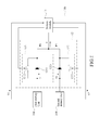
- Figure 1 shows a diagram representing an electronic assembly of the present invention.
- the present electronic assembly 100 is adapted to be coupled electrically to a first battery unit 200 and a second battery unit 300 in order to receive a first electrical power P1 and a second electrical power P2 respectively.
- the electronic assembly 100 accordingly includes a system module 11 and a parallel circuit 12.
- the system module 11 is provided with a preset threshold current value.
- the first and second battery units 200, 300 are coupled electrically to the system module 11 for transmitting of a first battery data S 1 and a second battery data S2 to the system module 11.
- the first battery data S1 and the second battery data S2 may include either a voltage value or a current value or both.
- the parallel circuit 12 is coupled electrically to the system module 11, and includes a first power diverter circuit 121 and a second power diverter circuit 122.
- the first power diverter circuit 121 consists of a first LED member 1211 and a first operation switch 1212.
- the first LED member 1211 is coupled electrically to the first battery unit 200 and the system module 11 in such a manner that a first normal bias voltage is existed between the first battery unit 200 and the system module 11.
- the first operation switch 1212 is coupled electrically to the first LED member 1211, the first battery unit 200 and the system module 11 in parallel manner.
- the second power diverter circuit 122 consists of a second LED member 1221 and a second operation switch 1222.
- the second LED member 1221 is coupled electrically to the second battery unit 300 and the system module 11 in such a manner that a second normal bias voltage is existed between the second battery unit 30 and the system module 11.
- the second operation switch 1222 is coupled electrically to the second LED member 1221, the second battery unit 300 and the system module 11 in parallel manner.
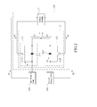
- Figure 2 shows a diagram representing the electronic assembly of the present invention in a first power supply condition.
- the first electrical power P1 is supplied via the first LED member 1211 to the system module 11, which, transmit a first switch signal S3 and a second switch signal S4 to the first operation switch 1212 and the second operation switch 1222, thereby switching the first operation switch 1212 ON and switching the second operation switch 1222 OFF in order to supply the first electrical power P1 to the system module 11 via the first operation switch 1212.
- the first electrical power P1 from the first battery unit 200 is supplied to the system module 11 without passing through the first LED member 1211, there is no loss of the first normal bias voltage so that the voltage at two ends of the first power diverter circuit 121 is not reduced, thereby providing an effective power supply to the system module 11. Because, when the electronic assembly 100 of the present invention is in the first power supply condition, the second battery unit 300 is not connected electrically to the second LED member 1221, the second electrical power P2 supplied by the second battery unit 300 is tremendously smaller than the first electrical power P1 from the first battery unit 200.
- the first operation switch 1212 can be switched ON while the second operation switch 1222 is switched OFF, thereby permitting the first battery unit 200 to supply the first electrical power P1 to the electronic assembly 100 and simultaneously permitting the second battery unit 300 is electrical communication with the assembly 100.
- one of the first and second battery units 200, 300 is hot pluggable, i.e., replacing the power-down battery unit with a new ones does not hinder the electronic assembly 100 under operation.
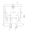
- Figure 3 shows a diagram representing the electronic assembly 100 of the present invention in a second power supply condition.
- flow of the second electrical power P2 is increased such that in case the system module 11 detects via the second battery data S2 that the second electrical power P2 is greater than the threshold current value.
- the system module 11 transmits the first switch signal S3 and the second switch signal S4 to the first operation switch 1212 and the second operation switch 1222, thereby switching the first operation switch 1212 OFF and switching the second operation switch 1222 ON and converting the electronic assembly 100 into the second power supply condition, where the second electrical power P2 is supplied to the system module 11 via the second operation switch 1222.;
- the second electrical power P2 is supplied to the system module 11 without passing through the second LED member 1221, there is no loss of the second normal bias voltage so that the voltage at two ends of the second power diverter circuit 122 is not reduced, thereby providing an effective power supply to the system module 11. Because, the first electrical power P1 is decreased, the first electrical power P1 is tremendously smaller than the second electrical power P2. In other words, when the first battery unit 200 runs low of the power, flow of the second electrical power P2 is gradually increased such that in case the first battery unit 200 is removed for replacement, supply of the second electrical power P2 can be continued effectively since the second electrical power P2 needs not pass through the second LED member 1221.
- the system module 11 is required to transmit only the first switch signal S3 to the first operation switch 1212, thereby switching the first operation switch 1212 ON in order to permit supply of the first electrical power P1 for operation of the present electronic assembly 100.
- Figure 4 shows a diagram representing the electronic assembly of the present invention in a first charging condition due to electrically coupling to an external power supply module.
- the electronic assembly 100 of the present invention is adapted to be coupled electrically to an external power supply module 400 so as to be disposed in the first power supply condition such that the system module 11 transmits the first and second switch signals S3, S4 respectively to the first and second operation switches 1212, 1222, thereby switching the first operation switch 1212 ON and switching the second operation switch 1222 OFF and converting the electronic assembly into the first charging condition, where a first charge power P3 from the power source module 400 is charged into the first battery unit 200 via the first operation switch 1212.
- Figure 5 shows a diagram representing the electronic assembly of the present invention in a second charging condition due to electrically coupling to an external power supply module.
- the system module 11 when a voltage of the first battery unit 200 is greater than the threshold current value, the system module 11 is capable of transmitting the first switch signal S3 and the second switch signal S4 to the first operation switch 1212 and the second operation switch 1222, thereby switching the first operation switch 1212 OFF and switching the second operation switch 1222 ON and converting the electronic assembly into the second charging condition, where a second charge power P4 from the power source module 400 is charged into the second battery unit 300 via the second operation switch 1222.
- the preset threshold current value is equivalent to the current value of the fully charged first battery unit 200.
- the system module 11 is required to transmit only the first switch signal S3 to the first operation switch 1212, thereby switching the first operation switch 1212 ON in order to permit charging of the first charge power P3 to the first battery unit 200 via the first operation switch 1212.
- the electronic assembly 100 of the present invention includes a parallel circuit 12 for optionally control the desired battery unit to supply the main electrical power source for operation of the electronic assembly while the reserved battery unit also simultaneously supplies electrical power source to the electronic assembly.
- the present electronic assembly is hot pluggable, i.e., in case one battery unit runs out of power during use of the assembly and the user wishes to replace a new battery unit, he can do so without the need to de-activate the electronic assembly 100 in use.
- the present electronic assembly 100 is connected electrically to the external power supply module 400 (generally called domestic power); the battery units installed therein are selectively charged, thereby facilitating the application of the present electronic assembly 100.
Landscapes
- Engineering & Computer Science (AREA)
- Power Engineering (AREA)
- Charge And Discharge Circuits For Batteries Or The Like (AREA)
- Secondary Cells (AREA)
Applications Claiming Priority (2)
| Application Number | Priority Date | Filing Date | Title |
|---|---|---|---|
| TW98141130A TW201121195A (en) | 2009-12-02 | 2009-12-02 | An electronic device which has a parallel circuit for battery |
| CN2009102598771A CN102104274A (zh) | 2009-12-02 | 2009-12-16 | 具有电池并联电路的电子装置 |
Publications (2)
| Publication Number | Publication Date |
|---|---|
| EP2330710A2 true EP2330710A2 (fr) | 2011-06-08 |
| EP2330710A3 EP2330710A3 (fr) | 2014-07-02 |
Family
ID=50158291
Family Applications (1)
| Application Number | Title | Priority Date | Filing Date |
|---|---|---|---|
| EP09180125.8A Withdrawn EP2330710A3 (fr) | 2009-12-02 | 2009-12-21 | Ensemble électronique équipé d'un circuit parallèle pour connecter électriquement deux unités de batterie |
Country Status (5)
| Country | Link |
|---|---|
| US (1) | US8253277B2 (fr) |
| EP (1) | EP2330710A3 (fr) |
| JP (1) | JP2011120436A (fr) |
| CN (1) | CN102104274A (fr) |
| TW (1) | TW201121195A (fr) |
Cited By (1)
| Publication number | Priority date | Publication date | Assignee | Title |
|---|---|---|---|---|
| CN107757375A (zh) * | 2017-11-26 | 2018-03-06 | 安徽星凯龙客车有限公司 | 一种双电池充放电切换控制系统和方法 |
Families Citing this family (28)
| Publication number | Priority date | Publication date | Assignee | Title |
|---|---|---|---|---|
| KR101769469B1 (ko) * | 2010-11-02 | 2017-08-18 | 에스프린팅솔루션 주식회사 | 화상형성장치 |
| WO2012112147A1 (fr) * | 2011-02-16 | 2012-08-23 | Hewlett-Packard Development Company, L.P. | Alimentation électrique d'un dispositif électronique |
| US8941264B2 (en) * | 2011-06-20 | 2015-01-27 | Bae Systems Information And Electronic Systems Integration Inc. | Apparatus for bi-directional power switching in low voltage vehicle power distribution systems |
| CN102577336A (zh) * | 2011-07-21 | 2012-07-11 | 华为终端有限公司 | 一种无线宽带设备 |
| TWI556546B (zh) * | 2011-08-30 | 2016-11-01 | Electric car battery parallel protection device | |
| CN102957180A (zh) * | 2011-08-31 | 2013-03-06 | 湖南丰日电源电气股份有限公司 | 蓄电池安全并联装置 |
| CN102651572B (zh) * | 2012-05-10 | 2014-07-09 | 华为技术有限公司 | 一种零时备电系统和零时备电方法 |
| TWI477017B (zh) * | 2012-07-24 | 2015-03-11 | 光寶科技股份有限公司 | 避免電池浮充之控制系統、供電系統及方法 |
| CA2879956C (fr) * | 2012-07-25 | 2017-08-01 | Toshiba Mitsubishi-Electric Industrial Systems Corporation | Systeme d'alimentation |
| CN203552016U (zh) * | 2012-08-14 | 2014-04-16 | 费希尔控制国际公司 | 控制信号保护设备及其控制系统 |
| CN102832695A (zh) * | 2012-08-28 | 2012-12-19 | 江苏力天新能源科技有限公司 | 用于更换通信备用电池的装置 |
| CN103683210B (zh) * | 2012-09-18 | 2018-09-14 | 深圳市海洋王照明工程有限公司 | 充放电保护电路及应用其的防爆灯具 |
| CN103268075B (zh) * | 2013-04-27 | 2016-03-02 | 浙江宇视科技有限公司 | 一种电源反送装置 |
| JP6048313B2 (ja) * | 2013-05-27 | 2016-12-21 | 株式会社デンソー | 電源装置 |
| CN104467169B (zh) * | 2014-12-26 | 2016-10-05 | 深圳警翼数码科技有限公司 | 一种不间断供电装置 |
| CN106740206B (zh) * | 2015-02-09 | 2020-07-21 | 浙江吉利汽车研究院有限公司 | 电动车电池包的快换方法及快换系统 |
| US10063049B1 (en) * | 2015-09-30 | 2018-08-28 | Juniper Networks, Inc. | Apparatus, system, and method for improving the power efficiency of telecommunications devices |
| CN105305572A (zh) * | 2015-12-04 | 2016-02-03 | 杭州电子科技大学 | 一种安全热插拔式电池电源系统 |
| CN105490341A (zh) * | 2015-12-28 | 2016-04-13 | 深圳市基伍智联科技有限公司 | 具有双电池功能的智能手机 |
| CN105529742A (zh) * | 2016-02-18 | 2016-04-27 | 江西洪都航空工业集团有限责任公司 | 一种耐环境过载反向隔离型大功率电源并网的控制方法 |
| CN108808831A (zh) * | 2017-12-15 | 2018-11-13 | 苏州沸迩灵精密制造有限公司 | 一种不断电更换电池的电路 |
| CN108427496A (zh) * | 2018-02-14 | 2018-08-21 | 合肥联宝信息技术有限公司 | 一种控制方法及电子设备 |
| TWI729552B (zh) | 2019-11-04 | 2021-06-01 | 廣達電腦股份有限公司 | 操作電路 |
| WO2021109628A1 (fr) * | 2019-12-03 | 2021-06-10 | 国网江苏省电力有限公司电力科学研究院 | Dispositif de distribution d'énergie de courant continu à basse tension et de commutation rapide |
| WO2021207815A1 (fr) * | 2020-04-15 | 2021-10-21 | Acumuladores Moura S/A | Procédé de d'actionnement et de fonctionnement d'un système de montage et de commande d'accumulateurs au niveau de stations de travail |
| CN111769541B (zh) * | 2020-07-29 | 2022-03-15 | 深圳市绿联科技股份有限公司 | 一种供电电路、防止电压倒流的终端附件和方法 |
| CN112510810B (zh) * | 2020-12-07 | 2023-04-11 | 中国第一汽车股份有限公司 | 一种汽车及其电源系统的监控电路 |
| CN115626129A (zh) * | 2022-11-14 | 2023-01-20 | 江苏辰特动力有限公司 | 一种车载电源切换电路及车辆 |
Family Cites Families (12)
| Publication number | Priority date | Publication date | Assignee | Title |
|---|---|---|---|---|
| FR2514963A1 (fr) * | 1981-10-20 | 1983-04-22 | Accumulateurs Fixes | Dispositif de charge d'un ensemble de batteries, notamment de batteries tampons alimentees par une source d'energie de puissance limitee |
| US5598041A (en) * | 1995-11-16 | 1997-01-28 | Lockheed Martin Corporation | Efficient fault tolerant switching circuit for redundant d. c. power supplies |
| JPH09238429A (ja) * | 1996-02-29 | 1997-09-09 | Canon Inc | 二次電池電源装置 |
| JPH11234915A (ja) * | 1998-02-20 | 1999-08-27 | Fujitsu Ltd | 充電可能な電池を備えた電源装置、および複数の電池の充電/放電方法 |
| US6977482B2 (en) * | 2003-02-11 | 2005-12-20 | O2Micro International Limited | Selector circuit for power management in multiple battery systems |
| JP2002142375A (ja) * | 2000-10-30 | 2002-05-17 | Nippon Telegr & Teleph Corp <Ntt> | 蓄電装置およびその制御方法 |
| US6864669B1 (en) * | 2002-05-02 | 2005-03-08 | O2Micro International Limited | Power supply block with simplified switch configuration |
| US6879134B2 (en) * | 2003-02-11 | 2005-04-12 | O2Micro International Limited | Selector circuit for power management in multiple battery systems |
| US20070273216A1 (en) * | 2006-05-24 | 2007-11-29 | Farbarik John M | Systems and Methods for Reducing Power Losses in a Medical Device |
| DE102006040753B4 (de) * | 2006-08-31 | 2012-06-21 | Knorr-Bremse Systeme für Nutzfahrzeuge GmbH | Redundante Stromversorgung mit Diagnosefähigkeit und Schutzbeschaltung |
| JP2008086148A (ja) * | 2006-09-28 | 2008-04-10 | Brother Ind Ltd | 電源回路 |
| CN201146398Y (zh) * | 2008-01-03 | 2008-11-05 | 无敌科技(西安)有限公司 | 电子装置的电源电路 |
-
2009
- 2009-12-02 TW TW98141130A patent/TW201121195A/zh unknown
- 2009-12-16 CN CN2009102598771A patent/CN102104274A/zh active Pending
- 2009-12-21 EP EP09180125.8A patent/EP2330710A3/fr not_active Withdrawn
- 2009-12-22 JP JP2009291393A patent/JP2011120436A/ja active Pending
- 2009-12-29 US US12/648,877 patent/US8253277B2/en not_active Expired - Fee Related
Non-Patent Citations (1)
| Title |
|---|
| None |
Cited By (2)
| Publication number | Priority date | Publication date | Assignee | Title |
|---|---|---|---|---|
| CN107757375A (zh) * | 2017-11-26 | 2018-03-06 | 安徽星凯龙客车有限公司 | 一种双电池充放电切换控制系统和方法 |
| CN107757375B (zh) * | 2017-11-26 | 2020-09-25 | 安徽星凯龙客车有限公司 | 一种双电池充放电切换控制系统和方法 |
Also Published As
| Publication number | Publication date |
|---|---|
| CN102104274A (zh) | 2011-06-22 |
| EP2330710A3 (fr) | 2014-07-02 |
| JP2011120436A (ja) | 2011-06-16 |
| TW201121195A (en) | 2011-06-16 |
| US20110080048A1 (en) | 2011-04-07 |
| US8253277B2 (en) | 2012-08-28 |
Similar Documents
| Publication | Publication Date | Title |
|---|---|---|
| US8253277B2 (en) | Electronic assembly provided with a parallel circuit for connecting electrically to two battery units | |
| EP2325967B1 (fr) | Alimentation électrique avec mécanisme de protection contre les éclairs d'arc et système de traitement de données l'employant | |
| KR101445011B1 (ko) | 장치 충전 동안의 슬리프 모드와 정상 모드 간의 토글링 시에 감소된 전력 소모를 갖는 전력 컨버터 | |
| US20080290731A1 (en) | Energy Efficient Power Supply | |
| CN103915863B (zh) | 终端设备及其供电方法 | |
| CN101882701B (zh) | 一种充电的方法及系统 | |
| CN110474391B (zh) | 充电电路及电子设备 | |
| US11249448B2 (en) | Devices, control modules, and controllers | |
| US20090267418A1 (en) | Switch power supply and electronic device having same | |
| CN105426332B (zh) | 通讯接口电路、便携式电子设备及电子系统 | |
| JP2017513441A (ja) | 電気多モード電力変換器モジュールおよび電力システム | |
| US8667314B2 (en) | Power switching circuit of portable electronic device | |
| US20080012524A1 (en) | Chargeable electronic devices and direct current voltage supply systems | |
| CN111786427A (zh) | 一种用于无线耳机的充电盒及无线耳机产品组件 | |
| CN110138404B (zh) | 用于向保护和控制设备提供无线连接的收发器设备 | |
| TWM564287U (zh) | 一種具有電源管理能力的多電腦切換裝置 | |
| US20090206671A1 (en) | Backup power system equipped with independent protection circuit architecture | |
| EP1766497B1 (fr) | Systeme et procede d'acheminement de donnees et d'energie vers des dispositifs externes | |
| CN101232112A (zh) | 电子设备的供电方法 | |
| JP2006230029A (ja) | 無停電電源装置 | |
| CN101359836A (zh) | 一种自切换充电电路 | |
| CN216774599U (zh) | 一种供电转换设备及电子设备 | |
| JP2005261142A (ja) | 充電回路 | |
| CN102541666B (zh) | 一种电子设备和保护电子设备内部器件的方法 | |
| CN110417083B (zh) | 一种外部设备供电装置 |
Legal Events
| Date | Code | Title | Description |
|---|---|---|---|
| PUAI | Public reference made under article 153(3) epc to a published international application that has entered the european phase |
Free format text: ORIGINAL CODE: 0009012 |
|
| AK | Designated contracting states |
Kind code of ref document: A2 Designated state(s): AT BE BG CH CY CZ DE DK EE ES FI FR GB GR HR HU IE IS IT LI LT LU LV MC MK MT NL NO PL PT RO SE SI SK SM TR |
|
| AX | Request for extension of the european patent |
Extension state: AL BA RS |
|
| 17P | Request for examination filed |
Effective date: 20111205 |
|
| RAP1 | Party data changed (applicant data changed or rights of an application transferred) |
Owner name: GIGA-BYTE TECHNOLOGY CO., LTD. |
|
| PUAL | Search report despatched |
Free format text: ORIGINAL CODE: 0009013 |
|
| RIC1 | Information provided on ipc code assigned before grant |
Ipc: H02J 7/34 20060101ALI20140522BHEP Ipc: H02J 7/36 20060101ALI20140522BHEP Ipc: H02J 1/10 20060101AFI20140522BHEP Ipc: H02J 7/00 20060101ALI20140522BHEP |
|
| AK | Designated contracting states |
Kind code of ref document: A3 Designated state(s): AT BE BG CH CY CZ DE DK EE ES FI FR GB GR HR HU IE IS IT LI LT LU LV MC MK MT NL NO PL PT RO SE SI SK SM TR |
|
| AX | Request for extension of the european patent |
Extension state: AL BA RS |
|
| STAA | Information on the status of an ep patent application or granted ep patent |
Free format text: STATUS: THE APPLICATION IS DEEMED TO BE WITHDRAWN |
|
| 18D | Application deemed to be withdrawn |
Effective date: 20150106 |