EP2331280B1 - Material removal tool with actuated guide pads - Google Patents
Material removal tool with actuated guide pads Download PDFInfo
- Publication number
- EP2331280B1 EP2331280B1 EP09811893.8A EP09811893A EP2331280B1 EP 2331280 B1 EP2331280 B1 EP 2331280B1 EP 09811893 A EP09811893 A EP 09811893A EP 2331280 B1 EP2331280 B1 EP 2331280B1
- Authority
- EP
- European Patent Office
- Prior art keywords
- guide pad
- material removal
- removal tool
- active portion
- differential pressure
- Prior art date
- Legal status (The legal status is an assumption and is not a legal conclusion. Google has not performed a legal analysis and makes no representation as to the accuracy of the status listed.)
- Not-in-force
Links
- 239000000463 material Substances 0.000 title claims description 72
- 230000013011 mating Effects 0.000 claims description 30
- 239000012530 fluid Substances 0.000 claims description 25
- 238000005520 cutting process Methods 0.000 claims description 24
- 238000000034 method Methods 0.000 claims description 17
- 239000000314 lubricant Substances 0.000 claims description 7
- 238000004513 sizing Methods 0.000 claims description 2
- 238000013022 venting Methods 0.000 claims description 2
- 230000007704 transition Effects 0.000 description 7
- 238000003754 machining Methods 0.000 description 4
- 238000013519 translation Methods 0.000 description 4
- 238000005452 bending Methods 0.000 description 3
- 238000007789 sealing Methods 0.000 description 3
- 238000013461 design Methods 0.000 description 2
- 230000000694 effects Effects 0.000 description 2
- 238000003860 storage Methods 0.000 description 2
- 230000004323 axial length Effects 0.000 description 1
- 238000007796 conventional method Methods 0.000 description 1
- 238000001816 cooling Methods 0.000 description 1
- 238000003780 insertion Methods 0.000 description 1
- 230000037431 insertion Effects 0.000 description 1
- 238000005461 lubrication Methods 0.000 description 1
- 238000003801 milling Methods 0.000 description 1
Images



Classifications
-
- B—PERFORMING OPERATIONS; TRANSPORTING
- B23—MACHINE TOOLS; METAL-WORKING NOT OTHERWISE PROVIDED FOR
- B23B—TURNING; BORING
- B23B35/00—Methods for boring or drilling, or for working essentially requiring the use of boring or drilling machines; Use of auxiliary equipment in connection with such methods
-
- B—PERFORMING OPERATIONS; TRANSPORTING
- B23—MACHINE TOOLS; METAL-WORKING NOT OTHERWISE PROVIDED FOR
- B23B—TURNING; BORING
- B23B29/00—Holders for non-rotary cutting tools; Boring bars or boring heads; Accessories for tool holders
- B23B29/02—Boring bars
-
- B—PERFORMING OPERATIONS; TRANSPORTING
- B23—MACHINE TOOLS; METAL-WORKING NOT OTHERWISE PROVIDED FOR
- B23B—TURNING; BORING
- B23B2229/00—Details of boring bars or boring heads
- B23B2229/04—Guiding pads
-
- B—PERFORMING OPERATIONS; TRANSPORTING
- B23—MACHINE TOOLS; METAL-WORKING NOT OTHERWISE PROVIDED FOR
- B23B—TURNING; BORING
- B23B2251/00—Details of tools for drilling machines
- B23B2251/56—Guiding pads
-
- B—PERFORMING OPERATIONS; TRANSPORTING
- B23—MACHINE TOOLS; METAL-WORKING NOT OTHERWISE PROVIDED FOR
- B23B—TURNING; BORING
- B23B2270/00—Details of turning, boring or drilling machines, processes or tools not otherwise provided for
- B23B2270/24—Tool, chuck or other device activated by the coolant or lubrication system of the machine tool
-
- Y—GENERAL TAGGING OF NEW TECHNOLOGICAL DEVELOPMENTS; GENERAL TAGGING OF CROSS-SECTIONAL TECHNOLOGIES SPANNING OVER SEVERAL SECTIONS OF THE IPC; TECHNICAL SUBJECTS COVERED BY FORMER USPC CROSS-REFERENCE ART COLLECTIONS [XRACs] AND DIGESTS
- Y10—TECHNICAL SUBJECTS COVERED BY FORMER USPC
- Y10T—TECHNICAL SUBJECTS COVERED BY FORMER US CLASSIFICATION
- Y10T408/00—Cutting by use of rotating axially moving tool
- Y10T408/03—Processes
-
- Y—GENERAL TAGGING OF NEW TECHNOLOGICAL DEVELOPMENTS; GENERAL TAGGING OF CROSS-SECTIONAL TECHNOLOGIES SPANNING OVER SEVERAL SECTIONS OF THE IPC; TECHNICAL SUBJECTS COVERED BY FORMER USPC CROSS-REFERENCE ART COLLECTIONS [XRACs] AND DIGESTS
- Y10—TECHNICAL SUBJECTS COVERED BY FORMER USPC
- Y10T—TECHNICAL SUBJECTS COVERED BY FORMER US CLASSIFICATION
- Y10T408/00—Cutting by use of rotating axially moving tool
- Y10T408/44—Cutting by use of rotating axially moving tool with means to apply transient, fluent medium to work or product
- Y10T408/45—Cutting by use of rotating axially moving tool with means to apply transient, fluent medium to work or product including Tool with duct
-
- Y—GENERAL TAGGING OF NEW TECHNOLOGICAL DEVELOPMENTS; GENERAL TAGGING OF CROSS-SECTIONAL TECHNOLOGIES SPANNING OVER SEVERAL SECTIONS OF THE IPC; TECHNICAL SUBJECTS COVERED BY FORMER USPC CROSS-REFERENCE ART COLLECTIONS [XRACs] AND DIGESTS
- Y10—TECHNICAL SUBJECTS COVERED BY FORMER USPC
- Y10T—TECHNICAL SUBJECTS COVERED BY FORMER US CLASSIFICATION
- Y10T408/00—Cutting by use of rotating axially moving tool
- Y10T408/55—Cutting by use of rotating axially moving tool with work-engaging structure other than Tool or tool-support
- Y10T408/557—Frictionally engaging sides of opening in work
-
- Y—GENERAL TAGGING OF NEW TECHNOLOGICAL DEVELOPMENTS; GENERAL TAGGING OF CROSS-SECTIONAL TECHNOLOGIES SPANNING OVER SEVERAL SECTIONS OF THE IPC; TECHNICAL SUBJECTS COVERED BY FORMER USPC CROSS-REFERENCE ART COLLECTIONS [XRACs] AND DIGESTS
- Y10—TECHNICAL SUBJECTS COVERED BY FORMER USPC
- Y10T—TECHNICAL SUBJECTS COVERED BY FORMER US CLASSIFICATION
- Y10T408/00—Cutting by use of rotating axially moving tool
- Y10T408/55—Cutting by use of rotating axially moving tool with work-engaging structure other than Tool or tool-support
- Y10T408/557—Frictionally engaging sides of opening in work
- Y10T408/558—Opening coaxial with Tool
- Y10T408/5583—Engaging sides of opening being enlarged by Tool
- Y10T408/5586—Engaging surface subsequent to tool-action on that surface
-
- Y—GENERAL TAGGING OF NEW TECHNOLOGICAL DEVELOPMENTS; GENERAL TAGGING OF CROSS-SECTIONAL TECHNOLOGIES SPANNING OVER SEVERAL SECTIONS OF THE IPC; TECHNICAL SUBJECTS COVERED BY FORMER USPC CROSS-REFERENCE ART COLLECTIONS [XRACs] AND DIGESTS
- Y10—TECHNICAL SUBJECTS COVERED BY FORMER USPC
- Y10T—TECHNICAL SUBJECTS COVERED BY FORMER US CLASSIFICATION
- Y10T408/00—Cutting by use of rotating axially moving tool
- Y10T408/83—Tool-support with means to move Tool relative to tool-support
- Y10T408/85—Tool-support with means to move Tool relative to tool-support to move radially
Definitions
- the present disclosure relates to a material removal tool with guide pads that can be radially translated by an actuation fluid.
- a material removal tool is known from US 3,389,621 .
- Material removal tools with cutting locations positioned at a long projection distance from a spindle face can experience bending moments caused by cutting forces. Uncorrected bending moments can result in machining errors and other out-of-tolerance effects.
- Conventional methods to address bending moments in these tools have included fixing a ground wear strip to an end of the tool and to insert the end of the tool in a mating hole, thus providing support for the tool at both ends of the axis of the tool.
- Such wear strips require very tight tolerances to adequately position and support the end of the tool in the mating hole.
- a ground bushing is generally required to accept the ground pads.
- such mating holes must be already cut for the wear pads to work requiring a cutting edge to precede the wear pads.
- US 3,389,621 discloses a boring tool comprising a cutting head for machining deep bores.
- the cutting head comprises a burnishing insert being movable radially outward by fluid pressure against action of a spring.
- the movable insert is attached to a piston slidable in a radial bore in the cutting head and the pressure fluid acts on the inner side of the piston to move the piston outward.
- the piston is biased inwardly by a spring also located in the radial bore.
- the presently disclosed material removal tool has radially adjustable guide pads.
- the radially adjustable guide pads can be repositioned, in-operation, to stabilize and/or centralize the material cutting tool, requiring lower tolerances while supporting the end of the tool in the mating hole.
- This design is applicable to any material removal tool with a long overhang from the spindle face and is particularly applicable to line boring and thrust wall tools on cylinder blocks when using CNC machining centers.
- the material removal tool according to the present invention is defined by the features of independent claim 1. Moreover, a method for removing material from a workpiece in accordance with the present invention is defined by independent claim 11.
- An exemplary material removal tool comprises a housing body including an active portion, at least one seating surface for a cutting insert operatively positioned on the active portion, and a guide pad positioned in a cavity in a circumferential surface of the active portion, wherein the guide pad is radially adjustable between a first radial position and a second radial position by a differential pressure across the guide pad.
- An exemplary method for removing material from a workpiece with a rotating material removal tool comprises positioning a distal end of an active portion of the material removal tool in a mating hole in the workpiece to locate at least a portion of a guide pad in opposing relationship to a surface of the mating hole, wherein the guide pad is positioned in a cavity in a circumferential surface of the active portion, and developing a differential pressure across the guide pad to translate the guide pad radially outward.
- the actuation fluid is a lubricant and the vented actuation fluid supplies the lubricant to the second side of the guide pad.
- the method involves sizing the channel in the guide pad to obtain a desired value of the differential pressure.
- the second side is a radially outermost surface of the guide pad.
- the method involves positioning an o-ring in a circumferential groove in the guide pad to seal the guide pad in the cavity to develop the differential pressure.
- the method comprising relieving a differential pressure across the guide pad to translate the guide pad radially inward and withdrawing the distal end of the active portion of the material removal tool from the mating hole in the workpiece.
- FIG. 1 is perspective view of an exemplary embodiment of a material removal tool 2.
- the material removal tool can be generally described as having a housing with an active portion and a mounting portion.
- the housing 10 includes an active portion I separated from the mounting portion II at a transition line 12.
- the transition line 12 can be coincident with the transition piece 14 or can be at a different location of the material removal tool 2, although generally in the area of the actuation chamber housing 16.
- the active portion I is placed near or, for example during boring, inserted into the volume of the workpiece.
- the mounting portion II is generally not operatively positioned within the volume of the workpiece. Thus, only locations and features on the active portion I are available for material removal operations.
- the active portion I generally has a regular shape, e.g., cylindrical, and has a different diameter than that of the mounting portion II.
- the diameter at any point of the active portion I is substantially constant along its axial length and an active volume of the material removal tool 2 can be defined as the volume occupied by the rotating material removal tool based on that diameter of the active portion I.
- an active volume can be defined as the volume occupied by the rotating material removal tool based on the largest diameter at any point of the active portion.
- the cutting features 18 include at least one seating surface for a cutting insert operatively positioned on the active portion to allow the material removal tool 2 to perform cutting operations.
- the guide pads 20 are located proximate a first end 22 of the active portion I. When mounted on a machine tool, the first end 22 is a distal end relative to the machine tool.
- Other features include various openings, connectors and manipulators for assembly and operation of the material removal tool 2, as are known in the art.
- the mounting portion II includes a connector 24 at a second end 26, which is a mating end for attachment to the machine tool.
- the connector 24 attaches to a machine tool, such as a MAG XS211 milling machine available from MAG Industrial Automation Systems, for operation.
- the connector 24 can take any suitable form that allows attachment to a desired machine tool, e.g., attachment to a spindle of the machine tool.
- the connector 24 has a tapered surface 28, for example, tapered rearward or toward the second end 26.
- a transition piece 30 can optionally be included with the connector 24.
- a transition piece 30 includes at least one feature for mating to an operating machine or to a storage system.
- the transition piece 30 can include a circumferential groove 32.
- the circumferential groove 32, or similar structure can provide an attachment point for mating the material removal tool 2 to a carousel storage system used in machining operations to store multiple material removal tools.
- the transition piece 30 can include a key slot or similar structure, which can provide an orientation or a mating with a corresponding feature on the machine tool when the material removal tool 2 is mounted for use.
- FIG. 2 A magnified view of the first end 22 of the active portion I of the material removal tool 2 is shown in FIG. 2 and a partially disassembled view of some of the components located proximate the first end 22 of the active portion I of the material removal 2 is shown in FIG. 3 .
- the plurality of guide pads 20 are positioned in a cavity 34 in a circumferential surface 36 of the active portion I of the material removal tool 2.
- One or more stops 38 hold the guide pad 20 in the cavity 34.
- the stop 38 can be mounted by a fastener, such as the threaded screw 40 shown. In some embodiments, the stop 38 allows the guide pad 20 to move radially within the cavity 34 but also limits the movement of the guide pad 20 in the radially outward direction.
- the guide pad 20 translates radially outward to contact the surface of a mating hole, as described further herein.
- the cavity 34 can be of a single depth or can have more than one depth, as shown in FIG. 3 , as necessary to accommodate the geometry of the guide pad 20 and associated features, such as the stops 38.
- the guide pad 20 includes a channel 42 extending from a first side 44 of the guide pad 20 to a second side 46 of the guide pad 20.
- the channel 42 on the first side 44 opens into the portion of the cavity 34 below the guide pad 20 and the channel 42 on the second side 46 opens into a groove 48 on the surface of the second side 46.
- the groove 48 assists in distributing lubricant fluid exiting the channel 42 on the second side 46, as described further herein.
- the second side 46 of the guide pad 20 is the radially outward surface of the guide pad 20.
- the guide pad 20 is radially adjustable between a first radial position and a second radial position.
- a first radial position of the guide pad 20 can be a retracted position. In the retracted position, a radially outermost surface of the second side 46 of the guide pad 20 is at a first radial distance from an axis 50 of the material removal tool 2 where the first radial distance is less than a radial distance from the axis 50 of the outer circumferential surface 36 of the active portion I.
- a second radial position of the guide pad 20 can be an extended position.
- a radially outermost surface of the second side 46 of the guide pad 20 is at a second radial distance from the axis 50 of the material removal tool 2 where the second radial distance is greater than a radial distance of the outer circumferential surface of the active portion.
- the extended position contacts the second side 46 of the guide pad 20 with the surface of a mating hole, as described further herein.
- the guide pad 20 is radially adjustable between the first radial position and the second radial position by a differential pressure (asp) across the guide pad 20.
- An actuation fluid is supplied to the cavity 34 below the guide pad 20.
- opening 52 in the wall of the cavity 34 can supply an actuation fluid from system of channels arranged internally within the material removal tool 2.
- the differential pressure can be controlled or adjusted by any suitable means.
- the channel 42 can vent the actuation fluid from the first side 44 to the second side 46.
- a shape and/or size of the channel 42 can control a value of the differential pressure.
- the relative shapes and/or sizes of the radial cross-section of the opening 52 supplying the actuation fluid and the radial cross-section of the channel 42 in the guide pad 20 can be changed, i.e., the radial cross-section of the opening 52 can be greater than the radial cross-section of the channel 42.
- a surface area of the first side 44 of the guide pad 20 can influence the value of the differential pressure, with a smaller surface area increasing the differential pressure and vice versa.
- the channel 42 can vent the actuation fluid from the first side 44 of the guide pad 20 to the second side 46 of the guide pad 20.
- the channel 42 opens into a groove 48 on the second side of the guide pad 20.
- the groove 48 distributes the actuation fluid along the length of the guide pad 20 and, when the guide pad 20 rotates in unison with the material removal tool 2 during cutting operations, the distributed actuation fluid further distributes across the surface of the second side 46 of the guide pad 20.
- the actuation fluid which can be a lubricant, can provide cooling and lubrication to the guide pads, the first end of the material removal tool, the mating hole in which the first end is positioned and any interfaces therebetween.
- the groove 48 is located near the leading edge 56 of the guide pad 20.
- the leading edge 56 is that edge of the guide pad 20 that, when the guide pad 20 is positioned in the cavity 34 and the material removal tool 2 is rotated for cutting operations, is in a foremost position in the rotational direction.
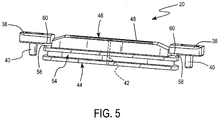
- FIG. 4 is a first perspective view of an exemplary embodiment of a guide pad 20 and FIG. 5 is a second perspective view of an exemplary embodiment of a guide pad 20.
- the guide pad 20 has an extension 58 at each end which interacts with capture surfaces 60 on the stops 38 to restrain the guide pad's radial movement in the cavity 34.
- Material removal tools as disclosed herein can be used for cutting operations. Relative to surfaces of a workpiece to be machined, the guide pads 20 precede cutting features 18.
- the actuating guide pads 20 can retract downward below the outer circumferential surface 36 of the material removal tool 2 to allow insertion into bores smaller than the finished part.
- Cutting elements on the cutting features 18 can then be extended by mechanical or other means for cutting operations, e.g., to finish the part. Because the actuating pads are at least partially inserted in a mating hole, the material removal tool is better supported and the effects of cutting forces are reduced, thus allowing for a straighter bore or face.
- a distal end of an active portion of the material removal tool is positioned in a mating hole in the workpiece to locate at least a portion of a guide pad in opposing relationship to a surface of the mating hole.
- a differential pressure is then developed across the guide pad to translate the guide pad radially outward.
- the guide pads 20 float in the cavity 34 but also form a seal (with sealing member 62, e.g., an o-ring) whereby a differential pressure can be made across the guide pad 20.
- the actuations fluid is supplied to the cavities 34 by conduits 64 internal to the material removal tool.
- the actuation fluid is vented through the channel 42, which has a smaller diameter than the opening 52, to establish and maintain the differential pressure.
- the relative sizes of channel 42 and the opening 52 can be varied to form a desired differential pressure, which translates the guide pad 20 in the radial direction.
- the guide pad 20 generally translates between an innermost position where the first side 44 is proximal the bottom surface 66 of the cavity 34 to an outermost position where the extensions 58 are restrained by capture surfaces 60 anchored by fastening mechanism or to an outermost position where the guide pad 20 translation is limited by the surface of the mating hole.
- FIGS. 6A to 6C schematically illustrate cross-sections of a material removal tool in a mating hole showing the guide pads in different actuation positions.
- the guide pads can be actuated for radial adjustment collectively or individually depending on the control of the differential pressure to each. However, collective operation is considered more common.
- FIG. 6A schematically illustrates the guide pads 20 in a retracted position.
- the guide pads 20 are in the cavity 34 with the second side 46 below the outer circumferential surface 36 of the active portion I.
- the first side 44 of the guide pad 20 is in contact with a bottom surface 66 of the cavity 34.
- FIG. 6B schematically illustrates the guide pads 20 adjusted to an extended position, where the guide pads 20 have been radial translated outward to contact the surface 68 of the mating hole.
- An actuation fluid has been supplied to the cavity 34 behind the first side 44 of the guide pad 20 and a differential pressure established across the guide pad 20. This differential pressure has translated the guide pad 20 radially outward. This outward radial translation is limited because the second side 46 of the guide pad 20 contacts the surface 68 of the mating hole.
- the stops 38 are not contacted by the extensions 58 and there is a space 70 between the capture surfaces 60 and the extensions 58.
- FIG. 6C schematically illustrates the guide pads 20 adjusted to an extended position, where the radial translation of the guide pads 20 is limited by the stops 38.
- the differential pressure can be controlled to adjust the amount of friction between the guide pads and the surface of the mating hole. Too much friction inhibits rotation and can damages surfaces; too little friction produces inadequate support for the material removal tool.
- the differential pressure can be controlled, e.g., by controlling the channel and/or opening geometry and size, amongst the several guide pads to be substantially (i.e., within ⁇ 10%) the same. Substantially (i.e., within ⁇ 10%) uniform differential pressure amongst the several guide pads contributes to centering the first end 22 of the material removal tool 2 in the mating hole.
- the differential pressure across the guide pad is relieved to translate the guide pad radially inward.
- the distal end of the active portion of the material removal tool can then be withdrawn from the mating hole in the workpiece.
- Relieving the differential pressure can be a reduction from the differential pressure established to translate the guide pads radially outward, can be a venting of differential pressure toward zero, or can be a removal of differential pressure to zero.
- Translation in this instance is passive, in that the guide pads are free to translate radially inward, but are not forced to retract.
- a biasing element such as an axial spring between the extensions 58 and capture surfaces 60, can force retraction of the guide pad. Inclusion of a biasing element can make the design more complicated.
Landscapes
- Engineering & Computer Science (AREA)
- Mechanical Engineering (AREA)
- Drilling Tools (AREA)
- Milling Processes (AREA)
Description
- The present disclosure relates to a material removal tool with guide pads that can be radially translated by an actuation fluid. Such a material removal tool is known from
US 3,389,621 . - Material removal tools with cutting locations positioned at a long projection distance from a spindle face can experience bending moments caused by cutting forces. Uncorrected bending moments can result in machining errors and other out-of-tolerance effects. Conventional methods to address bending moments in these tools have included fixing a ground wear strip to an end of the tool and to insert the end of the tool in a mating hole, thus providing support for the tool at both ends of the axis of the tool. Such wear strips require very tight tolerances to adequately position and support the end of the tool in the mating hole. For example, a ground bushing is generally required to accept the ground pads. Also, such mating holes must be already cut for the wear pads to work requiring a cutting edge to precede the wear pads.
-
US 3,389,621 discloses a boring tool comprising a cutting head for machining deep bores. The cutting head comprises a burnishing insert being movable radially outward by fluid pressure against action of a spring. The movable insert is attached to a piston slidable in a radial bore in the cutting head and the pressure fluid acts on the inner side of the piston to move the piston outward. The piston is biased inwardly by a spring also located in the radial bore. - The presently disclosed material removal tool has radially adjustable guide pads. The radially adjustable guide pads can be repositioned, in-operation, to stabilize and/or centralize the material cutting tool, requiring lower tolerances while supporting the end of the tool in the mating hole. This design is applicable to any material removal tool with a long overhang from the spindle face and is particularly applicable to line boring and thrust wall tools on cylinder blocks when using CNC machining centers.
- The material removal tool according to the present invention is defined by the features of independent claim 1. Moreover, a method for removing material from a workpiece in accordance with the present invention is defined by independent claim 11.
- An exemplary material removal tool comprises a housing body including an active portion, at least one seating surface for a cutting insert operatively positioned on the active portion, and a guide pad positioned in a cavity in a circumferential surface of the active portion, wherein the guide pad is radially adjustable between a first radial position and a second radial position by a differential pressure across the guide pad.
- An exemplary method for removing material from a workpiece with a rotating material removal tool comprises positioning a distal end of an active portion of the material removal tool in a mating hole in the workpiece to locate at least a portion of a guide pad in opposing relationship to a surface of the mating hole, wherein the guide pad is positioned in a cavity in a circumferential surface of the active portion, and developing a differential pressure across the guide pad to translate the guide pad radially outward. The actuation fluid is a lubricant and the vented actuation fluid supplies the lubricant to the second side of the guide pad. In further embodiments of the claimed method the method involves sizing the channel in the guide pad to obtain a desired value of the differential pressure. In further embodiments of the claimed method the second side is a radially outermost surface of the guide pad. In further embodiments of the claimed method the method involves positioning an o-ring in a circumferential groove in the guide pad to seal the guide pad in the cavity to develop the differential pressure. In further embodiments of the claimed method the method comprising relieving a differential pressure across the guide pad to translate the guide pad radially inward and withdrawing the distal end of the active portion of the material removal tool from the mating hole in the workpiece.
- It is to be understood that both the foregoing general description and the following detailed description are exemplary and explanatory and are intended to provide further explanation of the invention as claimed.
- The following detailed description can be read in connection with the accompanying drawings in which like numerals designate like elements and in which:
-
FIG. 1 is perspective view of an exemplary embodiment of a material removal tool. -
FIG. 2 is a magnified view of an active portion of the material removal showing the guide pads located proximate a first end thereof. -
FIG. 3 is a partially disassembled view of some of the components located proximate the first end of the active portion of the material removal. -
FIG. 4 is a first perspective view of an exemplary embodiment of a guide pad. -
FIG. 5 is a second perspective view of an exemplary embodiment of a guide pad. -
FIGS. 6A to 6C schematically illustrate cross-sections of a material removal tool in a mating hole showing the guide pads in different actuation positions. -
FIG. 1 is perspective view of an exemplary embodiment of amaterial removal tool 2. The material removal tool can be generally described as having a housing with an active portion and a mounting portion. Referring to the exemplary embodiment ofFIG. 1 , thehousing 10 includes an active portion I separated from the mounting portion II at atransition line 12. Thetransition line 12 can be coincident with thetransition piece 14 or can be at a different location of thematerial removal tool 2, although generally in the area of theactuation chamber housing 16. During cutting operations, the active portion I is placed near or, for example during boring, inserted into the volume of the workpiece. The mounting portion II is generally not operatively positioned within the volume of the workpiece. Thus, only locations and features on the active portion I are available for material removal operations. - In the exemplary embodiment of
FIG. 1 , the active portion I generally has a regular shape, e.g., cylindrical, and has a different diameter than that of the mounting portion II. For an active portion I that has a regular shape, such as a cylinder, the diameter at any point of the active portion I is substantially constant along its axial length and an active volume of thematerial removal tool 2 can be defined as the volume occupied by the rotating material removal tool based on that diameter of the active portion I. For irregularly shaped active portions, an active volume can be defined as the volume occupied by the rotating material removal tool based on the largest diameter at any point of the active portion. When the active portion of the material removal tool has cutting inserts or other features that are the radially outermost surface along the active portion, then the diameter at the outermost surface of the cutting inserts or other feature is used to determine the active volume. - Some of the features associated with the active portion I are visible In
FIG. 1 . For example, the general relationship and the general location of the cutting features 18 and theguide pads 20 are shown. Thecutting features 18 include at least one seating surface for a cutting insert operatively positioned on the active portion to allow thematerial removal tool 2 to perform cutting operations. Theguide pads 20 are located proximate afirst end 22 of the active portion I. When mounted on a machine tool, thefirst end 22 is a distal end relative to the machine tool. Other features include various openings, connectors and manipulators for assembly and operation of thematerial removal tool 2, as are known in the art. - Some of the features associated with the mounting portion II are also visible In
FIG. 1 . For example, the mounting portion II includes aconnector 24 at asecond end 26, which is a mating end for attachment to the machine tool. Theconnector 24 attaches to a machine tool, such as a MAG XS211 milling machine available from MAG Industrial Automation Systems, for operation. Theconnector 24 can take any suitable form that allows attachment to a desired machine tool, e.g., attachment to a spindle of the machine tool. In an exemplary embodiment, theconnector 24 has atapered surface 28, for example, tapered rearward or toward thesecond end 26. Atransition piece 30 can optionally be included with theconnector 24. An example of atransition piece 30 includes at least one feature for mating to an operating machine or to a storage system. For example, thetransition piece 30 can include acircumferential groove 32. Thecircumferential groove 32, or similar structure, can provide an attachment point for mating thematerial removal tool 2 to a carousel storage system used in machining operations to store multiple material removal tools. In another example, thetransition piece 30 can include a key slot or similar structure, which can provide an orientation or a mating with a corresponding feature on the machine tool when thematerial removal tool 2 is mounted for use. - A magnified view of the
first end 22 of the active portion I of thematerial removal tool 2 is shown inFIG. 2 and a partially disassembled view of some of the components located proximate thefirst end 22 of the active portion I of thematerial removal 2 is shown inFIG. 3 . The plurality ofguide pads 20 are positioned in acavity 34 in acircumferential surface 36 of the active portion I of thematerial removal tool 2. One ormore stops 38 hold theguide pad 20 in thecavity 34. Thestop 38 can be mounted by a fastener, such as the threadedscrew 40 shown. In some embodiments, thestop 38 allows theguide pad 20 to move radially within thecavity 34 but also limits the movement of theguide pad 20 in the radially outward direction. Also in some embodiments, theguide pad 20 translates radially outward to contact the surface of a mating hole, as described further herein. Thecavity 34 can be of a single depth or can have more than one depth, as shown inFIG. 3 , as necessary to accommodate the geometry of theguide pad 20 and associated features, such as the stops 38. - The
guide pad 20 includes achannel 42 extending from afirst side 44 of theguide pad 20 to asecond side 46 of theguide pad 20. When assembled, thechannel 42 on thefirst side 44 opens into the portion of thecavity 34 below theguide pad 20 and thechannel 42 on thesecond side 46 opens into agroove 48 on the surface of thesecond side 46. Thegroove 48 assists in distributing lubricant fluid exiting thechannel 42 on thesecond side 46, as described further herein. When theguide pad 20 is positioned in thecavity 34, thesecond side 46 of theguide pad 20 is the radially outward surface of theguide pad 20. - The
guide pad 20 is radially adjustable between a first radial position and a second radial position. For example, a first radial position of theguide pad 20 can be a retracted position. In the retracted position, a radially outermost surface of thesecond side 46 of theguide pad 20 is at a first radial distance from anaxis 50 of thematerial removal tool 2 where the first radial distance is less than a radial distance from theaxis 50 of the outercircumferential surface 36 of the active portion I. Also for example, a second radial position of theguide pad 20 can be an extended position. In the extended position, a radially outermost surface of thesecond side 46 of theguide pad 20 is at a second radial distance from theaxis 50 of thematerial removal tool 2 where the second radial distance is greater than a radial distance of the outer circumferential surface of the active portion. In some embodiments, the extended position contacts thesecond side 46 of theguide pad 20 with the surface of a mating hole, as described further herein. - The
guide pad 20 is radially adjustable between the first radial position and the second radial position by a differential pressure (asp) across theguide pad 20. An actuation fluid is supplied to thecavity 34 below theguide pad 20. For example, opening 52 in the wall of thecavity 34 can supply an actuation fluid from system of channels arranged internally within thematerial removal tool 2. Theguide pad 20, in connection with an o-ring or other sealing member positioned in acircumferential groove 54 in theguide pad 20, substantially prevents leakage of the actuation fluid, which builds up a pressure and exerts a force on thefirst side 44 of theguide pad 20. This force is sufficient to radially adjust the position of theguide pad 20 in thecavity 34. - The differential pressure can be controlled or adjusted by any suitable means. For example, the
channel 42 can vent the actuation fluid from thefirst side 44 to thesecond side 46. Accordingly, a shape and/or size of thechannel 42 can control a value of the differential pressure. Also for example, the relative shapes and/or sizes of the radial cross-section of theopening 52 supplying the actuation fluid and the radial cross-section of thechannel 42 in theguide pad 20 can be changed, i.e., the radial cross-section of theopening 52 can be greater than the radial cross-section of thechannel 42. In addition, a surface area of thefirst side 44 of theguide pad 20 can influence the value of the differential pressure, with a smaller surface area increasing the differential pressure and vice versa. - As previously noted, the
channel 42 can vent the actuation fluid from thefirst side 44 of theguide pad 20 to thesecond side 46 of theguide pad 20. In some embodiments, thechannel 42 opens into agroove 48 on the second side of theguide pad 20. Thegroove 48 distributes the actuation fluid along the length of theguide pad 20 and, when theguide pad 20 rotates in unison with thematerial removal tool 2 during cutting operations, the distributed actuation fluid further distributes across the surface of thesecond side 46 of theguide pad 20. In this manner, the actuation fluid, which can be a lubricant, can provide cooling and lubrication to the guide pads, the first end of the material removal tool, the mating hole in which the first end is positioned and any interfaces therebetween. In the illustrated embodiment, thegroove 48 is located near the leadingedge 56 of theguide pad 20. The leadingedge 56 is that edge of theguide pad 20 that, when theguide pad 20 is positioned in thecavity 34 and thematerial removal tool 2 is rotated for cutting operations, is in a foremost position in the rotational direction. -
FIG. 4 is a first perspective view of an exemplary embodiment of aguide pad 20 andFIG. 5 is a second perspective view of an exemplary embodiment of aguide pad 20. In these perspective views, the relationship of thestops 38 to theguide pad 20 and the position of thecircumferential groove 54 for the o-ring or other sealing member are more clearly shown. As seen inFIG. 5 , theguide pad 20 has anextension 58 at each end which interacts with capture surfaces 60 on thestops 38 to restrain the guide pad's radial movement in thecavity 34. - Material removal tools as disclosed herein can be used for cutting operations. Relative to surfaces of a workpiece to be machined, the
guide pads 20 precede cutting features 18. Theactuating guide pads 20 can retract downward below the outercircumferential surface 36 of thematerial removal tool 2 to allow insertion into bores smaller than the finished part. Cutting elements on the cutting features 18 can then be extended by mechanical or other means for cutting operations, e.g., to finish the part. Because the actuating pads are at least partially inserted in a mating hole, the material removal tool is better supported and the effects of cutting forces are reduced, thus allowing for a straighter bore or face. - In an exemplary method for removing material from a workpiece with a rotating material removal tool, a distal end of an active portion of the material removal tool is positioned in a mating hole in the workpiece to locate at least a portion of a guide pad in opposing relationship to a surface of the mating hole. A differential pressure is then developed across the guide pad to translate the guide pad radially outward.
- There are multiple optional positions for the guide pad during the exemplary method. In general, the
guide pads 20 float in thecavity 34 but also form a seal (with sealingmember 62, e.g., an o-ring) whereby a differential pressure can be made across theguide pad 20. The actuations fluid is supplied to thecavities 34 byconduits 64 internal to the material removal tool. The actuation fluid is vented through thechannel 42, which has a smaller diameter than theopening 52, to establish and maintain the differential pressure. The relative sizes ofchannel 42 and theopening 52 can be varied to form a desired differential pressure, which translates theguide pad 20 in the radial direction. Theguide pad 20 generally translates between an innermost position where thefirst side 44 is proximal thebottom surface 66 of thecavity 34 to an outermost position where theextensions 58 are restrained bycapture surfaces 60 anchored by fastening mechanism or to an outermost position where theguide pad 20 translation is limited by the surface of the mating hole. -
FIGS. 6A to 6C schematically illustrate cross-sections of a material removal tool in a mating hole showing the guide pads in different actuation positions. The guide pads can be actuated for radial adjustment collectively or individually depending on the control of the differential pressure to each. However, collective operation is considered more common. -
FIG. 6A schematically illustrates theguide pads 20 in a retracted position. Theguide pads 20 are in thecavity 34 with thesecond side 46 below the outercircumferential surface 36 of the active portion I. In the illustrated exemplary embodiment, thefirst side 44 of theguide pad 20 is in contact with abottom surface 66 of thecavity 34. -
FIG. 6B schematically illustrates theguide pads 20 adjusted to an extended position, where theguide pads 20 have been radial translated outward to contact thesurface 68 of the mating hole. An actuation fluid has been supplied to thecavity 34 behind thefirst side 44 of theguide pad 20 and a differential pressure established across theguide pad 20. This differential pressure has translated theguide pad 20 radially outward. This outward radial translation is limited because thesecond side 46 of theguide pad 20 contacts thesurface 68 of the mating hole. In this exemplary embodiment, thestops 38 are not contacted by theextensions 58 and there is aspace 70 between the capture surfaces 60 and theextensions 58. -
FIG. 6C schematically illustrates theguide pads 20 adjusted to an extended position, where the radial translation of theguide pads 20 is limited by thestops 38. There is both avolume 72 for the actuation fluid behind thefirst side 44 of theguide pad 20 and aspace 74 between thesecond side 46 of theguide pad 20 and thesurface 68 of the mating hole. - In exemplary embodiments, the differential pressure can be controlled to adjust the amount of friction between the guide pads and the surface of the mating hole. Too much friction inhibits rotation and can damages surfaces; too little friction produces inadequate support for the material removal tool.
- In exemplary embodiments, the differential pressure can be controlled, e.g., by controlling the channel and/or opening geometry and size, amongst the several guide pads to be substantially (i.e., within ± 10%) the same. Substantially (i.e., within ± 10%) uniform differential pressure amongst the several guide pads contributes to centering the
first end 22 of thematerial removal tool 2 in the mating hole. - To remove the material removal tool from the mating hole, the differential pressure across the guide pad is relieved to translate the guide pad radially inward. The distal end of the active portion of the material removal tool can then be withdrawn from the mating hole in the workpiece. Relieving the differential pressure can be a reduction from the differential pressure established to translate the guide pads radially outward, can be a venting of differential pressure toward zero, or can be a removal of differential pressure to zero. Translation in this instance is passive, in that the guide pads are free to translate radially inward, but are not forced to retract. Alternatively, a biasing element, such as an axial spring between the
extensions 58 and capture surfaces 60, can force retraction of the guide pad. Inclusion of a biasing element can make the design more complicated.
Claims (15)
- A material removal tool (2), comprising:a housing body (10) including an active portion (I);at least one seating surface for a cutting insert operatively positioned on the active portion; anda guide pad (20) positioned in a cavity (34) in a circumferential surface (36) of the active portion,wherein the guide pad is radially adjustable between a first radial position and a second radial position by a differential pressure across the guide pad characterized in that the differential pressure is developed by an actuation fluid supplied to the cavity (34) and vented from a first side (44) of the guide pad to a second side (46) of the guide pad through a channel (42) in the guide pad.
- The material removal tool of claim 1, wherein an o-ring is positioned in a circumferential groove (54) in the guide pad and substantially seals the guide pad in the cavity (34) to develop the differential pressure.
- The material removal tool according to claims 1 or 2, wherein a size of the channel (42) controls a value of the differential pressure.
- The material removal tool according to claims 2 or 3, wherein a radial cross-sectional size of an opening (52) supplying the actuation fluid is greater than a radial cross-sectional size of the channel (42) in the guide.
- The material removal tool according to claims 1 or 2, wherein a surface area of the first side (44) of the guide pad controls a value of the differential pressure.
- The material removal tool of claim 1, wherein the channel (42) opens into a groove 48) on the second side (46) of the guide pad to provide lubricant to the second side of the guide pad, the second side of the guide pad being a radially outward surface of the guide pad.
- The material removal tool as in any one of claims 1,2 and 6, wherein, in the first radial position, a radially outermost surface of the second side of the guide pad (20) is at a first radial distance from an axis (50) of the material removal tool, the first radial distance less than a radial distance of an outer circumferential surface of the active portion from the axis of the material removal tool, and wherein, in the second radial position the radially outermost surface of the second side of the guide pad is at a second radial distance from the axis of the material removal tool, the second radial distance greater than the radial distance of the outer circumferential surface of the active portion from the axis of the material removal tool.
- The material removal tool as in any one of claims 1, 2 and 6, wherein, in the second radial position a radially outermost surface of the guide pad is at a radial distance from an axis of the material removal tool that is greater than a radial distance of an outer surface of the active portion from the axis of the material removal tool.
- The material removal tool as in any one of claims 1, 2 and 6, wherein movement of the guide pad in a radially outward direction is limited by one or more stops (38).
- The material removal tool as in any one of claims 1, 2 and 6, wherein the guide pad is located proximate a first end (22) of the active portion, the first end distal from a connector (24) of the material removal tool.
- A method for removing material from a workpiece with a rotating material removal tool (2), the method comprising:positioning a distal end of an active portion (I) of the material removal tool in a mating hole in the workpiece to locate at least a portion of a guide pad (20) in opposing relationship to a surface of the mating hole, wherein the guide pad is positioned in a cavity (34) in a circumferential surface (36) of the active portion; anddeveloping a differential pressure across the guide pad to translate the guide pad radially outward,characterized in that the differential pressure across the guide pad is developed by supplying an actuation fluid to a first side (44) of the guide pad and venting the supplied actuation fluid from the first side to a second side (46) through a channel (42) in the guide pad..
- The method of claim 11, wherein the guide pad is translated radially outward to contact the surface of the mating hole.
- The method of claim 11, wherein a distance the guide pad is translated radially outward is limited by one or more stops (38).
- The method of claim 11, wherein the actuation fluid is a lubricant and the vented actuation fluid supplies the lubricant to the second side (46) of the guide pad (20).
- The method of claim 11, comprising sizing the channel (42) in the guide pad to obtain a desired value of the differential pressure.
Applications Claiming Priority (2)
| Application Number | Priority Date | Filing Date | Title |
|---|---|---|---|
| US9348108P | 2008-09-02 | 2008-09-02 | |
| PCT/US2009/051225 WO2010027566A1 (en) | 2008-09-02 | 2009-07-21 | Material removal tool with actuated guide pads |
Publications (3)
| Publication Number | Publication Date |
|---|---|
| EP2331280A1 EP2331280A1 (en) | 2011-06-15 |
| EP2331280A4 EP2331280A4 (en) | 2011-11-02 |
| EP2331280B1 true EP2331280B1 (en) | 2017-05-17 |
Family
ID=41725701
Family Applications (1)
| Application Number | Title | Priority Date | Filing Date |
|---|---|---|---|
| EP09811893.8A Not-in-force EP2331280B1 (en) | 2008-09-02 | 2009-07-21 | Material removal tool with actuated guide pads |
Country Status (4)
| Country | Link |
|---|---|
| US (1) | US8506210B2 (en) |
| EP (1) | EP2331280B1 (en) |
| CN (1) | CN102149494B (en) |
| WO (1) | WO2010027566A1 (en) |
Cited By (1)
| Publication number | Priority date | Publication date | Assignee | Title |
|---|---|---|---|---|
| DE102022108098A1 (en) | 2022-04-05 | 2023-10-05 | Gühring KG | Cutting tool with adjustable guide bar |
Families Citing this family (21)
| Publication number | Priority date | Publication date | Assignee | Title |
|---|---|---|---|---|
| JP2010149271A (en) * | 2008-11-26 | 2010-07-08 | Hitachi Ltd | Corner portion working tool |
| DE102010013480A1 (en) * | 2009-10-02 | 2011-04-07 | Ferroll Gmbh | Cutting tool, in particular peeling tool, boring head, solid boring head or boring head, as well as a cutting machine and method |
| DE202010003288U1 (en) * | 2010-03-05 | 2010-08-05 | Botek Präzisionsbohrtechnik Gmbh | guide rail |
| DE102010018959A1 (en) | 2010-04-23 | 2011-10-27 | Tbt Tiefbohrtechnik Gmbh + Co | Drilling head for a deep drilling tool for BTA deep drilling and deep hole drilling tool |
| US20120121348A1 (en) * | 2010-11-15 | 2012-05-17 | Daimler Ag | Boring tool and method for cylinder bores |
| DE102010052845B4 (en) * | 2010-11-29 | 2015-01-15 | Kennametal Inc. | Rotary cutting tool and guide insert for this |
| JP6119065B2 (en) * | 2012-08-01 | 2017-04-26 | 株式会社タンガロイ | Drill head |
| EP2946862A1 (en) * | 2014-05-21 | 2015-11-25 | Sandvik Intellectual Property AB | A support pad, and a cutter head for a rotating cutting tool |
| CN106270649B (en) * | 2016-10-09 | 2018-06-22 | 温州职业技术学院 | pneumatic feeding boring special machine tool |
| US10201861B2 (en) | 2017-02-21 | 2019-02-12 | Iscar, Ltd. | Hole machining tool and guide pad adjustment mechanism therefor |
| DE102017204858A1 (en) | 2017-03-22 | 2018-09-27 | Kennametal Inc. | Cutting tool, in particular boring bar, and method for machining a number of holes |
| DE102017216860B4 (en) * | 2017-09-22 | 2020-03-19 | Kennametal Inc. | Cutting tool, machining device and method for machining workpieces |
| EP3575023B1 (en) * | 2018-05-28 | 2021-02-17 | Koninklijke Luchtvaart Maatschappij N.V. | Inner shaft machining tool and method |
| CN109590495B (en) * | 2018-12-08 | 2020-01-31 | 焦作大学 | An intelligent guide bar type compound stepped boring tool for machining the bottom hole of camshaft |
| CN110860724B (en) * | 2019-12-10 | 2021-10-01 | 株洲钻石切削刀具股份有限公司 | A cutting tool with a guiding structure |
| KR102934870B1 (en) * | 2020-06-17 | 2026-03-09 | 현대자동차주식회사 | Deburring Tool |
| DE102020121096B4 (en) | 2020-08-11 | 2022-10-27 | Gühring KG | Cutting tool for hydrostatic bearing |
| EP3964801B1 (en) * | 2020-09-08 | 2024-12-25 | Kamstrup A/S | An ultrasonic flow meter flow tube and a method for manufacturing the flow tube |
| EP4122629A1 (en) | 2021-07-19 | 2023-01-25 | Fundación Tekniker | Actuation mechanism for radial movement of a cutting tool of a boring bar |
| EP4122628A1 (en) | 2021-07-19 | 2023-01-25 | Fundación Tekniker | Support assembly for providing support to a boring bar |
| DE102021133961B4 (en) | 2021-12-21 | 2023-07-06 | Gühring KG | Cutting tool for hydrostatic bearing |
Family Cites Families (13)
| Publication number | Priority date | Publication date | Assignee | Title |
|---|---|---|---|---|
| US3287998A (en) | 1964-07-20 | 1966-11-29 | Hans J Goernert | Fluid pressure drill guide |
| US3389621A (en) * | 1964-10-27 | 1968-06-25 | Defence Uk | Boring tools |
| DE2541423A1 (en) * | 1975-09-17 | 1977-03-31 | Tiefbohr Technik Gmbh | Deep well boring tool - drills without deviation by flexible coupling between bit guide tube and drill string |
| US4053249A (en) * | 1976-04-06 | 1977-10-11 | General Electric Company | Apparatus and method for precision overboring an arcuate, variable diameter bore |
| US5062187A (en) * | 1989-09-27 | 1991-11-05 | Scott Tech International, Inc. | Internal cutting head for drifting pipe |
| US5150496A (en) * | 1989-09-27 | 1992-09-29 | Scott Tech International, Inc. | Internal grinding and cutting device for pipe and casing |
| DE19540374C2 (en) | 1995-10-30 | 1999-10-28 | Mapal Fab Praezision | Boring bar for machining bore surfaces arranged at a distance from one another in the axial direction |
| JPH10166219A (en) * | 1996-12-09 | 1998-06-23 | Unisia Jecs Corp | Cutting tools for drilling holes |
| US6536998B2 (en) * | 1998-09-08 | 2003-03-25 | Makino, Inc. | Selectively biased tool and methods of using the same |
| JP4759127B2 (en) * | 2000-10-26 | 2011-08-31 | 富士精工株式会社 | Throwaway reamer |
| DE10333061B4 (en) * | 2003-07-18 | 2005-10-06 | Botek Präzisionsbohrtechnik Gmbh | wellhead |
| DE102004014842B4 (en) * | 2004-03-24 | 2007-06-14 | Botek Präzisionsbohrtechnik Gmbh | Tool rotating around its axis |
| US7806635B2 (en) * | 2007-03-07 | 2010-10-05 | Makino, Inc. | Method and apparatus for producing a shaped bore |
-
2009
- 2009-07-21 CN CN200980134400.9A patent/CN102149494B/en not_active Expired - Fee Related
- 2009-07-21 US US12/506,448 patent/US8506210B2/en not_active Expired - Fee Related
- 2009-07-21 WO PCT/US2009/051225 patent/WO2010027566A1/en not_active Ceased
- 2009-07-21 EP EP09811893.8A patent/EP2331280B1/en not_active Not-in-force
Cited By (2)
| Publication number | Priority date | Publication date | Assignee | Title |
|---|---|---|---|---|
| DE102022108098A1 (en) | 2022-04-05 | 2023-10-05 | Gühring KG | Cutting tool with adjustable guide bar |
| EP4257271A1 (en) | 2022-04-05 | 2023-10-11 | Gühring KG | Chip removing tool with adjustable guide strip |
Also Published As
| Publication number | Publication date |
|---|---|
| EP2331280A4 (en) | 2011-11-02 |
| WO2010027566A1 (en) | 2010-03-11 |
| US8506210B2 (en) | 2013-08-13 |
| CN102149494B (en) | 2014-01-01 |
| EP2331280A1 (en) | 2011-06-15 |
| CN102149494A (en) | 2011-08-10 |
| US20100054879A1 (en) | 2010-03-04 |
Similar Documents
| Publication | Publication Date | Title |
|---|---|---|
| US8506210B2 (en) | Material removal tool with actuated guide pads | |
| CN101801572B (en) | Actuated material removal tool | |
| US7374376B2 (en) | Cutting tool | |
| US20100014933A1 (en) | Backbore tool with coolant actuation | |
| JP4436829B2 (en) | Indexable cutting tool | |
| CN101801573B (en) | Actuated material removal tool | |
| EP2509748B1 (en) | Device for cutting and burnishing a surface of a work piece | |
| JP5378748B2 (en) | Boring tool and boring method | |
| US5655855A (en) | Tool for precise machining of metal | |
| JP7237060B2 (en) | Cutting tool with adjusting device | |
| JP3070900B2 (en) | Tool with blade diameter adjustment mechanism | |
| JP2020528361A (en) | Cutting tools with adjustment devices and adjustment devices for cutting tools | |
| JP2020528360A (en) | Cutting tools | |
| US11491552B2 (en) | Cutting tool and method for machining a bearing tunnel | |
| CN100496825C (en) | Cutting tool, cutting system and boring processing method | |
| JP2005103706A (en) | Cutting tools |
Legal Events
| Date | Code | Title | Description |
|---|---|---|---|
| PUAI | Public reference made under article 153(3) epc to a published international application that has entered the european phase |
Free format text: ORIGINAL CODE: 0009012 |
|
| 17P | Request for examination filed |
Effective date: 20110404 |
|
| AK | Designated contracting states |
Kind code of ref document: A1 Designated state(s): AT BE BG CH CY CZ DE DK EE ES FI FR GB GR HR HU IE IS IT LI LT LU LV MC MK MT NL NO PL PT RO SE SI SK SM TR |
|
| AX | Request for extension of the european patent |
Extension state: AL BA RS |
|
| A4 | Supplementary search report drawn up and despatched |
Effective date: 20111004 |
|
| RIC1 | Information provided on ipc code assigned before grant |
Ipc: B23B 35/00 20060101ALI20110927BHEP Ipc: B23B 29/02 20060101AFI20110927BHEP |
|
| DAX | Request for extension of the european patent (deleted) | ||
| GRAP | Despatch of communication of intention to grant a patent |
Free format text: ORIGINAL CODE: EPIDOSNIGR1 |
|
| INTG | Intention to grant announced |
Effective date: 20160901 |
|
| GRAJ | Information related to disapproval of communication of intention to grant by the applicant or resumption of examination proceedings by the epo deleted |
Free format text: ORIGINAL CODE: EPIDOSDIGR1 |
|
| GRAP | Despatch of communication of intention to grant a patent |
Free format text: ORIGINAL CODE: EPIDOSNIGR1 |
|
| INTC | Intention to grant announced (deleted) | ||
| INTG | Intention to grant announced |
Effective date: 20170201 |
|
| GRAS | Grant fee paid |
Free format text: ORIGINAL CODE: EPIDOSNIGR3 |
|
| GRAA | (expected) grant |
Free format text: ORIGINAL CODE: 0009210 |
|
| AK | Designated contracting states |
Kind code of ref document: B1 Designated state(s): AT BE BG CH CY CZ DE DK EE ES FI FR GB GR HR HU IE IS IT LI LT LU LV MC MK MT NL NO PL PT RO SE SI SK SM TR |
|
| REG | Reference to a national code |
Ref country code: GB Ref legal event code: FG4D |
|
| REG | Reference to a national code |
Ref country code: CH Ref legal event code: EP |
|
| REG | Reference to a national code |
Ref country code: IE Ref legal event code: FG4D |
|
| REG | Reference to a national code |
Ref country code: AT Ref legal event code: REF Ref document number: 894010 Country of ref document: AT Kind code of ref document: T Effective date: 20170615 |
|
| REG | Reference to a national code |
Ref country code: DE Ref legal event code: R096 Ref document number: 602009046190 Country of ref document: DE |
|
| REG | Reference to a national code |
Ref country code: NL Ref legal event code: MP Effective date: 20170517 |
|
| REG | Reference to a national code |
Ref country code: LT Ref legal event code: MG4D |
|
| REG | Reference to a national code |
Ref country code: AT Ref legal event code: MK05 Ref document number: 894010 Country of ref document: AT Kind code of ref document: T Effective date: 20170517 |
|
| PG25 | Lapsed in a contracting state [announced via postgrant information from national office to epo] |
Ref country code: ES Free format text: LAPSE BECAUSE OF FAILURE TO SUBMIT A TRANSLATION OF THE DESCRIPTION OR TO PAY THE FEE WITHIN THE PRESCRIBED TIME-LIMIT Effective date: 20170517 Ref country code: GR Free format text: LAPSE BECAUSE OF FAILURE TO SUBMIT A TRANSLATION OF THE DESCRIPTION OR TO PAY THE FEE WITHIN THE PRESCRIBED TIME-LIMIT Effective date: 20170818 Ref country code: FI Free format text: LAPSE BECAUSE OF FAILURE TO SUBMIT A TRANSLATION OF THE DESCRIPTION OR TO PAY THE FEE WITHIN THE PRESCRIBED TIME-LIMIT Effective date: 20170517 Ref country code: AT Free format text: LAPSE BECAUSE OF FAILURE TO SUBMIT A TRANSLATION OF THE DESCRIPTION OR TO PAY THE FEE WITHIN THE PRESCRIBED TIME-LIMIT Effective date: 20170517 Ref country code: NO Free format text: LAPSE BECAUSE OF FAILURE TO SUBMIT A TRANSLATION OF THE DESCRIPTION OR TO PAY THE FEE WITHIN THE PRESCRIBED TIME-LIMIT Effective date: 20170817 Ref country code: LT Free format text: LAPSE BECAUSE OF FAILURE TO SUBMIT A TRANSLATION OF THE DESCRIPTION OR TO PAY THE FEE WITHIN THE PRESCRIBED TIME-LIMIT Effective date: 20170517 Ref country code: HR Free format text: LAPSE BECAUSE OF FAILURE TO SUBMIT A TRANSLATION OF THE DESCRIPTION OR TO PAY THE FEE WITHIN THE PRESCRIBED TIME-LIMIT Effective date: 20170517 |
|
| PGFP | Annual fee paid to national office [announced via postgrant information from national office to epo] |
Ref country code: DE Payment date: 20170719 Year of fee payment: 9 |
|
| PG25 | Lapsed in a contracting state [announced via postgrant information from national office to epo] |
Ref country code: NL Free format text: LAPSE BECAUSE OF FAILURE TO SUBMIT A TRANSLATION OF THE DESCRIPTION OR TO PAY THE FEE WITHIN THE PRESCRIBED TIME-LIMIT Effective date: 20170517 Ref country code: PL Free format text: LAPSE BECAUSE OF FAILURE TO SUBMIT A TRANSLATION OF THE DESCRIPTION OR TO PAY THE FEE WITHIN THE PRESCRIBED TIME-LIMIT Effective date: 20170517 Ref country code: BG Free format text: LAPSE BECAUSE OF FAILURE TO SUBMIT A TRANSLATION OF THE DESCRIPTION OR TO PAY THE FEE WITHIN THE PRESCRIBED TIME-LIMIT Effective date: 20170817 Ref country code: IS Free format text: LAPSE BECAUSE OF FAILURE TO SUBMIT A TRANSLATION OF THE DESCRIPTION OR TO PAY THE FEE WITHIN THE PRESCRIBED TIME-LIMIT Effective date: 20170917 Ref country code: SE Free format text: LAPSE BECAUSE OF FAILURE TO SUBMIT A TRANSLATION OF THE DESCRIPTION OR TO PAY THE FEE WITHIN THE PRESCRIBED TIME-LIMIT Effective date: 20170517 Ref country code: LV Free format text: LAPSE BECAUSE OF FAILURE TO SUBMIT A TRANSLATION OF THE DESCRIPTION OR TO PAY THE FEE WITHIN THE PRESCRIBED TIME-LIMIT Effective date: 20170517 |
|
| PG25 | Lapsed in a contracting state [announced via postgrant information from national office to epo] |
Ref country code: DK Free format text: LAPSE BECAUSE OF FAILURE TO SUBMIT A TRANSLATION OF THE DESCRIPTION OR TO PAY THE FEE WITHIN THE PRESCRIBED TIME-LIMIT Effective date: 20170517 Ref country code: EE Free format text: LAPSE BECAUSE OF FAILURE TO SUBMIT A TRANSLATION OF THE DESCRIPTION OR TO PAY THE FEE WITHIN THE PRESCRIBED TIME-LIMIT Effective date: 20170517 Ref country code: SK Free format text: LAPSE BECAUSE OF FAILURE TO SUBMIT A TRANSLATION OF THE DESCRIPTION OR TO PAY THE FEE WITHIN THE PRESCRIBED TIME-LIMIT Effective date: 20170517 Ref country code: CZ Free format text: LAPSE BECAUSE OF FAILURE TO SUBMIT A TRANSLATION OF THE DESCRIPTION OR TO PAY THE FEE WITHIN THE PRESCRIBED TIME-LIMIT Effective date: 20170517 Ref country code: RO Free format text: LAPSE BECAUSE OF FAILURE TO SUBMIT A TRANSLATION OF THE DESCRIPTION OR TO PAY THE FEE WITHIN THE PRESCRIBED TIME-LIMIT Effective date: 20170517 |
|
| REG | Reference to a national code |
Ref country code: DE Ref legal event code: R097 Ref document number: 602009046190 Country of ref document: DE |
|
| PG25 | Lapsed in a contracting state [announced via postgrant information from national office to epo] |
Ref country code: IT Free format text: LAPSE BECAUSE OF FAILURE TO SUBMIT A TRANSLATION OF THE DESCRIPTION OR TO PAY THE FEE WITHIN THE PRESCRIBED TIME-LIMIT Effective date: 20170517 Ref country code: SM Free format text: LAPSE BECAUSE OF FAILURE TO SUBMIT A TRANSLATION OF THE DESCRIPTION OR TO PAY THE FEE WITHIN THE PRESCRIBED TIME-LIMIT Effective date: 20170517 |
|
| REG | Reference to a national code |
Ref country code: CH Ref legal event code: PL |
|
| PLBE | No opposition filed within time limit |
Free format text: ORIGINAL CODE: 0009261 |
|
| STAA | Information on the status of an ep patent application or granted ep patent |
Free format text: STATUS: NO OPPOSITION FILED WITHIN TIME LIMIT |
|
| REG | Reference to a national code |
Ref country code: IE Ref legal event code: MM4A |
|
| 26N | No opposition filed |
Effective date: 20180220 |
|
| GBPC | Gb: european patent ceased through non-payment of renewal fee |
Effective date: 20170817 |
|
| REG | Reference to a national code |
Ref country code: FR Ref legal event code: ST Effective date: 20180330 |
|
| PG25 | Lapsed in a contracting state [announced via postgrant information from national office to epo] |
Ref country code: LI Free format text: LAPSE BECAUSE OF NON-PAYMENT OF DUE FEES Effective date: 20170731 Ref country code: IE Free format text: LAPSE BECAUSE OF NON-PAYMENT OF DUE FEES Effective date: 20170721 Ref country code: CH Free format text: LAPSE BECAUSE OF NON-PAYMENT OF DUE FEES Effective date: 20170731 |
|
| PG25 | Lapsed in a contracting state [announced via postgrant information from national office to epo] |
Ref country code: FR Free format text: LAPSE BECAUSE OF NON-PAYMENT OF DUE FEES Effective date: 20170731 Ref country code: SI Free format text: LAPSE BECAUSE OF FAILURE TO SUBMIT A TRANSLATION OF THE DESCRIPTION OR TO PAY THE FEE WITHIN THE PRESCRIBED TIME-LIMIT Effective date: 20170517 |
|
| REG | Reference to a national code |
Ref country code: BE Ref legal event code: MM Effective date: 20170731 |
|
| PG25 | Lapsed in a contracting state [announced via postgrant information from national office to epo] |
Ref country code: LU Free format text: LAPSE BECAUSE OF NON-PAYMENT OF DUE FEES Effective date: 20170721 |
|
| PG25 | Lapsed in a contracting state [announced via postgrant information from national office to epo] |
Ref country code: GB Free format text: LAPSE BECAUSE OF NON-PAYMENT OF DUE FEES Effective date: 20170817 |
|
| PG25 | Lapsed in a contracting state [announced via postgrant information from national office to epo] |
Ref country code: BE Free format text: LAPSE BECAUSE OF NON-PAYMENT OF DUE FEES Effective date: 20170731 |
|
| PG25 | Lapsed in a contracting state [announced via postgrant information from national office to epo] |
Ref country code: MT Free format text: LAPSE BECAUSE OF NON-PAYMENT OF DUE FEES Effective date: 20170721 |
|
| REG | Reference to a national code |
Ref country code: DE Ref legal event code: R119 Ref document number: 602009046190 Country of ref document: DE |
|
| PG25 | Lapsed in a contracting state [announced via postgrant information from national office to epo] |
Ref country code: DE Free format text: LAPSE BECAUSE OF NON-PAYMENT OF DUE FEES Effective date: 20190201 |
|
| PG25 | Lapsed in a contracting state [announced via postgrant information from national office to epo] |
Ref country code: MC Free format text: LAPSE BECAUSE OF FAILURE TO SUBMIT A TRANSLATION OF THE DESCRIPTION OR TO PAY THE FEE WITHIN THE PRESCRIBED TIME-LIMIT Effective date: 20170517 Ref country code: HU Free format text: LAPSE BECAUSE OF FAILURE TO SUBMIT A TRANSLATION OF THE DESCRIPTION OR TO PAY THE FEE WITHIN THE PRESCRIBED TIME-LIMIT; INVALID AB INITIO Effective date: 20090721 |
|
| PG25 | Lapsed in a contracting state [announced via postgrant information from national office to epo] |
Ref country code: CY Free format text: LAPSE BECAUSE OF NON-PAYMENT OF DUE FEES Effective date: 20170517 |
|
| PG25 | Lapsed in a contracting state [announced via postgrant information from national office to epo] |
Ref country code: MK Free format text: LAPSE BECAUSE OF FAILURE TO SUBMIT A TRANSLATION OF THE DESCRIPTION OR TO PAY THE FEE WITHIN THE PRESCRIBED TIME-LIMIT Effective date: 20170517 |
|
| PG25 | Lapsed in a contracting state [announced via postgrant information from national office to epo] |
Ref country code: TR Free format text: LAPSE BECAUSE OF FAILURE TO SUBMIT A TRANSLATION OF THE DESCRIPTION OR TO PAY THE FEE WITHIN THE PRESCRIBED TIME-LIMIT Effective date: 20170517 |
|
| PG25 | Lapsed in a contracting state [announced via postgrant information from national office to epo] |
Ref country code: PT Free format text: LAPSE BECAUSE OF FAILURE TO SUBMIT A TRANSLATION OF THE DESCRIPTION OR TO PAY THE FEE WITHIN THE PRESCRIBED TIME-LIMIT Effective date: 20170517 |