EP2332874A1 - Serrure à collet dotée d'un élément de fixation - Google Patents
Serrure à collet dotée d'un élément de fixation Download PDFInfo
- Publication number
- EP2332874A1 EP2332874A1 EP09178674A EP09178674A EP2332874A1 EP 2332874 A1 EP2332874 A1 EP 2332874A1 EP 09178674 A EP09178674 A EP 09178674A EP 09178674 A EP09178674 A EP 09178674A EP 2332874 A1 EP2332874 A1 EP 2332874A1
- Authority
- EP
- European Patent Office
- Prior art keywords
- housing
- fixing element
- wrapping
- tragmittelendverbindung
- bolt
- Prior art date
- Legal status (The legal status is an assumption and is not a legal conclusion. Google has not performed a legal analysis and makes no representation as to the accuracy of the status listed.)
- Withdrawn
Links
- 239000000725 suspension Substances 0.000 claims description 20
- 238000007373 indentation Methods 0.000 claims description 16
- 230000000295 complement effect Effects 0.000 claims description 3
- 238000009434 installation Methods 0.000 claims description 2
- 239000004020 conductor Substances 0.000 description 2
- 238000006073 displacement reaction Methods 0.000 description 2
- 238000003780 insertion Methods 0.000 description 2
- 230000037431 insertion Effects 0.000 description 2
- 239000002184 metal Substances 0.000 description 2
- 229920001971 elastomer Polymers 0.000 description 1
- 239000000806 elastomer Substances 0.000 description 1
- 230000014759 maintenance of location Effects 0.000 description 1
- 239000000155 melt Substances 0.000 description 1
Images


Classifications
-
- B—PERFORMING OPERATIONS; TRANSPORTING
- B66—HOISTING; LIFTING; HAULING
- B66B—ELEVATORS; ESCALATORS OR MOVING WALKWAYS
- B66B7/00—Other common features of elevators
- B66B7/06—Arrangements of ropes or cables
- B66B7/08—Arrangements of ropes or cables for connection to the cars or cages, e.g. couplings
- B66B7/085—Belt termination devices
Definitions
- the invention relates to a Tragstoffendinformation for fastening a support means of an elevator system and an elevator installation, in which the support means are fastened via a Tragstoffenditati.
- the suspension means for an elevator car must be securely fastened in the elevator shaft in order to transmit the forces which occur to a supporting structure which is arranged in the elevator shaft.
- the support means such as ropes or belts are fastened during assembly with their end pieces in the Tragstoffendverbinder. In general, this is a loop in the rope, or set the belt and the support means is clamped in Tragstoffendverbinder, for example, by a wedge, which exerts a contact pressure on the rope or the belt, so that this / this against the housing of Tragstoffendverbinders is pressed and can not exude.
- a Tragstoffendverbinder in which the support means is wrapped around two wrapping elements, for example, from WO 2008/148768 known.
- a wrapping element is fixed in the housing and the second wrapping element can be inserted through an opening in the housing in the loop.
- the second wrapping element in this case consists of a sleeve and a bolt to be inserted into the sleeve, wherein the bolt is fixed by means of a tensioned by a spring mechanism in the sleeve.
- the object of the present invention is to provide a Tragstoffendthetic in which the fixing of the second wrap element is improved.
- a Tragstoffendthetic for attachment of a suspension element of an elevator system comprising a housing comprising two side walls, with at least two substantially cylindrical Umschlingungs instituten for attachment of the support means, wherein the wrap each extending between the two side walls and wherein the second wrap element designed as a movable bolt can be inserted into the housing, with a attachable to the housing fixing element for fixing the second wrapping element in its position in the housing, characterized in that the fixing element is designed such that it is in at least one between the side walls of the housing coming to recess engages the second wrapping element.
- the invention is based on the finding that the fixing of a bolt introduced into the housing, which constitutes the second belt element, can be carried out particularly simply if this bolt has a recess into which a fixing element, which can be attached to the housing, engages.
- the bolt can then no longer be moved against the fixing element and thus also against the housing.
- the bolt is fixed in its position in the housing.
- the depression can in this case run in the longitudinal or in the transverse direction of the bolt.
- the fixing element remains stable in its position relative to the housing.
- the fixing element is designed such that it is firmly connected to the housing, in particular on a lower yoke of the housing. Any force caused by displacement of the bolt against the fixing element can thereby be transferred to the housing. By its attachment to the housing is the fixing element secured against forces transmitted by the bolt and can thus secure the position of the bolt in the housing.
- a further advantageous embodiment of the invention is characterized in that the fixing element has a substantially parallel to a side wall of the housing in the housing extending surface, wherein the surface has a complementary to the cross-sectional shape of the second wrap element indentation, and wherein the indentation sized is that it can accommodate the second wrap only at its at least one recess.
- the bolt can be received only at the point with its recess of the fixing element, so that it is ensured during assembly that the fixing element or the bolt is optimally seated in relation to the position of the fixing element. If the fixing element is fastened to the housing in such a way that the surface with its indentation does not engage directly in the recess of the bolt, then the bolt can not be received in the indentation and the fixing element can not penetrate deep enough into the housing with its surface, so that a fitter immediately noticed that the fixing element can not be properly positioned. Only when the indentation receives the bolt in itself, the fixing element is correctly attached to the housing and does not protrude beyond the side walls of the housing.
- a further advantageous embodiment of the invention is characterized in that extending into the housing surface of the fixing element is dimensioned such that the flanks of the recess extending beyond the center of the cross section of the second wrapper addition.
- a further advantageous embodiment of the invention is characterized in that the flank of the fixing element arranged between the lower yoke of the housing and the second looping element is dimensioned such that it substantially fills the space between the yoke and the looping element.
- a further advantageous embodiment of the invention is characterized in that a support means end piece laid to form a loop can be arranged in the housing in such a way that the two opposing regions of the loop wrap around the first wrapping element and the second wrapping element can be inserted through the eye of the loop.
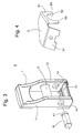
- Fig. 1 shows by way of example a Tragstoffendtagen 6, which is provided for receiving a support means 2, and in which the support means 2 is fixed so that it is held by the Tragstoffendtagen 6.
- the Tragstoffendtagen 6 in this case has a housing 1, which has two side walls 11, 12. At the front, the housing is substantially open.
- the support means 2 is arranged in the housing 1 so that a movable and insertable into the housing wrap 4 comes to rest in the eye of a loop of the suspension element.
- the wrapping element has a recess 41.
- FIG. 2 is a TragstoffendENS shown, in which the wrapping element 4 is now inserted, and is wrapped by an eye of the support means.
- the support means 2 is now held by the frictional force between the surfaces of the support means in the Tragstoffendverbinder.
- the wrapping element 4 can be introduced through an opening 14 through a side wall 11, 12 of the housing 1.
- the wrapping element can now be fixed in its position in the housing and does not slip sideways or slip out of the housing, the fixing element 5 becomes on the lower yoke 13 of the housing attached.
- the fixing element can also be fixed at other locations of the housing, for example on the side wall 11 or 12 of the housing.
- An attachment to the lower yoke 13 is particularly easy to implement, since a surface of the fixing element can be screwed with a bore by means of a screw 55 in the yoke.
- a roller or a pin-shaped element 56 can be attached under the fixing element or between the fixing element and the support means 2.
- the pin-shaped element 56 may be made of metal or of another, non-combustible, in particular non-electrically conductive material. It is clamped when tightening the fixing element 5 between quasi fixing element and support means and thus exerts on the end of the support means pressure. This serves to additionally secure the suspension element 2 in the housing.
- load-bearing tension members melts away, not enough pressure is exerted on the tension members and the frictional force of the support means is no longer sufficient to hold it in Tragstoffendverbinder.
- the roll which is not combustible, is drawn into the gap 15 between the first yoke 13 and the second yoke 17 ( Fig. 5 ).
- the tension members thus experience a pressure and are clamped to the housing by the roller or the pin.
- the gap 15 narrows between the first yoke 13 and the second yoke 17 in the direction of the housing interior.
- the pin or the roller is formed of non-electrically conductive material. If the condition of the tension members is monitored by means of electrical continuity, it must be prevented that an electrical connection via the pin-shaped element is achieved by the pressing of the roller on the strands.
- FIG. 3 shows a Tragstoffend für 6 in a state in which no support means is inserted.
- the Tragstoffend für has a housing 1 with two side walls 11,12, wherein between the side walls, a first wrapping element 3 is attached.
- the second wrapping element 4 can be introduced into the housing 1 through an opening 14 in the side wall 11 or 12. This is usually done after a suspension has already run into the housing and then introduces the second wrap 4 and the bolt in the eye of the support means.
- a sketch of the arrangement is shown on the side surface 11. If the second wrapping element 4 is now inserted into the end connector 6, the recess 41 of the second wrapping element comes to lie within the housing, that is to say between the two side walls 11 and 12. It is advantageous if the depression is indeed within the housing but relatively far at the edge, so near one of the two side walls.
- FIG. 4 shows the fixing element 5, which for fixing the in FIG. 3 and 1 shown second wrap 4 serves.
- the fixing element can be fastened to the housing 1.
- a flat element 57 is proposed for this purpose, which has a bore through which it by means of a screw 55 on the lower yoke 13th the housing 1 of the Tragstoffendverbinders 6 can be attached.
- the attachment to the housing can also be done in other ways.
- the fixing element 5 has a surface 51 which extends parallel to a side wall 11, 12 of the housing in the mounted state.
- the illustrated embodiment is merely an example. The surface may extend on either side of the housing, respectively.
- the fixing element 5 would have two parallel surfaces extending along the side surfaces of the housing. Each of the two surfaces would then engage one of two recesses of the bolt or receive the bolt in one of two recesses.
- the surface 51 has a recess 52.
- the indentation is provided for receiving the belt 4.
- the indentation 52 is dimensioned such that the wrapping element 4 can only be accommodated in it when the walls of the indentation engage in the recess 41 of the wrapping element.
- flank 53, 54 of the recess are pulled down so far that they protrude beyond the center of the belt. This ensures that even if the fixing element 5 is not seated 100 percent, the surface 51 of the fixing element is able to hold the belt 4 in its position.
- the flank 53 is selected in its width so that when inserting the fixing element 5 into the housing 1 for the flank 53 there is just so much space between the yoke and the bolt or wrap element 4 wrapped around the suspension element 2 Fixing element can be placed there. A rotational movement of the entire fixing element, for example, if the surface 57 is no longer screwed tightly to the yoke 13, thus can not immediately lead to a solution of the bolt 4.
- flank would still be close enough to the bolt in the event that the fixing element 5 loosens a little and wobbles, and even intervene in the recess 41 during rotation.
- annular recess in the bolt ensures that the flank always engages.
- a circumferential groove has the further advantage that the bolt must be adjusted only with respect to the lateral alignment. Turning the bolt in the Housing to bring him into a position in which the fixing element can engage is not necessary.
- the small roller or pin 56 which can prevent noise emanating from the suspension element even in the event of a fire, is to be positioned between the fixing element 5 and the suspension element 2, this is shown graphically on the fixing element.
- the special design of the fixing element 5, as in FIG. 4 is merely an example.
- the fixing element can be fastened at arbitrary locations of the housing. It is relevant that it engages in the fastened state in a recess of the bolt 4 and thus protects it from lateral movement.
- a fixation on the side walls is conceivable or a fixing element with a completely different shape and two surfaces which each extend to a side wall of the housing and penetrate there into the depth and hold the wrapper in position.
- the indentation 52 need not be round, as shown, it conforms to the shape of the bolt, and if the bolt has a different shape, the indentation 52 would have a corresponding complementary shape.
- the fixing element could, of course, also be a simple element protruding in the depth, without indentation, which engages in a recess of the bolt 4.
- FIGS. 5, 6 and 7 show the insertion of the support means 2 in a Tragstoffenditati 6.
- the support means 2 is placed in a loop 20. This happens because the end of the support means is guided by a fitter through the opening 16 provided on the housing. Then the support means 2 is bent in the direction of the housing and out through the second opening 15, which is also located at the lower end of the housing between the yoke 13 and the yoke 17, out of the housing. Subsequently, the suspension element or the loop 20 can be placed over the first belt 4. This is in FIG. 6 shown. Around the wrap 4 thus lie two opposite areas of the suspension element. The end of the loop of the support means then forms an eye 23. In the eye 23, the bolt 3 and the second wrapping element can be inserted.
- the support means 2 then only needs to be brought to tension on the side remote from the end by train.
- the support means may in this case be a flat belt, the belt may also have a surface structure, as for example in Figures 1 and 2 is shown. Whether the surface structures of the suspension element lie on top of each other or whether the flat sides of a support belt lie on top of each other is not relevant for the function of the suspension element end connection.
- the strap can thus be introduced in both directions even if its surfaces are designed differently.
Landscapes
- Clamps And Clips (AREA)
Priority Applications (2)
| Application Number | Priority Date | Filing Date | Title |
|---|---|---|---|
| EP09178674A EP2332874A1 (fr) | 2009-12-10 | 2009-12-10 | Serrure à collet dotée d'un élément de fixation |
| US12/902,690 US9004232B2 (en) | 2009-12-10 | 2010-10-12 | Suspension-means end-fastener with fixing element |
Applications Claiming Priority (1)
| Application Number | Priority Date | Filing Date | Title |
|---|---|---|---|
| EP09178674A EP2332874A1 (fr) | 2009-12-10 | 2009-12-10 | Serrure à collet dotée d'un élément de fixation |
Publications (1)
| Publication Number | Publication Date |
|---|---|
| EP2332874A1 true EP2332874A1 (fr) | 2011-06-15 |
Family
ID=42062576
Family Applications (1)
| Application Number | Title | Priority Date | Filing Date |
|---|---|---|---|
| EP09178674A Withdrawn EP2332874A1 (fr) | 2009-12-10 | 2009-12-10 | Serrure à collet dotée d'un élément de fixation |
Country Status (2)
| Country | Link |
|---|---|
| US (1) | US9004232B2 (fr) |
| EP (1) | EP2332874A1 (fr) |
Cited By (1)
| Publication number | Priority date | Publication date | Assignee | Title |
|---|---|---|---|---|
| CN112706114A (zh) * | 2020-11-30 | 2021-04-27 | 中国一冶集团有限公司 | 一种绳体紧固装置 |
Families Citing this family (2)
| Publication number | Priority date | Publication date | Assignee | Title |
|---|---|---|---|---|
| CN108217384B (zh) | 2016-12-14 | 2021-07-06 | 奥的斯电梯公司 | 具有约束的电梯系统悬挂构件端接 |
| US10870557B2 (en) * | 2017-10-12 | 2020-12-22 | Otis Elevator Company | Compact belt termination assembly |
Citations (3)
| Publication number | Priority date | Publication date | Assignee | Title |
|---|---|---|---|---|
| DE1937155A1 (de) * | 1968-06-01 | 1971-02-04 | Sehlbach Herbert Schmalweberei | Vorrichtung zum Verbinden,Spannen,Sichern und Loesen von Verzurrgurten |
| US4365391A (en) * | 1979-07-18 | 1982-12-28 | Chapalain Jean Pierre | Device for locking and adjusting straps for lifting and securing apparatuses |
| EP2000431A1 (fr) * | 2007-06-04 | 2008-12-10 | Inventio Ag | Connection terminale et procédé de fixation d'un moyen de transport de type courroie d'un système d'ascenseur |
Family Cites Families (6)
| Publication number | Priority date | Publication date | Assignee | Title |
|---|---|---|---|---|
| US4493135A (en) * | 1983-03-28 | 1985-01-15 | The Crosby Group, Inc. | Fitting for connection with web-type strapping |
| US6484368B1 (en) * | 2000-01-11 | 2002-11-26 | Otis Elevator Company | Flexible flat tension member termination device |
| ZA200606234B (en) * | 2005-09-02 | 2007-12-27 | Inventio Ag | Suspension means end connector for an elevator |
| CN101506082B (zh) * | 2006-08-29 | 2016-04-27 | 奥蒂斯电梯公司 | 电梯承载终端组件 |
| US8181312B2 (en) * | 2007-06-04 | 2012-05-22 | Inventio Ag | End-connector and method for fastening a flat-belt type suspension means of an elevator system |
| EP2261162A1 (fr) * | 2009-06-10 | 2010-12-15 | Inventio AG | Raccordement d'extrémité de moyen de portage pour une installation d'ascenseur |
-
2009
- 2009-12-10 EP EP09178674A patent/EP2332874A1/fr not_active Withdrawn
-
2010
- 2010-10-12 US US12/902,690 patent/US9004232B2/en active Active
Patent Citations (3)
| Publication number | Priority date | Publication date | Assignee | Title |
|---|---|---|---|---|
| DE1937155A1 (de) * | 1968-06-01 | 1971-02-04 | Sehlbach Herbert Schmalweberei | Vorrichtung zum Verbinden,Spannen,Sichern und Loesen von Verzurrgurten |
| US4365391A (en) * | 1979-07-18 | 1982-12-28 | Chapalain Jean Pierre | Device for locking and adjusting straps for lifting and securing apparatuses |
| EP2000431A1 (fr) * | 2007-06-04 | 2008-12-10 | Inventio Ag | Connection terminale et procédé de fixation d'un moyen de transport de type courroie d'un système d'ascenseur |
Cited By (2)
| Publication number | Priority date | Publication date | Assignee | Title |
|---|---|---|---|---|
| CN112706114A (zh) * | 2020-11-30 | 2021-04-27 | 中国一冶集团有限公司 | 一种绳体紧固装置 |
| CN112706114B (zh) * | 2020-11-30 | 2023-03-14 | 中国一冶集团有限公司 | 一种绳体紧固装置 |
Also Published As
| Publication number | Publication date |
|---|---|
| US9004232B2 (en) | 2015-04-14 |
| US20110139551A1 (en) | 2011-06-16 |
Similar Documents
| Publication | Publication Date | Title |
|---|---|---|
| DE102016208291B4 (de) | Federklammer, Montagewerkzeug sowie Verfahren zum Fixieren von Kontaktpartnern und Verbindungssystem zum Herstellen einer elektrischen und mechanischen Verbindung zwischen Kontaktpartnern | |
| EP2867559A1 (fr) | Dispositif de verrouillage pour une élingue, dispositif de sécurité, dispositif haute pression et procédé de montage du dispositif de sécurité | |
| EP0941901A2 (fr) | Connection entre deux éléments constitutifs | |
| DE102009015288B4 (de) | Halter zum Aufhängen eines Objekts, insbesondere einer Leuchte, an einem Haltemittel | |
| EP2332874A1 (fr) | Serrure à collet dotée d'un élément de fixation | |
| DE102008012020B4 (de) | Seilhalter zum Aufhängen eines Objekts, insbesondere einer Leuchte | |
| DE202007013836U1 (de) | Fadenführer und Fadenliefervorrichtung | |
| DE102011010828B4 (de) | Klemmvorrichtung zur lösbaren Befestigung eines Gerätegehäuses an einer Profilschiene | |
| EP2698336A1 (fr) | Anneau d'arrimage | |
| DE102014103752B3 (de) | Schlosszunge | |
| DE102012007298B4 (de) | Vorrichtung zum höhenverstellbaren Abhängen eines elektrischen Gerätes | |
| DE102006055255B4 (de) | Trägerwerkzeug für eine Schneidplatte und Schneidplatte | |
| DE3340341A1 (de) | Vorrichtung zur kraftentlastung von leitungen | |
| DE102013004326A1 (de) | Vorrichtung zum Bilden von mindestens einer Seilschlinge und Sicherungsvorrichtung | |
| EP1760027B1 (fr) | Dispositif de fin pour élément de suspension d'ascenseur | |
| DE19844211C2 (de) | Verbindung zwischen zwei Bauteilen | |
| DE10113342C1 (de) | Gurtbandbefestigung an einer Gurtaufrollerwelle | |
| AT9304U1 (de) | Leiteranschlussklemme und elektrische steckvorrichtung | |
| EP4007080A1 (fr) | Borne de luminaire pourvue de douille de fermeture | |
| EP3889461A1 (fr) | Liaison d'extrémité de corde amovible pour cordes en fibre hautement modulaires | |
| DE102016117377A1 (de) | Befestigungsvorrichtung für flexible Zugmittel | |
| DE102014112873A1 (de) | Verbinder zum Halten eines Gegenstandes zwischen zwei Haltekörpern sowie Anordnung mit einem solchen Verbinder | |
| DE202005005548U1 (de) | Mit einer bügelförmigen Drahtschutzfeder versehenes elektrisches Kontaktelement | |
| DE102013113847B4 (de) | Halter zum Befestigen eines Objektes an einem Seil | |
| EP2676041B1 (fr) | Douille de suspension de charge et de fixation pour fixer une charge sur un élément porteur |
Legal Events
| Date | Code | Title | Description |
|---|---|---|---|
| PUAI | Public reference made under article 153(3) epc to a published international application that has entered the european phase |
Free format text: ORIGINAL CODE: 0009012 |
|
| AK | Designated contracting states |
Kind code of ref document: A1 Designated state(s): AT BE BG CH CY CZ DE DK EE ES FI FR GB GR HR HU IE IS IT LI LT LU LV MC MK MT NL NO PL PT RO SE SI SK SM TR |
|
| AX | Request for extension of the european patent |
Extension state: AL BA RS |
|
| STAA | Information on the status of an ep patent application or granted ep patent |
Free format text: STATUS: THE APPLICATION IS DEEMED TO BE WITHDRAWN |
|
| 18D | Application deemed to be withdrawn |
Effective date: 20111216 |