EP2345782A1 - Cylindre anti-panique - Google Patents
Cylindre anti-panique Download PDFInfo
- Publication number
- EP2345782A1 EP2345782A1 EP10014493A EP10014493A EP2345782A1 EP 2345782 A1 EP2345782 A1 EP 2345782A1 EP 10014493 A EP10014493 A EP 10014493A EP 10014493 A EP10014493 A EP 10014493A EP 2345782 A1 EP2345782 A1 EP 2345782A1
- Authority
- EP
- European Patent Office
- Prior art keywords
- cylinder
- panic
- sleeve
- locking lug
- core
- Prior art date
- Legal status (The legal status is an assumption and is not a legal conclusion. Google has not performed a legal analysis and makes no representation as to the accuracy of the status listed.)
- Granted
Links
Images

Classifications
-
- E—FIXED CONSTRUCTIONS
- E05—LOCKS; KEYS; WINDOW OR DOOR FITTINGS; SAFES
- E05B—LOCKS; ACCESSORIES THEREFOR; HANDCUFFS
- E05B17/00—Accessories in connection with locks
- E05B17/04—Devices for coupling the turning cylinder of a single or a double cylinder lock with the bolt operating member
- E05B17/047—Devices for coupling the turning cylinder of a single or a double cylinder lock with the bolt operating member with rotating output elements forming part of cylinder locks, e.g. locking cams of double cylinder locks
-
- E—FIXED CONSTRUCTIONS
- E05—LOCKS; KEYS; WINDOW OR DOOR FITTINGS; SAFES
- E05B—LOCKS; ACCESSORIES THEREFOR; HANDCUFFS
- E05B65/00—Locks or fastenings for special use
- E05B65/10—Locks or fastenings for special use for panic or emergency doors
- E05B65/1086—Locks with panic function, e.g. allowing opening from the inside without a ley even when locked from the outside
Definitions
- the invention relates to a digital anti-panic cylinder with a cylinder housing, a cylinder housing received, rotatably mounted in the cylinder housing cylinder core, a rotatably arranged locking lug, a connecting in the presence of the lock authorization the cylinder core with the locking lug coupling, and a closing lug when not in operation Anti-panic cylinder in a predetermined position adjusting return mechanism.
- Self-locking anti-panic locks are known as key-operated variants equipped with a mechanical locking cylinder and as electronic variants equipped with a digital locking cylinder. They have in common that the equipped with these locking systems doors from the outside - as is well known - can only be opened with a key or by transmitting a digital access authorization, whereas the door from the inside can be opened at any time by pressing the door handle and again automatically locked as soon as the door has fallen back into the lock.
- the locking lug also called closing cam or driver
- the locking lug is arranged in non-actuation of the lock cylinder in a position in which the locking lug the anti-panic Function of the lock can not block.
- Such a reset device for the locking lug digital anti-panic locking systems is for example from the DE 10 2004 048 231 B4 known.
- a spring arranged in the knob of a return device designed as a half-cylinder acts on the closing nose via a helically wound element connected to a guide element such that the closing nose is turned back into a rest position after actuation of a digital locking cylinder combined with the return device, also in the form of a half-cylinder the anti-panic function of the lock is not obstructed or even blocked.
- Object of the present invention is therefore to provide an anti-panic cylinder, which is protected from manipulation from the outside, preferably easy to manufacture and install and is particularly preferably closed on both sides.
- the anti-panic cylinder having the features of claim 1.
- the subclaims reflect advantageous embodiments of the invention.
- the basic idea of the invention is to arrange the return mechanism in the cylinder housing of a digital anti-panic closing latch so that the cylinder core can be largely kept free of the components of the return mechanism acting on the closing nose. So it is possible to produce a digital half-cylinder with integrated lock-reset mechanism.
- a simple manufacture, installation and a compact structure with improved protection against manipulation is achieved.
- the inventive design of the digital anti-panic lock cylinder allows in a configuration as a double cylinder lockability of a equipped with the anti-panic invention lock from both sides of a door.
- Fig. 1 shows a schematic sectional view of a portion of the digital anti-panic cylinder according to the invention.
- the digital anti-panic cylinder 10 has a cylinder housing 20 and a cylinder housing 30 rotatably mounted in the cylinder housing.
- An arranged in the cylinder core 30 closing electronics 100 is used to query or for receiving and / or processing a digital Sch.berecht Trent signal by coupling the cylinder core 30 with the locking lug 40th
- the return mechanism ensuring the anti-panic function is formed from the sleeve 50 surrounding the cylinder core 30 and the actuating element 60 which acts on the sleeve 50 and is acted upon by the force of a spring 70.
- a single spring 70 or at least two serially arranged springs can be used with different spring force whose working range is associated with a specific angular position of the locking lug.
- the sleeve 50 is received by the cylinder housing 20 and rotatably mounted in this. It is connected with its one side with the locking lug 40, so that rotation of the sleeve 50 inevitably leads to a rotation of the locking lug 40.
- the actuator 60 is also received by the cylinder housing 20, but slidably mounted in this manner that the actuator 60 acts through the force acting directly on the actuator 60 force of the spring 70 on the sleeve 50 so that by relaxing the spring 70 a position of the sleeve 50 is enforced, wherein the locking lug 40 is arranged in a preferred lower position.
- This position can also be a predefined area in which the locking lug 40 is brought to its rest position.
- the actuator 60 is slidably disposed in the axial direction of the sleeve 50 with respect to the longitudinal axis of the cylinder. In contrast to a set perpendicular to the cylinder axis displaceability of the actuator 60 is set up for a set in the axial direction of the actuator 60 more space, so more spring can be held by a greater spring length for moving the locking lug 50 in the rest position.
- the sleeve 50 - as in Fig. 1 shown - an obliquely about the longitudinal axis of the sleeve 50 extending groove 80 into which the actuator 60 engages. It is understood that the connection of sleeve 50 and locking lug 40 must be made such that the rest position of the locking lug 40 is reached at maximum relaxed spring 70 and the groove 80 must be introduced into the outer wall of the sleeve 50 such that the actuator 60 is securely guided in the groove 80 and can not jump out of this.
- the use of a displaceably arranged in the axial direction of the cylinder 10 spring-loaded actuating element 60 in the direction of the locking lug 40 is possible in principle.
- the in Fig. 1 illustrated embodiment of the inventive anti-panic cylinder 10 are further improved when the spring 70, the actuator 60 is not acted upon in the direction of the locking lug 40 with the spring force, but actuator 60 and spring 70 are arranged vice versa, so that the spring force away from the locking lug 40 acts on the actuator 60.
- no forces acting laterally on the closing lug 40 occur in the resting state, as a result of which the wear of the cylinder components can be reduced.
- the actuating element 60 is formed from a base body and a receptacle occupied by an ellipsoid, wherein the Ellipsoid acts on the actuator 60 (in Fig. 1 indicated).
- the ellipsoid is rotatably mounted in the receptacle, which is preferably made with a clearance, that is to say a movement clearance.
- the ellipsoid is formed as a ball, but may also have other shapes.
- the digital anti-panic cylinder 10 according to the invention can be designed as a half-cylinder or preferably also as a double cylinder which can be closed from both sides.
- the digital anti-panic cylinder 10 according to the invention is designed as a half-cylinder, no further return mechanism made, for example, as a half-cylinder is required.
- the digital anti-panic cylinder 10 according to the invention is designed as a double cylinder that can be closed from both sides, it is advantageous for safety reasons to form the cylinder housing of the anti-panic cylinder in one piece and thus to make it more difficult to destroy the cylinder according to the invention installed in a door , It also makes it possible to move the part of the cylinder (often the knob), which has the closing electronics, on the inside of a door and thus make modifications from the outside inaccessible.
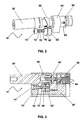
- Fig. 2 shows a perspective view of an anti-panic cylinder according to a second embodiment without a cylinder housing, whereas the installation situation of this anti-panic cylinder in the cylinder housing in longitudinal section in Fig. 3 is shown.
- the in the Fig. 2 and Fig. 3 shown anti-panic cylinder 10 ' has - as well as in Fig. 1 shown embodiment - a cylinder housing 20 'and a cylinder housing 20' rotatably mounted in the cylinder core 30 '.
- the anti-panic cylinder 10 ' also has a closing electronics, which has a coupling mechanism 90, with which the cylinder core 30' with the locking lug 40 'can be coupled.
- the cylinder core 30 ' is coupled to the closing nose 40' so that the lock having the anti-panic cylinder 10 'can be opened, for example, by actuating a knob connected to the cylinder core 30'.
- the anti-panic cylinder 10 ' also has a cylinder core 30' surrounding sleeve 50 ', which is received by the cylinder housing 20' and rotatably mounted therein.
- the sleeve 50 ' is also connected with its one side with the locking lug 40', so that rotation of the sleeve 50 'inevitably causes the rotation of the locking lug 40'.
- the anti-panic cylinder 10' also has a on the sleeve 50 'by the force of a spring 70' acting actuator 60 'on.
- this adjusting element 60 ' engages in contrast to the in Fig. 1 embodiment shown not in an introduced into the outer wall of the sleeve groove, but is supported against a on the Sleeve 50 'arranged control edge.
- the control edge of the sleeve 50 ' is most easily formed by obliquely cutting the sleeve.
- the spring 70 ' is preferably mounted against a first abutment 74' and a particularly preferably with the adjusting element 60 'connected to the axis 72' surrounding guide sleeve 76 '.
- the spring 70 ' can be prestressed in the cylinder housing 20' by means of the first abutment 74 '.
- the sleeve 50' on your the locking lug 40 'facing Side preferably provided with a perpendicular to the longitudinal axis of the cylinder core 30 'extending edge against which a bearing member 62' is supported such that the portion of the sleeve 50 'from the control edge to perpendicular to the longitudinal axis of the cylinder core 30' extending edge between the actuator 60th 'and the bearing element 62' is added.
- the bearing element 62 ' is particularly preferably fixed on the axis 72' arranged parallel to the cylinder core 30 '.
- the coupling 90 provided for connecting the cylinder core 30 'to the closing nose 40' has a device for permanently connecting the cylinder core 30 'to the closing nose 40'.
- This device is preferably realized in that the engaging in the locking lug 40 'coupling part by means of a fastener 92 in a first position in which an induced by the closing electronics input and decoupling of the locking lug 40' with the cylinder core 30 'is possible, or in a second position, in which the locking lug 40 'is permanently coupled to the cylinder core 30' is fixed.
- the fastening means 92 may be, for example, a (maggot) screw 92 accessible from outside the cylinder housing 20 'and arranged in a slot, which determines the relative position of the coupling part with respect to the locking lug 40' and the cylinder core 30 ', respectively.
- the spring 94 is preferably connected via a hub with the shaft of a motor which biases the spring 94 and the coupling member moves to the desired position in which the coupling part by means of the fastening means 92 relative to the locking lug 40 'is fixed.
- Both embodiments have the advantage that a designed as a half or double cylinder lock cylinder can be equipped with an anti-panic function, wherein the cylinder core is largely kept free of the components of acting on the locking cam return mechanism.
- a lockability of a equipped with the anti-panic invention cylinder lock from both sides of a door is possible.
Landscapes
- Lock And Its Accessories (AREA)
Applications Claiming Priority (1)
| Application Number | Priority Date | Filing Date | Title |
|---|---|---|---|
| DE102009052663.3A DE102009052663B4 (de) | 2009-11-12 | 2009-11-12 | Anti-Panik-Zylinder |
Publications (2)
| Publication Number | Publication Date |
|---|---|
| EP2345782A1 true EP2345782A1 (fr) | 2011-07-20 |
| EP2345782B1 EP2345782B1 (fr) | 2014-05-07 |
Family
ID=43877526
Family Applications (1)
| Application Number | Title | Priority Date | Filing Date |
|---|---|---|---|
| EP20100014493 Not-in-force EP2345782B1 (fr) | 2009-11-12 | 2010-11-11 | Cylindre anti-panique |
Country Status (2)
| Country | Link |
|---|---|
| EP (1) | EP2345782B1 (fr) |
| DE (1) | DE102009052663B4 (fr) |
Cited By (4)
| Publication number | Priority date | Publication date | Assignee | Title |
|---|---|---|---|---|
| EP2597229A1 (fr) | 2011-11-25 | 2013-05-29 | CEStronics GmbH | Elément d'embrayage, système de boulon, mécanisme de rappel, boîtier de cylindre, dispositif de cylindre, cylindre de fermeture et serrure à mortaiser ainsi que procédé de rappel et de montage associés |
| DE102012108432A1 (de) * | 2012-06-13 | 2013-12-19 | Uhlmann & Zacher Gmbh | Antipanikzylinder |
| DE102013001501B3 (de) | 2013-01-29 | 2014-06-26 | Klaus Meister | Rückstellsystem für die Schließnase elektronischer Schließsysteme |
| DE102014111413B3 (de) * | 2014-08-11 | 2015-09-17 | ASTRA Gesellschaft für Asset Management mbH & Co. KG | Schließzylinderanordnung |
Families Citing this family (1)
| Publication number | Priority date | Publication date | Assignee | Title |
|---|---|---|---|---|
| DE102016211573A1 (de) | 2016-06-28 | 2017-12-28 | Aug. Winkhaus Gmbh & Co. Kg | Schließeinrichtung, insbesondere Schließzylinder |
Citations (3)
| Publication number | Priority date | Publication date | Assignee | Title |
|---|---|---|---|---|
| DE10316522B3 (de) * | 2003-04-10 | 2004-07-08 | Seccor High Security Gmbh | Automatisches Rückstellsystem für elektronische Schließsysteme im Einsatz mit Panikschlössern |
| DE102004048231B4 (de) | 2004-10-04 | 2006-08-03 | Simonsvoss Technologies Ag | Automatische Rückstellvorrichtung |
| DE102006020614A1 (de) * | 2005-04-29 | 2006-11-02 | Mehmet Sancak | Schloss mit automatischer Rückstellung des Schließbarts |
Family Cites Families (2)
| Publication number | Priority date | Publication date | Assignee | Title |
|---|---|---|---|---|
| AT504933B8 (de) * | 2007-02-08 | 2009-05-15 | Evva Werke | Schloss mit selbsttätiger schliessbartrückstellung |
| DE102008056627C5 (de) * | 2008-11-10 | 2012-08-02 | Wilka Schließtechnik GmbH | Profilzylinderschloss mit einstückigem radialem Gehäuseansatz und mit automatischer Rückstellvorrichtung für einen Schließbart oder Mitnehmerkörper |
-
2009
- 2009-11-12 DE DE102009052663.3A patent/DE102009052663B4/de not_active Expired - Fee Related
-
2010
- 2010-11-11 EP EP20100014493 patent/EP2345782B1/fr not_active Not-in-force
Patent Citations (3)
| Publication number | Priority date | Publication date | Assignee | Title |
|---|---|---|---|---|
| DE10316522B3 (de) * | 2003-04-10 | 2004-07-08 | Seccor High Security Gmbh | Automatisches Rückstellsystem für elektronische Schließsysteme im Einsatz mit Panikschlössern |
| DE102004048231B4 (de) | 2004-10-04 | 2006-08-03 | Simonsvoss Technologies Ag | Automatische Rückstellvorrichtung |
| DE102006020614A1 (de) * | 2005-04-29 | 2006-11-02 | Mehmet Sancak | Schloss mit automatischer Rückstellung des Schließbarts |
Cited By (7)
| Publication number | Priority date | Publication date | Assignee | Title |
|---|---|---|---|---|
| EP2597229A1 (fr) | 2011-11-25 | 2013-05-29 | CEStronics GmbH | Elément d'embrayage, système de boulon, mécanisme de rappel, boîtier de cylindre, dispositif de cylindre, cylindre de fermeture et serrure à mortaiser ainsi que procédé de rappel et de montage associés |
| DE102012108432A1 (de) * | 2012-06-13 | 2013-12-19 | Uhlmann & Zacher Gmbh | Antipanikzylinder |
| DE102012108432B4 (de) | 2012-06-13 | 2019-05-09 | Uhlmann & Zacher Gmbh | Antipanikzylinder |
| DE102013001501B3 (de) | 2013-01-29 | 2014-06-26 | Klaus Meister | Rückstellsystem für die Schließnase elektronischer Schließsysteme |
| DE102013001501C5 (de) * | 2013-01-29 | 2017-03-16 | Klaus Meister | Rückstellsystem für die Schließnase elektronischer Schließsysteme |
| DE102014111413B3 (de) * | 2014-08-11 | 2015-09-17 | ASTRA Gesellschaft für Asset Management mbH & Co. KG | Schließzylinderanordnung |
| EP2985398A1 (fr) | 2014-08-11 | 2016-02-17 | ASTRA Gesellschaft für Asset Management mbH & Co. KG | Systeme de cylindre de fermeture |
Also Published As
| Publication number | Publication date |
|---|---|
| DE102009052663B4 (de) | 2016-11-10 |
| DE102009052663A1 (de) | 2011-05-19 |
| EP2345782B1 (fr) | 2014-05-07 |
Similar Documents
| Publication | Publication Date | Title |
|---|---|---|
| EP1636454B1 (fr) | Barillet electromagnetique | |
| EP2525025B1 (fr) | Unité électronique pour un dispositif de verrouillage et système de fermeture | |
| EP3207197B1 (fr) | Élément d'actionnement pour une serrure à palastre | |
| EP2473690B2 (fr) | Dispositif de verrouillage | |
| DE102018202563B4 (de) | Knauf für einen elektronischen Schließzylinder | |
| EP2391786B1 (fr) | Boîtier de sécurité | |
| EP2105556A1 (fr) | Dispositif de verrouillage | |
| EP2927395B1 (fr) | Système de couplage pour un cylindre de serrure à double ressort de compression | |
| DE102008063061A1 (de) | Betätigungsvorrichtung für ein elektronisches Türschloß | |
| EP2345782B1 (fr) | Cylindre anti-panique | |
| EP1719861B1 (fr) | Serrure cylindrique pour un système de verrouillage électronique | |
| DE19604442A1 (de) | Sicherheitsvorrichtung für elektronische Schlösser | |
| EP2439361B1 (fr) | Dispositif de fermeture, notamment pour portes | |
| DE102007011554B4 (de) | Koppeleinheit für elektronische Schließ-Systeme | |
| EP2927396B1 (fr) | Système de couplage pour barillet de serrure doté d'un ressort | |
| DE10225649B4 (de) | Ferngesteuert freigebbarer Schließzylinder | |
| EP1662076B1 (fr) | Dispositif d'accouplement pour un dispositif de verrouillage | |
| EP2136019B1 (fr) | Sous-assemble pour le blocage ou la libération d'une serrure de porte | |
| EP3502380B1 (fr) | Dispositif de fixation d'un ouvre-porte | |
| EP4372190B1 (fr) | Unité de fermeture électronique | |
| DE102019113666A1 (de) | Schließzylinder | |
| EP1671001B1 (fr) | Serrure | |
| EP4191002A1 (fr) | Dispositif d'arrêt pour un élément de fermeture ou un élément de commutation | |
| DE102014110970B3 (de) | Schließzylinderanordnung | |
| EP4086414B1 (fr) | Agencement de cylindre de fermeture pourvu d'accouplement à poignée |
Legal Events
| Date | Code | Title | Description |
|---|---|---|---|
| PUAI | Public reference made under article 153(3) epc to a published international application that has entered the european phase |
Free format text: ORIGINAL CODE: 0009012 |
|
| AK | Designated contracting states |
Kind code of ref document: A1 Designated state(s): AL AT BE BG CH CY CZ DE DK EE ES FI FR GB GR HR HU IE IS IT LI LT LU LV MC MK MT NL NO PL PT RO RS SE SI SK SM TR |
|
| AX | Request for extension of the european patent |
Extension state: BA ME |
|
| 17P | Request for examination filed |
Effective date: 20110913 |
|
| GRAP | Despatch of communication of intention to grant a patent |
Free format text: ORIGINAL CODE: EPIDOSNIGR1 |
|
| RIC1 | Information provided on ipc code assigned before grant |
Ipc: E05B 65/10 20060101ALI20131216BHEP Ipc: E05B 17/04 20060101AFI20131216BHEP |
|
| INTG | Intention to grant announced |
Effective date: 20140116 |
|
| GRAS | Grant fee paid |
Free format text: ORIGINAL CODE: EPIDOSNIGR3 |
|
| GRAP | Despatch of communication of intention to grant a patent |
Free format text: ORIGINAL CODE: EPIDOSNIGR1 |
|
| GRAA | (expected) grant |
Free format text: ORIGINAL CODE: 0009210 |
|
| INTG | Intention to grant announced |
Effective date: 20140326 |
|
| AK | Designated contracting states |
Kind code of ref document: B1 Designated state(s): AL AT BE BG CH CY CZ DE DK EE ES FI FR GB GR HR HU IE IS IT LI LT LU LV MC MK MT NL NO PL PT RO RS SE SI SK SM TR |
|
| REG | Reference to a national code |
Ref country code: GB Ref legal event code: FG4D Free format text: NOT ENGLISH |
|
| REG | Reference to a national code |
Ref country code: AT Ref legal event code: REF Ref document number: 666852 Country of ref document: AT Kind code of ref document: T Effective date: 20140515 |
|
| REG | Reference to a national code |
Ref country code: IE Ref legal event code: FG4D Free format text: LANGUAGE OF EP DOCUMENT: GERMAN |
|
| REG | Reference to a national code |
Ref country code: DE Ref legal event code: R096 Ref document number: 502010006864 Country of ref document: DE Effective date: 20140618 |
|
| REG | Reference to a national code |
Ref country code: NL Ref legal event code: VDEP Effective date: 20140507 |
|
| REG | Reference to a national code |
Ref country code: LT Ref legal event code: MG4D |
|
| PG25 | Lapsed in a contracting state [announced via postgrant information from national office to epo] |
Ref country code: GR Free format text: LAPSE BECAUSE OF FAILURE TO SUBMIT A TRANSLATION OF THE DESCRIPTION OR TO PAY THE FEE WITHIN THE PRESCRIBED TIME-LIMIT Effective date: 20140808 Ref country code: LT Free format text: LAPSE BECAUSE OF FAILURE TO SUBMIT A TRANSLATION OF THE DESCRIPTION OR TO PAY THE FEE WITHIN THE PRESCRIBED TIME-LIMIT Effective date: 20140507 Ref country code: FI Free format text: LAPSE BECAUSE OF FAILURE TO SUBMIT A TRANSLATION OF THE DESCRIPTION OR TO PAY THE FEE WITHIN THE PRESCRIBED TIME-LIMIT Effective date: 20140507 Ref country code: NO Free format text: LAPSE BECAUSE OF FAILURE TO SUBMIT A TRANSLATION OF THE DESCRIPTION OR TO PAY THE FEE WITHIN THE PRESCRIBED TIME-LIMIT Effective date: 20140807 Ref country code: CY Free format text: LAPSE BECAUSE OF FAILURE TO SUBMIT A TRANSLATION OF THE DESCRIPTION OR TO PAY THE FEE WITHIN THE PRESCRIBED TIME-LIMIT Effective date: 20140507 Ref country code: IS Free format text: LAPSE BECAUSE OF FAILURE TO SUBMIT A TRANSLATION OF THE DESCRIPTION OR TO PAY THE FEE WITHIN THE PRESCRIBED TIME-LIMIT Effective date: 20140907 |
|
| PG25 | Lapsed in a contracting state [announced via postgrant information from national office to epo] |
Ref country code: RS Free format text: LAPSE BECAUSE OF FAILURE TO SUBMIT A TRANSLATION OF THE DESCRIPTION OR TO PAY THE FEE WITHIN THE PRESCRIBED TIME-LIMIT Effective date: 20140507 Ref country code: LV Free format text: LAPSE BECAUSE OF FAILURE TO SUBMIT A TRANSLATION OF THE DESCRIPTION OR TO PAY THE FEE WITHIN THE PRESCRIBED TIME-LIMIT Effective date: 20140507 Ref country code: ES Free format text: LAPSE BECAUSE OF FAILURE TO SUBMIT A TRANSLATION OF THE DESCRIPTION OR TO PAY THE FEE WITHIN THE PRESCRIBED TIME-LIMIT Effective date: 20140507 Ref country code: HR Free format text: LAPSE BECAUSE OF FAILURE TO SUBMIT A TRANSLATION OF THE DESCRIPTION OR TO PAY THE FEE WITHIN THE PRESCRIBED TIME-LIMIT Effective date: 20140507 Ref country code: PL Free format text: LAPSE BECAUSE OF FAILURE TO SUBMIT A TRANSLATION OF THE DESCRIPTION OR TO PAY THE FEE WITHIN THE PRESCRIBED TIME-LIMIT Effective date: 20140507 Ref country code: SE Free format text: LAPSE BECAUSE OF FAILURE TO SUBMIT A TRANSLATION OF THE DESCRIPTION OR TO PAY THE FEE WITHIN THE PRESCRIBED TIME-LIMIT Effective date: 20140507 |
|
| PG25 | Lapsed in a contracting state [announced via postgrant information from national office to epo] |
Ref country code: PT Free format text: LAPSE BECAUSE OF FAILURE TO SUBMIT A TRANSLATION OF THE DESCRIPTION OR TO PAY THE FEE WITHIN THE PRESCRIBED TIME-LIMIT Effective date: 20140908 |
|
| PG25 | Lapsed in a contracting state [announced via postgrant information from national office to epo] |
Ref country code: EE Free format text: LAPSE BECAUSE OF FAILURE TO SUBMIT A TRANSLATION OF THE DESCRIPTION OR TO PAY THE FEE WITHIN THE PRESCRIBED TIME-LIMIT Effective date: 20140507 Ref country code: DK Free format text: LAPSE BECAUSE OF FAILURE TO SUBMIT A TRANSLATION OF THE DESCRIPTION OR TO PAY THE FEE WITHIN THE PRESCRIBED TIME-LIMIT Effective date: 20140507 Ref country code: RO Free format text: LAPSE BECAUSE OF FAILURE TO SUBMIT A TRANSLATION OF THE DESCRIPTION OR TO PAY THE FEE WITHIN THE PRESCRIBED TIME-LIMIT Effective date: 20140507 Ref country code: CZ Free format text: LAPSE BECAUSE OF FAILURE TO SUBMIT A TRANSLATION OF THE DESCRIPTION OR TO PAY THE FEE WITHIN THE PRESCRIBED TIME-LIMIT Effective date: 20140507 Ref country code: SK Free format text: LAPSE BECAUSE OF FAILURE TO SUBMIT A TRANSLATION OF THE DESCRIPTION OR TO PAY THE FEE WITHIN THE PRESCRIBED TIME-LIMIT Effective date: 20140507 |
|
| REG | Reference to a national code |
Ref country code: DE Ref legal event code: R097 Ref document number: 502010006864 Country of ref document: DE |
|
| PG25 | Lapsed in a contracting state [announced via postgrant information from national office to epo] |
Ref country code: NL Free format text: LAPSE BECAUSE OF FAILURE TO SUBMIT A TRANSLATION OF THE DESCRIPTION OR TO PAY THE FEE WITHIN THE PRESCRIBED TIME-LIMIT Effective date: 20140507 |
|
| PLBE | No opposition filed within time limit |
Free format text: ORIGINAL CODE: 0009261 |
|
| STAA | Information on the status of an ep patent application or granted ep patent |
Free format text: STATUS: NO OPPOSITION FILED WITHIN TIME LIMIT |
|
| 26N | No opposition filed |
Effective date: 20150210 |
|
| PG25 | Lapsed in a contracting state [announced via postgrant information from national office to epo] |
Ref country code: IT Free format text: LAPSE BECAUSE OF FAILURE TO SUBMIT A TRANSLATION OF THE DESCRIPTION OR TO PAY THE FEE WITHIN THE PRESCRIBED TIME-LIMIT Effective date: 20140507 |
|
| REG | Reference to a national code |
Ref country code: DE Ref legal event code: R097 Ref document number: 502010006864 Country of ref document: DE Effective date: 20150210 |
|
| REG | Reference to a national code |
Ref country code: DE Ref legal event code: R119 Ref document number: 502010006864 Country of ref document: DE |
|
| PG25 | Lapsed in a contracting state [announced via postgrant information from national office to epo] |
Ref country code: BE Free format text: LAPSE BECAUSE OF NON-PAYMENT OF DUE FEES Effective date: 20141130 Ref country code: MC Free format text: LAPSE BECAUSE OF FAILURE TO SUBMIT A TRANSLATION OF THE DESCRIPTION OR TO PAY THE FEE WITHIN THE PRESCRIBED TIME-LIMIT Effective date: 20140507 Ref country code: LU Free format text: LAPSE BECAUSE OF FAILURE TO SUBMIT A TRANSLATION OF THE DESCRIPTION OR TO PAY THE FEE WITHIN THE PRESCRIBED TIME-LIMIT Effective date: 20141111 |
|
| REG | Reference to a national code |
Ref country code: CH Ref legal event code: PL |
|
| GBPC | Gb: european patent ceased through non-payment of renewal fee |
Effective date: 20141111 |
|
| PG25 | Lapsed in a contracting state [announced via postgrant information from national office to epo] |
Ref country code: SI Free format text: LAPSE BECAUSE OF FAILURE TO SUBMIT A TRANSLATION OF THE DESCRIPTION OR TO PAY THE FEE WITHIN THE PRESCRIBED TIME-LIMIT Effective date: 20140507 Ref country code: CH Free format text: LAPSE BECAUSE OF NON-PAYMENT OF DUE FEES Effective date: 20141130 Ref country code: LI Free format text: LAPSE BECAUSE OF NON-PAYMENT OF DUE FEES Effective date: 20141130 |
|
| REG | Reference to a national code |
Ref country code: IE Ref legal event code: MM4A |
|
| REG | Reference to a national code |
Ref country code: FR Ref legal event code: ST Effective date: 20150731 |
|
| PG25 | Lapsed in a contracting state [announced via postgrant information from national office to epo] |
Ref country code: DE Free format text: LAPSE BECAUSE OF NON-PAYMENT OF DUE FEES Effective date: 20150602 Ref country code: GB Free format text: LAPSE BECAUSE OF NON-PAYMENT OF DUE FEES Effective date: 20141111 Ref country code: IE Free format text: LAPSE BECAUSE OF NON-PAYMENT OF DUE FEES Effective date: 20141111 |
|
| PG25 | Lapsed in a contracting state [announced via postgrant information from national office to epo] |
Ref country code: FR Free format text: LAPSE BECAUSE OF NON-PAYMENT OF DUE FEES Effective date: 20141201 |
|
| PG25 | Lapsed in a contracting state [announced via postgrant information from national office to epo] |
Ref country code: SM Free format text: LAPSE BECAUSE OF FAILURE TO SUBMIT A TRANSLATION OF THE DESCRIPTION OR TO PAY THE FEE WITHIN THE PRESCRIBED TIME-LIMIT Effective date: 20140507 |
|
| PG25 | Lapsed in a contracting state [announced via postgrant information from national office to epo] |
Ref country code: BG Free format text: LAPSE BECAUSE OF FAILURE TO SUBMIT A TRANSLATION OF THE DESCRIPTION OR TO PAY THE FEE WITHIN THE PRESCRIBED TIME-LIMIT Effective date: 20140507 |
|
| PG25 | Lapsed in a contracting state [announced via postgrant information from national office to epo] |
Ref country code: MT Free format text: LAPSE BECAUSE OF FAILURE TO SUBMIT A TRANSLATION OF THE DESCRIPTION OR TO PAY THE FEE WITHIN THE PRESCRIBED TIME-LIMIT Effective date: 20140507 Ref country code: TR Free format text: LAPSE BECAUSE OF FAILURE TO SUBMIT A TRANSLATION OF THE DESCRIPTION OR TO PAY THE FEE WITHIN THE PRESCRIBED TIME-LIMIT Effective date: 20140507 Ref country code: HU Free format text: LAPSE BECAUSE OF FAILURE TO SUBMIT A TRANSLATION OF THE DESCRIPTION OR TO PAY THE FEE WITHIN THE PRESCRIBED TIME-LIMIT; INVALID AB INITIO Effective date: 20101111 |
|
| REG | Reference to a national code |
Ref country code: AT Ref legal event code: MM01 Ref document number: 666852 Country of ref document: AT Kind code of ref document: T Effective date: 20151111 |
|
| PG25 | Lapsed in a contracting state [announced via postgrant information from national office to epo] |
Ref country code: AT Free format text: LAPSE BECAUSE OF NON-PAYMENT OF DUE FEES Effective date: 20151111 |
|
| PG25 | Lapsed in a contracting state [announced via postgrant information from national office to epo] |
Ref country code: MK Free format text: LAPSE BECAUSE OF FAILURE TO SUBMIT A TRANSLATION OF THE DESCRIPTION OR TO PAY THE FEE WITHIN THE PRESCRIBED TIME-LIMIT Effective date: 20140507 |
|
| PG25 | Lapsed in a contracting state [announced via postgrant information from national office to epo] |
Ref country code: AL Free format text: LAPSE BECAUSE OF FAILURE TO SUBMIT A TRANSLATION OF THE DESCRIPTION OR TO PAY THE FEE WITHIN THE PRESCRIBED TIME-LIMIT Effective date: 20140507 |