EP2348824B1 - Vorrichtung zur behandlung von tieren mit einer schale, auf die die tiere auftreten können - Google Patents
Vorrichtung zur behandlung von tieren mit einer schale, auf die die tiere auftreten können Download PDFInfo
- Publication number
- EP2348824B1 EP2348824B1 EP09747932.3A EP09747932A EP2348824B1 EP 2348824 B1 EP2348824 B1 EP 2348824B1 EP 09747932 A EP09747932 A EP 09747932A EP 2348824 B1 EP2348824 B1 EP 2348824B1
- Authority
- EP
- European Patent Office
- Prior art keywords
- tray
- treatment
- liquid
- filling
- treatment device
- Prior art date
- Legal status (The legal status is an assumption and is not a legal conclusion. Google has not performed a legal analysis and makes no representation as to the accuracy of the status listed.)
- Active
Links
Images


Classifications
-
- A—HUMAN NECESSITIES
- A01—AGRICULTURE; FORESTRY; ANIMAL HUSBANDRY; HUNTING; TRAPPING; FISHING
- A01K—ANIMAL HUSBANDRY; AVICULTURE; APICULTURE; PISCICULTURE; FISHING; REARING OR BREEDING ANIMALS, NOT OTHERWISE PROVIDED FOR; NEW BREEDS OF ANIMALS
- A01K13/00—Devices for grooming or caring of animals, e.g. curry-combs; Fetlock rings; Tail-holders; Devices for preventing crib-biting; Washing devices; Protection against weather conditions or insects
- A01K13/003—Devices for applying insecticides or medication
-
- A—HUMAN NECESSITIES
- A61—MEDICAL OR VETERINARY SCIENCE; HYGIENE
- A61D—VETERINARY INSTRUMENTS, IMPLEMENTS, TOOLS, OR METHODS
- A61D11/00—Washing devices or gaseous curative baths specially adapted to veterinary purposes
Definitions
- the invention relates to a device for performing a cleaning and/or disinfecting treatment on body parts of animals, comprising a treatment zone which is adapted to receive the animals to be treated; means for guiding the animals through the treatment zone in a defined walking direction; and a treatment tray which is suitable for containing a quantity of cleaning and/or disinfecting liquid, which is located at ground level in the treatment zone, in a horizontal operational position, and which is therefore suitable to be trod upon by the animals.
- a cleaning and/or disinfecting treatment can be performed on claws of cows, for example. This is particularly of importance in so-called walking stables, in which the cows walk a fixed route, usually twice a day, in order to reach a place where a milking machine and food are present. While walking, the cows come into contact with their own manure and the manure of other cows, as a result of which the cows catch disorders of the claws, such as sores, Mortellaro or foot-rot. These disorders can be prevented by regularly cleaning and disinfecting the claws.
- a device for cleaning and disinfecting claws of cows is known from Dutch patent 1 009 895 .
- the known device comprises a tray on which a cow places her legs when she takes place in the device.
- a spraying system is present, which comprises sprayers for spraying the back legs of the cow with a cleaning liquid and a disinfecting liquid.
- sprayers for spraying the back legs of the cow with a cleaning liquid and a disinfecting liquid.
- a first important disadvantage is that the dirt ends up behind the tray, as a result of which a cow comes directly into contact with the dirt of previous cows after she has been treated in the device.
- a second important disadvantage is that cleaning of the tray takes a rather long time, which can not be used for receiving and treating a cow.
- GB-A-2311202 discloses an elongate trough with low end walls and higher side walls for animals to walk through from one end to the other end.
- This objective is achieved by a device according to claim 1.
- the treatment tray has a tiltable arrangement.
- Such an arrangement allows for a very quick emptying of the treatment tray, as the liquid which is present in the tray immediately pours out of the tray when the tray is tilted.
- the means for tilting the treatment tray are adapted to tilt the tray in such a way that the liquid flows to an area which is located outside of areas which are located in front of the device and behind the device as seen in the walking direction. In this way, it is guaranteed that the discharged liquid cannot reach the areas where the animals are walking when they are entering and/or exiting the treatment device. Hence, the risk of contamination is as low as possible.
- the treatment tray is tiltable such as to discharge liquid at a side of the device.
- a tiltably arranged tray is known from European patent application 1 099 373 , but this tray is not suitable for realizing a direct discharge of liquid outside of the device. Instead, in the known construction, the liquid is pumped from the tray when the tray is in an almost vertical position. Furthermore, the tray is tilted around a tilting axis extending perpendicular to the walking direction, so that if a direct discharge would take place from the tray, this discharge would be to the front or the back of the device.
- the treatment tray is tiltable such as to discharge liquid outside of a walking path of the animals is an important aspect of the invention.
- the treatment tray is tiltable around a tilting axis extending substantially in the walking direction.
- contamination of the walking path is prevented. An animal may safely walk to and from the device without the risk of contacting manure or other dirt.
- the tilting means are adapted to put the treatment tray from the horizontal operational position, i.e. the position for receiving the animals, to a vertical or close to vertical position in which the treatment tray is not in use.
- the tilting means On the basis of this function of the tilting means, a possibility of getting the treatment tray practically out of the walking path is created, which is advantageous in view of cleaning and maintenance.
- the device according to the invention is equipped with a frame, which plays a role in guiding the animals through the device in a correct manner, and which serves for supporting various components of the device.
- a frame which plays a role in guiding the animals through the device in a correct manner, and which serves for supporting various components of the device.
- the treatment tray is connected to the frame through at least one bar which is arranged such as to be retractable and extendable.
- the treatment tray it is practical for the treatment tray to be rectangular, wherein the bar is pivotably attached to a side of the tray extending in the walking direction. In such a case, when the length of the bar is varied, it is achieved that the tray tilts about its opposite side which remains on ground level during the tilting process, due to gravity.
- the device according to the invention comprises at least two supply systems, wherein each supply system has a reservoir for containing a quantity of disinfecting agent, a conduit for supplying disinfecting agent to the treatment tray, and a pump for displacing disinfecting agent from the reservoir to the treatment tray, through the conduit.
- the device according to the invention further comprises a filling tray which is arranged at a higher level in the device than the treatment tray in the operational position, and which is suitable to contain a quantity of liquid, wherein a conduit is provided for transporting liquid from the filling tray to the treatment tray in the operational position.
- a filling tray as mentioned can be used for guaranteeing a quick filling process of the treatment tray. In the process, a pump is not required, as a transport of liquid from the filling tray to the treatment tray can be performed on the basis of gravity.
- the conduit for transporting liquid from the filling tray to the treatment tray may be a tube having a suitable diameter. When the device has a frame as mentioned earlier, the tube may be integrated in the frame.
- the filling tray is only used for containing water and supplying water to the treatment tray, as in that case, a potentially dangerous situation in which hazardous agents are present at a level which is considerably higher than ground level is avoided.
- this may be done by transporting a first quantity of water from the filling tray to the treatment tray, adding the disinfecting agent by activating an appropriate supply system, and transporting a second quantity of water from the filling tray to the treatment tray, so that an effective mixing of the disinfecting agent and the water is automatically obtained, and there is no need for additional mixing means.
- the device in order to prevent a constant flow of liquid from the filling tray to the treatment tray, the device comprises means which are suitable to allow a connection of the filling tray to the conduit for transporting the liquid to the treatment tray to be open in a first position, and to close said connection in a second position.
- means are provided for automatically controlling the opening/closing means, wherein such means are programmed such as to avoid unnecessary spillage of liquid.
- the filling tray may be provided with means for connecting the tray to a conduit for supplying liquid to the tray, wherein opening/closing means may furthermore be provided for controlling a filling process of the tray.
- the opening/closing means may comprise a suitable float mechanism, which is capable of only allowing a supply of liquid when a liquid level in the tray is below a certain maximum level, and automatically shutting off the supply as soon as the maximum level appears to be reached.
- the float mechanism is capable of operating the opening/closing means depending on the liquid level in the filling tray.
- the device in order for the device to work automatically, it is advantageous if the device is equipped with means for controlling various components of the device according to predetermined routines, wherein means for detecting relevant parameters are also provided and coupled to the controlling means.
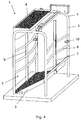
- FIG. 1 An embodiment of a device according to the invention for performing a cleaning and/or disinfecting treatment on claws of cows is shown in the figures, and is indicated in general by reference numeral 1.
- the treatment device 1 comprises a treatment zone 2 where a treatment tray 3, i.e. a shallow tray 3 which is arranged at ground level in a normal, operational position of the tray 3 as shown in figures 1 and 2 is present.
- the treatment tray 3 serves for containing a quantity of liquid having cleaning and/or disinfecting properties.
- a cow is supposed to walk to the treatment zone 2 and step inside the treatment tray 3, so that her claws are immersed in the liquid, and the cleaning and/or disinfecting treatment can actually take place.
- liquid is indicated as a dark-coloured mass.
- the treatment tray 3 has a rectangular shape, which does not alter the fact that other suitable shapes are also possible within the scope of the invention.
- the treatment device 1 comprises a frame 4 having standing supporting bars 5 and more or less horizontal bars 6 for guiding a cow during her walk through the device 1.
- the frame 4 is designed such as to be open at sides which are a front side and a back side as seen in a walking direction of a cow through the device 1, whereas the horizontal bars 6 serve for closing the sides.
- the openings at the front side and the back side of the frame 4 are large enough for allowing a cow to pass.
- the frame 4 constitutes a kind of tunnel in which it is not possible for a cow to turn, so that she is naturally guided through the frame 4 in the walking direction once she has entered the device 1.
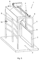
- the telescopic bar 7 is extendible and retractable in a substantially vertical direction, wherein an end of the bar 7 is pivotably connected to a side of the treatment tray 3 extending in the walking direction, at a more or less central position.
- the side as mentioned is pulled upward when the telescopic bar 7 is retracted, so that the tray 3 is tilted, wherein an opposite side of the tray 3 remains on ground level, due to gravity.
- the tilting movement is performed around a tilting axis which is at the position of the side that remains on ground level. During the tilting movement, this tilting axis is pulled toward the side of the frame 4 where the telescopic bar 7 is located.
- Figures 3 and 4 serve to illustrate an arbitrary stage during the tilting movement.
- the liquid that is present inside the treatment tray 3 is discharged from the tray 3, and flows from the treatment zone 2 to outside of the device 1, at a side of the treatment device 1. It is noted that any suitable means may be provided for receiving the discharged liquid at that location.
- a first important advantage of this way of discharging the liquid is that the liquid does not end up in a walking path of the cow, so that contamination is kept to a minimum when the device 1 is applied.
- Another important advantage of this way of discharging the liquid is that the emptying process only takes little time.
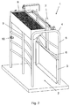
- the telescopic bar 7 can be retracted to such an extent, that the treatment tray 3 is pulled in a more or less vertical position, and is positioned against the bars 5, 6 of the frame 4. In that position, the device 1 is freely accessible without the tray 3 being in the way, which may be handy in a situation of maintenance, for example.
- the stowed-away position of the tray 3 as described is illustrated in figures 5 and 6 .
- the treatment device 1 comprises various components which have a function in filling the treatment tray 3 again after the tray 3 has been emptied.
- the device 1 comprises systems for supplying disinfecting agent to the tray 3.
- the device 1 comprises another tray 8, which will hereinafter be referred to as filling tray 8, and which is intended to be filled with water.
- the filling tray 8 is positioned at a top of the frame 4, such as to be at a considerably higher level than the treatment tray 3.
- the treatment device 1 further comprises a hollow tube 9 extending from the filling tray 8 in a downward direction. This tube 9 serves for transporting water from the filling tray 8 to the treatment tray 3.
- Means for opening and closing a connection between the filling tray 8 and the tube 9 are provided for controlling the supply of water to the treatment tray 3.
- the filling tray 8 is suitable to be connected to any type of means for supplying water. When the device 1 is operated, it is ensured that the filling tray 8 is always filled with a certain quantity of water. When the water level appears to be below a certain predetermined level, a filling process is started automatically in order to obtain the situation in which the desired quantity of water is present in the filling tray 8. To this end, a float mechanism (not shown) may be applied. In that case, the filling tray 8 is comparable to a cistern of a toilet. When the opening/closing means are put to an opened position, the content of the filling tray 8 is flushed down the tube 9.
- the opening/closing means are put a closed position again, and a filling process of the filling tray 8 takes place.
- the filling process is controlled by the float mechanism, and is terminated as soon as the predetermined water level has been reached.
- the water from the filling tray 8 may be used for filling the treatment tray 3, and it is also possible to use this water for rinsing the treatment tray 3.
- the indirect supply of water to the treatment tray 3 through the filling tray 8 has the advantage that this supply does not require much time.
- the quantity of water which may be contained by the filling tray 8 is adapted to the volume of the treatment tray 3, so that it is actually possible to realize a desired filling of the treatment tray 3 when the filling tray 8 is emptied.
- the treatment device 1 may be equipped with any suitable controlling means.
- the device 1 may comprise a counting mechanism having sensors 10 for detecting the presence of a cow.
- the device 1 offers safety, reliability and ease of use.
- the filling of the trays 3, 8 of the device 1 takes place automatically.
- the process of refreshing the content of the treatment tray 3 is an automatic process, during which the treatment tray 3 is tilted so that a used quantity of liquid can be discharged to an area at a side of the device 1.
- the refreshing process is performed every once in a while on the basis of counts of the cows passing the device 1, wherein there is a no need for manual control, as the counts are performed by a suitable mechanism having sensors for detecting the presence of a cow.
- FIGS 7-11 serve to illustrate various stages of possible use of the treatment device 1 according to the invention.
- the treatment tray 3 In a first stage as illustrated by figure 7 , the treatment tray 3 is in the stowed-away position, and the filling tray 8 is filled with a maximum quantity of water. If a cow walks through the device 1 during this first stage, she will not contaminate the treatment tray 3.
- the treatment tray 3 has reached the operational position, and the filling tray 8 is emptied for the purpose of filling the treatment tray 3 with water. Furthermore, disinfecting agent is added to the water by means of one of the supply systems of the device 1. At that point, the device 1 is ready to perform its actual function of treating claws of cows.
- a decision is made to discharge the content of the treatment tray 3.
- This decision may be taken by a user person, and communicated to the controlling means of the device 1 by means of a push button or the like, but it is also possible that this decision is taken automatically on the basis of counts of the cows which have passed through the device 1.
- the treatment tray 3 is tilted such that the liquid flows from the tray 3 to outside the device 1.
- Figure 10 shows that the device 1 may be equipped with sprayers 11 for spraying cleaning liquid on the tray 3, which sprayers 11 may be integrated in the frame 4.
- the process of putting the tray 3 back to the operational position and filling it again with a desired liquid may be initiated at any desired moment. If desired, additional cleaning actions may be performed first.
- the processes of positioning the tray 3 and filling the tray 3 do not require any manual control, and do not need to take more time than a few minutes. An important time-saving factor is that the treatment tray 3 is filled with water that is drawn from the filling tray 8.
- the treatment device 1 as shown in the figures is suitable for treating cows, as has been described in the foregoing. However, that does not alter the fact that a treatment device 1 according to the invention may also very well be suitable for treating other animals, wherein the suitability is particularly associated with the dimensions of the treatment device 1.
Landscapes
- Life Sciences & Earth Sciences (AREA)
- Animal Behavior & Ethology (AREA)
- Veterinary Medicine (AREA)
- Zoology (AREA)
- Health & Medical Sciences (AREA)
- Environmental Sciences (AREA)
- Engineering & Computer Science (AREA)
- Wood Science & Technology (AREA)
- General Health & Medical Sciences (AREA)
- Public Health (AREA)
- Pest Control & Pesticides (AREA)
- Animal Husbandry (AREA)
- Biodiversity & Conservation Biology (AREA)
- Housing For Livestock And Birds (AREA)
Claims (8)
- Behandlungsvorrichtung (1) zum Durchführen einer Reinigungs- und/oder Desinfektionsbehandlung an Körperteilen von Tieren, die Folgendes umfasst:- einen Behandlungsbereich (2), der dazu ausgelegt ist, die zu behandelnden Tier aufzunehmen;- Führungsmittel (6) zum Führen der Tiere durch den Behandlungsbereich (2) in einer definierten Laufrichtung, wobei die Führungsmittel einen Laufweg für die Tiere durch den Behandlungsbereich (2) bildern;- ein Behandlungstablett (3), das dazu geeignet ist, eine Menge an Reinigungs- und/oder Desinfektionsflüssigkeit zu enthalten und das in Bodennähe des Behandlungsbereichs (2) in einer horizontalen, betriebsfähigen Position angeordnet ist und das somit dazu geeignet ist, von den Tieren betreten zu werden, wobei das Behandlungstablett (3) kippbar in der Behandlungsvorrichtung angeordnet ist; und- Kippmittel (7) zum Kippen des Behandlungstabletts (3), die somit ermöglichen, dass auf dem Behandlungstablett (3) vorhandene Flüssigkeit vom Behandlungstablett (3) zu einem Bereich ablaufen kann, der sich außerhalb von Bereichen befindet, die von der Laufrichtung aus betrachtet vor der Behandlungsvorrichtung (1) und hinter der Behandlungsvorrichtung (1) angeordnet sind, wobei das Behandlungstablett (3) um eine Kippachse kippbar ist, die sich im Wesentlichen in der Laufrichtung erstreckt, wobei die Kippmittel (7) dazu ausgelegt sind, das Behandlungstablett (3) von der horizontalen, betriebsfähigen Position in eine im Wesentlichen senkrechte Position zu bewegen, in der das Behandlungstablett (3) nicht in Gebrauch ist und sich nicht im Laufweg befindet.
- Behandlungsvorrichtung (1) nach Anspruch 1, die ferner einen Rahmen (4) umfasst, wobei das Behandlungstablett (3) durch mindestens eine einziehbare und ausziehbare Stange (7) mit dem Rahmen (4) verbunden ist.
- Behandlungsvorrichtung (1) nach Anspruch 2, wobei das Behandlungstablett (3) rechteckig ist, und wobei die Stange (7) schwenkbar an dem Behandlungstablett (3) an einer Seite des Tabletts (3) angebracht ist, die sich im Wesentlichen in der Laufrichtung erstreckt.
- Behandlungsvorrichtung (1) nach einem der Ansprüche 1 - 3, die ferner mindestens zwei Zufuhrsysteme umfasst, wobei jedes Zufuhrsystem einen Behälter, der eine Menge an Desinfektionsmittel enthält, eine Leitung, die dem Behandlungstablett (3) Desinfektionsmittel zuführt, und eine Pumpe, die Desinfektionsmittel durch die Leitung vom Behälter zu dem Behandlungstablett (3) leitet, aufweist.
- Behandlungsvorrichtung (1) nach einem der Ansprüche 1 - 4, die ferner ein Fülltablett (8) umfasst, das auf einer höheren Ebene in der Behandlungsvorrichtung (1) angeordnet ist als das Behandlungstablett (3) in der betriebsfähigen Position und das geeignet ist, eine Menge an Flüssigkeit zu enthalten, wobei eine Leitung (9) zum Transportieren von Flüssigkeit von dem Fülltablett (8) zu dem Behandlungstablett (3) in der betriebsfähigen Position vorgesehen ist.
- Behandlungsvorrichtung nach Anspruch 5, die Mittel umfasst, die dazu geeignet sind, zu ermöglichen, dass die Verbindung des Fülltabletts (8) mit der Flüssigkeitstransportleitung (9) in einer ersten Position offen ist, und die Verbindung des Fülltabletts (8) mit der Flüssigkeitstransportleitung (9) in einer zweiten Position zu schließen.
- Behandlungsvorrichtung (1) nach Anspruch 5 oder 6, wobei das Fülltablett (8) Mittel zum Verbinden des Fülltabletts (8) mit einer Leitung zur Flüssigkeitszufuhr aufweist, wobei des Weiteren Mittel vorgesehen sind, die dazu geeignet sind, zu ermöglichen, dass die Verbindung in einer ersten Position offen ist, und die Verbindung in einer zweiten Position zu schließen, und wobei das Fülltablett (8) mit einem Schwimmermechanismus versehen ist, um die letzteren Mittel in Abhängigkeit eines Flüssigkeitspegels in dem Fülltablett (8) zu betreiben.
- Behandlungsvorrichtung (1) nach einem der Ansprüche 1 - 7, die ferner Mittel zum Steuern verschiedener Komponenten der Behandlungsvorrichtung (1) gemäß vorgegebenen Routinen umfasst, wobei Mittel (10) zum Erkennen relevanter Parameter ebenfalls vorgesehen und mit der Steuereinheit gekoppelt sind.
Applications Claiming Priority (2)
| Application Number | Priority Date | Filing Date | Title |
|---|---|---|---|
| NL1036124A NL1036124C2 (en) | 2008-10-28 | 2008-10-28 | Device for treating animals, including a tray which is suitable to be used by the animals. |
| PCT/NL2009/000202 WO2010050799A1 (en) | 2008-10-28 | 2009-10-27 | Device for treating animals, comprising a tray which is suitable to be trod upon by the animals |
Publications (2)
| Publication Number | Publication Date |
|---|---|
| EP2348824A1 EP2348824A1 (de) | 2011-08-03 |
| EP2348824B1 true EP2348824B1 (de) | 2016-02-10 |
Family
ID=40521711
Family Applications (1)
| Application Number | Title | Priority Date | Filing Date |
|---|---|---|---|
| EP09747932.3A Active EP2348824B1 (de) | 2008-10-28 | 2009-10-27 | Vorrichtung zur behandlung von tieren mit einer schale, auf die die tiere auftreten können |
Country Status (5)
| Country | Link |
|---|---|
| US (1) | US8857378B2 (de) |
| EP (1) | EP2348824B1 (de) |
| CA (1) | CA2741789A1 (de) |
| NL (2) | NL1036124C2 (de) |
| WO (1) | WO2010050799A1 (de) |
Family Cites Families (10)
| Publication number | Priority date | Publication date | Assignee | Title |
|---|---|---|---|---|
| JPS5558035A (en) * | 1978-10-24 | 1980-04-30 | Shinji Kasai | Automatic water supplying apparatus |
| GB9605875D0 (en) * | 1996-03-20 | 1996-05-22 | Webber Richard S | Vessel and method for bathing animals feet |
| GB9716154D0 (en) * | 1997-08-01 | 1997-10-08 | John Booth Engineering Ltd | Trough for animals |
| EP1099373A1 (de) * | 1999-11-09 | 2001-05-16 | VINK, Gerrit Jan | Vorrichtung und Verfahren zum Reinigen und Desinfizieren der Pfoten einer Kuh |
| DE20312888U1 (de) * | 2003-08-21 | 2003-10-09 | Suevia Haiges GmbH, 74366 Kirchheim | Kippbarer Wassertrog für Ferkel |
| US8276545B2 (en) * | 2006-07-20 | 2012-10-02 | Dairy Solutions, Inc. | Animal treatment system |
| US7798104B2 (en) * | 2006-09-27 | 2010-09-21 | Technologies Holdings Corp. | Livestock footbath system |
| NL1032841C1 (nl) * | 2006-11-09 | 2008-05-13 | Gerrit Jan Vink | Inrichting voor het reinigen en behandelen van koeklauwen. |
| US7987820B2 (en) * | 2008-11-21 | 2011-08-02 | Eakin John W | Cattle foot-bath system |
| US20130098307A1 (en) * | 2011-10-23 | 2013-04-25 | Scott Offhaus | Cattle foot bath |
-
2008
- 2008-10-28 NL NL1036124A patent/NL1036124C2/en not_active IP Right Cessation
-
2009
- 2009-09-16 NL NL1037292A patent/NL1037292C/en not_active IP Right Cessation
- 2009-10-27 US US13/126,271 patent/US8857378B2/en active Active
- 2009-10-27 CA CA2741789A patent/CA2741789A1/en not_active Abandoned
- 2009-10-27 EP EP09747932.3A patent/EP2348824B1/de active Active
- 2009-10-27 WO PCT/NL2009/000202 patent/WO2010050799A1/en not_active Ceased
Also Published As
| Publication number | Publication date |
|---|---|
| NL1036124C2 (en) | 2009-11-02 |
| WO2010050799A1 (en) | 2010-05-06 |
| CA2741789A1 (en) | 2010-05-06 |
| NL1037292C (en) | 2010-04-29 |
| US20110271912A1 (en) | 2011-11-10 |
| US8857378B2 (en) | 2014-10-14 |
| EP2348824A1 (de) | 2011-08-03 |
Similar Documents
| Publication | Publication Date | Title |
|---|---|---|
| USRE42247E1 (en) | Automated foot bath apparatus and method | |
| RU2417781C2 (ru) | Система для омывания копыт | |
| RU2608003C2 (ru) | Устройство и способ лечения копыт животных | |
| RU2436543C2 (ru) | Система для омывания копыт | |
| RU2414957C2 (ru) | Смесительное устройство (варианты) | |
| EP1920652B1 (de) | Vorrichtung zur Reinigung und Behandlung von Rinderhufen | |
| US7198007B2 (en) | Method and device for cleaning and caring for dogs, particularly dog paws | |
| US20090283053A1 (en) | Hoof Bath System | |
| EP2348824B1 (de) | Vorrichtung zur behandlung von tieren mit einer schale, auf die die tiere auftreten können | |
| NL2019960B1 (nl) | Autonoom reinigingsvoertuig en stal daarmee | |
| DE20212476U1 (de) | Reinigungsgerät für Tiere | |
| US20250280786A1 (en) | Animal Toilet | |
| US20200146260A1 (en) | Milk cart with a cleaning function | |
| JPH0941462A (ja) | 洗浄剤自動分与装置 |
Legal Events
| Date | Code | Title | Description |
|---|---|---|---|
| PUAI | Public reference made under article 153(3) epc to a published international application that has entered the european phase |
Free format text: ORIGINAL CODE: 0009012 |
|
| 17P | Request for examination filed |
Effective date: 20110524 |
|
| AK | Designated contracting states |
Kind code of ref document: A1 Designated state(s): AT BE BG CH CY CZ DE DK EE ES FI FR GB GR HR HU IE IS IT LI LT LU LV MC MK MT NL NO PL PT RO SE SI SK SM TR |
|
| DAX | Request for extension of the european patent (deleted) | ||
| 17Q | First examination report despatched |
Effective date: 20121008 |
|
| GRAP | Despatch of communication of intention to grant a patent |
Free format text: ORIGINAL CODE: EPIDOSNIGR1 |
|
| INTG | Intention to grant announced |
Effective date: 20140925 |
|
| GRAP | Despatch of communication of intention to grant a patent |
Free format text: ORIGINAL CODE: EPIDOSNIGR1 |
|
| INTG | Intention to grant announced |
Effective date: 20150727 |
|
| GRAS | Grant fee paid |
Free format text: ORIGINAL CODE: EPIDOSNIGR3 |
|
| GRAA | (expected) grant |
Free format text: ORIGINAL CODE: 0009210 |
|
| AK | Designated contracting states |
Kind code of ref document: B1 Designated state(s): AT BE BG CH CY CZ DE DK EE ES FI FR GB GR HR HU IE IS IT LI LT LU LV MC MK MT NL NO PL PT RO SE SI SK SM TR |
|
| REG | Reference to a national code |
Ref country code: GB Ref legal event code: FG4D |
|
| REG | Reference to a national code |
Ref country code: AT Ref legal event code: REF Ref document number: 774191 Country of ref document: AT Kind code of ref document: T Effective date: 20160215 Ref country code: CH Ref legal event code: EP |
|
| REG | Reference to a national code |
Ref country code: IE Ref legal event code: FG4D |
|
| REG | Reference to a national code |
Ref country code: DE Ref legal event code: R096 Ref document number: 602009036191 Country of ref document: DE |
|
| REG | Reference to a national code |
Ref country code: NL Ref legal event code: FP |
|
| REG | Reference to a national code |
Ref country code: LT Ref legal event code: MG4D |
|
| REG | Reference to a national code |
Ref country code: AT Ref legal event code: MK05 Ref document number: 774191 Country of ref document: AT Kind code of ref document: T Effective date: 20160210 |
|
| PG25 | Lapsed in a contracting state [announced via postgrant information from national office to epo] |
Ref country code: GR Free format text: LAPSE BECAUSE OF FAILURE TO SUBMIT A TRANSLATION OF THE DESCRIPTION OR TO PAY THE FEE WITHIN THE PRESCRIBED TIME-LIMIT Effective date: 20160511 Ref country code: HR Free format text: LAPSE BECAUSE OF FAILURE TO SUBMIT A TRANSLATION OF THE DESCRIPTION OR TO PAY THE FEE WITHIN THE PRESCRIBED TIME-LIMIT Effective date: 20160210 Ref country code: ES Free format text: LAPSE BECAUSE OF FAILURE TO SUBMIT A TRANSLATION OF THE DESCRIPTION OR TO PAY THE FEE WITHIN THE PRESCRIBED TIME-LIMIT Effective date: 20160210 Ref country code: NO Free format text: LAPSE BECAUSE OF FAILURE TO SUBMIT A TRANSLATION OF THE DESCRIPTION OR TO PAY THE FEE WITHIN THE PRESCRIBED TIME-LIMIT Effective date: 20160510 Ref country code: FI Free format text: LAPSE BECAUSE OF FAILURE TO SUBMIT A TRANSLATION OF THE DESCRIPTION OR TO PAY THE FEE WITHIN THE PRESCRIBED TIME-LIMIT Effective date: 20160210 Ref country code: IT Free format text: LAPSE BECAUSE OF FAILURE TO SUBMIT A TRANSLATION OF THE DESCRIPTION OR TO PAY THE FEE WITHIN THE PRESCRIBED TIME-LIMIT Effective date: 20160210 |
|
| PG25 | Lapsed in a contracting state [announced via postgrant information from national office to epo] |
Ref country code: IS Free format text: LAPSE BECAUSE OF FAILURE TO SUBMIT A TRANSLATION OF THE DESCRIPTION OR TO PAY THE FEE WITHIN THE PRESCRIBED TIME-LIMIT Effective date: 20160610 Ref country code: SE Free format text: LAPSE BECAUSE OF FAILURE TO SUBMIT A TRANSLATION OF THE DESCRIPTION OR TO PAY THE FEE WITHIN THE PRESCRIBED TIME-LIMIT Effective date: 20160210 Ref country code: LV Free format text: LAPSE BECAUSE OF FAILURE TO SUBMIT A TRANSLATION OF THE DESCRIPTION OR TO PAY THE FEE WITHIN THE PRESCRIBED TIME-LIMIT Effective date: 20160210 Ref country code: AT Free format text: LAPSE BECAUSE OF FAILURE TO SUBMIT A TRANSLATION OF THE DESCRIPTION OR TO PAY THE FEE WITHIN THE PRESCRIBED TIME-LIMIT Effective date: 20160210 Ref country code: PT Free format text: LAPSE BECAUSE OF FAILURE TO SUBMIT A TRANSLATION OF THE DESCRIPTION OR TO PAY THE FEE WITHIN THE PRESCRIBED TIME-LIMIT Effective date: 20160613 Ref country code: PL Free format text: LAPSE BECAUSE OF FAILURE TO SUBMIT A TRANSLATION OF THE DESCRIPTION OR TO PAY THE FEE WITHIN THE PRESCRIBED TIME-LIMIT Effective date: 20160210 Ref country code: LT Free format text: LAPSE BECAUSE OF FAILURE TO SUBMIT A TRANSLATION OF THE DESCRIPTION OR TO PAY THE FEE WITHIN THE PRESCRIBED TIME-LIMIT Effective date: 20160210 |
|
| PG25 | Lapsed in a contracting state [announced via postgrant information from national office to epo] |
Ref country code: DK Free format text: LAPSE BECAUSE OF FAILURE TO SUBMIT A TRANSLATION OF THE DESCRIPTION OR TO PAY THE FEE WITHIN THE PRESCRIBED TIME-LIMIT Effective date: 20160210 Ref country code: EE Free format text: LAPSE BECAUSE OF FAILURE TO SUBMIT A TRANSLATION OF THE DESCRIPTION OR TO PAY THE FEE WITHIN THE PRESCRIBED TIME-LIMIT Effective date: 20160210 |
|
| REG | Reference to a national code |
Ref country code: DE Ref legal event code: R097 Ref document number: 602009036191 Country of ref document: DE |
|
| PG25 | Lapsed in a contracting state [announced via postgrant information from national office to epo] |
Ref country code: RO Free format text: LAPSE BECAUSE OF FAILURE TO SUBMIT A TRANSLATION OF THE DESCRIPTION OR TO PAY THE FEE WITHIN THE PRESCRIBED TIME-LIMIT Effective date: 20160210 Ref country code: CZ Free format text: LAPSE BECAUSE OF FAILURE TO SUBMIT A TRANSLATION OF THE DESCRIPTION OR TO PAY THE FEE WITHIN THE PRESCRIBED TIME-LIMIT Effective date: 20160210 Ref country code: SM Free format text: LAPSE BECAUSE OF FAILURE TO SUBMIT A TRANSLATION OF THE DESCRIPTION OR TO PAY THE FEE WITHIN THE PRESCRIBED TIME-LIMIT Effective date: 20160210 Ref country code: SK Free format text: LAPSE BECAUSE OF FAILURE TO SUBMIT A TRANSLATION OF THE DESCRIPTION OR TO PAY THE FEE WITHIN THE PRESCRIBED TIME-LIMIT Effective date: 20160210 |
|
| PLBE | No opposition filed within time limit |
Free format text: ORIGINAL CODE: 0009261 |
|
| STAA | Information on the status of an ep patent application or granted ep patent |
Free format text: STATUS: NO OPPOSITION FILED WITHIN TIME LIMIT |
|
| PG25 | Lapsed in a contracting state [announced via postgrant information from national office to epo] |
Ref country code: BE Free format text: LAPSE BECAUSE OF FAILURE TO SUBMIT A TRANSLATION OF THE DESCRIPTION OR TO PAY THE FEE WITHIN THE PRESCRIBED TIME-LIMIT Effective date: 20160210 |
|
| 26N | No opposition filed |
Effective date: 20161111 |
|
| PG25 | Lapsed in a contracting state [announced via postgrant information from national office to epo] |
Ref country code: BG Free format text: LAPSE BECAUSE OF FAILURE TO SUBMIT A TRANSLATION OF THE DESCRIPTION OR TO PAY THE FEE WITHIN THE PRESCRIBED TIME-LIMIT Effective date: 20160510 Ref country code: SI Free format text: LAPSE BECAUSE OF FAILURE TO SUBMIT A TRANSLATION OF THE DESCRIPTION OR TO PAY THE FEE WITHIN THE PRESCRIBED TIME-LIMIT Effective date: 20160210 |
|
| REG | Reference to a national code |
Ref country code: CH Ref legal event code: PL |
|
| GBPC | Gb: european patent ceased through non-payment of renewal fee |
Effective date: 20161027 |
|
| REG | Reference to a national code |
Ref country code: IE Ref legal event code: MM4A |
|
| REG | Reference to a national code |
Ref country code: FR Ref legal event code: ST Effective date: 20170630 |
|
| PG25 | Lapsed in a contracting state [announced via postgrant information from national office to epo] |
Ref country code: CH Free format text: LAPSE BECAUSE OF NON-PAYMENT OF DUE FEES Effective date: 20161031 Ref country code: GB Free format text: LAPSE BECAUSE OF NON-PAYMENT OF DUE FEES Effective date: 20161027 Ref country code: LI Free format text: LAPSE BECAUSE OF NON-PAYMENT OF DUE FEES Effective date: 20161031 Ref country code: FR Free format text: LAPSE BECAUSE OF NON-PAYMENT OF DUE FEES Effective date: 20161102 |
|
| PG25 | Lapsed in a contracting state [announced via postgrant information from national office to epo] |
Ref country code: LU Free format text: LAPSE BECAUSE OF NON-PAYMENT OF DUE FEES Effective date: 20161027 |
|
| PG25 | Lapsed in a contracting state [announced via postgrant information from national office to epo] |
Ref country code: IE Free format text: LAPSE BECAUSE OF NON-PAYMENT OF DUE FEES Effective date: 20161027 |
|
| PG25 | Lapsed in a contracting state [announced via postgrant information from national office to epo] |
Ref country code: HU Free format text: LAPSE BECAUSE OF FAILURE TO SUBMIT A TRANSLATION OF THE DESCRIPTION OR TO PAY THE FEE WITHIN THE PRESCRIBED TIME-LIMIT; INVALID AB INITIO Effective date: 20091027 Ref country code: CY Free format text: LAPSE BECAUSE OF FAILURE TO SUBMIT A TRANSLATION OF THE DESCRIPTION OR TO PAY THE FEE WITHIN THE PRESCRIBED TIME-LIMIT Effective date: 20160210 |
|
| PG25 | Lapsed in a contracting state [announced via postgrant information from national office to epo] |
Ref country code: MT Free format text: LAPSE BECAUSE OF NON-PAYMENT OF DUE FEES Effective date: 20161031 Ref country code: MC Free format text: LAPSE BECAUSE OF FAILURE TO SUBMIT A TRANSLATION OF THE DESCRIPTION OR TO PAY THE FEE WITHIN THE PRESCRIBED TIME-LIMIT Effective date: 20160210 Ref country code: TR Free format text: LAPSE BECAUSE OF FAILURE TO SUBMIT A TRANSLATION OF THE DESCRIPTION OR TO PAY THE FEE WITHIN THE PRESCRIBED TIME-LIMIT Effective date: 20160210 Ref country code: MK Free format text: LAPSE BECAUSE OF FAILURE TO SUBMIT A TRANSLATION OF THE DESCRIPTION OR TO PAY THE FEE WITHIN THE PRESCRIBED TIME-LIMIT Effective date: 20160210 |
|
| PGFP | Annual fee paid to national office [announced via postgrant information from national office to epo] |
Ref country code: DE Payment date: 20191227 Year of fee payment: 11 |
|
| REG | Reference to a national code |
Ref country code: DE Ref legal event code: R119 Ref document number: 602009036191 Country of ref document: DE |
|
| PG25 | Lapsed in a contracting state [announced via postgrant information from national office to epo] |
Ref country code: DE Free format text: LAPSE BECAUSE OF NON-PAYMENT OF DUE FEES Effective date: 20210501 |
|
| PGFP | Annual fee paid to national office [announced via postgrant information from national office to epo] |
Ref country code: NL Payment date: 20251026 Year of fee payment: 17 |