EP2351698A1 - Transfer shuttle for automated warehouse - Google Patents
Transfer shuttle for automated warehouse Download PDFInfo
- Publication number
- EP2351698A1 EP2351698A1 EP08877699A EP08877699A EP2351698A1 EP 2351698 A1 EP2351698 A1 EP 2351698A1 EP 08877699 A EP08877699 A EP 08877699A EP 08877699 A EP08877699 A EP 08877699A EP 2351698 A1 EP2351698 A1 EP 2351698A1
- Authority
- EP
- European Patent Office
- Prior art keywords
- unit
- finger
- load
- sliding rail
- rail
- Prior art date
- Legal status (The legal status is an assumption and is not a legal conclusion. Google has not performed a legal analysis and makes no representation as to the accuracy of the status listed.)
- Granted
Links
Images

Classifications
-
- B—PERFORMING OPERATIONS; TRANSPORTING
- B65—CONVEYING; PACKING; STORING; HANDLING THIN OR FILAMENTARY MATERIAL
- B65G—TRANSPORT OR STORAGE DEVICES, e.g. CONVEYORS FOR LOADING OR TIPPING, SHOP CONVEYOR SYSTEMS OR PNEUMATIC TUBE CONVEYORS
- B65G1/00—Storing articles, individually or in orderly arrangement, in warehouses or magazines
- B65G1/02—Storage devices
- B65G1/04—Storage devices mechanical
- B65G1/0407—Storage devices mechanical using stacker cranes
- B65G1/0435—Storage devices mechanical using stacker cranes with pulling or pushing means on either stacking crane or stacking area
-
- B—PERFORMING OPERATIONS; TRANSPORTING
- B65—CONVEYING; PACKING; STORING; HANDLING THIN OR FILAMENTARY MATERIAL
- B65G—TRANSPORT OR STORAGE DEVICES, e.g. CONVEYORS FOR LOADING OR TIPPING, SHOP CONVEYOR SYSTEMS OR PNEUMATIC TUBE CONVEYORS
- B65G1/00—Storing articles, individually or in orderly arrangement, in warehouses or magazines
- B65G1/02—Storage devices
- B65G1/04—Storage devices mechanical
- B65G1/12—Storage devices mechanical with separate article supports or holders movable in a closed circuit to facilitate insertion or removal of articles the articles being books, documents, forms or the like
-
- B—PERFORMING OPERATIONS; TRANSPORTING
- B65—CONVEYING; PACKING; STORING; HANDLING THIN OR FILAMENTARY MATERIAL
- B65G—TRANSPORT OR STORAGE DEVICES, e.g. CONVEYORS FOR LOADING OR TIPPING, SHOP CONVEYOR SYSTEMS OR PNEUMATIC TUBE CONVEYORS
- B65G1/00—Storing articles, individually or in orderly arrangement, in warehouses or magazines
- B65G1/02—Storage devices
- B65G1/04—Storage devices mechanical
- B65G1/0492—Storage devices mechanical with cars adapted to travel in storage aisles
Definitions
- the present invention relates to an automated storage/retrieval system that includes at least one pair of multi-tier racks arranged parallel to each other and, in particular, to a transferring shuttle which is disposed between one pair of multi-tier racks and at each tier or every several tiers and horizontally travels so as to store a unit load to and retrieve a unit load from the multi-tier racks.
- the automated storage/retrieval system described in the above-mentioned publication includes at least one pair of left and right multi-tier racks each composed of multi-tier shelves.
- a transferring shuttle which can run in a horizontal direction, is implemented between the multi-tier racks and at each tier.
- the transferring shuttle is used for storing a unit load to and retrieving a unit load from the left or right multi-tier racks.
- the conventional transferring shuttle comprises a travelling platform that can carry a unit load on its mid area, and a picking mechanism for taking in and out the unit load on the travelling platform in horizontally lateral directions (both left and right directions) perpendicular to the traveling directions of the platform.
- the conventional picking mechanism described in Japanese Patent Application Laid-Open No. 8-324721 comprises three-stage telescopic mechanisms provided in the front and rear of the unit-load carriage in the travelling platform, respectively.
- Each telescopic mechanism is a known mechanism constituted by a fixed rail fixed on the travelling platform, a first sliding rail slidably engaged with the fixed rail, and a second sliding rail slidably engaged with the first sliding rail.
- the first and second sliding rails are connected to each other with pulleys and a belt, so that, when the first sliding rail is moved leftward or rightward with respect to the fixed rail, the second sliding rail further moves in the same direction with respect to the first sliding rail.
- Means for activating the first sliding rail is constructed by a motor attached to the platform, a pinion attached to the rotary shaft of the motor, and a rack which is secured to the first sliding rail and meshes with the pinion.
- Both end parts of the second sliding rail are provided with outer fingers each of which can be moved between a position at which the outer finger projects to the unit-load carriage and a position at which the outer finger is retracted from the unit-load carriage.
- outer fingers When these outer fingers are placed at the projected position, the fingers can press against left and right end faces of a unit load and can take in and out the unit load.
- One of the strategies is a method that includes pushing unit loads to each shelf of the multi-tier racks as deep as possible (away from the traveling path of the transferring shuttle as farther as possible), and arranging the unit loads by, for example, two rows in the front and rear directions.
- the left/right stroke of the telescopic mechanism of the transferring shuttle is required to be about two times that of the conventional one.
- a transferring shuttle in accordance with the present invention is used in an automated storage/retrieval system equipped with a pair of multi-tier racks arranged parallel to each other and is for transferring a unit load to and from the multi-tier racks.
- the transferring shuttle comprises a travelling platform, adapted to travel horizontally between the multi-tier racks, having a unit-load carriage on the center part thereof; telescopic mechanisms provided in front and rear parts of the travelling platform in its traveling direction respectively such that the unit-load carriage is between the telescopic mechanisms, each telescopic mechanism being constituted by a plurality of rails so as to be able to extend and retract in a horizontally lateral direction perpendicular to the traveling direction; and outer fingers provided at both ends of the rail having the largest movable range in the plurality of rails respectively, each finger being operable between a position at which the finger projects to the unit-load carriage and a position at which the finger is retracted from the unit-load carriage. Between the outer fingers, the rail closest to the unit
- the inner finger can push out the unit load on the unit-load carriage of the transferring shuttle.
- the outer fingers push out the unit load.
- the present invention employs a finger on the inner side to push out the unit load and minimizes the overlap between the rails, whereby the unit load can be transported to a deeper position in the multi-tier racks. This makes it possible for the multi-tier racks to accommodate a greater number of unit loads. More specifically, even in a three-stage telescopic mechanism identical to the conventional one, two unit loads can be arranged such as to align with each other in its extracting/retracting direction (two rows in the front and rear).
- three unit loads can be handled at the same time depending on the sizes and forms of unit loads (see Fig. 7(c)). It will also be preferred if a distance adapted to place a unit load exists between one inner finger and the outer finger farther from the one inner finger and a distance adapted to place a unit load exists between the other inner finger and the other outer finger.
- the outer finger is made movable to a position exceeding a length of two unit loads aligned on the multi-tier rack adjacent to the outer finger, unit loads can be arranged in two rows in the front and rear on a shelf of the multi-tier rack.
- Each of the telescopic mechanisms may comprise a fixed rail, secured to the travelling platform, extending in a horizontally lateral direction perpendicular to the traveling direction; a first sliding rail slidably attached to the fixed rail in parallel with the horizontally lateral direction; and a second sliding rail slidably attached to the first sliding rail in parallel with the horizontally lateral direction and adapted to move in synchronization with the first sliding rail in the same direction as with the first sliding rail.
- the second sliding rail is provided with the outer fingers and the inner finger.
- means for driving the first sliding rail preferably comprises an endless belt, arranged in the travelling platform along the fixed rail, having a tooth on an outer periphery thereof; and a rack, provided with the first sliding rail, in mesh with the tooth on the outer periphery of the belt.
- Another embodiment of the present invention may employ one inner finger. This structure can handle two unit loads at the same time.
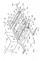
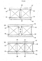
- Fig. 1 is a perspective view illustrating a part of an automated storage/retrieval system 12 employing a transferring shuttle 10 in accordance with the present invention.
- the illustrated automated storage/retrieval system 12 comprises at least one pair of left and right multi-tier racks 16L, 16R, each including a plurality of shelves 14 which are multi-tiered.
- the transferring shuttle 10 in accordance with the present invention for transferring a unit load P to and from the multi-tier racks 16L, 16R is provided at each tier or every several tiers.
- the multi-tier racks 16L, 16R accommodate unit loads P which are regularly shaped articles, such as buckets (returnable boxes made of plastics).
- Each shelf 14 in the multi-tier racks 16L, 16R has a depth (length in the left/right direction illustrated in Fig. 1 ) which is two times that of the conventional one, so that two unit loads P can be arranged in a row in the left/right lateral direction by a function of the transferring shuttle 10 in accordance with the present invention.
- a buffer station where the unit loads are transferred to and from the multi-tier racks 16L, 16R through the transferring shuttle 10 and temporarily wait or buffer when necessary, and an elevator for transferring the loads between the buffer station and the external conveyer system are provided on one end side or both end sides of the left and right multi-tier racks 16L, 16R.
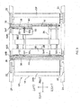
- the transferring shuttle 10 in accordance with the present invention employed in the automated storage/retrieval system 12 such as the one mentioned above is equipped with a travelling platform 18 adapted to travel horizontally between the left and right multi-tier racks 16L, 16R.
- the front and rear parts of the travelling platform 18 in its traveling direction are provided with respective chassis parts 20F, 20B which accommodate therewithin a driving motor, a power/control unit, and the like (not illustrated).
- Wheels 22 are disposed on the left and right sides of the chassis parts 20F, 20B, so as to be set on horizontally extending guide rails 24 provided with each tier of the left and right multi-tier racks 16L, 16R. Therefore, the travelling platform 18 can travel back and forth along the guide rails 24 when at least one of the wheels 22 is driven by the driving motor within the chassis part 20F or 20B.
- the front and rear chassis parts 20F, 20B of the travelling platform 18 define therebetween a unit-load carriage 26 on which the unit load P is carried. More specifically, a base frame 28 for connecting the front and rear chassis parts 20F, 20B to each other exists therebetween, while a pair of unit-load carrying plates 30 horizontally placed on the base frame 28 define the bottom face of the unit-load carriage 26. Side guides 32 are formed at respective outer edge parts (on the sides closer to the adjacent chassis parts 20F, 20B) of the unit-load carrying plates 30, while the width between the side guides 32 is made slightly greater than that of the unit load P. This allows the unit load P to move laterally leftward and rightward on the unit-load carrying plates 30 without shifting transversely or rotating.
- the unit-load carriage 26 has a length (size in the left/right lateral direction) sufficient for receiving the typical unit load P to be handled.
- the front and rear chassis parts 20F, 20B in the travelling platform 18 are provided with a pair of front and rear telescopic mechanisms 34F, 34B which hold the unit load P therebetween and take the unit load P in and out.
- the telescopic mechanisms 34F, 34B are driven in synchronization with each other, so as to be used for transferring the unit load P between the unit-load carriage 26 and the shelves 14 of the multi-tier racks 16L, 16R.
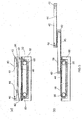
- Each of the telescopic mechanisms 34F, 34B is constituted by: a fixed rail 36 which is secured to the inward face (surface facing the unit-load carriage 26) of the chassis part 20F, 20B and extends in left and right lateral directions, i.e., horizontally lateral directions orthogonal to the traveling directions of the travelling platform 18; a first sliding rail 38 attached to the fixed rail 36 so as to be slidable in the horizontally lateral directions; and a second sliding rail 40 attached to the first sliding rail 38 so as to be slidable in the horizontally lateral directions, having the largest movable range.
- the rails 36, 38, 40 have substantially the same length, which is also substantially the same as the width of the travelling platform 18 including the wheels 22.
- the rails 36, 38, 40 attain a contracted state illustrated in Figs. 2 and 3 and Fig. 4(a) which is a schematic view and thus do not project from side faces of the travelling platform 18, thereby yielding no fear of hindering the travel.
- they can be placed in an expanded state illustrated in Fig. 4(b) when transferring the unit load P to and from the multi-tier racks 16L, 16R.
- the rails 36, 38, 40 of the telescopic mechanism 34F, 34B are dimensioned such that leading end of the second sliding rail 40 reaches a point exceeding two unit loads P aligned in the extending/retracting direction (including their required clearance therebetween) when expanded to the maximum.
- Contrivances for extending and retracting the telescopic mechanisms 34F, 34B are known ones such as those using pulleys 42 and belts (or wires) 44 illustrated in Fig. 5 , which is a principle diagram, and are configured such that, when the first sliding rail 38 is moved left or right with respect to the fixed rail 36, the second sliding rail 40 further moves in the same direction along the first sliding rail 38.
- Means for driving the first sliding rail 38 is constructed by: a rack 46 formed on a lower edge part of the first sliding rail 38 by the whole length thereof, a timing belt 48 (endless belt having inner teeth) whose outer periphery also has teeth in mesh with the rack 46, and a driving motor (not illustrated) for driving the timing belt 48.
- the timing belt 48 is mated with sprockets (see Fig. 5 ) provided at both of left and right end parts of the base frame 28, while the upper part (tight-side part) of the timing belt 48 extends over substantially the whole length between the left and right ends of the travelling platform 18.
- the rack 46 in the first sliding rail 38 is substantially wholly in mesh with the outer teeth of the timing belt 48.
- the first sliding rail 38 can be projected from the fixed rail 36 to the maximum, and the second sliding rail 40 can be moved by the same distance relative to the first sliding rail 38. This can make the moving distance of the sliding rails 38, 40 longer than that in the conventional structure using a pinion and a rack as means for driving the telescopic mechanism 34F, 34B.
- the driving motor for driving the timing belt 48 is accommodated in the chassis part 20B of the travelling platform 18.
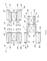
- Both ends of the second sliding rail 40 are respectively provided with outer fingers 52L, 52R for pushing and pulling the unit load P by coming into contact with its side faces.
- Each of the outer fingers 52L, 52R has one end secured to the rotary shaft of a driving motor (not illustrated) embedded in the second sliding rail 40, so as to be swingable between a position illustrated by solid lines in Fig. 2 and a position illustrated by solid lines in Fig. 3 (position illustrated by dash-double-dot lines in Fig. 2 ) when the driving motor is controlled.
- FIG. 2 is a retracted position where the outer finger 52L, 52R is sufficiently retracted from the unit-load carriage 26 and kept from interfering with the unit load P on the unit-load carriage 26 or the unit loads P on the shelves 14 of the multi-tier racks 16L, 16R.
- the position in Fig. 3 is a projected position where the outer finger 52L, 52R projects into the unit-load carriage 26 and can come into contact with an end face of the unit load P mounted on the unit-load carriage 26.
- the second sliding rail 40 is further provided with two inner fingers 54L, 54R between the left and right outer fingers 52L, 52R.
- the inner fingers 54L, 54R have the same size and shape as those of the outer fingers 52L, 52R and are attached to the second sliding rail 40 in totally the same manner as with the outer fingers 52L, 52R.
- the inner fingers 54L, 54R are arranged equidistantly from the longitudinal center point of the second sliding frame 40.
- One inner finger e.g., the left one 54L
- the outer finger the right outer finger 52R
- the moving distance of the sliding rails 38, 40 is made shorter when placing the unit load P (at the position illustrated by dash-double-dot lines in Fig. 4(b) ) on the front side of the multi-tier rack 16R (on the side closer to the transferring shuttle 10).
- the unit load P When placing the unit load P (at the position illustrated by dash-double-dot lines in Fig. 4(b) ) on the front side of the multi-tier rack 16R (on the side closer to the transferring shuttle 10), the unit load P can be moved by one stroke simply using the left outer finger without the movement of the telescopic mechanism described in the above paragraph [0031].
- Example 2 When the buffer station is on the right side of Fig. 4 while the rack storage position is on the left side, the inner finger is used for fetching the unit load. It will easily be understood that the same movement also yields the same effect when the buffer station is on the left side.
- any of the two inner fingers 54L, 54R and right outer finger 52R may be used for the unit load P on the front side when fetching the unit loads P from the right multi-tier rack 16R into the transferring shuttle 10. That is, retracting the telescopic mechanism 34F, 34B from the state illustrated in Fig. 4(b) allows the left inner finger 54L to draw the unit load P into the transferring shuttle 10.
- the right outer finger 52R may be placed at the projected position as illustrated by dash-double-dot lines in Fig. 4(b) while the inner fingers 54L, 54R are kept at the retracted positions, whereby the outer finger 52R comes into contact with the right end face of the unit load P and can draw the same into the transferring shuttle 10.
- the right outer finger 52R is used for transferring the unit load P placed in the deepest part of the multi-tier rack 16R.
- unit load P can be transferred to and from the left multi-tier rack 16L by a procedure in the reverse of that mentioned above.
- the conventional structure can move the unit load P only by the same distance as the maximum movement distance S of the sliding rail 40.
- using the inner finger 54 as in the present invention can further move the unit load P to a position exceeding the maximum movement distance of the sliding rail 40 by the distance L between the outer finger 52 and inner finger 54 as illustrated in Fig. 6(c) .
- This allows the structure of the present invention to feed the unit load P into a deeper position in the multi-tier racks 16L, 16R, so that the unit loads P can be arranged in two rows of the front and rear.
- Fig. 7(a) only one inner finger 54 may be provided as illustrated in Fig. 7(a).
- This structure can transfer two small unit loads P at the same time.
- Arranging two inner fingers 54 closer to the center as illustrated in Fig. 7(b) can handle two unit loads P at the same time as in Fig. 7(a).
- An arrangement such as the one illustrated in Fig. 7(c) can handle three unit loads P at the same time.
- three or more inner fingers may be provided when handing unit loads P having irregular forms.
- the present invention can transfer unit loads in various modes.
- three or more unit loads can be stored into the shelf sequentially from its deepest part by using the right inner finger 54R.
- two small unit loads or one small unit load and one middle unit load can be handled at the same time. That is, the right inner finger 54R and left outer finger 52L may be used such as to push respective unit loads.
- timing belt is used as the means for driving the telescopic mechanism, for example, structures using a hydraulic/pneumatic cylinder, a linear motor, and the like may also be considered.
- three-stage telescopic mechanisms are effective in that they can use the same profile as that in the conventional structure, two- and four-stage telescopic mechanisms may also be employed.
Landscapes
- Engineering & Computer Science (AREA)
- Mechanical Engineering (AREA)
- Warehouses Or Storage Devices (AREA)
Abstract
Description
- The present invention relates to an automated storage/retrieval system that includes at least one pair of multi-tier racks arranged parallel to each other and, in particular, to a transferring shuttle which is disposed between one pair of multi-tier racks and at each tier or every several tiers and horizontally travels so as to store a unit load to and retrieve a unit load from the multi-tier racks.
- For such a type of automated storage/retrieval system, a system described in, e.g. Japanese Patent Application Laid-Open No.
8-324721 - The transferring shuttle is used for storing a unit load to and retrieving a unit load from the left or right multi-tier racks. The conventional transferring shuttle comprises a travelling platform that can carry a unit load on its mid area, and a picking mechanism for taking in and out the unit load on the travelling platform in horizontally lateral directions (both left and right directions) perpendicular to the traveling directions of the platform.
- The conventional picking mechanism described in Japanese Patent Application Laid-Open No.
8-324721 - Both end parts of the second sliding rail are provided with outer fingers each of which can be moved between a position at which the outer finger projects to the unit-load carriage and a position at which the outer finger is retracted from the unit-load carriage. When these outer fingers are placed at the projected position, the fingers can press against left and right end faces of a unit load and can take in and out the unit load.
- Meanwhile, the automated storage/retrieval systems always have the need for increasing their storage capacity. For such a need, various strategies have conventionally been proposed. One of the strategies is a method that includes pushing unit loads to each shelf of the multi-tier racks as deep as possible (away from the traveling path of the transferring shuttle as farther as possible), and arranging the unit loads by, for example, two rows in the front and rear directions. For achieving this strategy, the left/right stroke of the telescopic mechanism of the transferring shuttle is required to be about two times that of the conventional one.
- However, for doubling the stroke of the telescopic mechanism by modifying a typical transferring shuttle described in Japanese Patent Application Laid-Open No.
8-324721 - It is an object of the present invention to provide a transferring shuttle which overcomes conventional problems such as those mentioned above and can store a greater number of unit loads on each shelf of multi-tier racks.
- A transferring shuttle in accordance with the present invention is used in an automated storage/retrieval system equipped with a pair of multi-tier racks arranged parallel to each other and is for transferring a unit load to and from the multi-tier racks. The transferring shuttle comprises a travelling platform, adapted to travel horizontally between the multi-tier racks, having a unit-load carriage on the center part thereof; telescopic mechanisms provided in front and rear parts of the travelling platform in its traveling direction respectively such that the unit-load carriage is between the telescopic mechanisms, each telescopic mechanism being constituted by a plurality of rails so as to be able to extend and retract in a horizontally lateral direction perpendicular to the traveling direction; and outer fingers provided at both ends of the rail having the largest movable range in the plurality of rails respectively, each finger being operable between a position at which the finger projects to the unit-load carriage and a position at which the finger is retracted from the unit-load carriage. Between the outer fingers, the rail closest to the unit-load carriage is provided with an inner finger which is operable between the projected position and the retracted position.
- In such a structure, the inner finger can push out the unit load on the unit-load carriage of the transferring shuttle. In the prior art, the outer fingers push out the unit load. On the other hand, the present invention employs a finger on the inner side to push out the unit load and minimizes the overlap between the rails, whereby the unit load can be transported to a deeper position in the multi-tier racks. This makes it possible for the multi-tier racks to accommodate a greater number of unit loads. More specifically, even in a three-stage telescopic mechanism identical to the conventional one, two unit loads can be arranged such as to align with each other in its extracting/retracting direction (two rows in the front and rear). Also, it is unnecessary to increase the number of rails constituting the telescopic mechanism, whereby there is no problem of increasing the clearance between unit loads. Since it is basically specified to add only the inner fingers, existing profiles (formed profile) can be used for the rails, whereby the manufacturing cost can be prevented from rising.
- Preferably, there are two inner fingers. When there are two inner fingers, three unit loads can be handled at the same time depending on the sizes and forms of unit loads (see Fig. 7(c)). It will also be preferred if a distance adapted to place a unit load exists between one inner finger and the outer finger farther from the one inner finger and a distance adapted to place a unit load exists between the other inner finger and the other outer finger. When the outer finger is made movable to a position exceeding a length of two unit loads aligned on the multi-tier rack adjacent to the outer finger, unit loads can be arranged in two rows in the front and rear on a shelf of the multi-tier rack.
- Each of the telescopic mechanisms may comprise a fixed rail, secured to the travelling platform, extending in a horizontally lateral direction perpendicular to the traveling direction; a first sliding rail slidably attached to the fixed rail in parallel with the horizontally lateral direction; and a second sliding rail slidably attached to the first sliding rail in parallel with the horizontally lateral direction and adapted to move in synchronization with the first sliding rail in the same direction as with the first sliding rail. In the arrangement, the second sliding rail is provided with the outer fingers and the inner finger.
- In one embodiment of the present invention, means for driving the first sliding rail preferably comprises an endless belt, arranged in the travelling platform along the fixed rail, having a tooth on an outer periphery thereof; and a rack, provided with the first sliding rail, in mesh with the tooth on the outer periphery of the belt.
- Using a belt having an outer tooth makes it possible for the first sliding rail to project more from the fixed rail. Though the amount of projection of sliding rails is severely restricted by the pinion employed in the above-mentioned conventional structure, using the belt having an outer tooth eliminates this adverse effect.
- Another embodiment of the present invention may employ one inner finger. This structure can handle two unit loads at the same time.
-
-
Fig. 1 is a partial perspective view illustrating an AS/RS employing a transferring shuttle in accordance with the present invention; -
Fig. 2 is a side view of the transferring shuttle in accordance with the present invention; -
Fig. 3 is a plan view illustrating the transferring shuttle in accordance with the present invention in a partly cutaway fashion; -
Fig. 4 is a schematic view illustrating an operation of the transferring shuttle in accordance with the present invention; -
Fig. 5 is a schematic view illustrating the principle of a telescopic mechanism in the transferring shuttle in accordance with the present invention; -
Fig. 6 is a schematic view illustrating a main part of the transferring shuttle in accordance with the present invention; and - Fig. 7 is a view illustrating some modified examples of the transferring shuttle in accordance with the present invention.
- In the following, preferred embodiments of the present invention will be explained in detail with reference to the accompanying drawings. In the drawings, the same reference characters indicated the same or equivalent portions.
-
Fig. 1 is a perspective view illustrating a part of an automated storage/retrieval system 12 employing a transferringshuttle 10 in accordance with the present invention. The illustrated automated storage/retrieval system 12 comprises at least one pair of left and rightmulti-tier racks shelves 14 which are multi-tiered. Between the multi-tier racks 16L, 16R, the transferringshuttle 10 in accordance with the present invention for transferring a unit load P to and from themulti-tier racks shelf 14 in themulti-tier racks Fig. 1 ) which is two times that of the conventional one, so that two unit loads P can be arranged in a row in the left/right lateral direction by a function of the transferringshuttle 10 in accordance with the present invention. - Though not illustrated, for transporting unit loads between the
multi-tier racks multi-tier racks shuttle 10 and temporarily wait or buffer when necessary, and an elevator for transferring the loads between the buffer station and the external conveyer system are provided on one end side or both end sides of the left and right multi-tier racks 16L, 16R. - As also illustrated in
Figs. 2 and3 , the transferringshuttle 10 in accordance with the present invention employed in the automated storage/retrieval system 12 such as the one mentioned above is equipped with atravelling platform 18 adapted to travel horizontally between the left and rightmulti-tier racks travelling platform 18 in its traveling direction are provided withrespective chassis parts Wheels 22 are disposed on the left and right sides of thechassis parts guide rails 24 provided with each tier of the left and rightmulti-tier racks platform 18 can travel back and forth along the guide rails 24 when at least one of thewheels 22 is driven by the driving motor within thechassis part - The front and
rear chassis parts platform 18 define therebetween a unit-load carriage 26 on which the unit load P is carried. More specifically, abase frame 28 for connecting the front andrear chassis parts load carrying plates 30 horizontally placed on thebase frame 28 define the bottom face of the unit-load carriage 26. Side guides 32 are formed at respective outer edge parts (on the sides closer to theadjacent chassis parts load carrying plates 30, while the width between the side guides 32 is made slightly greater than that of the unit load P. This allows the unit load P to move laterally leftward and rightward on the unit-load carrying plates 30 without shifting transversely or rotating. The unit-load carriage 26 has a length (size in the left/right lateral direction) sufficient for receiving the typical unit load P to be handled. - The front and
rear chassis parts platform 18 are provided with a pair of front and reartelescopic mechanisms telescopic mechanisms load carriage 26 and theshelves 14 of themulti-tier racks - Each of the
telescopic mechanisms rail 36 which is secured to the inward face (surface facing the unit-load carriage 26) of thechassis part platform 18; a first slidingrail 38 attached to the fixedrail 36 so as to be slidable in the horizontally lateral directions; and a second slidingrail 40 attached to the first slidingrail 38 so as to be slidable in the horizontally lateral directions, having the largest movable range. Therails platform 18 including thewheels 22. Therefore, when the travellingplatform 18 travels, therails Figs. 2 and3 andFig. 4(a) which is a schematic view and thus do not project from side faces of the travellingplatform 18, thereby yielding no fear of hindering the travel. On the other hand, they can be placed in an expanded state illustrated inFig. 4(b) when transferring the unit load P to and from themulti-tier racks rails telescopic mechanism rail 40 reaches a point exceeding two unit loads P aligned in the extending/retracting direction (including their required clearance therebetween) when expanded to the maximum. - Contrivances for extending and retracting the
telescopic mechanisms pulleys 42 and belts (or wires) 44 illustrated inFig. 5 , which is a principle diagram, and are configured such that, when the first slidingrail 38 is moved left or right with respect to the fixedrail 36, the second slidingrail 40 further moves in the same direction along the first slidingrail 38. - Means for driving the first sliding
rail 38 is constructed by: arack 46 formed on a lower edge part of the first slidingrail 38 by the whole length thereof, a timing belt 48 (endless belt having inner teeth) whose outer periphery also has teeth in mesh with therack 46, and a driving motor (not illustrated) for driving thetiming belt 48. Thetiming belt 48 is mated with sprockets (seeFig. 5 ) provided at both of left and right end parts of thebase frame 28, while the upper part (tight-side part) of thetiming belt 48 extends over substantially the whole length between the left and right ends of the travellingplatform 18. Therefore, when thetelescopic mechanism rack 46 in the first slidingrail 38 is substantially wholly in mesh with the outer teeth of thetiming belt 48. As long as the outer teeth of thetiming belt 48 and therack 46 are in mesh, the first slidingrail 38 can be projected from the fixedrail 36 to the maximum, and the second slidingrail 40 can be moved by the same distance relative to the first slidingrail 38. This can make the moving distance of the slidingrails telescopic mechanism - Though not illustrated, the driving motor for driving the
timing belt 48 is accommodated in thechassis part 20B of the travellingplatform 18. - Both ends of the second sliding
rail 40 are respectively provided withouter fingers outer fingers rail 40, so as to be swingable between a position illustrated by solid lines inFig. 2 and a position illustrated by solid lines inFig. 3 (position illustrated by dash-double-dot lines inFig. 2 ) when the driving motor is controlled. The position illustrated inFig. 2 is a retracted position where theouter finger load carriage 26 and kept from interfering with the unit load P on the unit-load carriage 26 or the unit loads P on theshelves 14 of themulti-tier racks Fig. 3 is a projected position where theouter finger load carriage 26 and can come into contact with an end face of the unit load P mounted on the unit-load carriage 26. - In this embodiment, the second sliding
rail 40 is further provided with twoinner fingers outer fingers inner fingers outer fingers rail 40 in totally the same manner as with theouter fingers inner fingers frame 40. One inner finger (e.g., the left one 54L) is paired with the outer finger (the rightouter finger 52R) farther therefrom and the distance therebetween is substantially equivalent to the length of the unit load P to be handled. - With the above-mentioned arrangement, cases where the unit load P is transferred from the transferring
shuttle 10 to themulti-tier racks - First, when putting the unit load P into the deepest part (the position farthest from the transferring shuttle 10) of the
shelf 14 in the rightmulti-tier rack 16R in the case where the unit load is mounted on the right side of the unit-load carriage 26 of the travellingplatform 18 as illustrated inFig. 4(a) , the leftinner finger 54L is pulled down to the projected position, and thetelescopic mechanism rails inner finger 54L comes into contact with the left end face of the unit load P and pushes the unit load P to move. At the point of time when the second slidingrail 40 extends to the maximum, the unit load P reaches the deepest part of theshelf 14 of themulti-tier rack 16R (Fig. 4(b) ). - It will easily be understood that the moving distance of the sliding
rails Fig. 4(b) ) on the front side of themulti-tier rack 16R (on the side closer to the transferring shuttle 10). - On the other hand, when the unit load P is placed on the left side of the unit-
load carriage 26 of the travellingplatform 18 as illustrated inFig. 4(c) , the slidingrails telescopic mechanism inner finger 54L is positioned on the left side of the left end face of the load P, and then theinner finger 54L is pulled down, whereby the unit load P can be transported to the deepest part of theshelf 14 in the rightmulti-tier rack 16R as mentioned above. - When placing the unit load P (at the position illustrated by dash-double-dot lines in
Fig. 4(b) ) on the front side of themulti-tier rack 16R (on the side closer to the transferring shuttle 10), the unit load P can be moved by one stroke simply using the left outer finger without the movement of the telescopic mechanism described in the above paragraph [0031]. - The movement described in the above paragraph [0032] becomes extra movement and thus is disadvantageous in terms of throughput. However, this movement can be avoided by contriving the movement for drawing the unit load P into the transferring
shuttle 10. New unit loads P are usually fetched from the buffer station (not illustrated) where the unit loads wait. When the buffer station is positioned on the front side (usually in the moving direction of the telescopic mechanism), both of the outer and inner fingers reach there, so that the fingers can selectively be used according to the accommodating direction of the rack at the time of fetching the unit loads. This can avoid the movement described in the above paragraph [0032].
Example 1: When the buffer station is on the right side ofFig. 4 while the rack storage position is on the right side, the outer finger is used for fetching the unit load.
Example 2: When the buffer station is on the right side ofFig. 4 while the rack storage position is on the left side, the inner finger is used for fetching the unit load.
It will easily be understood that the same movement also yields the same effect when the buffer station is on the left side. - It will also be easily understood that the movement in the above paragraph [0032] can be avoided by using any of the inner and outer fingers for fetching the unit load P when the storage position is in the front.
- Conversely, it will be understood that any of the two
inner fingers outer finger 52R may be used for the unit load P on the front side when fetching the unit loads P from the rightmulti-tier rack 16R into the transferringshuttle 10. That is, retracting thetelescopic mechanism Fig. 4(b) allows the leftinner finger 54L to draw the unit load P into the transferringshuttle 10. Alternatively, the rightouter finger 52R may be placed at the projected position as illustrated by dash-double-dot lines inFig. 4(b) while theinner fingers outer finger 52R comes into contact with the right end face of the unit load P and can draw the same into the transferringshuttle 10. - It will easily be understood that a movement similar to that mentioned above can also avoid the movement mentioned in the above paragraph [0032] at the time of dispatching to the buffer station (fetching the unit load from the rack storage position in this case).
- On the other hand, the right
outer finger 52R is used for transferring the unit load P placed in the deepest part of themulti-tier rack 16R. - One skilled in the art will easily understand that the unit load P can be transferred to and from the left
multi-tier rack 16L by a procedure in the reverse of that mentioned above. - With reference to
Fig. 6 , the structure in accordance with the present invention will now be compared with a conventional structure having onlyouter fingers 52 at both end parts of the second slidingrail 40. - When the sliding
rail 40 is moved from the state ofFig. 6(a) to the state ofFig. 6(b) , the conventional structure can move the unit load P only by the same distance as the maximum movement distance S of the slidingrail 40. By contrast, using theinner finger 54 as in the present invention can further move the unit load P to a position exceeding the maximum movement distance of the slidingrail 40 by the distance L between theouter finger 52 andinner finger 54 as illustrated inFig. 6(c) . This allows the structure of the present invention to feed the unit load P into a deeper position in themulti-tier racks - In view of this point, only one
inner finger 54 may be provided as illustrated in Fig. 7(a). This structure can transfer two small unit loads P at the same time. Arranging twoinner fingers 54 closer to the center as illustrated in Fig. 7(b) can handle two unit loads P at the same time as in Fig. 7(a). An arrangement such as the one illustrated in Fig. 7(c) can handle three unit loads P at the same time. Though not illustrated, three or more inner fingers may be provided when handing unit loads P having irregular forms. - Though a preferred embodiment of the present invention is explained in detail in the foregoing, the present invention is not limited to the above-mentioned embodiment but can be modified and altered in various ways without deviating from the spirit or scope of the present invention.
- Since the telescopic mechanism secures a large movable range, while the outer finger and inner finger can operate independently from each other, the present invention can transfer unit loads in various modes. When accommodating small unit loads in the right multi-tier rack in the structure illustrated in
Figs. 1 to 3 , for example, three or more unit loads can be stored into the shelf sequentially from its deepest part by using the rightinner finger 54R. Also, two small unit loads or one small unit load and one middle unit load can be handled at the same time. That is, the rightinner finger 54R and leftouter finger 52L may be used such as to push respective unit loads. - Though a timing belt is used as the means for driving the telescopic mechanism, for example, structures using a hydraulic/pneumatic cylinder, a linear motor, and the like may also be considered.
- Though three-stage telescopic mechanisms are effective in that they can use the same profile as that in the conventional structure, two- and four-stage telescopic mechanisms may also be employed.
Claims (7)
- A transferring shuttle (10), used in an automated storage/retrieval system (12) includes a pair of multi-tier racks (16L, 16R) arranged parallel to each other, for storing a unit load (P) to and retrieving a unit load (P) from the multi-tier racks (16L, 16R), the transferring shuttle (10) comprising:a travelling platform (18) adapted to travel horizontally between the multi-tier racks (16L, 16R), said travelling platform (18) having a unit-load carriage (26) on which the unit load (P) can be carried;respective telescopic mechanisms (34F, 34B) provided in front and rear parts of the travelling platform (18), the unit-load carriage (26) being between the telescopic mechanisms (34F, 34B), each telescopic mechanism being constituted by a plurality of rails (36, 38, 40) adapted to expand and contract in a horizontally lateral direction perpendicular to the traveling direction of the travelling platform; andrespective outer fingers (52L, 52R) provided at both ends of the rail (40) having the largest movable range in the plurality of rails (36, 38, 40), each finger being operable between a projected position where the finger projects to the unit-load carriage (26) and a retracted position where the finger is retracted from the unit-load carriage (26),the transferring shuttle (10) being characterized in that between the outer fingers (52L, 52R), the rail (40) having the largest movable range is provided with an inner finger (54) operable between the projected position and the retracted position.
- The transferring shuttle according to claim 1, characterized in that the number of the inner fingers (54L, 54R) is 2 on each side of the rail.
- The transferring shuttle according to claim 2, characterized in that a distance adapted to place a unit load (P) exists between one of the inner fingers (54L) and the outer finger (52R) farther from the one inner finger (54L), and a distance adapted to place a unit load (P) exists between the other inner finger (54R) and the other outer finger (52L).
- The transferring shuttle according to claim 3, characterized in that the outer finger (52L, 52R) is movable to a position exceeding a length of at least two unit loads P aligned on the multi-tier rack (16L, 16R) adjacent to the outer finger (52L, 52R).
- A transferring shuttle according to one of claims 1 to 4, characterized in that each of the telescopic mechanisms (34F, 34B) comprises:a fixed rail (36), secured to the travelling platform (18), extending in a horizontally lateral direction perpendicular to the traveling direction;a first sliding rail (38) slidably attached to the fixed rail (36) in parallel with the horizontally lateral direction; anda second sliding rail (40) slidably attached to the first sliding rail (38) in parallel with the horizontally lateral direction and adapted to move in synchronization with the first sliding rail (38) in the same direction as with the first sliding rail (38);wherein the second sliding rail (40) is provided with the outer fingers (52L, 52R) and the inner finger (54).
- The transferring shuttle according to claim 5, characterized in that means for driving the first sliding rail (38) comprises an endless belt (48), arranged in the travelling platform (18) along the fixed rail (36), having a tooth on an outer periphery; and a rack (46), provided with the first sliding rail (38), in mesh with the tooth on the outer periphery of the belt (48).
- A transferring shuttle according to claim 1, characterized in that the number of the inner finger (54) is 1 on each side of the rail.
Applications Claiming Priority (1)
| Application Number | Priority Date | Filing Date | Title |
|---|---|---|---|
| PCT/JP2008/069464 WO2010049987A1 (en) | 2008-10-27 | 2008-10-27 | Transfer shuttle for automated warehouse |
Publications (3)
| Publication Number | Publication Date |
|---|---|
| EP2351698A1 true EP2351698A1 (en) | 2011-08-03 |
| EP2351698A4 EP2351698A4 (en) | 2013-01-16 |
| EP2351698B1 EP2351698B1 (en) | 2014-08-20 |
Family
ID=42128366
Family Applications (1)
| Application Number | Title | Priority Date | Filing Date |
|---|---|---|---|
| EP08877699.2A Active EP2351698B1 (en) | 2008-10-27 | 2008-10-27 | Transfer shuttle for automated warehouse |
Country Status (7)
| Country | Link |
|---|---|
| US (1) | US8790061B2 (en) |
| EP (1) | EP2351698B1 (en) |
| JP (1) | JP5432917B2 (en) |
| KR (1) | KR101551997B1 (en) |
| CA (1) | CA2741840C (en) |
| ES (1) | ES2523843T3 (en) |
| WO (1) | WO2010049987A1 (en) |
Cited By (20)
| Publication number | Priority date | Publication date | Assignee | Title |
|---|---|---|---|---|
| EP2433882A1 (en) | 2010-09-22 | 2012-03-28 | TGW Mechanics GmbH | Method for storing goods and device for same |
| CN104619613A (en) * | 2012-09-06 | 2015-05-13 | 村田机械株式会社 | Transfer device |
| WO2016033628A1 (en) | 2014-09-05 | 2016-03-10 | Tgw Mechanics Gmbh | Automated rack storage system and method for safely operating it |
| CN104619613B (en) * | 2012-09-06 | 2016-11-30 | 村田机械株式会社 | Transfer device |
| CN107428463A (en) * | 2014-12-10 | 2017-12-01 | 瑞仕格赢麦迪科有限公司 | Load storage device |
| CN107667061A (en) * | 2015-04-22 | 2018-02-06 | Tgw机械有限公司 | Method and warehouse system for storing items in racks |
| WO2018185231A1 (en) | 2017-04-07 | 2018-10-11 | Dematic Gmbh | Method and system for transporting units within a storage facility |
| EP3431417A1 (en) | 2015-05-29 | 2019-01-23 | TGW Mechanics GmbH | Storage system |
| RU2696635C2 (en) * | 2013-10-15 | 2019-08-05 | ФАРМАТЕК С.р.л. | Unit and procedure for automated transfer of box elements |
| EP3712815A4 (en) * | 2017-11-14 | 2021-01-13 | Hai Robotics Co., Ltd. | TRANSPORT ROBOT AND PICKUP PROCESS BASED ON A TRANSPORT ROBOT |
| US11396424B2 (en) | 2017-11-14 | 2022-07-26 | Hai Robotics Co., Ltd. | Handling robot |
| WO2022178567A1 (en) | 2021-02-26 | 2022-09-01 | Tgw Mechanics Gmbh | Method and shelf storage system with increased safety when stopping a storage and retrieval machine |
| US11465840B2 (en) | 2017-11-14 | 2022-10-11 | Hai Robotics Co., Ltd. | Handling robot |
| US11542135B2 (en) | 2019-02-01 | 2023-01-03 | Hai Robotics Co., Ltd. | Handling robot |
| US11597598B2 (en) | 2019-02-01 | 2023-03-07 | Hai Robotics Co., Ltd. | Handling robot |
| US11655099B2 (en) | 2017-11-14 | 2023-05-23 | Hai Robotics Co., Ltd. | Handling robot |
| WO2024192454A1 (en) | 2023-03-21 | 2024-09-26 | Tgw Mechanics Gmbh | Transport vehicle for transporting piece goods, and method for manufacturing a cover element therefor |
| US12103771B2 (en) | 2017-11-14 | 2024-10-01 | Hai Robotics Co., Ltd. | Handling robot |
| WO2024216322A2 (en) | 2023-04-21 | 2024-10-24 | Tgw Mechanics Gmbh | Transport vehicle for transport, and method for handling piece goods in a storage system |
| US12330870B2 (en) | 2017-11-14 | 2025-06-17 | Hai Robotics Co., Ltd. | Handling robot |
Families Citing this family (158)
| Publication number | Priority date | Publication date | Assignee | Title |
|---|---|---|---|---|
| KR20110049894A (en) | 2008-09-03 | 2011-05-12 | 디마틱 어카운팅 서비시즈 게엠베하 | Automated Goods Receipt / Receipt System |
| US9321591B2 (en) | 2009-04-10 | 2016-04-26 | Symbotic, LLC | Autonomous transports for storage and retrieval systems |
| US8594835B2 (en) | 2009-04-10 | 2013-11-26 | Symbotic, LLC | Control system for storage and retrieval systems |
| AT508361B1 (en) * | 2009-08-17 | 2011-01-15 | Knapp Ag | STORAGE SYSTEM |
| EP2536649B1 (en) | 2010-02-19 | 2016-05-25 | Dematic Corp. | Goods-to-person picking station and picking method |
| US9522781B2 (en) | 2010-09-30 | 2016-12-20 | Dematic Systems Gmbh | Shuttle for automated warehouse |
| US9561905B2 (en) | 2010-12-15 | 2017-02-07 | Symbotic, LLC | Autonomous transport vehicle |
| US9187244B2 (en) | 2010-12-15 | 2015-11-17 | Symbotic, LLC | BOT payload alignment and sensing |
| US9499338B2 (en) | 2010-12-15 | 2016-11-22 | Symbotic, LLC | Automated bot transfer arm drive system |
| US8696010B2 (en) | 2010-12-15 | 2014-04-15 | Symbotic, LLC | Suspension system for autonomous transports |
| US11078017B2 (en) | 2010-12-15 | 2021-08-03 | Symbotic Llc | Automated bot with transfer arm |
| US8965619B2 (en) | 2010-12-15 | 2015-02-24 | Symbotic, LLC | Bot having high speed stability |
| DE102011010544A1 (en) * | 2011-02-07 | 2012-08-09 | Eisenmann Ag | Tragbahnförderer and conveyor system with such |
| AT511162A1 (en) | 2011-02-08 | 2012-09-15 | Tgw Mechanics Gmbh | BAY WAREHOUSE SYSTEM |
| AT511140B1 (en) | 2011-02-08 | 2014-06-15 | Tgw Mechanics Gmbh | REGULAR STORAGE SYSTEM AND METHOD FOR OPERATING THE SAME |
| AT511138B1 (en) | 2011-02-08 | 2015-01-15 | Tgw Mechanics Gmbh | A SINGLE SHIELDING DEVICE FOR INCL. DISTRIBUTION OF CHARGES IN A BZW. FROM A REGULAR STORAGE |
| AT511137B1 (en) | 2011-02-08 | 2020-10-15 | Tgw Mechanics Gmbh | SHELF STORAGE SYSTEM AND METHOD OF OPERATING THE SAME |
| EP2683635A2 (en) * | 2011-03-11 | 2014-01-15 | Subramanian Venkatraman | Multi level automated storage and handling system for containers and bulky objects |
| FI123784B (en) * | 2011-03-25 | 2013-10-31 | Konecranes Oyj | Arrangement to dampen the swinging of the loading member in the crane |
| US9056719B2 (en) * | 2011-03-29 | 2015-06-16 | Murata Machinery, Ltd. | Automatic storage system |
| CN103459273B (en) | 2011-04-04 | 2015-06-03 | 德马泰克财务服务有限公司 | Access emergency brakes for track-guided vehicles |
| AT511623B1 (en) | 2011-07-08 | 2016-01-15 | Tgw Mechanics Gmbh | BAY WAREHOUSE SYSTEM |
| AT511641A3 (en) | 2011-07-08 | 2013-07-15 | Tgw Mechanics Gmbh | LOAD TAKE-UP MEANS FOR LOADING AND REMOVING LOADED MATERIALS |
| AT14347U1 (en) * | 2011-07-22 | 2015-09-15 | Tgw Mechanics Gmbh | Conveying vehicle, in particular self-propelled shuttle, for a shelf warehouse |
| AT511759A3 (en) | 2011-07-22 | 2013-07-15 | Tgw Mechanics Gmbh | CONVEYOR VEHICLE, IN PARTICULAR SELF-EXECUTIVE SHUTTLE, FOR A SHELTER |
| DE102011084551A1 (en) * | 2011-10-14 | 2013-04-18 | Krones Aktiengesellschaft | Storage and retrieval unit and picking warehouse |
| BE1020361A3 (en) * | 2011-12-23 | 2013-08-06 | Alvey Nv | PICK-AND-PLACE DEVICE. |
| ES2492530T3 (en) * | 2012-01-30 | 2014-09-09 | Carefusion Germany 326 Gmbh | Procedure to recover medication containers |
| CN102616518B (en) * | 2012-03-29 | 2013-12-11 | 缪慰时 | Remote control shuttle vehicle for high-density automatic warehouse |
| JP6271509B2 (en) * | 2012-04-09 | 2018-01-31 | オペックス コーポレーション | Method and apparatus for sorting or obtaining items |
| DE102012107176A1 (en) | 2012-08-06 | 2014-02-06 | Dematic Accounting Services Gmbh | Method for providing transport units from a warehouse |
| DE102012107438A1 (en) | 2012-08-14 | 2014-03-27 | Dematic Accounting Services Gmbh | Method for manufacturing rack gear used in telescopic arm of shuttle for e.g. inserting containers into storage compartment in high rack warehouse, involves shaping tooth blanks into teeth by action in direction perpendicular to sheet plane |
| US9701471B2 (en) * | 2012-08-31 | 2017-07-11 | Murata Machinery, Ltd. | Transfer device |
| CN104428219B (en) * | 2012-09-05 | 2016-04-27 | 村田机械株式会社 | Transfer device |
| CN104428218B (en) * | 2012-09-05 | 2015-11-25 | 村田机械株式会社 | Transfer device |
| DE102012017985A1 (en) * | 2012-09-12 | 2014-04-03 | Servus Intralogistics Gmbh | Transportation robot i.e. rail-bound transportation robot, has longitudinal conveyer designed as single-acting pick arm for handling of containers on storage bin and arranged on pivotable pawls for positive gripping of containers |
| DE102012220193A1 (en) * | 2012-11-06 | 2014-05-08 | Kardex Produktion Deutschland Gmbh | Storage goods extractor for an automatic storage system |
| KR101422685B1 (en) * | 2012-12-28 | 2014-07-23 | 주식회사 유일에프에이 | Rail-moving cart assembly for rack |
| US9122566B2 (en) | 2013-03-08 | 2015-09-01 | Bastian Solutions, Llc | Robotic material handling system |
| US20140271069A1 (en) * | 2013-03-14 | 2014-09-18 | Illinois Tool Works Inc. | Storage Carts |
| US9067740B2 (en) * | 2013-03-15 | 2015-06-30 | Intelligrated Headquarters, Llc | Remotely driven shuttle car |
| US9139363B2 (en) | 2013-03-15 | 2015-09-22 | John Lert | Automated system for transporting payloads |
| EP2815976A1 (en) * | 2013-06-17 | 2014-12-24 | Airbus Operations GmbH | Vehicle comprising a transport arrangement |
| DE102013011860A1 (en) | 2013-07-16 | 2015-01-22 | Servus Intralogistics Gmbh | Transport robot with collection device for transport goods |
| DE102013107873A1 (en) * | 2013-07-23 | 2015-01-29 | SSI Schäfer PEEM GmbH | Transport vehicle as well as base frame and modular system for transport vehicle |
| JP5884787B2 (en) * | 2013-08-05 | 2016-03-15 | トヨタ自動車株式会社 | Transfer device and transfer method |
| DE102013013274A1 (en) * | 2013-08-09 | 2015-02-12 | Servus Intralogistics Gmbh | Transport robot with lifting unit for transport goods |
| JP6523296B2 (en) | 2013-09-13 | 2019-05-29 | シムボティック エルエルシー | Automatic storage and retrieval system |
| SE538974C2 (en) * | 2013-12-03 | 2017-03-07 | Texo Application Ab | Emergency stop device for shuttles, and storage system with rails and shuttles |
| EP2952454A1 (en) * | 2014-06-02 | 2015-12-09 | Dematic Systems GmbH | Method of extending the load handling range of an automated storage/retrieval system |
| WO2016007330A1 (en) | 2014-07-08 | 2016-01-14 | Dematic Corp. | Lift configuration for carriage-based warehouse |
| NL2013200B1 (en) * | 2014-07-16 | 2016-07-14 | Vanderlande Ind Bv | System for storing product holders. |
| AT14533U1 (en) * | 2014-08-05 | 2016-01-15 | Stickler Immobilien Gmbh | Shuttle for a warehouse |
| MX2017002158A (en) | 2014-08-20 | 2017-08-10 | Dematic Corp | Dynamic rate matching for material handling. |
| DK3193807T3 (en) * | 2014-09-18 | 2021-10-18 | Ideassociates Iom Ltd | A wheeled transportation device |
| JP6350166B2 (en) * | 2014-09-19 | 2018-07-04 | 株式会社ダイフク | Goods transport cart |
| US9409728B2 (en) | 2014-11-03 | 2016-08-09 | Bastian Solutions, Llc | Automated case flow buffer |
| US9884719B2 (en) | 2014-12-12 | 2018-02-06 | Symbotic, LLC | Storage and retrieval system |
| JP6398680B2 (en) * | 2014-12-12 | 2018-10-03 | 村田機械株式会社 | Side arm transfer equipment |
| AT516633A1 (en) | 2014-12-18 | 2016-07-15 | Tgw Logistics Group Gmbh | Bearing arrangement with improved energy balance between storage and retrieval units |
| US10294027B2 (en) * | 2015-01-09 | 2019-05-21 | Carefusion Germany 326 Gmbh | Operating device for an order-picking apparatus |
| US11893533B2 (en) | 2015-01-16 | 2024-02-06 | Symbotic Llc | Storage and retrieval system |
| US12280953B2 (en) | 2015-01-16 | 2025-04-22 | Symbotic Llc | Storage and retrieval system |
| US10974897B2 (en) | 2015-01-16 | 2021-04-13 | Symbotic Llc | Storage and retrieval system |
| US10214355B2 (en) | 2015-01-16 | 2019-02-26 | Symbotic, LLC | Storage and retrieval system |
| US10521767B2 (en) | 2015-01-16 | 2019-12-31 | Symbotic, LLC | Storage and retrieval system |
| US10102496B2 (en) | 2015-01-16 | 2018-10-16 | Symbotic, LLC | Storage and retrieval system |
| US9856083B2 (en) | 2015-01-16 | 2018-01-02 | Symbotic, LLC | Storage and retrieval system |
| US11254502B2 (en) | 2015-01-16 | 2022-02-22 | Symbotic Llc | Storage and retrieval system |
| US9850079B2 (en) | 2015-01-23 | 2017-12-26 | Symbotic, LLC | Storage and retrieval system transport vehicle |
| KR101717447B1 (en) * | 2015-05-21 | 2017-03-20 | 주식회사 에스에프에이 | Transfer shuttle and automated warehouse system using the same |
| US11142398B2 (en) | 2015-06-02 | 2021-10-12 | Alert Innovation Inc. | Order fulfillment system |
| EP3650375A1 (en) | 2015-06-02 | 2020-05-13 | Alert Innovation Inc. | Storage and retrieval system |
| US11203486B2 (en) | 2015-06-02 | 2021-12-21 | Alert Innovation Inc. | Order fulfillment system |
| KR101725644B1 (en) | 2015-07-28 | 2017-04-11 | 한국항공대학교산학협력단 | Moving shuttle for goods destination system |
| KR101662955B1 (en) | 2015-07-28 | 2016-10-05 | 한국항공대학교산학협력단 | Moving shuttle for goods destination system |
| CA2938850C (en) | 2015-08-12 | 2022-02-22 | Axium Robotic and Automation ULC | System and method for palletizing |
| JP7004424B2 (en) * | 2015-10-30 | 2022-01-21 | トーヨーカネツ株式会社 | Three-dimensional automated warehouse |
| EP3166058A1 (en) | 2015-11-09 | 2017-05-10 | Dematic Systems GmbH | Method of fulfilling orders in a warehouse with an order fulfillment area |
| CN105416945B (en) * | 2015-12-02 | 2017-09-08 | 国网浙江省电力公司湖州供电公司 | Goods fetching device and the cargo handling equipment using the device |
| EP3182348A1 (en) | 2015-12-17 | 2017-06-21 | Dematic Systems GmbH | Method of order fulfilling by making storage units available from a storage facility in a desired sequence at a picking station |
| JP7206454B2 (en) * | 2016-01-08 | 2023-01-18 | トーヨーカネツ株式会社 | Three-dimensional automated warehouse |
| USD857072S1 (en) | 2016-01-22 | 2019-08-20 | Symbotic, LLC | Automated guided vehicle |
| JP6673031B2 (en) * | 2016-06-03 | 2020-03-25 | 村田機械株式会社 | Carrier |
| EP3272679B1 (en) | 2016-07-19 | 2020-10-21 | Dematic GmbH | Automatically centring load support for shuttle vehicles having a variable receiving width |
| DE112017004045T5 (en) * | 2016-09-26 | 2019-05-23 | Intelligrated Headquarters, Llc | FULLY VALIDATED MATERIAL TRANSPORTATION WITH PENDULUM CONTAINER SYSTEM |
| WO2018094286A1 (en) | 2016-11-17 | 2018-05-24 | Alert Innovation Inc. | Automated-service retail system and method |
| CA3302758A1 (en) | 2016-11-29 | 2026-03-31 | Symbotic Llc | Automated retail supply chain and inventory management system |
| JP2020504066A (en) | 2017-01-10 | 2020-02-06 | アラート イノヴェイション インコーポレイテッド | Automatic store with exchangeable automatic mobile robot |
| JP7478320B2 (en) | 2017-02-24 | 2024-05-07 | ウォルマート アポロ リミテッド ライアビリティ カンパニー | Inventory control system and method |
| CN110636981B (en) | 2017-03-08 | 2021-10-26 | 雷勃美国公司 | Package sorting and conveying module and system and method thereof |
| US10532894B2 (en) | 2017-03-10 | 2020-01-14 | Regal Beloit America, Inc. | Modular transfer units, systems, and methods |
| CN106882529A (en) * | 2017-04-14 | 2017-06-23 | 杭州南江机器人股份有限公司 | A kind of AGV docking mechanisms and AGV |
| US10744894B2 (en) | 2017-05-08 | 2020-08-18 | Bastian Solutions, Llc | Charging system for an autonomous mobile unit |
| US10322505B2 (en) * | 2017-07-20 | 2019-06-18 | Becton Dickinson Rowa Germany Gmbh | Controller for a commissioning device |
| US11117743B2 (en) | 2017-09-28 | 2021-09-14 | Symbotic Llc | Storage and retrieval system |
| FR3072371A1 (en) * | 2017-10-12 | 2019-04-19 | Exotec Solutions | SYSTEM FOR STORING AND TRANSPORTING OBJECTS STORED IN WAREHOUSE STORAGE |
| EP3704037A4 (en) * | 2017-11-03 | 2020-12-09 | Labrador Systems, Inc. | AUTONOMOUS HOME ROBOT SYSTEMS FOR FINDING AND TRANSPORTING ITEMS |
| WO2019104095A2 (en) | 2017-11-22 | 2019-05-31 | Regal Beloit America, Inc. | Modular sortation units, systems, and methods |
| US10864641B2 (en) | 2017-12-01 | 2020-12-15 | Bastian Solutions, Llc | End effector |
| KR101917978B1 (en) | 2018-02-27 | 2018-11-12 | 이기현 | Tray shuttle |
| JP2019147669A (en) * | 2018-02-28 | 2019-09-05 | 村田機械株式会社 | Side arm type transfer device |
| US11390504B2 (en) | 2018-03-20 | 2022-07-19 | Bastian Solutions, Llc | Lift mechanism for robotic shuttle system |
| CA3117483A1 (en) | 2018-03-20 | 2019-09-26 | Bastian Solutions, Llc | Robotic shuttle system |
| KR102466772B1 (en) * | 2018-05-02 | 2022-11-14 | 주식회사 엘지화학 | Conveyor belt |
| NO344750B1 (en) * | 2018-06-12 | 2020-04-06 | Autostore Tech As | Unloading arrangement and unloading station, as well as method of unloading an item from a storage container |
| US10435252B1 (en) | 2018-10-08 | 2019-10-08 | Becton Dickinson Rowa Germany Gmbh | Operating device for placing or retrieving bottle-like piece goods |
| KR102078227B1 (en) * | 2018-11-26 | 2020-02-19 | (주)랩투마켓 | the module type shuttle structure with replaceable cargo box |
| KR102147394B1 (en) * | 2018-11-26 | 2020-08-24 | (주)랩투마켓 | the improved shuttle structure with length adjustable arm |
| KR102142194B1 (en) * | 2018-11-26 | 2020-08-06 | (주)일양엔지니어링 | Shuttle transfering goods |
| KR102078228B1 (en) * | 2018-11-26 | 2020-02-19 | (주)랩투마켓 | the module type shuttle structure with lifting cargo box |
| ES2956870T3 (en) | 2018-11-28 | 2023-12-29 | Autostore Tech As | Storage container for automated storage and retrieval system |
| JP7063295B2 (en) * | 2019-03-22 | 2022-05-09 | 株式会社ダイフク | Goods carrier |
| DE102019204762B4 (en) * | 2019-04-03 | 2024-11-07 | Audi Ag | load handling device for an automated warehouse |
| CN110027832A (en) * | 2019-05-16 | 2019-07-19 | 山东大学 | A kind of shelf goods cage transfer shuttle and its application |
| USD898092S1 (en) * | 2019-06-03 | 2020-10-06 | Storage Management Sysem (Pty) Ltd. | Bogie for a warehousing shuttle |
| KR102247616B1 (en) * | 2019-06-10 | 2021-05-04 | (주)엑시스 소프트웨어 엔지니어링 | Loader |
| KR102247613B1 (en) * | 2019-06-10 | 2021-05-04 | (주)엑시스 소프트웨어 엔지니어링 | Loader |
| DE102019209097A1 (en) * | 2019-06-24 | 2020-12-24 | Gebhardt Fördertechnik GmbH | Device and method for transporting cargo in a storage and removal system |
| CN111776559B (en) * | 2019-09-09 | 2021-10-15 | 北京京东乾石科技有限公司 | warehouse shuttle |
| CN211056639U (en) * | 2019-09-17 | 2020-07-21 | 深圳市海柔创新科技有限公司 | Fork and handling robot |
| US11807451B2 (en) | 2019-09-17 | 2023-11-07 | Hai Robotics Co., Ltd. | Fork and carrying robot |
| KR102336620B1 (en) | 2019-09-23 | 2021-12-09 | 주식회사 티에스피지 | Telescopic fork Device for moving cart |
| JP7429289B2 (en) * | 2019-10-23 | 2024-02-07 | シャンハイ クイックトロン インテリジェント テクノロジー カンパニー リミテッド | Expanding/contracting device and transfer robot |
| US11407587B1 (en) * | 2019-11-04 | 2022-08-09 | Amazon Technologies, Inc. | Automated container retrieval and delivery systems |
| CN113401548B (en) | 2020-03-16 | 2023-07-11 | 因特利格雷特总部有限责任公司 | Automatic shuttle system for multi-depth storage rack |
| IT202000005632A1 (en) * | 2020-03-17 | 2021-09-17 | Automha S P A | Device for picking up and / or depositing items for automatic warehouses. |
| WO2021220686A1 (en) * | 2020-04-30 | 2021-11-04 | 村田機械株式会社 | Traveling platform, and automatic storehouse |
| DE102020111980A1 (en) * | 2020-05-04 | 2021-11-04 | Rocket Solution Gmbh | Shuttle and shelving system |
| US12172837B2 (en) | 2020-05-27 | 2024-12-24 | Dematic Corp. | Robotic automated storage and retrieval system and method of storing articles |
| USD1018617S1 (en) * | 2020-08-13 | 2024-03-19 | Opex Corporation | Automated storage and retrieval vehicle |
| EP3960656A1 (en) | 2020-08-24 | 2022-03-02 | Dematic GmbH | System for storage of goods carriers |
| DE102020213046A1 (en) | 2020-10-15 | 2022-04-21 | Gebhardt Fördertechnik GmbH | Storage and withdrawal system as well as a storage rack |
| US11912511B2 (en) * | 2020-12-09 | 2024-02-27 | Becton Dickinson Rowa Germany Gmbh | Gripper and transport system for a picking device |
| USD982047S1 (en) * | 2020-12-21 | 2023-03-28 | Beijing Jingdong Qianshi Technology Co., Ltd. | Logistics robot |
| CN113233064A (en) * | 2021-01-27 | 2021-08-10 | 威海天润智能科技有限公司 | Stack vertical bin |
| EP4341175A1 (en) * | 2021-05-17 | 2024-03-27 | Ocado Innovation Limited | Mechanical handling apparatus |
| KR102339212B1 (en) * | 2021-05-20 | 2021-12-14 | 주식회사 에이피씨소프트 | transfer robot for automatic warehouse |
| TWI837875B (en) * | 2021-10-12 | 2024-04-01 | 美商靈巧公司 | Robotic stack pusher system, method for loading a payload to a robot workspace or otherwise to a robotic stack mover system, and computer program product embodied in a non-transitory computer readable medium |
| USD1104856S1 (en) * | 2021-10-20 | 2025-12-09 | Intelligrated Headquarters, Llc | Shuttle car |
| JP7501496B2 (en) * | 2021-11-09 | 2024-06-18 | 株式会社ダイフク | Transfer Equipment |
| JP7515790B2 (en) * | 2022-01-21 | 2024-07-16 | 村田機械株式会社 | Automatic warehouse |
| CN114476468A (en) * | 2022-02-28 | 2022-05-13 | 北京京东乾石科技有限公司 | Shuttle and shuttle access system |
| CN114803242B (en) * | 2022-04-01 | 2024-01-16 | 萨驰智能装备股份有限公司 | Material conveying system and control method |
| CZ2022164A3 (en) * | 2022-04-21 | 2023-11-01 | RUR Robotics s.r.o. | Storage system, trolley for storage system and rack structure |
| CN114916694B (en) * | 2022-04-29 | 2023-05-26 | 成都琅思智能设备有限公司 | Automatic batch transportation and airing system for tobacco leaves and airing and frame-unloading method |
| JP2023167984A (en) * | 2022-05-13 | 2023-11-24 | 村田機械株式会社 | Automatic warehouse |
| EP4310026A1 (en) * | 2022-07-22 | 2024-01-24 | Goya Systec S.R.L. | Transport vehicle for automated storage |
| JP2024030797A (en) * | 2022-08-25 | 2024-03-07 | 株式会社椿本チエイン | Transfer system |
| TWM636964U (en) * | 2022-10-05 | 2023-01-21 | 張榮傑 | Automatic warehousing trolley conveying device |
| USD1101012S1 (en) | 2023-02-21 | 2025-11-04 | Intelligrated Headquarters, Llc | Shuttle car |
| JPWO2024190084A1 (en) * | 2023-03-10 | 2024-09-19 | ||
| US12528648B1 (en) * | 2023-03-13 | 2026-01-20 | Amazon Technologies, Inc. | Systems and methods for payload shuttles for efficiently loading and unloading containers |
| KR20240157142A (en) * | 2023-04-24 | 2024-11-01 | 엘지전자 주식회사 | Robot System |
| GB202310834D0 (en) * | 2023-07-14 | 2023-08-30 | Richmond Design And Marketing Ltd | Apparatus, systems, and vehicles for airside container loading and unloading |
| USD1080131S1 (en) * | 2024-03-06 | 2025-06-17 | Mecalux, S.A. | Shuttle lift system |
| JP2026052244A (en) * | 2024-09-11 | 2026-03-24 | 株式会社ダイフク | Transfer equipment |
| CN119706162B (en) * | 2025-02-26 | 2025-08-01 | 山东深蓝机器股份有限公司 | Logistics shuttle |
Citations (2)
| Publication number | Priority date | Publication date | Assignee | Title |
|---|---|---|---|---|
| EP0733563A1 (en) | 1995-03-22 | 1996-09-25 | Toyokanetsu Kabushiki Kaisha | Merchandise handling equipment and merchandise storage equipment |
| US20030185656A1 (en) | 2002-03-29 | 2003-10-02 | Rudolf Hansl | Support frame for a telescopic arm of a load-handling system and a method of manipulating storage units |
Family Cites Families (25)
| Publication number | Priority date | Publication date | Assignee | Title |
|---|---|---|---|---|
| JPS5332586B2 (en) * | 1973-01-19 | 1978-09-08 | ||
| FI76039C (en) * | 1986-09-10 | 1988-09-09 | Seppo Kalervo Suominen | FOERFARANDE OCH TRANSPORTVAGN FOER HINDRANDE AV KUMULERING AV FEL VID KOLLIPARKERING I LAGER AV SEKVENSTYP. |
| JPS63165205A (en) | 1986-12-25 | 1988-07-08 | Itoki Kosakusho Co Ltd | Automatic custody searching device |
| JPH08175620A (en) | 1994-12-27 | 1996-07-09 | Itoki Crebio Corp | Convey in/out mechanism for automatic storage retrieving device |
| JP3335786B2 (en) | 1994-12-27 | 2002-10-21 | 株式会社イトーキクレビオ | Loading / unloading mechanism in automatic storage and retrieval device |
| JP3358920B2 (en) | 1995-05-31 | 2002-12-24 | 株式会社イトーキクレビオ | Moving trolley in automated warehouse |
| JP3369392B2 (en) | 1996-03-08 | 2003-01-20 | 株式会社ダイフク | Article storage facility |
| US5839873A (en) * | 1996-03-28 | 1998-11-24 | Hk Systems, Inc. | Storage and retrieval machine with pre-tensioned shuttle guides |
| US6619902B1 (en) * | 1997-02-11 | 2003-09-16 | Stein & Associates, P.C. | Automated storage and retrieval system and indexing/insertion extraction mechanism therefor |
| JPH10297712A (en) | 1997-04-25 | 1998-11-10 | Murata Mach Ltd | Article storage device |
| IT1294287B1 (en) * | 1997-07-30 | 1999-03-24 | Fata Automation | CELL WAREHOUSE WITH HYDROPNEUMATIC HANDLING TRANSPORT WAGONS |
| JP3887904B2 (en) * | 1997-09-10 | 2007-02-28 | 株式会社豊田自動織機 | Control device for transfer device for stacker crane |
| JP3603992B2 (en) * | 1999-01-19 | 2004-12-22 | 株式会社ダイフク | Article transfer device and article storage facility |
| JP2003048604A (en) | 2001-08-01 | 2003-02-21 | Nippon Yusoki Co Ltd | Automated warehouse system |
| WO2003019425A1 (en) | 2001-08-23 | 2003-03-06 | Tgw Transportgeräte Gmbh & Co.Kg | Interim storage system for identified goods and method for transferring ordered goods |
| JP3910129B2 (en) | 2002-09-30 | 2007-04-25 | 株式会社イトーキ | Automatic warehouse |
| DE202004004620U1 (en) * | 2003-03-28 | 2004-08-12 | TGW-Transportgeräte-Ges.m.b.H. & Co. KG | Automated warehousing system has articles stored in vertically stacked compartments accessed by handling system |
| AT500228B1 (en) * | 2003-05-20 | 2007-07-15 | Tgw Transportgeraete Gmbh | TELESKOPSCHUBARM, ESPECIALLY FOR A LASTEUFNAHMEVORRICHTUNG |
| US7735631B2 (en) * | 2003-09-03 | 2010-06-15 | Siemens Aktiengesellschaft | Mail processing system and method of delivering articles to delivery locations therein |
| JP2006096522A (en) | 2004-09-29 | 2006-04-13 | Daido Steel Co Ltd | Three-dimensional warehouse |
| DE102005009695A1 (en) * | 2005-02-28 | 2006-08-31 | Keuro Besitz Gmbh & Co Edv-Dienstleistungs Kg | Shelf storage and method for relocating stored goods in a shelf warehouse |
| EP1772400A1 (en) * | 2005-10-06 | 2007-04-11 | Stöcklin Logistik AG | Load carrying device having telescopic booms and adjustable pushers |
| US7686560B2 (en) * | 2005-12-08 | 2010-03-30 | Conestoga Cold Storage | Rack, conveyor and shuttle automated pick system |
| JP4415397B2 (en) | 2007-09-03 | 2010-02-17 | 村田機械株式会社 | Stacker crane |
| KR20110049894A (en) | 2008-09-03 | 2011-05-12 | 디마틱 어카운팅 서비시즈 게엠베하 | Automated Goods Receipt / Receipt System |
-
2008
- 2008-10-27 JP JP2010535531A patent/JP5432917B2/en active Active
- 2008-10-27 CA CA2741840A patent/CA2741840C/en active Active
- 2008-10-27 EP EP08877699.2A patent/EP2351698B1/en active Active
- 2008-10-27 ES ES08877699.2T patent/ES2523843T3/en active Active
- 2008-10-27 KR KR1020117010686A patent/KR101551997B1/en active Active
- 2008-10-27 WO PCT/JP2008/069464 patent/WO2010049987A1/en not_active Ceased
- 2008-10-27 US US12/446,534 patent/US8790061B2/en active Active
Patent Citations (2)
| Publication number | Priority date | Publication date | Assignee | Title |
|---|---|---|---|---|
| EP0733563A1 (en) | 1995-03-22 | 1996-09-25 | Toyokanetsu Kabushiki Kaisha | Merchandise handling equipment and merchandise storage equipment |
| US20030185656A1 (en) | 2002-03-29 | 2003-10-02 | Rudolf Hansl | Support frame for a telescopic arm of a load-handling system and a method of manipulating storage units |
Cited By (38)
| Publication number | Priority date | Publication date | Assignee | Title |
|---|---|---|---|---|
| EP2433882A1 (en) | 2010-09-22 | 2012-03-28 | TGW Mechanics GmbH | Method for storing goods and device for same |
| CN104619613A (en) * | 2012-09-06 | 2015-05-13 | 村田机械株式会社 | Transfer device |
| CN104619613B (en) * | 2012-09-06 | 2016-11-30 | 村田机械株式会社 | Transfer device |
| RU2696635C2 (en) * | 2013-10-15 | 2019-08-05 | ФАРМАТЕК С.р.л. | Unit and procedure for automated transfer of box elements |
| WO2016033628A1 (en) | 2014-09-05 | 2016-03-10 | Tgw Mechanics Gmbh | Automated rack storage system and method for safely operating it |
| EP3505466A1 (en) | 2014-09-05 | 2019-07-03 | TGW Mechanics GmbH | Automated shelf storage system and method for reliably operating the same |
| CN107428463A (en) * | 2014-12-10 | 2017-12-01 | 瑞仕格赢麦迪科有限公司 | Load storage device |
| CN107667061B (en) * | 2015-04-22 | 2020-07-24 | Tgw机械有限公司 | Method and warehouse system for storing pieces in racks |
| CN107667061A (en) * | 2015-04-22 | 2018-02-06 | Tgw机械有限公司 | Method and warehouse system for storing items in racks |
| DE202016009161U1 (en) | 2015-04-22 | 2023-03-28 | Tgw Mechanics Gmbh | storage system |
| EP3286111B1 (en) | 2015-04-22 | 2018-11-07 | TGW Mechanics GmbH | Method for transferring part-load consignments to a storage rack for storage, and storage system |
| DE202016009160U1 (en) | 2015-04-22 | 2023-03-28 | Tgw Mechanics Gmbh | storage system |
| EP3431417A1 (en) | 2015-05-29 | 2019-01-23 | TGW Mechanics GmbH | Storage system |
| US10399773B2 (en) | 2015-05-29 | 2019-09-03 | Tgw Mechanics Gmbh | Transport vehicle and method for storing or removing piece goods, and storage system |
| EP3444205A1 (en) | 2015-05-29 | 2019-02-20 | TGW Mechanics GmbH | Method for storing different piece goods in a storage rack |
| WO2018185231A1 (en) | 2017-04-07 | 2018-10-11 | Dematic Gmbh | Method and system for transporting units within a storage facility |
| US11142400B2 (en) | 2017-04-07 | 2021-10-12 | Dematic Gmbh | Method and system for transporting units within a storage facility |
| US11794995B2 (en) | 2017-11-14 | 2023-10-24 | Hai Robotics Co., Ltd. | Handling robot |
| US12103771B2 (en) | 2017-11-14 | 2024-10-01 | Hai Robotics Co., Ltd. | Handling robot |
| US11465840B2 (en) | 2017-11-14 | 2022-10-11 | Hai Robotics Co., Ltd. | Handling robot |
| US12330870B2 (en) | 2017-11-14 | 2025-06-17 | Hai Robotics Co., Ltd. | Handling robot |
| US12291396B2 (en) | 2017-11-14 | 2025-05-06 | Hai Robotics Co., Ltd. | Method for controlling warehouse robot to store and fetch inventory materials |
| US11396424B2 (en) | 2017-11-14 | 2022-07-26 | Hai Robotics Co., Ltd. | Handling robot |
| US11104514B2 (en) | 2017-11-14 | 2021-08-31 | Hai Robotics Co., Ltd. | Handling robot and method for retrieving inventory item based on handling robot |
| US11655099B2 (en) | 2017-11-14 | 2023-05-23 | Hai Robotics Co., Ltd. | Handling robot |
| US11718472B2 (en) | 2017-11-14 | 2023-08-08 | Hai Robotics Co., Ltd. | Automated guided vehicle designed for warehouse |
| US11794996B2 (en) | 2017-11-14 | 2023-10-24 | Hai Robotics Co., Ltd. | Handling robot |
| EP3712815A4 (en) * | 2017-11-14 | 2021-01-13 | Hai Robotics Co., Ltd. | TRANSPORT ROBOT AND PICKUP PROCESS BASED ON A TRANSPORT ROBOT |
| US12139335B2 (en) | 2017-11-14 | 2024-11-12 | Hai Robotics Co., Ltd. | Handling robot |
| EP4306478A3 (en) * | 2017-11-14 | 2024-03-20 | Hai Robotics Co., Ltd. | Handling robot and method for retrieving inventory item based on handling robot |
| US12006143B2 (en) | 2017-11-14 | 2024-06-11 | Hai Robotics Co., Ltd. | Handling robot |
| US12006196B2 (en) | 2019-02-01 | 2024-06-11 | Hai Robotics Co., Ltd. | Handling robot |
| US11851278B2 (en) | 2019-02-01 | 2023-12-26 | Hai Robotics Co., Ltd. | Handling robot |
| US11597598B2 (en) | 2019-02-01 | 2023-03-07 | Hai Robotics Co., Ltd. | Handling robot |
| US11542135B2 (en) | 2019-02-01 | 2023-01-03 | Hai Robotics Co., Ltd. | Handling robot |
| WO2022178567A1 (en) | 2021-02-26 | 2022-09-01 | Tgw Mechanics Gmbh | Method and shelf storage system with increased safety when stopping a storage and retrieval machine |
| WO2024192454A1 (en) | 2023-03-21 | 2024-09-26 | Tgw Mechanics Gmbh | Transport vehicle for transporting piece goods, and method for manufacturing a cover element therefor |
| WO2024216322A2 (en) | 2023-04-21 | 2024-10-24 | Tgw Mechanics Gmbh | Transport vehicle for transport, and method for handling piece goods in a storage system |
Also Published As
| Publication number | Publication date |
|---|---|
| EP2351698A4 (en) | 2013-01-16 |
| JP5432917B2 (en) | 2014-03-05 |
| WO2010049987A1 (en) | 2010-05-06 |
| US20110008138A1 (en) | 2011-01-13 |
| US8790061B2 (en) | 2014-07-29 |
| KR20110074901A (en) | 2011-07-04 |
| CA2741840A1 (en) | 2010-05-06 |
| KR101551997B1 (en) | 2015-09-09 |
| JPWO2010049987A1 (en) | 2012-03-22 |
| ES2523843T3 (en) | 2014-12-02 |
| EP2351698B1 (en) | 2014-08-20 |
| CA2741840C (en) | 2016-03-08 |
Similar Documents
| Publication | Publication Date | Title |
|---|---|---|
| EP2351698B1 (en) | Transfer shuttle for automated warehouse | |
| US10710803B2 (en) | Method for transferring part-load consignments to a storage rack for storage, and storage system | |
| US12252341B2 (en) | Goods shelf shuttle and goods shelf system | |
| EP2754625B1 (en) | Multi-tier automated warehouse | |
| JP6726236B2 (en) | 3D warehouse system | |
| US8740542B2 (en) | Method for introducing loading auxiliary means of transport device | |
| US9340355B2 (en) | Storage and/or order collection system | |
| ITMC20080107A1 (en) | DEVICE AND METHOD FOR COLLECTION, HANDLING AND STORAGE OF HILLS IN AN AUTOMATED MAGAZINE. | |
| CN103827000A (en) | Equipment for transferring preformed layers of items to the top of the pallet | |
| KR20200072547A (en) | Shelf system with shuttle vehicle | |
| CN116161359B (en) | Automated Access System | |
| GB2280178A (en) | Handling palettes in a warehouse | |
| KR101613122B1 (en) | Transfering apparatus | |
| KR20200072548A (en) | Shelf system with shuttle vehicle | |
| CN113753452A (en) | A cargo access device and storage system | |
| EP1894860A2 (en) | Automated warehouse and method for controlling stacker crane in automated warehouse | |
| CN1970406A (en) | Automated store and corresponding method to store objects | |
| CN215885538U (en) | Bar stock racking machine | |
| CN108516275B (en) | Steering goods shelf assembly | |
| WO2019171353A1 (en) | Load handling system and method | |
| JP5781772B2 (en) | Automatic warehouse | |
| EP2952454A1 (en) | Method of extending the load handling range of an automated storage/retrieval system | |
| JP7515790B2 (en) | Automatic warehouse | |
| JP2003063611A (en) | Automatic warehouse | |
| JP2025101745A (en) | Transfer device, transfer device system, and transfer method |
Legal Events
| Date | Code | Title | Description |
|---|---|---|---|
| PUAI | Public reference made under article 153(3) epc to a published international application that has entered the european phase |
Free format text: ORIGINAL CODE: 0009012 |
|
| 17P | Request for examination filed |
Effective date: 20110506 |
|
| AK | Designated contracting states |
Kind code of ref document: A1 Designated state(s): AT BE BG CH CY CZ DE DK EE ES FI FR GB GR HR HU IE IS IT LI LT LU LV MC MT NL NO PL PT RO SE SI SK TR |
|
| DAX | Request for extension of the european patent (deleted) | ||
| A4 | Supplementary search report drawn up and despatched |
Effective date: 20121219 |
|
| RIC1 | Information provided on ipc code assigned before grant |
Ipc: B65G 1/04 20060101AFI20121213BHEP |
|
| 17Q | First examination report despatched |
Effective date: 20130425 |
|
| TPAC | Observations filed by third parties |
Free format text: ORIGINAL CODE: EPIDOSNTIPA |
|
| GRAP | Despatch of communication of intention to grant a patent |
Free format text: ORIGINAL CODE: EPIDOSNIGR1 |
|
| GRAJ | Information related to disapproval of communication of intention to grant by the applicant or resumption of examination proceedings by the epo deleted |
Free format text: ORIGINAL CODE: EPIDOSDIGR1 |
|
| GRAP | Despatch of communication of intention to grant a patent |
Free format text: ORIGINAL CODE: EPIDOSNIGR1 |
|
| INTG | Intention to grant announced |
Effective date: 20140401 |
|
| INTG | Intention to grant announced |
Effective date: 20140410 |
|
| GRAS | Grant fee paid |
Free format text: ORIGINAL CODE: EPIDOSNIGR3 |
|
| GRAA | (expected) grant |
Free format text: ORIGINAL CODE: 0009210 |
|
| AK | Designated contracting states |
Kind code of ref document: B1 Designated state(s): AT BE BG CH CY CZ DE DK EE ES FI FR GB GR HR HU IE IS IT LI LT LU LV MC MT NL NO PL PT RO SE SI SK TR |
|
| REG | Reference to a national code |
Ref country code: GB Ref legal event code: FG4D |
|
| REG | Reference to a national code |
Ref country code: CH Ref legal event code: EP |
|
| REG | Reference to a national code |
Ref country code: AT Ref legal event code: REF Ref document number: 683320 Country of ref document: AT Kind code of ref document: T Effective date: 20140915 |
|
| REG | Reference to a national code |
Ref country code: IE Ref legal event code: FG4D |
|
| REG | Reference to a national code |
Ref country code: DE Ref legal event code: R096 Ref document number: 602008034041 Country of ref document: DE Effective date: 20141002 |
|
| RAP2 | Party data changed (patent owner data changed or rights of a patent transferred) |
Owner name: DEMATIC SYSTEMS GMBH |
|
| REG | Reference to a national code |
Ref country code: CH Ref legal event code: NV Representative=s name: ALDO ROEMPLER PATENTANWALT, CH Ref country code: CH Ref legal event code: PFUS Owner name: DEMATIC SYSTEMS GMBH, DE Free format text: FORMER OWNER: DEMATIC ACCOUNTING SERVICES GMBH, DE |
|
| REG | Reference to a national code |
Ref country code: ES Ref legal event code: FG2A Ref document number: 2523843 Country of ref document: ES Kind code of ref document: T3 Effective date: 20141202 |
|
| REG | Reference to a national code |
Ref country code: NL Ref legal event code: T3 Ref country code: GB Ref legal event code: 732E Free format text: REGISTERED BETWEEN 20141127 AND 20141203 |
|
| REG | Reference to a national code |
Ref country code: DE Ref legal event code: R081 Ref document number: 602008034041 Country of ref document: DE Owner name: DEMATIC SYSTEMS GMBH, DE Free format text: FORMER OWNER: DEMATIC ACCOUNTING SERVICES GMBH, 63073 OFFENBACH, DE Effective date: 20141203 Ref country code: DE Ref legal event code: R081 Ref document number: 602008034041 Country of ref document: DE Owner name: DEMATIC GMBH, DE Free format text: FORMER OWNER: DEMATIC ACCOUNTING SERVICES GMBH, 63073 OFFENBACH, DE Effective date: 20141203 |
|
| REG | Reference to a national code |
Ref country code: LT Ref legal event code: MG4D |
|
| PG25 | Lapsed in a contracting state [announced via postgrant information from national office to epo] |
Ref country code: GR Free format text: LAPSE BECAUSE OF FAILURE TO SUBMIT A TRANSLATION OF THE DESCRIPTION OR TO PAY THE FEE WITHIN THE PRESCRIBED TIME-LIMIT Effective date: 20141121 Ref country code: SE Free format text: LAPSE BECAUSE OF FAILURE TO SUBMIT A TRANSLATION OF THE DESCRIPTION OR TO PAY THE FEE WITHIN THE PRESCRIBED TIME-LIMIT Effective date: 20140820 Ref country code: PT Free format text: LAPSE BECAUSE OF FAILURE TO SUBMIT A TRANSLATION OF THE DESCRIPTION OR TO PAY THE FEE WITHIN THE PRESCRIBED TIME-LIMIT Effective date: 20141222 Ref country code: BG Free format text: LAPSE BECAUSE OF FAILURE TO SUBMIT A TRANSLATION OF THE DESCRIPTION OR TO PAY THE FEE WITHIN THE PRESCRIBED TIME-LIMIT Effective date: 20141120 Ref country code: NO Free format text: LAPSE BECAUSE OF FAILURE TO SUBMIT A TRANSLATION OF THE DESCRIPTION OR TO PAY THE FEE WITHIN THE PRESCRIBED TIME-LIMIT Effective date: 20141120 Ref country code: FI Free format text: LAPSE BECAUSE OF FAILURE TO SUBMIT A TRANSLATION OF THE DESCRIPTION OR TO PAY THE FEE WITHIN THE PRESCRIBED TIME-LIMIT Effective date: 20140820 Ref country code: LT Free format text: LAPSE BECAUSE OF FAILURE TO SUBMIT A TRANSLATION OF THE DESCRIPTION OR TO PAY THE FEE WITHIN THE PRESCRIBED TIME-LIMIT Effective date: 20140820 |
|
| PG25 | Lapsed in a contracting state [announced via postgrant information from national office to epo] |
Ref country code: HR Free format text: LAPSE BECAUSE OF FAILURE TO SUBMIT A TRANSLATION OF THE DESCRIPTION OR TO PAY THE FEE WITHIN THE PRESCRIBED TIME-LIMIT Effective date: 20140820 Ref country code: IS Free format text: LAPSE BECAUSE OF FAILURE TO SUBMIT A TRANSLATION OF THE DESCRIPTION OR TO PAY THE FEE WITHIN THE PRESCRIBED TIME-LIMIT Effective date: 20141220 Ref country code: LV Free format text: LAPSE BECAUSE OF FAILURE TO SUBMIT A TRANSLATION OF THE DESCRIPTION OR TO PAY THE FEE WITHIN THE PRESCRIBED TIME-LIMIT Effective date: 20140820 |
|
| REG | Reference to a national code |
Ref country code: NL Ref legal event code: SD Effective date: 20150220 |
|
| PG25 | Lapsed in a contracting state [announced via postgrant information from national office to epo] |
Ref country code: EE Free format text: LAPSE BECAUSE OF FAILURE TO SUBMIT A TRANSLATION OF THE DESCRIPTION OR TO PAY THE FEE WITHIN THE PRESCRIBED TIME-LIMIT Effective date: 20140820 Ref country code: RO Free format text: LAPSE BECAUSE OF FAILURE TO SUBMIT A TRANSLATION OF THE DESCRIPTION OR TO PAY THE FEE WITHIN THE PRESCRIBED TIME-LIMIT Effective date: 20140820 Ref country code: SK Free format text: LAPSE BECAUSE OF FAILURE TO SUBMIT A TRANSLATION OF THE DESCRIPTION OR TO PAY THE FEE WITHIN THE PRESCRIBED TIME-LIMIT Effective date: 20140820 Ref country code: DK Free format text: LAPSE BECAUSE OF FAILURE TO SUBMIT A TRANSLATION OF THE DESCRIPTION OR TO PAY THE FEE WITHIN THE PRESCRIBED TIME-LIMIT Effective date: 20140820 Ref country code: CZ Free format text: LAPSE BECAUSE OF FAILURE TO SUBMIT A TRANSLATION OF THE DESCRIPTION OR TO PAY THE FEE WITHIN THE PRESCRIBED TIME-LIMIT Effective date: 20140820 |
|
| REG | Reference to a national code |
Ref country code: DE Ref legal event code: R026 Ref document number: 602008034041 Country of ref document: DE |
|
| PLBI | Opposition filed |
Free format text: ORIGINAL CODE: 0009260 |
|
| PG25 | Lapsed in a contracting state [announced via postgrant information from national office to epo] |
Ref country code: MC Free format text: LAPSE BECAUSE OF FAILURE TO SUBMIT A TRANSLATION OF THE DESCRIPTION OR TO PAY THE FEE WITHIN THE PRESCRIBED TIME-LIMIT Effective date: 20140820 Ref country code: PL Free format text: LAPSE BECAUSE OF FAILURE TO SUBMIT A TRANSLATION OF THE DESCRIPTION OR TO PAY THE FEE WITHIN THE PRESCRIBED TIME-LIMIT Effective date: 20140820 Ref country code: LU Free format text: LAPSE BECAUSE OF FAILURE TO SUBMIT A TRANSLATION OF THE DESCRIPTION OR TO PAY THE FEE WITHIN THE PRESCRIBED TIME-LIMIT Effective date: 20141027 |
|
| 26 | Opposition filed |
Opponent name: TGW LOGISTICS GROUP GMBH Effective date: 20150511 |
|
| PLAX | Notice of opposition and request to file observation + time limit sent |
Free format text: ORIGINAL CODE: EPIDOSNOBS2 |
|
| REG | Reference to a national code |
Ref country code: IE Ref legal event code: MM4A |
|
| PLBB | Reply of patent proprietor to notice(s) of opposition received |
Free format text: ORIGINAL CODE: EPIDOSNOBS3 |
|
| REG | Reference to a national code |
Ref country code: FR Ref legal event code: PLFP Year of fee payment: 8 |
|
| PG25 | Lapsed in a contracting state [announced via postgrant information from national office to epo] |
Ref country code: IE Free format text: LAPSE BECAUSE OF NON-PAYMENT OF DUE FEES Effective date: 20141027 |
|
| PG25 | Lapsed in a contracting state [announced via postgrant information from national office to epo] |
Ref country code: SI Free format text: LAPSE BECAUSE OF FAILURE TO SUBMIT A TRANSLATION OF THE DESCRIPTION OR TO PAY THE FEE WITHIN THE PRESCRIBED TIME-LIMIT Effective date: 20140820 |
|
| PG25 | Lapsed in a contracting state [announced via postgrant information from national office to epo] |
Ref country code: CY Free format text: LAPSE BECAUSE OF FAILURE TO SUBMIT A TRANSLATION OF THE DESCRIPTION OR TO PAY THE FEE WITHIN THE PRESCRIBED TIME-LIMIT Effective date: 20140820 |
|
| PG25 | Lapsed in a contracting state [announced via postgrant information from national office to epo] |
Ref country code: MT Free format text: LAPSE BECAUSE OF FAILURE TO SUBMIT A TRANSLATION OF THE DESCRIPTION OR TO PAY THE FEE WITHIN THE PRESCRIBED TIME-LIMIT Effective date: 20140820 Ref country code: TR Free format text: LAPSE BECAUSE OF FAILURE TO SUBMIT A TRANSLATION OF THE DESCRIPTION OR TO PAY THE FEE WITHIN THE PRESCRIBED TIME-LIMIT Effective date: 20140820 Ref country code: HU Free format text: LAPSE BECAUSE OF FAILURE TO SUBMIT A TRANSLATION OF THE DESCRIPTION OR TO PAY THE FEE WITHIN THE PRESCRIBED TIME-LIMIT; INVALID AB INITIO Effective date: 20081027 |
|
| REG | Reference to a national code |
Ref country code: FR Ref legal event code: PLFP Year of fee payment: 9 |
|
| REG | Reference to a national code |
Ref country code: DE Ref legal event code: R100 Ref document number: 602008034041 Country of ref document: DE |
|
| PLCK | Communication despatched that opposition was rejected |
Free format text: ORIGINAL CODE: EPIDOSNREJ1 |
|
| PLBN | Opposition rejected |
Free format text: ORIGINAL CODE: 0009273 |
|
| STAA | Information on the status of an ep patent application or granted ep patent |
Free format text: STATUS: OPPOSITION REJECTED |
|
| 27O | Opposition rejected |
Effective date: 20170301 |
|
| REG | Reference to a national code |
Ref country code: FR Ref legal event code: PLFP Year of fee payment: 10 |
|
| REG | Reference to a national code |
Ref country code: DE Ref legal event code: R082 Ref document number: 602008034041 Country of ref document: DE Representative=s name: MOSER GOETZE & PARTNER PATENTANWAELTE MBB, DE Ref country code: DE Ref legal event code: R081 Ref document number: 602008034041 Country of ref document: DE Owner name: DEMATIC GMBH, DE Free format text: FORMER OWNER: DEMATIC SYSTEMS GMBH, 60528 FRANKFURT, DE |
|
| REG | Reference to a national code |
Ref country code: CH Ref legal event code: PFUS Owner name: DEMATIC GMBH, DE Free format text: FORMER OWNER: DEMATIC SYSTEMS GMBH, DE Ref country code: BE Ref legal event code: FP Effective date: 20141113 Ref country code: BE Ref legal event code: PD Owner name: DEMATIC SYSTEMS GMBH; DE Free format text: DETAILS ASSIGNMENT: CHANGE OF OWNER(S), AUTRE, TRANSFERT OEB; FORMER OWNER NAME: DEMATIC ACCOUNTING SERVICES GMBH Effective date: 20141113 |
|
| REG | Reference to a national code |
Ref country code: NL Ref legal event code: PD Owner name: DEMATIC GMBH; DE Free format text: DETAILS ASSIGNMENT: CHANGE OF OWNER(S), MERGE; FORMER OWNER NAME: DEMATIC SYSTEMS GMBH Effective date: 20171215 |
|
| REG | Reference to a national code |
Ref country code: AT Ref legal event code: PC Ref document number: 683320 Country of ref document: AT Kind code of ref document: T Owner name: DEMATIC GMBH, DE Effective date: 20180201 |
|
| REG | Reference to a national code |
Ref country code: FR Ref legal event code: CA Effective date: 20180328 |
|
| REG | Reference to a national code |
Ref country code: GB Ref legal event code: 732E Free format text: REGISTERED BETWEEN 20180531 AND 20180606 |
|
| REG | Reference to a national code |
Ref country code: FR Ref legal event code: TP Owner name: DEMATIC GMBH, DE Effective date: 20180613 |
|
| REG | Reference to a national code |
Ref country code: FR Ref legal event code: PLFP Year of fee payment: 11 |
|
| REG | Reference to a national code |
Ref country code: BE Ref legal event code: PD Owner name: DEMATIC GMBH; DE Free format text: DETAILS ASSIGNMENT: CHANGE OF OWNER(S), FUSION; FORMER OWNER NAME: DEMATIC SYSTEMS GMBH Effective date: 20190226 |
|
| REG | Reference to a national code |
Ref country code: ES Ref legal event code: PC2A Owner name: DEMATIC GMBH Effective date: 20200204 |
|
| REG | Reference to a national code |
Ref country code: CH Ref legal event code: U11 Free format text: ST27 STATUS EVENT CODE: U-0-0-U10-U11 (AS PROVIDED BY THE NATIONAL OFFICE) Effective date: 20251101 |
|
| PGFP | Annual fee paid to national office [announced via postgrant information from national office to epo] |
Ref country code: NL Payment date: 20251021 Year of fee payment: 18 |
|
| PGFP | Annual fee paid to national office [announced via postgrant information from national office to epo] |
Ref country code: DE Payment date: 20251021 Year of fee payment: 18 |
|
| PGFP | Annual fee paid to national office [announced via postgrant information from national office to epo] |
Ref country code: GB Payment date: 20251022 Year of fee payment: 18 |
|
| PGFP | Annual fee paid to national office [announced via postgrant information from national office to epo] |
Ref country code: AT Payment date: 20251022 Year of fee payment: 18 |
|
| PGFP | Annual fee paid to national office [announced via postgrant information from national office to epo] |
Ref country code: IT Payment date: 20251024 Year of fee payment: 18 |
|
| PGFP | Annual fee paid to national office [announced via postgrant information from national office to epo] |
Ref country code: FR Payment date: 20251029 Year of fee payment: 18 |
|
| PGFP | Annual fee paid to national office [announced via postgrant information from national office to epo] |
Ref country code: BE Payment date: 20251021 Year of fee payment: 18 |
|
| PGFP | Annual fee paid to national office [announced via postgrant information from national office to epo] |
Ref country code: CH Payment date: 20251101 Year of fee payment: 18 |
|
| PGFP | Annual fee paid to national office [announced via postgrant information from national office to epo] |
Ref country code: ES Payment date: 20251210 Year of fee payment: 18 |