EP2352309B1 - Dispositif de suivi de source sonore - Google Patents
Dispositif de suivi de source sonore Download PDFInfo
- Publication number
- EP2352309B1 EP2352309B1 EP10194136.7A EP10194136A EP2352309B1 EP 2352309 B1 EP2352309 B1 EP 2352309B1 EP 10194136 A EP10194136 A EP 10194136A EP 2352309 B1 EP2352309 B1 EP 2352309B1
- Authority
- EP
- European Patent Office
- Prior art keywords
- sound source
- microphones
- differential
- tracking device
- light emitting
- Prior art date
- Legal status (The legal status is an assumption and is not a legal conclusion. Google has not performed a legal analysis and makes no representation as to the accuracy of the status listed.)
- Not-in-force
Links
Images


Classifications
-
- H—ELECTRICITY
- H04—ELECTRIC COMMUNICATION TECHNIQUE
- H04R—LOUDSPEAKERS, MICROPHONES, GRAMOPHONE PICK-UPS OR LIKE ACOUSTIC ELECTROMECHANICAL TRANSDUCERS; ELECTRIC HEARING AIDS; PUBLIC ADDRESS SYSTEMS
- H04R1/00—Details of transducers, loudspeakers or microphones
- H04R1/20—Arrangements for obtaining desired frequency or directional characteristics
- H04R1/32—Arrangements for obtaining desired frequency or directional characteristics for obtaining desired directional characteristic only
- H04R1/40—Arrangements for obtaining desired frequency or directional characteristics for obtaining desired directional characteristic only by combining a number of identical transducers
- H04R1/406—Arrangements for obtaining desired frequency or directional characteristics for obtaining desired directional characteristic only by combining a number of identical transducers microphones
-
- G—PHYSICS
- G01—MEASURING; TESTING
- G01S—RADIO DIRECTION-FINDING; RADIO NAVIGATION; DETERMINING DISTANCE OR VELOCITY BY USE OF RADIO WAVES; LOCATING OR PRESENCE-DETECTING BY USE OF THE REFLECTION OR RERADIATION OF RADIO WAVES; ANALOGOUS ARRANGEMENTS USING OTHER WAVES
- G01S3/00—Direction-finders for determining the direction from which infrasonic, sonic, ultrasonic or electromagnetic waves, or particle emission, not having a directional significance, are being received
- G01S3/80—Direction-finders for determining the direction from which infrasonic, sonic, ultrasonic or electromagnetic waves, or particle emission, not having a directional significance, are being received using ultrasonic, sonic or infrasonic waves
- G01S3/8006—Multi-channel systems specially adapted for direction-finding, i.e. having a single aerial system capable of giving simultaneous indications of the directions of different signals
-
- G—PHYSICS
- G01—MEASURING; TESTING
- G01S—RADIO DIRECTION-FINDING; RADIO NAVIGATION; DETERMINING DISTANCE OR VELOCITY BY USE OF RADIO WAVES; LOCATING OR PRESENCE-DETECTING BY USE OF THE REFLECTION OR RERADIATION OF RADIO WAVES; ANALOGOUS ARRANGEMENTS USING OTHER WAVES
- G01S3/00—Direction-finders for determining the direction from which infrasonic, sonic, ultrasonic or electromagnetic waves, or particle emission, not having a directional significance, are being received
- G01S3/80—Direction-finders for determining the direction from which infrasonic, sonic, ultrasonic or electromagnetic waves, or particle emission, not having a directional significance, are being received using ultrasonic, sonic or infrasonic waves
- G01S3/801—Details
-
- G—PHYSICS
- G01—MEASURING; TESTING
- G01S—RADIO DIRECTION-FINDING; RADIO NAVIGATION; DETERMINING DISTANCE OR VELOCITY BY USE OF RADIO WAVES; LOCATING OR PRESENCE-DETECTING BY USE OF THE REFLECTION OR RERADIATION OF RADIO WAVES; ANALOGOUS ARRANGEMENTS USING OTHER WAVES
- G01S3/00—Direction-finders for determining the direction from which infrasonic, sonic, ultrasonic or electromagnetic waves, or particle emission, not having a directional significance, are being received
- G01S3/80—Direction-finders for determining the direction from which infrasonic, sonic, ultrasonic or electromagnetic waves, or particle emission, not having a directional significance, are being received using ultrasonic, sonic or infrasonic waves
- G01S3/802—Systems for determining direction or deviation from predetermined direction
- G01S3/808—Systems for determining direction or deviation from predetermined direction using transducers spaced apart and measuring phase or time difference between signals therefrom, i.e. path-difference systems
-
- H—ELECTRICITY
- H04—ELECTRIC COMMUNICATION TECHNIQUE
- H04R—LOUDSPEAKERS, MICROPHONES, GRAMOPHONE PICK-UPS OR LIKE ACOUSTIC ELECTROMECHANICAL TRANSDUCERS; ELECTRIC HEARING AIDS; PUBLIC ADDRESS SYSTEMS
- H04R19/00—Electrostatic transducers
- H04R19/005—Electrostatic transducers using semiconductor materials
-
- H—ELECTRICITY
- H04—ELECTRIC COMMUNICATION TECHNIQUE
- H04R—LOUDSPEAKERS, MICROPHONES, GRAMOPHONE PICK-UPS OR LIKE ACOUSTIC ELECTROMECHANICAL TRANSDUCERS; ELECTRIC HEARING AIDS; PUBLIC ADDRESS SYSTEMS
- H04R2201/00—Details of transducers, loudspeakers or microphones covered by H04R1/00 but not provided for in any of its subgroups
- H04R2201/40—Details of arrangements for obtaining desired directional characteristic by combining a number of identical transducers covered by H04R1/40 but not provided for in any of its subgroups
- H04R2201/401—2D or 3D arrays of transducers
-
- H—ELECTRICITY
- H04—ELECTRIC COMMUNICATION TECHNIQUE
- H04R—LOUDSPEAKERS, MICROPHONES, GRAMOPHONE PICK-UPS OR LIKE ACOUSTIC ELECTROMECHANICAL TRANSDUCERS; ELECTRIC HEARING AIDS; PUBLIC ADDRESS SYSTEMS
- H04R29/00—Monitoring arrangements; Testing arrangements
- H04R29/008—Visual indication of individual signal levels
-
- H—ELECTRICITY
- H04—ELECTRIC COMMUNICATION TECHNIQUE
- H04R—LOUDSPEAKERS, MICROPHONES, GRAMOPHONE PICK-UPS OR LIKE ACOUSTIC ELECTROMECHANICAL TRANSDUCERS; ELECTRIC HEARING AIDS; PUBLIC ADDRESS SYSTEMS
- H04R3/00—Circuits for transducers
- H04R3/005—Circuits for transducers for combining the signals of two or more microphones
Definitions
- the present invention relates to a sound source tracking device for use in identifying the location of a sound source (localization), and relates in particular to a sound source tracking device that employs a microphone array.
- a site of abnormal operation will sometimes emit noise. Therefore, in instances where noise is being emitted in a mechanical device, by identifying the source thereof it may be possible to identify the site of abnormal operation, and to repair the mechanical device. While the source of occurrence of such noise (sound source) may sometimes be identified simply by the human ear, there are instances in which it is difficult to correctly identify the location of a sound source relying solely on the human ear. Therefore, devices designed to perform localization have been developed.
- the MUSIC method is one that involves eigenvalue decomposition of a correlation matrix to calculate a signal subspace and a noise subspace, then calculating the inverse of the inner product of the noise subspace and an arbitrary sound source location vector, and thereby determine the location and direction of arrival of sound from the sound source.
- Patent Document 1 discloses a device that utilizes the MUSIC method to detect the direction of arrival of sound.
- the device disclosed in Patent Document 1 features a microphone array composed of a plurality of omnidirectional microphones arranged in at least two directions, and is designed to extract the voice components of the microphones, and perform cross correlation operations to detect the direction of arrival of sound.
- Patent Document 1 Japanese Laid-Open Patent Application 2007-6253 WO 2005/045371 A1 discloses a method of determining the sound pressure resulting from a surface element of a sound emitting surface.
- US 3348195 A discloses a device for indicating motional direction of a radiator in space.
- JP 1113623 A discloses a noise measuring apparatus.
- EP 1513345 A1 discloses a communication apparatus and conference apparatus.
- the invention provides a sound source tracking device according to claim 1. Further advantageous embodiments are mentioned in the dependent claims.
- disposition in an array refers broadly to a condition in which a plurality of members are lined up within a given plane; an example of a preferred mode is a state in which the plurality of members are disposed with a certain periodicity in directions within the plane (for example, where disposed in a lattice pattern, honeycomb pattern, or the like).
- the microphone array (which indicates the configuration of disposing the microphones in an array) is composed of differential microphones having bidirectionality.
- the differential microphones When the differential microphones are positioned in proximity to a sound source targeted for scanning, the effects of background noise (disturbance) may be suppressed, and the target noise may be picked up with good sensitivity.
- the differential microphones are bidirectional, it is possible to identify with high resolution the location of the sound source that is targeted for scanning. Therefore, through the use of the sound source tracking device having the present configuration, localization can be carried out with high accuracy on the basis of information from the differential microphones, without having to perform cross correlation operations such as those in the MUSIC method.
- the support member is composed of a plurality of rod-like portions arrayed in a regular pattern, and has a plurality of openings formed therein.
- the sound source tracking device having the aforementioned configuration is further provided with a calculating portion for performing a calculation process on a signal output from each of the plurality of differential microphones, and a display portion that, on the basis of calculation results in the calculating portion, produces a display of the output level of signals outputted by each of the plurality of differential microphones.
- a sound source can be scanned while checking the spatial distribution of acoustic pressure indicated by the display portion. Because the display on the display portion affords visual confirmation of the output level (power) of signals output by the differential microphones, the sound source tracking device is capable of highly accurate localization using simple signal processing circuitry.
- the display portion may be adapted to provide visual confirmation of estimated signal output level on the basis of calculation results in the calculating portion, for at least one location situated between neighboring differential microphones.
- This configuration provides more visual information relating to the spatial distribution of acoustic pressure, making localization easier.
- the display portion may include a plurality of light emitting portions, and the plurality of light emitting portions may be attached to the support member such that the light emitting portions are disposed in proximity to each of the plurality of differential microphones.
- the display portion may include a plurality of light emitting portions, and the plurality of light emitting portions may be attached to the support member such that the light emitting portions are situated both in proximity to each of the plurality of differential microphones, and in proximity to at least one location situated between the differential microphones.
- the display portion may be provided simply by light emitting diodes, a driver circuit therefor, or the like, and is therefore less expensive than with the case where a monitor is provided as the display portion.
- the light emitting portions may vary the amount of light emitted by the light emitting portions according to the signal output level; or vary the color of light emitted according to the signal output level.
- the calculating portion may be attached to the support member.
- the signal processing circuitry may be simple. It is therefore possible, for example, to provide a single signal processing circuit for each differential microphone, and to dispose the calculating portion on the support member to which the differential microphones are attached.
- a grip portion may be provided to the support member.
- the calculating portion may be incorporated into the grip portion. This configuration makes it easy to move the microphone array, making it easy to handle.
- the plurality of differential microphones it is preferable for the plurality of differential microphones to be arranged such that neighboring differential microphones are spaced equidistantly. According to this configuration, it is possible to ascertain an unbiased spatial distribution of acoustic pressure using the microphone array.
- the sound source tracking device of the present invention because a microphone array that employs differential microphones is used, localization may be carried out highly accurately and unaffected by background noise. Moreover, according to the sound source tracking device of the present invention, because localization is carried out on the basis of the output level of signals output by the microphones, there is no need for complicated signal processing as is the case where the MUSIC method is used, and localization may be accomplished with a simple circuit configuration.
- Fig. 1 is a schematic plan view depicting a configuration of a sound source tracking device according to the embodiment.
- Fig. 2 is a schematic side view depicting a configuration of a sound source tracking device according to the embodiment, and is taken along arrow A in Fig. 1 .
- the sound source tracking device 1 of the present embodiment includes a plurality of differential microphones 10, a support member 20 for supporting the plurality of differential microphones 10, and a plurality of light emitting portions 30 disposed in individual proximity to the plurality of differential microphones 10.
- Fig. 3 is a schematic sectional view depicting a configuration of a differential microphone provided to the sound source tracking device according to the embodiment.
- the differential microphone 10 includes a microphone substrate 11 having an onboard MEMS (micro electrical mechanical system) chip 12 and an ASIC (application specific integrated circuit) 13, and covered by a cover body 14.
- MEMS micro electrical mechanical system
- ASIC application specific integrated circuit
- the MEMS chip 12 is a microphone chip of capacitor type manufactured using semiconductor manufacturing technology; it has a diaphragm 121 adapted to undergo displacement by acoustic pressure, and has the function of converting an acoustic signal to an electrical signal.
- the MEMS chip 12 is configured to be able to input sound to either side 121a, 121b of the diaphragm 121.
- the ASIC 13 is an integrated circuit for amplification processing of the electrical signal output from the MEMS chip 12.
- the substrate surface 11 a of the microphone substrate 11 is provided with a first opening 111 and a second opening 112.
- the first opening 111 and the second opening 112 communicate via a substrate internal space 113.
- the MEME chip 12 is arranged with the diaphragm 121 oriented approximately parallel to the microphone substrate 11, and so as to close off the first opening 111 from the substrate surface 11a side.
- the cover body 14 has a first sound entry port 141 and a second sound entry port 142 formed in the upper face 14a thereof.
- a first space 143 communicating with the first sound entry port 141 and a second space 144 isolated from the first space 143 and communicating with the second sound entry port 142 are formed in the cover body 14.
- This cover body 14 is mounted on the microphone substrate 11 in such a way that the first space 143 is partitioned off from the substrate internal space 113 by the MEMS chip 12. Also, the cover body 14 is mounted on the microphone substrate 11 in such a way that the second space 144 communicates with the substrate internal space 113 via the second opening 112.
- the differential microphone 10 with the above configuration is provided with a sound path for guiding outside sound in turn through the first sound entry port 141 and the first space 143 and then towards the upper face 121 a of the diaphragm 121, and with a sound path for guiding outside sound in turn through the second sound entry port 142, the second space 144, the second opening 112, the substrate internal space 113, and the first opening 111, and then towards the lower face 121 b of the diaphragm 121.
- the differential microphone 10 is configured to convert an acoustic signal to an electrical signal through oscillation of the diaphragm 121 caused by a differential between acoustic pressure pf bearing on the upper face 121a of the diaphragm 121 and acoustic pressure pb bearing on the lower face 121b of the diaphragm 121.
- Fig. 4 is a graph showing the relationship of acoustic pressure P and distance R from a sound source.
- an acoustic wave experiences attenuation as it advances through a medium such as air, and the acoustic pressure (intensity/amplitude of the acoustic wave) declines.
- Acoustic pressure is inversely proportional to distance from the sound source, and the relationship of acoustic pressure P and distance R is expressed by Equation (1) below.
- Equation (1) k is a proportional constant.
- P k / R
- Fig. 5 is a graph illustrating differences between characteristics of an ordinary microphone and characteristics of a differential microphone.
- an ordinary microphone refers to a microphone configured such that acoustic pressure is applied to only one face of the diaphragm (an omnidirectional microphone).
- the horizontal axis gives distance R from the sound source converted to a logarithmic scale; and the vertical axis gives acoustic pressure level applied to the microphone diaphragm.
- the microphone characteristics shown in Fig. 5 are sometimes expressed as first order gradient characteristics.
- acoustic pressure pf is applied to the upper face 121a of the diaphragm 121
- acoustic pressure pb is applied to the lower face 121b of the diaphragm 121 (see Fig. 3 ).
- the acoustic pressure applied to the diaphragm 121 is equal to pf - pb. Therefore, as shown in Fig. 5 , the acoustic pressure level applied to the diaphragm 121 of the differential microphone 10 is lower than the acoustic pressure level applied to the diaphragm of the ordinary microphone, and the decline in the acoustic pressure with respect to distance from the sound source is more steep.
- Fig. 6 is a model diagram showing directional characteristics of a differential microphone of the embodiment.
- the differential microphone 10 is shown with the direction connecting the center of the first sound entry port 141 and the center of the second sound entry port 142 aligned with the 0° -180° direction.
- the midpoint between the center of the first sound entry port 141 and the center of the second sound entry port 142 is denoted by M.
- the acoustic pressure (pf - pb) applied to the diaphragm 121 reaches a maximum when the direction of the sound source is 0° or 180°. This is because the differential between the distance for an acoustic wave to travel from the first sound entry port 141 to the upper face 121 a of the diaphragm 121 and the distance for an acoustic wave to travel from the second sound entry port 142 to the lower face 121 b of the diaphragm 121 is greatest in these directions.
- the acoustic pressure (pf - pb) applied to the diaphragm 121 reaches the minimum (0). This is because the differential between the distance for an acoustic wave to travel from the first sound entry port 141 to the upper face 121 a of the diaphragm 121 and the distance for an acoustic wave to travel from the second sound entry port 142 to the lower face 121b of the diaphragm 121 is essentially 0.
- the differential microphone 10 has a quality (bidirectionality) such that it readily picks up sound incident from the 0° and 180° directions, but does not readily pick up sound incident from the 90° and 270° directions.
- the axis lying in the 0° -180° direction is the principal axis of directionality.
- the differential microphone 10 also excels in ability to pick up a target sound occurring in proximity to the differential microphone 10 while eliminating background noise (i.e. sounds other than the target sound). Acoustic pressure of the target sound occurring in proximity to the differential microphone 10 experiences considerable attenuation between the upper face 121 a and the lower face 121b of the diaphragm 121, and there is a large differential between the acoustic pressure pf transmitted to the upper face 121 a of the diaphragm 121 and the acoustic pressure pb transmitted to the lower face 121b of the diaphragm 121.
- the differential microphone 10 excels in the ability to pick up a target sound occurring in proximity thereto, while eliminating background noise.
- the support member 20 on which the plurality of differential microphones 10 are arranged is a plate shape member with a profile that is generally square in shape in plan view.
- a plurality of openings 21 (there are nine in the present embodiment) that are generally square in shape in plan view are formed in a regular pattern in the horizontal and vertical directions in the support member 20. Therefore, the support member 20 has a lattice structure of rod-like portions 22 arrayed in a regular pattern in the horizontal and vertical directions.
- the surface area of the openings 21 in the support member 20 are as large as possible (in other words, the rod-like portions 22 of the support member 20 are as thin as possible). This is to prevent, to the fullest extent possible, disturbance of the acoustic field when the support member 20 with the plurality of differential microphones 10 arranged thereon (the microphone array) is brought closer to the sound source.
- Each of the plurality of differential microphones 10 (there are 16 in the present embodiment) is situated substantially on a lattice point of the support member 20 having a lattice structure.
- the support member 20 supports the plurality of differential microphones 10 such that the plurality of differential microphones 10 are arrayed in a lattice arrangement (which is one mode of disposition in an array) within a given plane.
- the support member 20 supports the differential microphones 10 such that distances between neighboring differential microphones 10 are approximately equal.
- the plurality of differential microphones 10 are arranged on the support member 20 such that their individual sound entry ports 141, 142 have the same orientation, in the present embodiment, the sound entry ports 141, 142 of the differential microphones 10 face upward in Fig. 1 (frontward in Fig. 2 ).
- the orientation of the sound entry ports 141, 142 lies in the same direction for all of the differential microphones 10, no particular limit is imposed as to the direction.
- the orientation may be adjusted to make it more difficult for noise (e.g. reflected sound from the support member 20) to enter the differential microphones 10.
- the plurality of differential microphones 10 are individually supported on the support member 20 such that their principal axis of directionality AX (the direction in which the two sound entry ports 141, 142 line up, corresponding to the 0° -180° direction in Fig. 6 ) is generally orthogonal to the given plane in which they are arrayed.
- the principal axis of directionality AX of the differential microphones 10 is approximately parallel to the direction orthogonal to the plane of the page.
- the axis of directionality AX of the differential microphones 10 is approximately parallel to the vertical direction.
- the differential microphones 10 have been arranged with the axis of directionality AX inclined from the direction approximately orthogonal to the given plane, and where this incline is too great, the differential microphones 10 will exhibit best sensitivity in a biased direction, and tracking the sound source will be difficult. Or, where the axis of directionality AX has been arranged parallel to the given plane and a sound source is situated directly above the differential microphones for example, the power of the signals output by the differential microphones 10 will be extremely low, and in this case as well tracking the sound source will be difficult. Therefore, it is preferable to individually arrange the plurality of differential microphones 10 with their axis of directionality AX aligned as closely as possible to the orthogonal, with respect to the given plane in which they are arrayed.
- a grip portion 23 having a generally cylindrical profile is disposed at one site on the exterior side wall of the support member 20. With this grip portion 23, the user may easily track a sound source while holding in the hand the support member 20 with the plurality of differential microphones 10 arranged thereon (the microphone array).
- the plurality of light emitting portions 30 are arranged on the support member 20 to the back face side from the face thereof where the differential microphones 10 are arranged.
- Each of the plurality of light emitting portions 30 is disposed at a location approximately opposite each of the plurality of differential microphones 10 (this corresponds to the element of being in proximity to the differential microphones taught in the present invention). Therefore, the plurality of light emitting portions 30 are likewise arranged generally at the lattice points of the support member 20, and feature arrangement in a lattice pattern.
- the reason for disposing the light emitting portions 30 to the back face side on the of the support member 20 from the face where the differential microphones 10 are arranged is to make it easier for the user to see the light emitting portions 30 when the differential microphones 10 are pointed towards the sound source during sound source tracking.
- the locations of the light emitting portions 30 may be any ones that are easy for the user to see, such as being disposed in row with the differential microphones 10 for example.
- Each of the plurality of light emitting portions 30 provided to the sound source tracking device 1 is composed of a set of a red LED (light emitting diode) and a green LED.
- the reason that the light emitting portions 30 feature LEDs of two different colors is to facilitate visual confirmation of whether any given differential microphone 10 is close to a sound source. The method for lighting the light emitting portions 30 is discussed in detail later.
- Fig. 7 is a block diagram showing a configuration of the sound source tracking device according to the present embodiment.
- the sound source tracking device 1 in addition to a microphone array 40 composed of the plurality of differential microphones 10 supported on the support member 20, the sound source tracking device 1 is provided with a processor 41, a digitizer 42, and a light emitting portion driving portion 43.
- the processor 41, a digitizer 42, and a light emitting portion driving portion 43 take the form of an IC chip housed inside the grip portion 23.
- the differential microphones 10, the processor 41, the digitizer 42, and the light emitting portion driving portion 43 are supplied with power by a power supply, not shown.
- the power supply may be obtained from a battery housed inside the grip portion 23 of the sound source tracking device 1, or from an AC outlet via a power cord for example.
- the support member 20 is additionally provided with wiring for delivering the power supply to the differential microphones 10, and with wiring for delivering output signals from the differential microphones 10 to the processor 41.
- the support member 20 is further provided with wiring that electrically connects the light emitting portions 30 and the light emitting portion driving portion 43.
- the processor 41 carries out processing of signals (16-channel signal) output from the differential microphones 10.
- the processor 41 includes a detection circuit 411 for detecting peaks of signals output from the differential microphones 10 and obtaining an envelope signal, and an amplifier 412 for amplifying the envelope signal output by the detection circuit 411.
- the digitizer 41 carries out digitization of the envelope signal (16-channel signal) corresponding to the differential microphones 10 and output by the processor 41.
- the light emitting portion driving portion 43 drives the individual light emitting portions 30 according to the signal level of the digital signal corresponding to each of the differential microphones 10 (which changes in response to the output level (power) of the signal output by each differential microphone 10) that is output by the digitizer 42. Specifically, the light emitting portions 30 emit light according to the output level (power) of the signal output by each differential microphone 10.
- Fig. 8 is a graph illustrating drive control of a light emitting portion in the sound source tracking device according to the embodiment.
- the horizontal axis indicates output level (power) of a signal output by a differential microphone 10
- the vertical axis indicates LED output.
- the light emitting portion 30 is furnished with a red LED and a green LED.
- the red LED and the green LED each switch their output among five stages according to the output level of the signal output by the differential microphone 10.
- the red LED has higher output in association with increasing output level of the signal output by the differential microphone 10
- the green LED has lower output in association with increasing output level of the signal output by the differential microphone 10.
- the color of light emitted by the light emitting portion 30 is green, and as the output level increases, changes to an orange color produced by mixing of green and red. As the output level of the signal output by the differential microphone 10 increases further, the color of light emitted by the light emitting portion 30 becomes red.
- Fig. 9 is a drawing illustrating operation of the sound source tracking device according to the embodiment.
- a sound source is situated directly above a given differential microphone row in the sound source tracking device 1, and the sound source is swept from left to right (the direction of the arrow in Fig. 9 ).
- the differential microphone 10 situated third from the left (second from the right) exhibits an output change like that depicted by the solid line in Fig. 9 (see the graph at bottom in Fig. 9 ).
- the horizontal axis indicates location in the microphone array direction, and the vertical axis indicates the output level (power) of the signal output by the microphone.
- the broken line in the graph shown at bottom in Fig. 9 is a graph showing output change of an ordinary microphone (an omnidirectional microphone configured such that acoustic pressure is applied to only one face of the diaphragm) situated at a location comparable to that of the aforementioned differential microphone 10.
- the output thereof is extremely low when positioned a considerable distance away from the sound source. Therefore, as shown in Fig. 9 , when a differential microphone 10 is at a location far away from the sound source, the output level is low, to the point of being substantially flat. On the other hand, when the differential microphone 10 is moved closer to the sound source, the output level increases sharply.
- the differential microphones 10 have bidirectional characteristics (indicated by the broken line circles in Fig. 9 ). Therefore, as shown in Fig. 9 , when the sound source is situated directly above a differential microphone 10, the output level is high, whereas when it moves away from directly overhead, the output level readily drops.
- each of the differential microphones 10 of the sound source tracking device 1 produces a high output level signal only when a sound source is close by, and experiences a rapid drop in signal output level when the sound source moves out of proximity. Consequently, sound source tracking using the sound source tracking device 1 affords the following operation. With an ordinary microphone, even at a location far away from the sound source the output level is higher than with a differential microphone 10, and the change in output level is gradual.
- the user When tracking a sound source, the user, relying on his or her own hearing acuity, positions the microphone array 40 (the support member 20 having disposed thereon an array of a plurality of differential microphone 10) towards the direction of the sound source being tracked.
- the differential microphones 10 that make up the microphone array 40 the differential microphones 10 situated away from the target sound source have low signal output levels. Therefore, the color emitted by the light emitting portions 30 situated on the opposite side of the support member 20 from the corresponding differential microphones 10 turns to green.
- the output level of signals output by the differential microphones 10 rises, and the color emitted by the corresponding light emitting portions 30 changes.
- the light emitting portions 30 corresponding to differential microphones 10 in immediate proximity to the sound source turn to red.
- the color emitted by the light emitting portions 30 changes with good contrast according to the distance from the sound source. Therefore, localization may be carried out with high resolution.
- the microphone array 40 When the user, simply relying on his or her own hearing acuity, has positioned the microphone array 40 at a location assumed to lie in the sound source direction of the target sound source, in some instances all of the differential microphones 10 may be situated so far away from the target sound source that no portion of the light emitting portions 30 indicates red. In such instances, localization may be carried out by moving the array microphone 40 while relying on those light emitting portions 30 that emit color indicating a higher output level of the signal output by a differential microphone 10, from among the plurality of light emitting portions 30.
- the differential microphones 10 provided to the sound source tracking device 1 of the present embodiment excel in ability to pick up target sound occurring close by, while eliminating background noise. Therefore, accurate localization of the sound source targeted for tracking is possible even in the presence of a high level of background noise.
- the spacing between the sound entry ports 141, 142 of the differential microphones 10 is set to 10 mm or less. It is possible thereby to effectively suppress 10kHz or less distant noise (background noise).
- the sound source tracking device 1 of the present embodiment has a configuration wherein a sound source is localized on the basis of the output level (power) of signals output by the differential microphones 10. Therefore, there is no need to perform cross correlation operations of the signals output from the differential microphones as in the MUSIC method, and a simple configuration may be adopted for the signal processing circuit.
- the sound source tracking device 1 shown hereinabove is but one example of embodiment of the present invention, and the scope of application of the invention is not limited to the embodiment shown above. Specifically, various modifications to the embodiment shown above are possible without departing from the scope of the invention as defined by the appendent claims.
- the number of differential microphones 10 provided to the sound source tracking device 1 was 16, but this number may be changed as a matter of course.
- the locations of the differential microphones 10 disposed on the support member 20 may be locations that diverge from the lattice points.
- a configuration in which, for example, the differential microphones 10 are not arranged on the surface of the support member 20, as depicted in Fig. 10 is also acceptable.
- the differential microphones 10 are disposed on the side faces of the rod-like portions 22 of the support member 20.
- differential microphones 10 arrayed in a lattice pattern
- this configuration is not intended as limiting. Specifically, provided that that differential microphones 10 are disposed in an array, it is also acceptable for the differential microphones 10 to be arranged in a honeycomb pattern or the like, for example. While it is preferable that, for the arrayed differential microphones 10, equal spacing is provided between neighboring microphones, equal spacing is not mandatory.
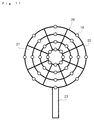
- the support member 20 is composed of a plurality of concentrically disposed circular frames 22 as depicted in Fig. 11
- a configuration wherein the differential microphones 10 are arrayed in a radial pattern one mode of disposition in an array according to the present invention
- the differential microphones 10 provided to the sound source tracking device 1 are merely one example of differential microphones that may be implemented in the present invention.
- the differential microphones 10 of the embodiment were configured with two sound entry ports 141, 142 formed on the same face, and acoustic pressure is applied to both faces 121a, 121b of the diaphragm 121.
- the configuration like that shown in Fig. 12A for example does not form part of the present invention.
- the differential microphone 15 shown in Fig. 12A has one sound entry port 152, 153 formed respectively in the upper face and lower face of an enclosure 151 (multiple sound entry ports may be provided on the upper face and lower face as well), and acoustic pressure is applied to the upper face and lower face of a diaphragm 154.
- the differential microphones 15 are oriented with the principal axis of directionality AX coincident with the direction orthogonal to the diaphragm 154 (see Fig. 12B ).
- the diaphragms 154 are oriented approximately parallel to the surface 20a of the support member 20 as depicted in Fig. 12B .
- differential microphone is a type having two microphones for example, and adapted to output the differential of signals output from the respective microphones as an acoustic signal.
- the differential microphones 10 are configured as MEMS microphones formed using semiconductor manufacturing technology, but no limitation is imposed thereby, and capacitor microphones that use an electret film (ECM) or the like could also be used. Nor are the differential microphones limited to microphones of so-called capacitor type; for example, dynamic type, magnetic type, or piezoelectric type microphones could also be used.
- ECM electret film
- the configuration was one in which the light emitting portions 30 are provided with LEDs of two colors, and the emitted color changes according to the output level (power) of the signal output by the differential microphone 10.
- this configuration is not intended as limiting, and the light emitting portions 30 may instead be configured as single-color LEDs, for a configuration in which the amount of emitted light varies according to the output level of the signal output by the differential microphone 10.
- Such a configuration likewise allows localization to be carried out through visual confirmation of differences in output level of signals output by individual differential microphones.
- Driving of the light emitting portions 30 may be accomplished using analog signals, and a configuration that dispenses with the digitizer 42 (see Fig. 7 ) used in the embodiment shown above would also be acceptable.
- the light emitting portions 30 are composed of LEDs
- the light emitting portions 30 employing LEDs are but one example of light emitting portions in the present invention, and the light emitting portions may be formed with light sources other than LEDs (such as semiconductor lasers for example).
- Fig. 13 a configuration in which, in addition to being disposed in proximity to the differential microphones 10, light emitting portions 30 are disposed in proximity to at least one location between differential microphones 10.
- Fig. 13 is a schematic plan view of the support member 20 viewed from the face thereof on the opposite side from the face thereof where the differential microphones 10 are disposed.
- light emitting portions 30 are also disposed in proximity to medial locations between neighboring differential microphones 10 along the array axes (portions indicated by broken line circles).
- the light emitting portions 30 disposed in proximity to medial locations between neighboring differential microphones 10 may be adapted to emit light according to estimated signal output levels obtained through supplemental processing on the basis of the output levels of signals output from the differential microphones.
- the embodiment shown above is configured with the display portion composed of the light emitting portions 30 and the light emitting portion driving portion 43.
- the display portion could also be a monitor composed of a liquid crystal display, for example.
- processing of signals output by the differential microphones 10 and signal processing for driving the corresponding light emitting portions 30 may be accomplished with a simple configuration. Therefore, an arrangement in which the differential microphones 10 are provided individually with an IC for carrying out signal processing is also acceptable. In this instance the ICs are attached to the support member 20.
- the sound source tracking device of the present invention is readily capable of highly accurate localization, and also affords excellent portability during sound source tracking. Therefore, it is suited to use in various fields where localization is necessary.
Landscapes
- Physics & Mathematics (AREA)
- Engineering & Computer Science (AREA)
- General Physics & Mathematics (AREA)
- Radar, Positioning & Navigation (AREA)
- Remote Sensing (AREA)
- Health & Medical Sciences (AREA)
- Otolaryngology (AREA)
- Acoustics & Sound (AREA)
- Signal Processing (AREA)
- Circuit For Audible Band Transducer (AREA)
- Obtaining Desirable Characteristics In Audible-Bandwidth Transducers (AREA)
- Measurement Of Velocity Or Position Using Acoustic Or Ultrasonic Waves (AREA)
Claims (14)
- Dispositif de suivi de source sonore (1) comprenant :une pluralité de microphones (10) ;un élément de support (20) pour supporter les microphones de la pluralité de microphones (10) de telle sorte que la pluralité de microphones (10) sont disposés en réseau dans un plan donné,caractérisé en ce que
les microphones de la pluralité de microphones (10) sont une pluralité de microphones différentiels bidirectionnels (10), dans lequel les microphones de la pluralité de microphones différentiels (10) sont configurés avec deux ports de son (141, 142) de telle sorte que la pression acoustique est appliquée aux deux faces d'un diaphragme (121), dans lequel les deux ports de son (141, 142) sont pourvus sur le même plan et dans lequel les deux ports de son (141, 142) sont alignés comme axe principal de directionalité (AX) ; et
les microphones de la pluralité de microphones différentiels (10) sont supportés par l'élément de support (20) de telle sorte que l'axe principal (AX) de directionalité de chacun des microphones est essentiellement orthogonal au plan donné, et le plan sur lequel les deux ports de son (141, 142) de chacun des microphones sont pourvus est essentiellement orthogonal au plan donné. - Dispositif de suivi de source sonore (1) selon la revendication 1, dans lequel l'élément de support (20) est composé d'une pluralité de portions en forme de bâton (22) agencées en réseau selon un motif régulier, et comporte une pluralité d'ouvertures (21) qui y sont formées.
- Dispositif de suivi de source sonore (1) selon la revendication 1 ou 2, comprenant en outre :une portion de calcul pour mettre en oeuvre un processus de calcul sur une sortie de signal depuis chaque microphone de la pluralité de microphones différentiels (10) ; etune portion d'affichage qui est adaptée pour produire, sur base de résultats de calcul dans la portion de calcul, un affichage du niveau de sortie de signaux sortis par chaque microphone de la pluralité de microphones différentiels (10).
- Dispositif de suivi de source sonore (1) selon la revendication 3, dans lequel la portion d'affichage est adaptée pour produire un affichage d'un niveau de sortie de signal estimé obtenu sur base des résultats de calcul dans la portion de calcul, pour au moins une position entre des microphones différentiels voisins (10).
- Dispositif de suivi de source sonore (1) selon la revendication 3, dans lequel
la portion d'affichage comprend une pluralité de premières portions d'émission lumineuse (30) ; et
les portions de la pluralité de premières portions d'émission lumineuse (30) sont attachées à l'élément de support (20) de telle sorte que les premières portions d'émission lumineuse (30) sont respectivement disposées à proximité de la pluralité de microphones différentiels (10). - Dispositif de suivi de source sonore (1) selon la revendication 4 ou 5, dans lequel
la portion d'affichage comprend une pluralité de deuxièmes portions d'émission lumineuse ; et
les portions de la pluralité de deuxièmes portions d'émission lumineuse sont attachées à l'élément de support de telle sorte que les deuxièmes portions d'émission lumineuse (30) sont disposées à proximité d'au moins une position entre les microphones différentiels (10). - Dispositif de suivi de source sonore (1) selon la revendication 5 ou 6, dans lequel les premières portions d'émission lumineuse (30), ou les première et deuxième portions d'émission lumineuse, font varier la quantité de lumière émise en fonction du niveau de sortie de signal.
- Dispositif de suivi de source sonore (1) selon la revendication 5 ou 6, dans lequel les premières portions d'émission lumineuse (30), ou les première et deuxième portions d'émission lumineuse, font varier la couleur de la lumière émise en fonction du niveau de sortie de signal.
- Dispositif de suivi de source sonore (1) selon l'une quelconque des revendications 3 à 8, dans lequel la portion de calcul est attachée à l'élément de support (20).
- Dispositif de suivi de source sonore (1) selon l'une quelconque des revendications 1 à 9, dans lequel une portion de saisie (23) est disposée sur l'élément de support (20).
- Dispositif de suivi de source sonore (1) selon la revendication 10, dans lequel la portion de calcul est incorporée dans la portion de saisie (23).
- Dispositif de suivi de source sonore (1) selon l'une quelconque des revendications 1 à 11, dans lequel les microphones de la pluralité de microphones différentiels (10) sont agencés de telle sorte que des microphones différentiels voisins (10) sont espacés de manière équidistante.
- Dispositif de suivi de source sonore selon la revendication 1, dans lequel les microphones différentiels (10) sont disposés en réseau avec les ports de son (141, 142) pointant essentiellement dans une même direction.
- Dispositif de suivi de source sonore selon l'une quelconque des revendications 1 à 13, dans lequel le port de son (141, 142) est un port d'entrée de son.
Applications Claiming Priority (1)
| Application Number | Priority Date | Filing Date | Title |
|---|---|---|---|
| JP2009280115A JP5423370B2 (ja) | 2009-12-10 | 2009-12-10 | 音源探査装置 |
Publications (2)
| Publication Number | Publication Date |
|---|---|
| EP2352309A1 EP2352309A1 (fr) | 2011-08-03 |
| EP2352309B1 true EP2352309B1 (fr) | 2016-03-23 |
Family
ID=43768741
Family Applications (1)
| Application Number | Title | Priority Date | Filing Date |
|---|---|---|---|
| EP10194136.7A Not-in-force EP2352309B1 (fr) | 2009-12-10 | 2010-12-08 | Dispositif de suivi de source sonore |
Country Status (3)
| Country | Link |
|---|---|
| US (1) | US20110164760A1 (fr) |
| EP (1) | EP2352309B1 (fr) |
| JP (1) | JP5423370B2 (fr) |
Families Citing this family (16)
| Publication number | Priority date | Publication date | Assignee | Title |
|---|---|---|---|---|
| US8176789B1 (en) * | 2011-09-07 | 2012-05-15 | Robert Hickling | Three-microphone sound-intensity probe |
| US9460732B2 (en) * | 2013-02-13 | 2016-10-04 | Analog Devices, Inc. | Signal source separation |
| US9420368B2 (en) | 2013-09-24 | 2016-08-16 | Analog Devices, Inc. | Time-frequency directional processing of audio signals |
| US9516412B2 (en) * | 2014-03-28 | 2016-12-06 | Panasonic Intellectual Property Management Co., Ltd. | Directivity control apparatus, directivity control method, storage medium and directivity control system |
| EP3143776B1 (fr) * | 2014-05-12 | 2018-03-07 | TDK Corporation | Ensemble microphone et procédé de fabrication d'un ensemble microphone |
| US10028051B2 (en) | 2015-08-31 | 2018-07-17 | Panasonic Intellectual Property Management Co., Ltd. | Sound source localization apparatus |
| US20170365271A1 (en) | 2016-06-15 | 2017-12-21 | Adam Kupryjanow | Automatic speech recognition de-reverberation |
| KR101949340B1 (ko) * | 2016-11-02 | 2019-02-18 | 단국대학교 산학협력단 | 음원의 발생 위치를 결정하는 방법 및 장치 |
| WO2019189481A1 (fr) * | 2018-03-28 | 2019-10-03 | 日本電産株式会社 | Système d'analyse acoustique |
| US10206036B1 (en) * | 2018-08-06 | 2019-02-12 | Alibaba Group Holding Limited | Method and apparatus for sound source location detection |
| CN108966102B (zh) * | 2018-08-17 | 2024-03-29 | 钰太芯微电子科技(上海)有限公司 | 一种光电微机电系统麦克风及电子设备 |
| KR102477099B1 (ko) * | 2018-08-21 | 2022-12-13 | 삼성전자주식회사 | 소리 방향 탐지 센서 및 이를 포함하는 전자 장치 |
| JP6903621B2 (ja) * | 2018-11-07 | 2021-07-14 | スカパーJsat株式会社 | マイクロフォン |
| KR102216968B1 (ko) * | 2019-09-06 | 2021-02-18 | 주식회사 원더풀플랫폼 | 크래들을 이용한 도우미 시스템 |
| CN115774240A (zh) * | 2022-10-28 | 2023-03-10 | 国网河北省电力有限公司超高压分公司 | 一种平面麦克风传感器阵列及其声源定位方法 |
| JP7699696B1 (ja) | 2024-06-12 | 2025-06-27 | 三菱電機エンジニアリング株式会社 | 音源探査装置 |
Citations (1)
| Publication number | Priority date | Publication date | Assignee | Title |
|---|---|---|---|---|
| EP2007167A2 (fr) * | 2007-06-21 | 2008-12-24 | Funai Electric Advanced Applied Technology Research Institute Inc. | Dispositif d'entrée-sortie vocale et dispositif de communication |
Family Cites Families (33)
| Publication number | Priority date | Publication date | Assignee | Title |
|---|---|---|---|---|
| DE977176C (de) * | 1953-11-12 | 1965-05-20 | Siemens Ag | Empfangsvorrichtung zur Ermittlung der Bewegungsrichtung eines Strahlers beim Durchgang durch eine Ebene im Raum |
| US3480912A (en) * | 1968-05-17 | 1969-11-25 | Peninsula Research & Dev Corp | Sound level visual indicator having control circuits for controlling plural lamps |
| US4424511A (en) * | 1980-10-30 | 1984-01-03 | Alberts Jr Fred L | Noise monitor |
| US4436966A (en) * | 1982-03-15 | 1984-03-13 | Darome, Inc. | Conference microphone unit |
| JPH01113623A (ja) * | 1987-10-27 | 1989-05-02 | Hino Motors Ltd | 騒音測定装置 |
| US5121426A (en) * | 1989-12-22 | 1992-06-09 | At&T Bell Laboratories | Loudspeaking telephone station including directional microphone |
| US5511130A (en) * | 1994-05-04 | 1996-04-23 | At&T Corp. | Single diaphragm second order differential microphone assembly |
| JPH0981066A (ja) * | 1995-09-14 | 1997-03-28 | Toshiba Corp | 表示装置 |
| US6173059B1 (en) * | 1998-04-24 | 2001-01-09 | Gentner Communications Corporation | Teleconferencing system with visual feedback |
| US7142677B2 (en) * | 2001-07-17 | 2006-11-28 | Clarity Technologies, Inc. | Directional sound acquisition |
| GB0121206D0 (en) * | 2001-08-31 | 2001-10-24 | Mitel Knowledge Corp | System and method of indicating and controlling sound pickup direction and location in a teleconferencing system |
| CA2374299A1 (fr) * | 2002-03-01 | 2003-09-01 | Charles Whitman Fox | Reseau modulaire de microphones pour l'enregistrement de son d'ambiance |
| KR100499124B1 (ko) * | 2002-03-27 | 2005-07-04 | 삼성전자주식회사 | 직교 원형 마이크 어레이 시스템 및 이를 이용한 음원의3차원 방향을 검출하는 방법 |
| JP2004032314A (ja) * | 2002-06-25 | 2004-01-29 | Fuji Xerox Co Ltd | マイクロホンアレイ |
| US20040032957A1 (en) * | 2002-08-14 | 2004-02-19 | Mansy Hansen A. | Sensors and sensor assemblies for monitoring biological sounds and electric potentials |
| JP3918730B2 (ja) * | 2002-12-20 | 2007-05-23 | 富士ゼロックス株式会社 | マイクロホンアレイ及び音圧分布解析システム |
| US7054228B1 (en) * | 2003-03-25 | 2006-05-30 | Robert Hickling | Sound source location and quantification using arrays of vector probes |
| JP2005086365A (ja) * | 2003-09-05 | 2005-03-31 | Sony Corp | 通話装置、会議装置および撮像条件調整方法 |
| EP1682856B1 (fr) * | 2003-11-10 | 2014-01-08 | Brüel & Kjaer Sound & Vibration Measurement A/S | Procede de determination d'une pression sonore provenant d'un element de surface d'une surface emettant des sons |
| JP4517838B2 (ja) * | 2004-12-06 | 2010-08-04 | ヤマハ株式会社 | 音声処理装置 |
| KR100963363B1 (ko) * | 2005-02-28 | 2010-06-14 | 후지쯔 가부시끼가이샤 | 수음 장치 |
| EP1867206B1 (fr) * | 2005-03-16 | 2016-05-11 | James Cox | Ensemble de microphones et systeme de traitement numerique des signaux |
| JP2007006253A (ja) | 2005-06-24 | 2007-01-11 | Sony Corp | 信号処理装置、マイクロフォンシステム、話者方向検出方法及び話者方向検出プログラム |
| US7270006B2 (en) * | 2005-07-25 | 2007-09-18 | Sper Scientific Ltd. | Single button operating sound level meter and method therefor |
| US8457962B2 (en) * | 2005-08-05 | 2013-06-04 | Lawrence P. Jones | Remote audio surveillance for detection and analysis of wildlife sounds |
| EP1949750A1 (fr) * | 2005-11-02 | 2008-07-30 | Yamaha Corporation | Appareil emetteur/recepteur de signaux de voix |
| JP4565035B2 (ja) * | 2006-07-04 | 2010-10-20 | 日本ビクター株式会社 | マイクロホン装置 |
| US8194866B2 (en) * | 2007-08-20 | 2012-06-05 | Smith Christopher M | Sound monitoring, data collection and advisory system |
| JP5128919B2 (ja) * | 2007-11-30 | 2013-01-23 | 船井電機株式会社 | マイクロフォンユニット及び音声入力装置 |
| JP4983630B2 (ja) * | 2008-02-05 | 2012-07-25 | ヤマハ株式会社 | 放収音装置 |
| JP5022261B2 (ja) * | 2008-02-08 | 2012-09-12 | 船井電機株式会社 | マイクロホンユニット |
| JP2010034990A (ja) * | 2008-07-30 | 2010-02-12 | Funai Electric Co Ltd | 差動マイクロホンユニット |
| US8923529B2 (en) * | 2008-08-29 | 2014-12-30 | Biamp Systems Corporation | Microphone array system and method for sound acquisition |
-
2009
- 2009-12-10 JP JP2009280115A patent/JP5423370B2/ja not_active Expired - Fee Related
-
2010
- 2010-12-08 EP EP10194136.7A patent/EP2352309B1/fr not_active Not-in-force
- 2010-12-08 US US12/963,033 patent/US20110164760A1/en not_active Abandoned
Patent Citations (1)
| Publication number | Priority date | Publication date | Assignee | Title |
|---|---|---|---|---|
| EP2007167A2 (fr) * | 2007-06-21 | 2008-12-24 | Funai Electric Advanced Applied Technology Research Institute Inc. | Dispositif d'entrée-sortie vocale et dispositif de communication |
Also Published As
| Publication number | Publication date |
|---|---|
| US20110164760A1 (en) | 2011-07-07 |
| EP2352309A1 (fr) | 2011-08-03 |
| JP5423370B2 (ja) | 2014-02-19 |
| JP2011124749A (ja) | 2011-06-23 |
Similar Documents
| Publication | Publication Date | Title |
|---|---|---|
| EP2352309B1 (fr) | Dispositif de suivi de source sonore | |
| EP2746737B1 (fr) | Dispositif de détection acoustique et caméra acoustique utilisant un réseau de microphones mems | |
| Tiete et al. | SoundCompass: a distributed MEMS microphone array-based sensor for sound source localization | |
| Zöller et al. | Active acoustic contact sensing for soft pneumatic actuators | |
| KR101064976B1 (ko) | 음원위치추정시스템 및 이를 구비한 음원에 반응하는 로봇 | |
| US20060004290A1 (en) | Ultrasound transducer with additional sensors | |
| CA2496785A1 (fr) | Systeme de recherche de source sonore | |
| US20100110273A1 (en) | Voice and position localization | |
| US20020149070A1 (en) | MEMS based acoustic array | |
| CN105445735A (zh) | 个人雷达辅助 | |
| CN111615033B (zh) | 发声装置及其驱动方法、显示面板及显示装置 | |
| JPH05142105A (ja) | 材料疲労の位置を特定する装置及び方法 | |
| US7058184B1 (en) | Acoustic measurement method and apparatus | |
| WO2018058937A1 (fr) | Dispositif de guidage pour aveugles monté sur la tête | |
| CN101614803A (zh) | 声音辨位装置及方法 | |
| KR101667276B1 (ko) | 소형 개구 음향 센서를 이용하는 디지털 전사 시스템 | |
| CN119125602A (zh) | 一种视觉仿生触须式水流检测装置及方法 | |
| CN205562027U (zh) | 一种二维矢量场水听器 | |
| EP2425317B1 (fr) | Système de transcription numérique utilisant des détecteurs acoustiques ayant des ouvertures à orientation verticale par rapport à la surface de travail | |
| CN111596262B (zh) | 矢量水听器及基于该矢量水听器的多目标方位估计方法 | |
| JP4484140B2 (ja) | 場の測定システム、波源探査方法、及び波源探査プログラム | |
| JP5532250B2 (ja) | 音の伝搬状態を可視化する装置 | |
| JP2006346105A (ja) | 超音波プローブ及び超音波診断装置 | |
| CN112240996A (zh) | 用于环境噪声的方向识别的方法,控制设备和存储介质 | |
| Ossant et al. | Airborne ultrasonic imaging system for parallelepipedic object localization |
Legal Events
| Date | Code | Title | Description |
|---|---|---|---|
| PUAI | Public reference made under article 153(3) epc to a published international application that has entered the european phase |
Free format text: ORIGINAL CODE: 0009012 |
|
| AK | Designated contracting states |
Kind code of ref document: A1 Designated state(s): AL AT BE BG CH CY CZ DE DK EE ES FI FR GB GR HR HU IE IS IT LI LT LU LV MC MK MT NL NO PL PT RO RS SE SI SK SM TR |
|
| AX | Request for extension of the european patent |
Extension state: BA ME |
|
| 17P | Request for examination filed |
Effective date: 20111209 |
|
| 17Q | First examination report despatched |
Effective date: 20150128 |
|
| GRAP | Despatch of communication of intention to grant a patent |
Free format text: ORIGINAL CODE: EPIDOSNIGR1 |
|
| RIC1 | Information provided on ipc code assigned before grant |
Ipc: H04R 1/40 20060101AFI20150921BHEP Ipc: H04R 29/00 20060101ALN20150921BHEP Ipc: G01H 3/00 20060101ALI20150921BHEP Ipc: G01S 3/808 20060101ALI20150921BHEP Ipc: G01H 3/10 20060101ALI20150921BHEP Ipc: H04R 19/00 20060101ALN20150921BHEP Ipc: G01S 3/80 20060101ALI20150921BHEP Ipc: H04R 3/00 20060101ALI20150921BHEP |
|
| RIC1 | Information provided on ipc code assigned before grant |
Ipc: G01S 3/80 20060101ALI20151001BHEP Ipc: G01H 3/10 20060101ALI20151001BHEP Ipc: G01H 3/00 20060101ALI20151001BHEP Ipc: H04R 29/00 20060101ALN20151001BHEP Ipc: H04R 1/40 20060101AFI20151001BHEP Ipc: H04R 19/00 20060101ALN20151001BHEP Ipc: H04R 3/00 20060101ALI20151001BHEP Ipc: G01S 3/808 20060101ALI20151001BHEP |
|
| INTG | Intention to grant announced |
Effective date: 20151014 |
|
| GRAS | Grant fee paid |
Free format text: ORIGINAL CODE: EPIDOSNIGR3 |
|
| GRAA | (expected) grant |
Free format text: ORIGINAL CODE: 0009210 |
|
| AK | Designated contracting states |
Kind code of ref document: B1 Designated state(s): AL AT BE BG CH CY CZ DE DK EE ES FI FR GB GR HR HU IE IS IT LI LT LU LV MC MK MT NL NO PL PT RO RS SE SI SK SM TR |
|
| REG | Reference to a national code |
Ref country code: GB Ref legal event code: FG4D |
|
| REG | Reference to a national code |
Ref country code: CH Ref legal event code: EP |
|
| REG | Reference to a national code |
Ref country code: AT Ref legal event code: REF Ref document number: 784183 Country of ref document: AT Kind code of ref document: T Effective date: 20160415 |
|
| REG | Reference to a national code |
Ref country code: IE Ref legal event code: FG4D |
|
| REG | Reference to a national code |
Ref country code: DE Ref legal event code: R096 Ref document number: 602010031377 Country of ref document: DE |
|
| REG | Reference to a national code |
Ref country code: LT Ref legal event code: MG4D |
|
| REG | Reference to a national code |
Ref country code: NL Ref legal event code: MP Effective date: 20160323 |
|
| PG25 | Lapsed in a contracting state [announced via postgrant information from national office to epo] |
Ref country code: HR Free format text: LAPSE BECAUSE OF FAILURE TO SUBMIT A TRANSLATION OF THE DESCRIPTION OR TO PAY THE FEE WITHIN THE PRESCRIBED TIME-LIMIT Effective date: 20160323 Ref country code: GR Free format text: LAPSE BECAUSE OF FAILURE TO SUBMIT A TRANSLATION OF THE DESCRIPTION OR TO PAY THE FEE WITHIN THE PRESCRIBED TIME-LIMIT Effective date: 20160624 Ref country code: FI Free format text: LAPSE BECAUSE OF FAILURE TO SUBMIT A TRANSLATION OF THE DESCRIPTION OR TO PAY THE FEE WITHIN THE PRESCRIBED TIME-LIMIT Effective date: 20160323 Ref country code: NO Free format text: LAPSE BECAUSE OF FAILURE TO SUBMIT A TRANSLATION OF THE DESCRIPTION OR TO PAY THE FEE WITHIN THE PRESCRIBED TIME-LIMIT Effective date: 20160623 |
|
| REG | Reference to a national code |
Ref country code: AT Ref legal event code: MK05 Ref document number: 784183 Country of ref document: AT Kind code of ref document: T Effective date: 20160323 |
|
| PG25 | Lapsed in a contracting state [announced via postgrant information from national office to epo] |
Ref country code: LT Free format text: LAPSE BECAUSE OF FAILURE TO SUBMIT A TRANSLATION OF THE DESCRIPTION OR TO PAY THE FEE WITHIN THE PRESCRIBED TIME-LIMIT Effective date: 20160323 Ref country code: NL Free format text: LAPSE BECAUSE OF FAILURE TO SUBMIT A TRANSLATION OF THE DESCRIPTION OR TO PAY THE FEE WITHIN THE PRESCRIBED TIME-LIMIT Effective date: 20160323 Ref country code: SE Free format text: LAPSE BECAUSE OF FAILURE TO SUBMIT A TRANSLATION OF THE DESCRIPTION OR TO PAY THE FEE WITHIN THE PRESCRIBED TIME-LIMIT Effective date: 20160323 Ref country code: LV Free format text: LAPSE BECAUSE OF FAILURE TO SUBMIT A TRANSLATION OF THE DESCRIPTION OR TO PAY THE FEE WITHIN THE PRESCRIBED TIME-LIMIT Effective date: 20160323 Ref country code: RS Free format text: LAPSE BECAUSE OF FAILURE TO SUBMIT A TRANSLATION OF THE DESCRIPTION OR TO PAY THE FEE WITHIN THE PRESCRIBED TIME-LIMIT Effective date: 20160323 |
|
| PG25 | Lapsed in a contracting state [announced via postgrant information from national office to epo] |
Ref country code: EE Free format text: LAPSE BECAUSE OF FAILURE TO SUBMIT A TRANSLATION OF THE DESCRIPTION OR TO PAY THE FEE WITHIN THE PRESCRIBED TIME-LIMIT Effective date: 20160323 Ref country code: IS Free format text: LAPSE BECAUSE OF FAILURE TO SUBMIT A TRANSLATION OF THE DESCRIPTION OR TO PAY THE FEE WITHIN THE PRESCRIBED TIME-LIMIT Effective date: 20160723 Ref country code: PL Free format text: LAPSE BECAUSE OF FAILURE TO SUBMIT A TRANSLATION OF THE DESCRIPTION OR TO PAY THE FEE WITHIN THE PRESCRIBED TIME-LIMIT Effective date: 20160323 |
|
| PG25 | Lapsed in a contracting state [announced via postgrant information from national office to epo] |
Ref country code: SM Free format text: LAPSE BECAUSE OF FAILURE TO SUBMIT A TRANSLATION OF THE DESCRIPTION OR TO PAY THE FEE WITHIN THE PRESCRIBED TIME-LIMIT Effective date: 20160323 Ref country code: RO Free format text: LAPSE BECAUSE OF FAILURE TO SUBMIT A TRANSLATION OF THE DESCRIPTION OR TO PAY THE FEE WITHIN THE PRESCRIBED TIME-LIMIT Effective date: 20160323 Ref country code: SK Free format text: LAPSE BECAUSE OF FAILURE TO SUBMIT A TRANSLATION OF THE DESCRIPTION OR TO PAY THE FEE WITHIN THE PRESCRIBED TIME-LIMIT Effective date: 20160323 Ref country code: ES Free format text: LAPSE BECAUSE OF FAILURE TO SUBMIT A TRANSLATION OF THE DESCRIPTION OR TO PAY THE FEE WITHIN THE PRESCRIBED TIME-LIMIT Effective date: 20160323 Ref country code: PT Free format text: LAPSE BECAUSE OF FAILURE TO SUBMIT A TRANSLATION OF THE DESCRIPTION OR TO PAY THE FEE WITHIN THE PRESCRIBED TIME-LIMIT Effective date: 20160725 Ref country code: CZ Free format text: LAPSE BECAUSE OF FAILURE TO SUBMIT A TRANSLATION OF THE DESCRIPTION OR TO PAY THE FEE WITHIN THE PRESCRIBED TIME-LIMIT Effective date: 20160323 Ref country code: AT Free format text: LAPSE BECAUSE OF FAILURE TO SUBMIT A TRANSLATION OF THE DESCRIPTION OR TO PAY THE FEE WITHIN THE PRESCRIBED TIME-LIMIT Effective date: 20160323 |
|
| PG25 | Lapsed in a contracting state [announced via postgrant information from national office to epo] |
Ref country code: IT Free format text: LAPSE BECAUSE OF FAILURE TO SUBMIT A TRANSLATION OF THE DESCRIPTION OR TO PAY THE FEE WITHIN THE PRESCRIBED TIME-LIMIT Effective date: 20160323 Ref country code: BE Free format text: LAPSE BECAUSE OF FAILURE TO SUBMIT A TRANSLATION OF THE DESCRIPTION OR TO PAY THE FEE WITHIN THE PRESCRIBED TIME-LIMIT Effective date: 20160323 |
|
| REG | Reference to a national code |
Ref country code: DE Ref legal event code: R097 Ref document number: 602010031377 Country of ref document: DE |
|
| PLBE | No opposition filed within time limit |
Free format text: ORIGINAL CODE: 0009261 |
|
| STAA | Information on the status of an ep patent application or granted ep patent |
Free format text: STATUS: NO OPPOSITION FILED WITHIN TIME LIMIT |
|
| PG25 | Lapsed in a contracting state [announced via postgrant information from national office to epo] |
Ref country code: DK Free format text: LAPSE BECAUSE OF FAILURE TO SUBMIT A TRANSLATION OF THE DESCRIPTION OR TO PAY THE FEE WITHIN THE PRESCRIBED TIME-LIMIT Effective date: 20160323 |
|
| PG25 | Lapsed in a contracting state [announced via postgrant information from national office to epo] |
Ref country code: BG Free format text: LAPSE BECAUSE OF FAILURE TO SUBMIT A TRANSLATION OF THE DESCRIPTION OR TO PAY THE FEE WITHIN THE PRESCRIBED TIME-LIMIT Effective date: 20160623 |
|
| 26N | No opposition filed |
Effective date: 20170102 |
|
| PG25 | Lapsed in a contracting state [announced via postgrant information from national office to epo] |
Ref country code: SI Free format text: LAPSE BECAUSE OF FAILURE TO SUBMIT A TRANSLATION OF THE DESCRIPTION OR TO PAY THE FEE WITHIN THE PRESCRIBED TIME-LIMIT Effective date: 20160323 |
|
| REG | Reference to a national code |
Ref country code: DE Ref legal event code: R119 Ref document number: 602010031377 Country of ref document: DE |
|
| REG | Reference to a national code |
Ref country code: CH Ref legal event code: PL |
|
| GBPC | Gb: european patent ceased through non-payment of renewal fee |
Effective date: 20161208 |
|
| PG25 | Lapsed in a contracting state [announced via postgrant information from national office to epo] |
Ref country code: MC Free format text: LAPSE BECAUSE OF FAILURE TO SUBMIT A TRANSLATION OF THE DESCRIPTION OR TO PAY THE FEE WITHIN THE PRESCRIBED TIME-LIMIT Effective date: 20160323 |
|
| REG | Reference to a national code |
Ref country code: FR Ref legal event code: ST Effective date: 20170831 |
|
| REG | Reference to a national code |
Ref country code: IE Ref legal event code: MM4A |
|
| PG25 | Lapsed in a contracting state [announced via postgrant information from national office to epo] |
Ref country code: FR Free format text: LAPSE BECAUSE OF NON-PAYMENT OF DUE FEES Effective date: 20170102 Ref country code: LI Free format text: LAPSE BECAUSE OF NON-PAYMENT OF DUE FEES Effective date: 20161231 Ref country code: CH Free format text: LAPSE BECAUSE OF NON-PAYMENT OF DUE FEES Effective date: 20161231 Ref country code: LU Free format text: LAPSE BECAUSE OF NON-PAYMENT OF DUE FEES Effective date: 20161208 |
|
| PG25 | Lapsed in a contracting state [announced via postgrant information from national office to epo] |
Ref country code: GB Free format text: LAPSE BECAUSE OF NON-PAYMENT OF DUE FEES Effective date: 20161208 Ref country code: IE Free format text: LAPSE BECAUSE OF NON-PAYMENT OF DUE FEES Effective date: 20161208 Ref country code: DE Free format text: LAPSE BECAUSE OF NON-PAYMENT OF DUE FEES Effective date: 20170701 |
|
| PG25 | Lapsed in a contracting state [announced via postgrant information from national office to epo] |
Ref country code: CY Free format text: LAPSE BECAUSE OF FAILURE TO SUBMIT A TRANSLATION OF THE DESCRIPTION OR TO PAY THE FEE WITHIN THE PRESCRIBED TIME-LIMIT Effective date: 20160323 Ref country code: HU Free format text: LAPSE BECAUSE OF FAILURE TO SUBMIT A TRANSLATION OF THE DESCRIPTION OR TO PAY THE FEE WITHIN THE PRESCRIBED TIME-LIMIT; INVALID AB INITIO Effective date: 20101208 |
|
| PG25 | Lapsed in a contracting state [announced via postgrant information from national office to epo] |
Ref country code: MK Free format text: LAPSE BECAUSE OF FAILURE TO SUBMIT A TRANSLATION OF THE DESCRIPTION OR TO PAY THE FEE WITHIN THE PRESCRIBED TIME-LIMIT Effective date: 20160323 Ref country code: TR Free format text: LAPSE BECAUSE OF FAILURE TO SUBMIT A TRANSLATION OF THE DESCRIPTION OR TO PAY THE FEE WITHIN THE PRESCRIBED TIME-LIMIT Effective date: 20160323 |
|
| PG25 | Lapsed in a contracting state [announced via postgrant information from national office to epo] |
Ref country code: MT Free format text: LAPSE BECAUSE OF NON-PAYMENT OF DUE FEES Effective date: 20161208 |
|
| PG25 | Lapsed in a contracting state [announced via postgrant information from national office to epo] |
Ref country code: AL Free format text: LAPSE BECAUSE OF FAILURE TO SUBMIT A TRANSLATION OF THE DESCRIPTION OR TO PAY THE FEE WITHIN THE PRESCRIBED TIME-LIMIT Effective date: 20160323 |