EP2353441A1 - Armature pour une armoire de coin - Google Patents
Armature pour une armoire de coin Download PDFInfo
- Publication number
- EP2353441A1 EP2353441A1 EP11000794A EP11000794A EP2353441A1 EP 2353441 A1 EP2353441 A1 EP 2353441A1 EP 11000794 A EP11000794 A EP 11000794A EP 11000794 A EP11000794 A EP 11000794A EP 2353441 A1 EP2353441 A1 EP 2353441A1
- Authority
- EP
- European Patent Office
- Prior art keywords
- lever
- tray
- fitting arrangement
- arrangement according
- damping
- Prior art date
- Legal status (The legal status is an assumption and is not a legal conclusion. Google has not performed a legal analysis and makes no representation as to the accuracy of the status listed.)
- Granted
Links
Images


Classifications
-
- A—HUMAN NECESSITIES
- A47—FURNITURE; DOMESTIC ARTICLES OR APPLIANCES; COFFEE MILLS; SPICE MILLS; SUCTION CLEANERS IN GENERAL
- A47B—TABLES; DESKS; OFFICE FURNITURE; CABINETS; DRAWERS; GENERAL DETAILS OF FURNITURE
- A47B49/00—Revolving cabinets or racks; Cabinets or racks with revolving parts
- A47B49/004—Cabinets with compartments provided with trays revolving on a vertical axis
- A47B49/006—Corner cabinets
-
- A—HUMAN NECESSITIES
- A47—FURNITURE; DOMESTIC ARTICLES OR APPLIANCES; COFFEE MILLS; SPICE MILLS; SUCTION CLEANERS IN GENERAL
- A47B—TABLES; DESKS; OFFICE FURNITURE; CABINETS; DRAWERS; GENERAL DETAILS OF FURNITURE
- A47B81/00—Cabinets or racks specially adapted for other particular purposes, e.g. for storing guns or skis
- A47B81/002—Corner cabinets; Cabinets designed for being placed in a corner or a niche
Definitions
- the invention relates to a fitting arrangement for a corner cabinet, in particular causaleck O, wherein the corner cabinet has a cabinet body and accessible via a corner door interior in which at least one tray by means of at least two relatively movable lever between an inner position and an outer position in which the tray at least partially protruding beyond a plane of a door opening, is movably guided, and with a damping device for damping the Tablarterrorism when retracting to the inner position and / or extending into the outer position.
- a fitting of this kind is for example from the EP 1 925 238 B1 known, which has two lever means, one of which is designed such that the distance between its bearing point and a stationary pivot axis in the Tablarterrorism between the inner and outer position changes.
- a damping device in the form of a damping cylinder, which on the one hand on a lever of the lever means arranged relatively immovable to this and on the other hand may be coupled in motion with a bearing point, with respect to which the variable-length lever changes. This is achieved by this variable-length lever on a control cam with eccentric curve and dead center expires, so that the lever length shortens during the Tablar Gayieri from the inner to the outer position and extended. With this shortening and lengthening of the lever lever length, the damper is also active.
- the damper is thus active over the entire pivoting path of the tray between the inner and outer position, which is not absolutely necessary.
- the object of the invention is to provide a fitting arrangement of the aforementioned type, with which can be realized with simple means damping the retraction movement of the tray in the inner position as well as a damping of the extension movement in the outer position.
- the fitting arrangement according to the invention is characterized in that the damping device comprises a shock absorber, which is arranged such that it dampens both when approaching the inner position and when approaching the outer position and in at least one lying between the inner and the outer position Intermediate position is ineffective.
- shock absorber cushioning of the two end positions of the tray can be realized.
- the shock absorber thus dampens both the retraction movement of the tray in its inner position and the extension movement in the outer position. This can prevent a hard stop of the tray in its two end positions. Since there is a pure cushioning, it is not necessary that the shock absorber over the entire pivoting of the tray between the inner and the outer position is active, but he is active, for example, only over a relatively short damping distance when approaching the inner position and over a relatively short attenuation distance when approaching the exhibition, while he is inactive over the rest of the pivoting path. Since the shock absorber takes over the damping of both end positions, it is not necessary to provide a separate shock absorber for each end position.
- the shock absorber is arranged on one of the two levers of the fitting arrangement.
- the shock absorber is arranged on another fitting component of the fitting or on the Eck Heperipherie, in the latter case would have to come into contact with the shock absorber by the stationary arrangement of the shock absorber two different sections of the fitting.
- the arranged on the lever shock absorber acts with at least two arranged at different positions on the other lever stop surfaces together such that when approaching the inner position of a damping stop of shock absorbers and a stop surface and approaching the outer position of a damping stop of the shock absorber and the other stop surface is present.
- one or the other abutment surface can therefore abut against the shock absorber.
- the one abutment surface in the transverse direction of the lever is arranged on the outside than the other abutment surface.
- the abutment surface arranged further outward in the transverse direction of the lever can, for example, be on one end face a mounted on the lever stop member sit.
- the shock absorber is formed by a damping cylinder, with a cylinder housing in which a damping piston is guided linearly displaceable.
- damper types for example a rubber-elastic buffer, which is elastically compressed when striking one of the stop surfaces and thereby produces a damping effect.
- a damping spring would be conceivable.
- the fitting at least one on the one hand about a fixed pivot axis and on the other hand on a tablarfore bearing axis pivotally mounted on the tray supporting arm for Tablarabstützung and a control device for controlling the Tablarterrorism in the pivot plane between the inner and outer position.
- the control device may have two control levers, which are each mounted on the one hand about a stationary pivot axis and on the other hand about a tablarfeste bearing axis with respect to this rotatable and immovable.
- the two stationary pivot axes can be arranged adjacent to one another or coincide.
- a connecting member for connecting the two control levers is provided, which receives the two tablarfesten bearing axes of the control lever and in turn attached to the tray.
- one of the two control levers at the same time forms the support arm and is in the form of a combined control / support lever, which has a greater bending stiffness relative to the other control lever perpendicular to the pivot plane.
- shock absorber on the control / support lever and the two stop surfaces are arranged on the control lever.
- the invention further comprises a corner cabinet with the features of independent claim 14.
- the corner cabinet according to the invention is characterized in that the damping device comprises a shock absorber which is arranged such that it dampens both when approaching the inner position and when approaching the outer position and lying in at least one between the inner and the outer position Intermediate position is ineffective.
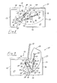
- FIGS. 1 and 2 show a first embodiment of the invention Eck Os 11 and the built-in inventive fitting 12.
- the corner cabinet 11 has a cabinet body 13, which is shown by way of example with a rectangular plan.
- the cabinet body 13 in turn consists of a rear wall 14, two side walls 15, 16 and a front side 17, which in turn is subdivided into a front wall 18 and a corner cabinet door 19 arranged adjacent thereto
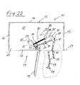
- FIGS. 21 to 23 shows the corner cabinet door 19 seen from the front on the right side of the front 17 and the front wall 18 is arranged correspondingly on the left side of the front 17.
- the extension movement of the tray thus takes place in a clockwise direction.
- the corner cabinet door 19 can alternatively also be arranged on the left side of the front side 17 of the corner cabinet 11, so that the extension movement of the shelf from the inside position takes place by pivoting in the counterclockwise direction.
- Front wall 18 and corner door 19 occupy the front 17 in approximately equal parts.
- the rectangular cabinet body 13 defines a correspondingly rectangular interior 21, which is accessible in about half of the corner cabinet door 19.
- the interior of the corner cupboard 11 is at least one tray 22, which is housed by means of the fitting 12 between an inner position in which the tray 22 is completely housed in the interior 21, and an outer position in which the tray 22 at least partially over a plane 23 of a door opening the corner cupboard 11 protrudes, is movably controlled in a pivoting plane.
- a single tray 22 is shown here.
- two or more superimposed shelves 22 are arranged.
- the tray 22 is exemplified in one-piece embodiment.
- the floor plan of the tray 22 is exemplified in the form of a kidney.
- the tray 22 has on its front wall 18 facing the inside of a sidecut 24 to allow a comfortable swinging out of the interior 21 and pivoting into the interior 21 without the tray 22 abuts the front wall 18 and remains hanging.
- the fitting 12 has at least one pivotally mounted on the one hand to a fixed in the installed state of the tray 22 pivot axis 25 and on the other hand mounted on a tablarfesten bearing axis 26 pivotally mounted on the associated tray arm for Tablarabstützung and a control device for controlling the Tablarterrorism in the pivot plane between the indoor and the external position.
- the control device further has two control levers, one of which also forms the support arm and is designed in the form of a combined control / support lever 27, which has a greater bending stiffness relative to the other control lever 28 at right angles to the pivot plane.
- the control / support lever thus performs a double function, so he controls the tablet movement between the inner and outer position as a control lever and supports the tray 22 as a support arm.
- the control lever 28 is also mounted on the one hand to a fixed pivot axis 29 and on the other hand to a tablarfeste bearing axis 30 with respect to this rotatable and immovable.
- the control / support lever 27 is mounted about its tablarfeste bearing axis 26 with respect to this rotatable and immovable.
- the two stationary pivot axes 25, 29 of the control / support lever 27 and the control lever 28 are adjacent to each other or fall together, wherein in the illustrated embodiments, by way of example, an adjacent arrangement of the stationary pivot axes 25, 29 is shown.
- this is formed by a metal square tube.
- a bearing sleeve 31 is fixed to the stationary end of this square tube, in particular welded.
- a bearing pin for example in Inserted form of a rivet, which in turn is attached to a U-shaped, the bearing sleeve 31 receiving bearing portion 33 on a clamping piece 34 described in more detail below.
- the bearing pin forms the stationary pivot axis 25 about which the control / support lever 27 is pivotally mounted.
- a further bearing sleeve 35 is fastened in a similar manner, in particular welded.
- the bearing sleeve 35 is penetrated by a bearing pin, which in turn is mounted on a connecting member 36 described in more detail below.
- the bearing pin thus forms the tablarfeste bearing axis 26 of the control / support lever 27th
- control lever 28 is formed by a flat iron bar.
- control lever 18 has at both opposite ends in each case a particular circular passage opening 37, in each of which a bearing pin, for example in the form of a rivet, is inserted therethrough.
- the one end of the control lever 28 is in turn mounted on the clamping piece 34, wherein the bearing pin forms the stationary pivot axis 29 of the control lever 28.
- the opposite end is mounted by means of the other bearing pin on the connecting member 36, said bearing pin forms the tablarfeste bearing axis 30 of the control lever 28.
- both stationary pivot axes 25, 29 of the control / support lever 27 and the control lever 28 are arranged on the clamping piece 34, wherein according to the described embodiments, the fixed pivot axis 25 of the control / support lever 27 closer to a longitudinal axis 38 of a support column described in more detail below 39th is stored as the stationary pivot axis 29 of the control lever 28.
- the lever length of the control / support lever 27 is greater than the lever length of the control lever 28, so that the tablarfeste bearing axis 26 of the control / support lever 27 describes a circular arc with a larger radius than the tablarfeste bearing axis 30 of the control lever 28. This results in a relative movement of control / support lever 27 and control lever 28 in the Tablarterrorism between the inner and the external position.
- both tablarfesten bearing shafts 26, 30 of the control / support lever 27 and the control lever 28 are arranged on a connecting member 36 which thus connects these two tablarfesten bearing shafts 26, 30 together.
- the connecting member 36 has an axle carrier 40, on which the two tablarfesten bearing shafts 26, 30 are mounted in the previously described manner.
- the axle carrier 40 is designed yoke-like and has a plate-like first stub axle 41a and a plate-like second stub axle 41b extending parallel thereto, which are held at a distance from each other via two spacers 42 in the form of material webs. Between the two stub axles 41a, 41b is located on the control / support lever 27 end side bearing sleeve 31. In contrast, the control lever 28 is mounted only on one of the two stub axles 41a, 41b by means of the tablarfeste bearing axis 30 forming the bearing pin.
- the connecting member 36 also has an elongated support arm 43, which is also designed as a square tube.
- Support arm 43 and axle carrier 40 are rigidly connected to each other, for example, can be welded together.
- the most rigid bearing axes 26, 30 on the axle support 40 form a connecting line 44, which runs at an obtuse angle to a longitudinal axis 45 of the support arm 43 (FIG. FIG. 8 ).
- the axle 40 In the attached state of the fitting 12th on the tray bottom 46 of the tray 22 is the axle 40 with the two tablarfesten bearing axes 26, 30 in the one, formed by a central transverse axis 47 tray half 48, while the support arm 43 projects into the other of the two tray halves 48.
- the support arm 43 exercises next to the control / support lever 27 a support function for supporting the tray 22. It prevents the tray 22 is supported only on a tray half 48, which could result in instabilities, especially when standing on the tray items. In this case, a large moment would be exerted on the attachment between the axle 40 and the tray, which could lead to a release of the axle carrier 40 from the tray 22.
- the support arm 43 On the support arm 43 at least one fastening tab 49 is provided, via which the support arm 43 can be attached to the tray bottom 46.
- the mounting tab 49 is located on the support arm end, which is opposite to the axle support 40.
- the corner cupboard 11 further has the already mentioned supporting column 39 with a longitudinal axis 38.
- the support column 39 is fastened to the cabinet bottom 20 via a bearing plate 50 and is free in the cabinet body 13, that is not with the side walls 15, 16 and front wall 18 and rear wall 14 connected.
- a further bearing plate 51 is attached, via which the support column 39 is mounted on a cabinet cover (not shown).
- the support column 39 is designed as a telescopic column and has for this purpose a column base 52 and a linearly displaceable in the column base 52 mounted telescope part 53. The telescoping of the support column 39 allows their adaptation to different Eck O cannot be used.
- the fitting 12 is fixed by means of a fastening device to the support column 39.
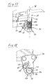
- a fastening device includes the aforementioned clamping piece 34 or bearing element has the clamping means which between a fitting 12 to the support column 39 at the desired height relative to the support column 39 immovably clamped clamping position 54 and a continuous height adjustment of the fitting along the support column 39 enabling release position 55 adjustable are.
- the base body 56 has a base body 56 and two relatively movable jaws 57, 58, with which the associated support column 39 can at least partially surround.
- the U-shaped bearing portion 33 On the base body 56 is the U-shaped bearing portion 33, in which the bearing sleeve 31 of the control / support lever 27 is received, and by means of the stationary pivot axis 25 forming the bearing pin is pivotally mounted.
- One of the legs of the bearing part 33 is designed plate-like and has the passage opening 37, on which by means of the stationary pivot axis 29 forming bearing pin of the control lever 28 is pivotally mounted. It is possible that this plate-like leg has a plurality of such passage openings, so that the stationary pivot axis 29 can be implemented, whereby the pivot radius of the control lever 28 and its position to the control / support lever 27 can be changed.
- one of the two clamping jaws 57 is thus arranged so as to be immovable on the main body 56.
- FIGS. 13 to 16 show a first embodiment of the clamping piece 34 according to the rigid jaw 57 like a hook is designed.
- the second jaw 58 is movably arranged relative to the rigid jaw 57, with the two jaws in the in FIG. 15 or 16 shown release position 55 define an insertion opening 59, with which the clamping piece 34 can be attached laterally to the support sleeve 39, so that the two jaws 57, 58 surround the circumference of the support column 39 partially.
- this insertion opening 59 is narrowed so far that removal of the clamping piece 34 obliquely to the longitudinal axis 38 of the support column 39 is no longer possible and also a clamping of the clamping piece 54 is present on the support column 39, so that this is fixed relative to the support column 39 immovable , Conveniently, the clamping of the clamping piece 34 is carried on the column bottom 52 of the support column 39th
- the movable second jaw 58 is mounted according to the first embodiment by means of guide means in the axial direction to the longitudinal axis 38 of the support column 39 linearly displaceable, wherein at the same time an axially aligned clamping surface of the jaw 58 in the radial direction inwardly to the rigid first jaw is to be displaced.
- the movable jaw 58 has two jaw members 61a, 61b, which are mounted relative to each other in the axial direction to the longitudinal axis 38 of the support column 39 movable relative to each other on the base body 56 of the clamping piece 34, wherein in a Auffactzu movement a displacement of the clamping surfaces on the jaw members 61a, 61b takes place radially inward.
- guide bevels 62a, 62b are formed, which are part of the guide means.
- the guide slopes 62a, 62b act with a Sliding surface 63 together, which is formed by a substantially parallel to the longitudinal axis of the support column 39 aligned wall on the base body 56.
- the guide bevels 62a, 62b of the jaw members 61a, 61b are inclined towards each other, ie when the jaw members 61a, 61b move together, an ever-increasing cross-section of the jaw members 61a, 61b slides on the sliding face 63, whereby the clamping surfaces 60a, 60b move radially inside to the first jaw 57 to be moved.
- adjusting means in the form of an adjusting screw 64 passing through the two jaw members 61a, 61b are used FIG. 15 shown, the adjusting screw 64 is additionally stored in a bearing web 65 of the body.
- the two jaws 57, 58 are first brought into the release position 55, wherein the two jaw members 61a, 61b are moved away from each other. This can be done by unscrewing the screw 34. This results in an insertion opening 59, whose cross section is larger than the cross section of the support column 39, so that the clamping piece 34 can be attached laterally to the support column 39. After setting the screw 64 is screwed again, whereby the two jaw members 61a, 61b are moved towards each other.
- FIGS. 17 to 20 show a second embodiment of the clamping piece 34.
- a rigid, fixed first jaw 57 and a relatively movable second jaw 58 is provided for this purpose.
- the rigid jaw 57 has a larger jaw height than the movable jaw 58.
- the movable second jaw 58 is pivotally mounted by means of pivot means 66 about a jaw pivot axis 67 on the base body 56 of the clamping piece 34.
- the pivot means are configured in a similar manner as in the pivotable mounting of the control / support lever 27 or the control lever 28.
- the pivoting jaw 58 is mounted for this purpose in a U-shaped bearing mount, wherein a pivot bearing pin through both the bearing receiving limiting bearing leg 68a, 68b and the jaw 58 is passed.
- locking means are provided in the form of a locking screw, which is preferably in the transverse direction to the jaw pivot axis 67 aligned both jaws 57, 58 passes and mounted on the rigid jaw 58.
- the two clamping jaws 57, 58 are first brought into the release position 55 by unscrewing the locking screw 69. This creates an in FIG. 19 or 20 shown insertion opening 59 whose cross section is greater than the cross section or diameter of the support column 39, so that the clamping piece 34 can be attached laterally to the support column. If the desired altitude of the clamping piece 34 is reached on the support column 39, the locking screw 69 is screwed, whereby the pivoting jaw 58 is pivoted to the rigid clamping jaw 57, until they finally with clamping force on the outside of the support column 39th pushes, whereby a clamping of the clamping piece on the support column 39 is formed.
- the clamping piece 34 can be infinitely adjustable in height at any point along the support column, in principle also be clamped to the telescope part 53.
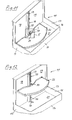
- the fitting 12 is to be attached to the shelf bottom 46 of the tray 22.
- mounting interfaces 70 are formed on the tray bottom 46, which serve for fastening of the fitting 12 by means of the fastening interfaces 70 corresponding fitting-side interface means 71.
- a plurality of fastening interfaces 70 form an interface pattern 72, which is designed such that the fitting 12 can be fastened in two different fastening positions on the shelf 22, so that depending on the predetermined fastening position clockwise or alternatively counterclockwise from the inner to the outer position is pivotable.
- the attachment interfaces 70 are configured as attachment holes in which interface means in the form of fasteners, such as screws, rivets or the like, which are previously passed through corresponding through holes in the fitting 12, can be fixed.
- the interface means 71 are formed by the attached to the support arm 43 mounting tab 49, the two through holes for Carrying out of fasteners in the form of mounting screws, which in turn are fixed in the corresponding mounting interfaces 70 on the tray bottom 46.
- the interface means 71 still include the bearing pin, which forms the most rigid bearing axis 26 of the control / support lever 27. This protrudes through the two stub axles 41a, 41b of the axle carrier 40 and projects upwards so that it can be fixed in the corresponding attachment interface 70.
- the bearing pin that forms the tabletopest bearing axis 30 of the control lever 28 also belongs to the interface means 71. This is guided through a passage opening formed in both stub axles 41a, 41b and protrudes from the top side of the axle carrier 40, so that it engages in its corresponding attachment interface 70 the tray bottom 46 can be inserted and fixed there.
- FIG. 2 shows the interface pattern 72 according to the first embodiment distributed over a large area on the tray bottom 46.
- the half of the mounting interfaces 70 of this interface pattern is located on one tray half 48, while the other half is located on the other tray half.
- a center longitudinal axis 73 is defined, the center longitudinal axis being the X axis and the center transverse axis being the Y axis, the tray 22 is divided into four quadrants the attachment interfaces of this interface pattern 72 are then distributed over all four quadrants.
- four different interface groups 74a, 74b, 74c, 74d, each with two attachment interfaces 70, are provided here.
- the interface groups 74a-d are here mirror-symmetrical to the Y-axis in an exemplary manner.
- Two of the interface groups 74a, 74c are located in the region of the rear edge of the tray, wherein the two attachment interfaces 70 of these interface groups 74a, 74c are arranged one behind the other in the X direction.
- the two other interface groups 74b, 74d are located approximately halfway between the outer side edge of the tray 22 and the Y-axis, with the mounting interfaces 70 of these interface groups 74b, 74d arranged one behind the other in the Y direction.
- the support arm 43 When mounting the fitting 12 according to the first embodiment, the support arm 43 is attached with its fastening tab on the aligned in the Y direction interface group 74b on one tray half 48 and fastened by means of the fastening screws.
- the axle carrier 40 with its bearing pin or bearing pin is attached to the aligned in the X direction interface group 74c on the other tray half and fastened there. This attachment results in a tabla movement according to the FIGS. 21 to 23 , The corner cabinet door 19 is thus seen from the front on the right side and the tray 22 pivots clockwise out of the corner cabinet 11 out.
- the fitting 12 and thus the tray 22 in opposite directions, ie swing out of the interior 21 in the counterclockwise direction.
- the corner cabinet door 11 would then be arranged on the left side.
- the fitting 12 is this folded over by 180 ° and the mounting bracket 49 on the support arm 43 is at the other attached to opposite sides of the support arm 43.
- the support arm 43 with its fastening tab 49 then protrudes into the tray half 48, in which the axle carrier 40 was placed in the other fastening position, while the axle carrier 40 now projects into the tray half 48 in which the support arm 43 with its fastening tab 49 was previously positioned ,
- the fastening tab 49 is then fastened again to the Y-directional interface group 74d with the aid of the fastening screws, while the axle support 40 with the bearing bolts or pins is then fastened to the other panel half 48 in the X direction aligned interface group 74a is attached.
- the tray 22 can thus swing out of the interior 21 either left or right as needed.
- FIGS. 4 and 5 show a second embodiment of the fitting 12 according to the invention, which differs from the first embodiment described above in that the interface pattern 72 is configured differently and also other interface means 71 are used.
- the mounting interfaces 70 are in all four defined by the X and Y axis quadrants on the tray bottom 46. In contrast to the aforementioned embodiment, however, all mounting interfaces 70 are used here in two different mounting positions of the fitting 12 through the associated interface means. By way of example, four fastening interfaces 70 are provided here.
- the interface means 71 comprise an adapter plate 75 which is releasably secured to the top of the square tube-like support arm 43.
- the adapter plate 75 has through holes 76, for example, corresponding to the number of mounting interfaces 70 four in number. Fastening elements, for example fixing screws, are inserted through the through-holes 76 and fixed in the corresponding fastening interfaces 70 on the tray underside 46.
- On the adapter plate 75 are expediently in the longitudinal direction between two through holes 76 centering in the form of upwardly above the top of the adapter plate 75 projecting centering 77, which in corresponding centering holes 78 on the tray bottom 46, which expediently also in the X direction between two mounting interfaces 70th are arranged, can be introduced.
- the adapter plate can position accurately positioned, whereby the aligned position between the through holes 76 on the adapter plate 75 and the mounting interfaces 70 is automatically reached.
- the second embodiment is suitable in a simple manner for an opposing pivoting out of the tray 22 from the interior 21.
- the fitting 12 is again folded over by 180 ° and the adapter plate 75 attached to the opposite side of the support arm 43.
- again all mounting interfaces 70 are used and the adapter plate 75 is attached to the tray bottom 46 at the same location as before.
- the tray 22 can be swung out to the left or right as needed, with the corner cabinet door then being located either on the left or right side.
- FIGS. 5 to 7 show further embodiments of interface patterns 72, different from those described above Differentiate between interface patterns.
- Tabla shown are arranged on the tray bottom mounting interfaces 70, for example, ten in number, which are arranged mirror-symmetrically to the X-axis.
- FIG. 6 shows a variant of the interface pattern 72 of FIG. 5
- the mounting interfaces 70 are aligned both mirror-symmetrical to the X-axis and mirror-symmetrical to the Y-axis.
- FIG. 7 a further variant in which the attachment interfaces, for example, also ten in number, are aligned mirror-symmetrically to the Y-axis.
- the fitting 12 also has an entry and exit device 79 to support the retraction and extension of the tray in the indoor and outdoor position.
- the entry and exit device 79 has a spring unit 80, which is mounted on the one hand at a stationary spring bearing 81 and the other on a movable in the Tablarterrorism movable bearing 82 such that on the fitting 12, a retraction assisting torque in the direction of the inner position and after exceeding a dead center, the outward movement supporting torque is exerted in the direction of the outer position.
- the spring unit 18 is formed by a tension spring in the form of a helical tension spring.
- the stationary spring-bearing 81 is located on the clamping piece 34 and that on the elongated plate-like leg on which the stationary pivot axis 29 of the control lever 28 is seated.
- the moving in the Tablarterrorism bearing 82 is located on the control lever 28, in particular approximately in the middle between the fixed pivot axis 29 and the tablarfesten bearing axis 30th
- the fixed pivot axis and the movable bearing 82 of the spring on the control lever 28 define a straight line with respect to which the fixed spring bearing 81 in the support of the retraction on one side and in supporting the extension movement on the other side.
- the stationary pivot axis 28 and the fixed spring bearing 81 are spaced from each other and that on one side by the fixed pivot axis of the control lever 28 and the movable bearing point the spring unit 80 formed straight lines.
- a torque is applied counterclockwise to the control lever 28 and thereby to the tray 22, so that the tray 22 is held by the spring unit 80 defined in the inner position. If the tray 22 is now pivoted out of the interior 21 in a clockwise direction, this force must first be overcome in the retraction direction in order to pivot the tray 22. When swinging out the tray 22 then reaches an intermediate position by the stationary pivot axis 29 of the control lever 28 and the stationary spring bearing 81 are in line, so that no torque is applied.
- the damping device 83 for damping the Tablarterrorism when retracting to the inner position and / or extending into the outer position.
- the damping device 83 has a shock absorber 84, which is arranged such that it damps both when approaching the inner position and when approaching the outer position and is ineffective in at least one intermediate position between the inner and the outer position.
- the shock absorber 84 is in accordance with FIGS. 8 to 10 shown in exemplary arrangement on the control / support lever 27. There it sits approximately in the middle between the stationary pivot axis 25 and the tablarfesten pivot axis 26 of the control / support lever 27.
- the shock absorber 84 is formed by a damping cylinder, with a cylinder housing 85 in which a damping piston 86 is guided linearly displaceable.
- On the control lever 28 are two arranged at different positions stop surfaces 87a, 87b, which cooperate with the damping piston 86 such that when approaching the inner position of a damping stop of shock absorber 84 and a stop surface 87a and when approaching the outer position of a damping stop of shock absorbers 84th and the other abutment surface 87b is present.
- the one and the same shock absorber 84 thus dampens both when approaching the inner position and when approaching the outer position.
- the two end positions of the tray 22, ie the inner and the outer position, are damped.
- the fitting 12 and the tray 22 are thus initially in the in FIG. 8
- the stop surface 87a which is formed by the outer contour of the control lever 28, presses on the damping piston 86 of the shock absorber 84. If the tray then, for example, as in FIG. 9 shown pivoted out of the corner cabinet 11 in the clockwise direction, so move control / support lever 27 and control lever 28 relative to each other, whereby the damping piston 86 out of contact with the stop surface 87a, whereby the shock absorber 84 is ineffective. If the tray is now pivoted further into the outward position, the damping piston 86 comes into contact with the other stop surface 87b formed on the stop member 88 as it approaches this outward position, thus damping the retraction into the outward position.
Landscapes
- Drawers Of Furniture (AREA)
- Pivots And Pivotal Connections (AREA)
Applications Claiming Priority (1)
| Application Number | Priority Date | Filing Date | Title |
|---|---|---|---|
| DE202010002232U DE202010002232U1 (de) | 2010-02-05 | 2010-02-05 | Beschlaganordnung für einen Eckschrank |
Publications (2)
| Publication Number | Publication Date |
|---|---|
| EP2353441A1 true EP2353441A1 (fr) | 2011-08-10 |
| EP2353441B1 EP2353441B1 (fr) | 2017-08-16 |
Family
ID=42194596
Family Applications (1)
| Application Number | Title | Priority Date | Filing Date |
|---|---|---|---|
| EP11000794.5A Active EP2353441B1 (fr) | 2010-02-05 | 2011-02-02 | Armature pour une armoire de coin |
Country Status (5)
| Country | Link |
|---|---|
| EP (1) | EP2353441B1 (fr) |
| DE (1) | DE202010002232U1 (fr) |
| DK (1) | DK2353441T3 (fr) |
| ES (1) | ES2645208T3 (fr) |
| NO (1) | NO2353441T3 (fr) |
Cited By (2)
| Publication number | Priority date | Publication date | Assignee | Title |
|---|---|---|---|---|
| EP3087866A1 (fr) * | 2015-04-30 | 2016-11-02 | Vauth-Sagel Holding GmbH & Co. KG | Armature pour une armoire angulaire et armoire angulaire dotée d'une armature |
| US12478177B2 (en) * | 2021-09-10 | 2025-11-25 | Ninkaplast Gmbh | Pivot and pull-out fitting for a corner cabinet |
Families Citing this family (4)
| Publication number | Priority date | Publication date | Assignee | Title |
|---|---|---|---|---|
| DE202010014343U1 (de) * | 2010-10-18 | 2010-12-30 | Heinrich J. Kesseböhmer KG | Beschlag für Möbel oder dergleichen |
| US9119470B2 (en) | 2011-05-23 | 2015-09-01 | Kesseböhmer Holding e.K. | Fitting for corner cabinets and pull-in device for said type of fitting |
| DE202015101210U1 (de) * | 2015-03-10 | 2016-06-14 | Hetal-Werke Franz Hettich Gmbh & Co. Kg | Vorrichtung zur Abstützung eines Tragbodens, Schwenkeinrichtung für ein Eckschrank-Möbel und Tragboden |
| DE202015102233U1 (de) * | 2015-05-04 | 2016-08-05 | Hetal-Werke Franz Hettich Gmbh & Co. Kg | Schwenkeinrichtung für einen Tablarhalter eines Eckschrank-Möbels |
Citations (4)
| Publication number | Priority date | Publication date | Assignee | Title |
|---|---|---|---|---|
| DE202004011200U1 (de) * | 2004-07-16 | 2005-12-01 | Heinrich J. Kesseböhmer KG | Eckschrank, insbesondere Kücheneckschrank |
| EP1925237A2 (fr) * | 2006-11-27 | 2008-05-28 | Hetal-Werke Franz Hettich GmbH & Co. KG | Armature pour une armoire angulaire et armoire angulaire |
| EP1925239A1 (fr) * | 2006-11-27 | 2008-05-28 | Hetal-Werke Franz Hettich GmbH & Co. KG | Armature pour une armoire de coin et armoire de coin |
| EP1925238A1 (fr) * | 2006-11-27 | 2008-05-28 | Hetal-Werke Franz Hettich GmbH & Co. KG | Armature pour une armoire angulaire et armoire angulaire |
-
2010
- 2010-02-05 DE DE202010002232U patent/DE202010002232U1/de not_active Expired - Lifetime
-
2011
- 2011-02-02 NO NO11000794A patent/NO2353441T3/no unknown
- 2011-02-02 EP EP11000794.5A patent/EP2353441B1/fr active Active
- 2011-02-02 ES ES11000794.5T patent/ES2645208T3/es active Active
- 2011-02-02 DK DK11000794.5T patent/DK2353441T3/da active
Patent Citations (5)
| Publication number | Priority date | Publication date | Assignee | Title |
|---|---|---|---|---|
| DE202004011200U1 (de) * | 2004-07-16 | 2005-12-01 | Heinrich J. Kesseböhmer KG | Eckschrank, insbesondere Kücheneckschrank |
| EP1925237A2 (fr) * | 2006-11-27 | 2008-05-28 | Hetal-Werke Franz Hettich GmbH & Co. KG | Armature pour une armoire angulaire et armoire angulaire |
| EP1925239A1 (fr) * | 2006-11-27 | 2008-05-28 | Hetal-Werke Franz Hettich GmbH & Co. KG | Armature pour une armoire de coin et armoire de coin |
| EP1925238A1 (fr) * | 2006-11-27 | 2008-05-28 | Hetal-Werke Franz Hettich GmbH & Co. KG | Armature pour une armoire angulaire et armoire angulaire |
| EP1925238B1 (fr) | 2006-11-27 | 2009-08-12 | Hetal-Werke Franz Hettich GmbH & Co. KG | Armature pour une armoire angulaire et armoire angulaire |
Cited By (3)
| Publication number | Priority date | Publication date | Assignee | Title |
|---|---|---|---|---|
| EP3087866A1 (fr) * | 2015-04-30 | 2016-11-02 | Vauth-Sagel Holding GmbH & Co. KG | Armature pour une armoire angulaire et armoire angulaire dotée d'une armature |
| WO2016173894A1 (fr) * | 2015-04-30 | 2016-11-03 | Vauth-Sagel Holding Gmbh & Co. Kg | Ferrure pour un meuble d'angle et meuble d'angle muni de cette ferrure |
| US12478177B2 (en) * | 2021-09-10 | 2025-11-25 | Ninkaplast Gmbh | Pivot and pull-out fitting for a corner cabinet |
Also Published As
| Publication number | Publication date |
|---|---|
| EP2353441B1 (fr) | 2017-08-16 |
| DK2353441T3 (da) | 2017-11-27 |
| ES2645208T3 (es) | 2017-12-04 |
| NO2353441T3 (fr) | 2018-01-13 |
| DE202010002232U1 (de) | 2010-05-20 |
Similar Documents
| Publication | Publication Date | Title |
|---|---|---|
| EP3612700B1 (fr) | Paroi de meuble avec un clapet et un corps de meuble et meuble avec une telle paroi de meuble | |
| EP2353436B1 (fr) | Ferrure pour une armoire d'angle et armoire d'angle | |
| EP2538818B1 (fr) | Guidage d'extraction pour tiroirs | |
| EP2531070B1 (fr) | Glissière pour tiroir | |
| EP2353441B1 (fr) | Armature pour une armoire de coin | |
| EP3390200B1 (fr) | Colonne de direction réglable pour véhicules automobiles à dispositif d'absorption d'énergie | |
| EP1802833A1 (fr) | Ensemble amortisseur | |
| EP2353440B1 (fr) | Armature pour une armoire de coin et armoire de coin | |
| DE202015104436U1 (de) | Vorrichtung zum Bewegen eines bewegbaren Möbelteils in eine Öffnungsrichtung in Bezug zu einem Möbelkorpus eines Möbels | |
| AT527779B1 (de) | Möbel mit einem Möbelkorpus und einer geführten Klappe | |
| DE202005011752U1 (de) | Dämpfungselement | |
| EP3029248B1 (fr) | Dispositif de coulissement pour un élément de séparation et pièce de meuble | |
| EP2301381B1 (fr) | Unité d'amortissement, rallonge de table pliable et table | |
| EP2636340B1 (fr) | Dispositif de guidage pour guider une partie de meuble mobile par rapport à un corps de meuble | |
| EP2526823B1 (fr) | Elément d'armoire avec cadre monté sur glissières | |
| EP2505101B1 (fr) | Dispositif de guidage pour le guidage d'une sortie de meuble mobile par rapport à un corps de meuble | |
| WO2021249699A1 (fr) | Dispositif auto-rétractable | |
| EP1099900A1 (fr) | Support articulé | |
| AT520403A1 (de) | Schubladenausziehführung | |
| EP3181012A1 (fr) | Dispositif de guidage d'un élément de meuble mobile par rapport à un corps de meuble | |
| AT507690A1 (de) | Möbelbeschlag zum lösbaren verbinden zweier möbelteile | |
| DE202010002231U1 (de) | Beschlag für einen Eckschrank und Eckschrank | |
| EP2168453A1 (fr) | Dispositif et procédé de montage d'une commande d'extraction de meuble pour éléments d'extraction | |
| AT522528B1 (de) | Teleskopierbare Synchronisationsstange | |
| AT521333B1 (de) | Schubladenausziehführung |
Legal Events
| Date | Code | Title | Description |
|---|---|---|---|
| PUAI | Public reference made under article 153(3) epc to a published international application that has entered the european phase |
Free format text: ORIGINAL CODE: 0009012 |
|
| AK | Designated contracting states |
Kind code of ref document: A1 Designated state(s): AL AT BE BG CH CY CZ DE DK EE ES FI FR GB GR HR HU IE IS IT LI LT LU LV MC MK MT NL NO PL PT RO RS SE SI SK SM TR |
|
| AX | Request for extension of the european patent |
Extension state: BA ME |
|
| 17P | Request for examination filed |
Effective date: 20120208 |
|
| 17Q | First examination report despatched |
Effective date: 20120924 |
|
| TPAC | Observations filed by third parties |
Free format text: ORIGINAL CODE: EPIDOSNTIPA |
|
| GRAP | Despatch of communication of intention to grant a patent |
Free format text: ORIGINAL CODE: EPIDOSNIGR1 |
|
| RIN1 | Information on inventor provided before grant (corrected) |
Inventor name: STANGE, DIETER Inventor name: ZIEGLER, THOMAS |
|
| INTG | Intention to grant announced |
Effective date: 20170314 |
|
| GRAS | Grant fee paid |
Free format text: ORIGINAL CODE: EPIDOSNIGR3 |
|
| GRAA | (expected) grant |
Free format text: ORIGINAL CODE: 0009210 |
|
| AK | Designated contracting states |
Kind code of ref document: B1 Designated state(s): AL AT BE BG CH CY CZ DE DK EE ES FI FR GB GR HR HU IE IS IT LI LT LU LV MC MK MT NL NO PL PT RO RS SE SI SK SM TR |
|
| REG | Reference to a national code |
Ref country code: GB Ref legal event code: FG4D Free format text: NOT ENGLISH |
|
| REG | Reference to a national code |
Ref country code: CH Ref legal event code: EP |
|
| REG | Reference to a national code |
Ref country code: IE Ref legal event code: FG4D Free format text: LANGUAGE OF EP DOCUMENT: GERMAN |
|
| REG | Reference to a national code |
Ref country code: AT Ref legal event code: REF Ref document number: 918233 Country of ref document: AT Kind code of ref document: T Effective date: 20170915 |
|
| REG | Reference to a national code |
Ref country code: DE Ref legal event code: R096 Ref document number: 502011012782 Country of ref document: DE |
|
| REG | Reference to a national code |
Ref country code: DK Ref legal event code: T3 Effective date: 20171121 |
|
| REG | Reference to a national code |
Ref country code: SE Ref legal event code: TRGR |
|
| REG | Reference to a national code |
Ref country code: ES Ref legal event code: FG2A Ref document number: 2645208 Country of ref document: ES Kind code of ref document: T3 Effective date: 20171204 |
|
| REG | Reference to a national code |
Ref country code: NL Ref legal event code: MP Effective date: 20170816 |
|
| REG | Reference to a national code |
Ref country code: LT Ref legal event code: MG4D |
|
| REG | Reference to a national code |
Ref country code: NO Ref legal event code: T2 Effective date: 20170816 |
|
| PG25 | Lapsed in a contracting state [announced via postgrant information from national office to epo] |
Ref country code: LT Free format text: LAPSE BECAUSE OF FAILURE TO SUBMIT A TRANSLATION OF THE DESCRIPTION OR TO PAY THE FEE WITHIN THE PRESCRIBED TIME-LIMIT Effective date: 20170816 Ref country code: NL Free format text: LAPSE BECAUSE OF FAILURE TO SUBMIT A TRANSLATION OF THE DESCRIPTION OR TO PAY THE FEE WITHIN THE PRESCRIBED TIME-LIMIT Effective date: 20170816 Ref country code: FI Free format text: LAPSE BECAUSE OF FAILURE TO SUBMIT A TRANSLATION OF THE DESCRIPTION OR TO PAY THE FEE WITHIN THE PRESCRIBED TIME-LIMIT Effective date: 20170816 |
|
| REG | Reference to a national code |
Ref country code: FR Ref legal event code: PLFP Year of fee payment: 8 |
|
| PG25 | Lapsed in a contracting state [announced via postgrant information from national office to epo] |
Ref country code: LV Free format text: LAPSE BECAUSE OF FAILURE TO SUBMIT A TRANSLATION OF THE DESCRIPTION OR TO PAY THE FEE WITHIN THE PRESCRIBED TIME-LIMIT Effective date: 20170816 Ref country code: IS Free format text: LAPSE BECAUSE OF FAILURE TO SUBMIT A TRANSLATION OF THE DESCRIPTION OR TO PAY THE FEE WITHIN THE PRESCRIBED TIME-LIMIT Effective date: 20171216 Ref country code: BG Free format text: LAPSE BECAUSE OF FAILURE TO SUBMIT A TRANSLATION OF THE DESCRIPTION OR TO PAY THE FEE WITHIN THE PRESCRIBED TIME-LIMIT Effective date: 20171116 Ref country code: PL Free format text: LAPSE BECAUSE OF FAILURE TO SUBMIT A TRANSLATION OF THE DESCRIPTION OR TO PAY THE FEE WITHIN THE PRESCRIBED TIME-LIMIT Effective date: 20170816 Ref country code: RS Free format text: LAPSE BECAUSE OF FAILURE TO SUBMIT A TRANSLATION OF THE DESCRIPTION OR TO PAY THE FEE WITHIN THE PRESCRIBED TIME-LIMIT Effective date: 20170816 Ref country code: GR Free format text: LAPSE BECAUSE OF FAILURE TO SUBMIT A TRANSLATION OF THE DESCRIPTION OR TO PAY THE FEE WITHIN THE PRESCRIBED TIME-LIMIT Effective date: 20171117 |
|
| PG25 | Lapsed in a contracting state [announced via postgrant information from national office to epo] |
Ref country code: RO Free format text: LAPSE BECAUSE OF FAILURE TO SUBMIT A TRANSLATION OF THE DESCRIPTION OR TO PAY THE FEE WITHIN THE PRESCRIBED TIME-LIMIT Effective date: 20170816 Ref country code: CZ Free format text: LAPSE BECAUSE OF FAILURE TO SUBMIT A TRANSLATION OF THE DESCRIPTION OR TO PAY THE FEE WITHIN THE PRESCRIBED TIME-LIMIT Effective date: 20170816 |
|
| PGFP | Annual fee paid to national office [announced via postgrant information from national office to epo] |
Ref country code: NO Payment date: 20180209 Year of fee payment: 8 Ref country code: DK Payment date: 20180221 Year of fee payment: 8 |
|
| REG | Reference to a national code |
Ref country code: DE Ref legal event code: R097 Ref document number: 502011012782 Country of ref document: DE |
|
| PG25 | Lapsed in a contracting state [announced via postgrant information from national office to epo] |
Ref country code: SM Free format text: LAPSE BECAUSE OF FAILURE TO SUBMIT A TRANSLATION OF THE DESCRIPTION OR TO PAY THE FEE WITHIN THE PRESCRIBED TIME-LIMIT Effective date: 20170816 Ref country code: EE Free format text: LAPSE BECAUSE OF FAILURE TO SUBMIT A TRANSLATION OF THE DESCRIPTION OR TO PAY THE FEE WITHIN THE PRESCRIBED TIME-LIMIT Effective date: 20170816 Ref country code: SK Free format text: LAPSE BECAUSE OF FAILURE TO SUBMIT A TRANSLATION OF THE DESCRIPTION OR TO PAY THE FEE WITHIN THE PRESCRIBED TIME-LIMIT Effective date: 20170816 |
|
| REG | Reference to a national code |
Ref country code: DE Ref legal event code: R082 Ref document number: 502011012782 Country of ref document: DE Representative=s name: REHBERG HUEPPE + PARTNER PATENTANWAELTE PARTG , DE |
|
| PLBE | No opposition filed within time limit |
Free format text: ORIGINAL CODE: 0009261 |
|
| STAA | Information on the status of an ep patent application or granted ep patent |
Free format text: STATUS: NO OPPOSITION FILED WITHIN TIME LIMIT |
|
| 26N | No opposition filed |
Effective date: 20180517 |
|
| PG25 | Lapsed in a contracting state [announced via postgrant information from national office to epo] |
Ref country code: SI Free format text: LAPSE BECAUSE OF FAILURE TO SUBMIT A TRANSLATION OF THE DESCRIPTION OR TO PAY THE FEE WITHIN THE PRESCRIBED TIME-LIMIT Effective date: 20170816 |
|
| REG | Reference to a national code |
Ref country code: CH Ref legal event code: PL |
|
| PG25 | Lapsed in a contracting state [announced via postgrant information from national office to epo] |
Ref country code: MC Free format text: LAPSE BECAUSE OF FAILURE TO SUBMIT A TRANSLATION OF THE DESCRIPTION OR TO PAY THE FEE WITHIN THE PRESCRIBED TIME-LIMIT Effective date: 20170816 Ref country code: MT Free format text: LAPSE BECAUSE OF FAILURE TO SUBMIT A TRANSLATION OF THE DESCRIPTION OR TO PAY THE FEE WITHIN THE PRESCRIBED TIME-LIMIT Effective date: 20170816 |
|
| REG | Reference to a national code |
Ref country code: IE Ref legal event code: MM4A |
|
| REG | Reference to a national code |
Ref country code: BE Ref legal event code: MM Effective date: 20180228 |
|
| PG25 | Lapsed in a contracting state [announced via postgrant information from national office to epo] |
Ref country code: CH Free format text: LAPSE BECAUSE OF NON-PAYMENT OF DUE FEES Effective date: 20180228 Ref country code: LU Free format text: LAPSE BECAUSE OF NON-PAYMENT OF DUE FEES Effective date: 20180202 Ref country code: LI Free format text: LAPSE BECAUSE OF NON-PAYMENT OF DUE FEES Effective date: 20180228 |
|
| PG25 | Lapsed in a contracting state [announced via postgrant information from national office to epo] |
Ref country code: IE Free format text: LAPSE BECAUSE OF NON-PAYMENT OF DUE FEES Effective date: 20180202 |
|
| PG25 | Lapsed in a contracting state [announced via postgrant information from national office to epo] |
Ref country code: BE Free format text: LAPSE BECAUSE OF NON-PAYMENT OF DUE FEES Effective date: 20180228 |
|
| REG | Reference to a national code |
Ref country code: DK Ref legal event code: EBP Effective date: 20190228 Ref country code: NO Ref legal event code: MMEP |
|
| PG25 | Lapsed in a contracting state [announced via postgrant information from national office to epo] |
Ref country code: NO Free format text: LAPSE BECAUSE OF NON-PAYMENT OF DUE FEES Effective date: 20190228 |
|
| PG25 | Lapsed in a contracting state [announced via postgrant information from national office to epo] |
Ref country code: DK Free format text: LAPSE BECAUSE OF NON-PAYMENT OF DUE FEES Effective date: 20190228 |
|
| PG25 | Lapsed in a contracting state [announced via postgrant information from national office to epo] |
Ref country code: TR Free format text: LAPSE BECAUSE OF FAILURE TO SUBMIT A TRANSLATION OF THE DESCRIPTION OR TO PAY THE FEE WITHIN THE PRESCRIBED TIME-LIMIT Effective date: 20170816 |
|
| PG25 | Lapsed in a contracting state [announced via postgrant information from national office to epo] |
Ref country code: PT Free format text: LAPSE BECAUSE OF FAILURE TO SUBMIT A TRANSLATION OF THE DESCRIPTION OR TO PAY THE FEE WITHIN THE PRESCRIBED TIME-LIMIT Effective date: 20170816 Ref country code: HU Free format text: LAPSE BECAUSE OF FAILURE TO SUBMIT A TRANSLATION OF THE DESCRIPTION OR TO PAY THE FEE WITHIN THE PRESCRIBED TIME-LIMIT; INVALID AB INITIO Effective date: 20110202 |
|
| PG25 | Lapsed in a contracting state [announced via postgrant information from national office to epo] |
Ref country code: HR Free format text: LAPSE BECAUSE OF FAILURE TO SUBMIT A TRANSLATION OF THE DESCRIPTION OR TO PAY THE FEE WITHIN THE PRESCRIBED TIME-LIMIT Effective date: 20170816 Ref country code: CY Free format text: LAPSE BECAUSE OF FAILURE TO SUBMIT A TRANSLATION OF THE DESCRIPTION OR TO PAY THE FEE WITHIN THE PRESCRIBED TIME-LIMIT Effective date: 20170816 Ref country code: MK Free format text: LAPSE BECAUSE OF NON-PAYMENT OF DUE FEES Effective date: 20170816 |
|
| PG25 | Lapsed in a contracting state [announced via postgrant information from national office to epo] |
Ref country code: AL Free format text: LAPSE BECAUSE OF FAILURE TO SUBMIT A TRANSLATION OF THE DESCRIPTION OR TO PAY THE FEE WITHIN THE PRESCRIBED TIME-LIMIT Effective date: 20170816 |
|
| P01 | Opt-out of the competence of the unified patent court (upc) registered |
Effective date: 20230528 |
|
| PGFP | Annual fee paid to national office [announced via postgrant information from national office to epo] |
Ref country code: SE Payment date: 20260218 Year of fee payment: 16 |
|
| PGFP | Annual fee paid to national office [announced via postgrant information from national office to epo] |
Ref country code: GB Payment date: 20260219 Year of fee payment: 16 |
|
| PGFP | Annual fee paid to national office [announced via postgrant information from national office to epo] |
Ref country code: ES Payment date: 20260319 Year of fee payment: 16 |
|
| PGFP | Annual fee paid to national office [announced via postgrant information from national office to epo] |
Ref country code: DE Payment date: 20251224 Year of fee payment: 16 |
|
| PGFP | Annual fee paid to national office [announced via postgrant information from national office to epo] |
Ref country code: AT Payment date: 20260216 Year of fee payment: 16 |
|
| PGFP | Annual fee paid to national office [announced via postgrant information from national office to epo] |
Ref country code: IT Payment date: 20260227 Year of fee payment: 16 |
|
| PGFP | Annual fee paid to national office [announced via postgrant information from national office to epo] |
Ref country code: FR Payment date: 20260219 Year of fee payment: 16 |