EP2354552A2 - Vorrichtung für eine Pumpe sowie Wasserpumpe - Google Patents
Vorrichtung für eine Pumpe sowie Wasserpumpe Download PDFInfo
- Publication number
- EP2354552A2 EP2354552A2 EP11000402A EP11000402A EP2354552A2 EP 2354552 A2 EP2354552 A2 EP 2354552A2 EP 11000402 A EP11000402 A EP 11000402A EP 11000402 A EP11000402 A EP 11000402A EP 2354552 A2 EP2354552 A2 EP 2354552A2
- Authority
- EP
- European Patent Office
- Prior art keywords
- impeller
- drive shaft
- pump
- anchor
- axially
- Prior art date
- Legal status (The legal status is an assumption and is not a legal conclusion. Google has not performed a legal analysis and makes no representation as to the accuracy of the status listed.)
- Withdrawn
Links
- XLYOFNOQVPJJNP-UHFFFAOYSA-N water Substances O XLYOFNOQVPJJNP-UHFFFAOYSA-N 0.000 title claims description 11
- 230000008878 coupling Effects 0.000 claims abstract description 7
- 238000010168 coupling process Methods 0.000 claims abstract description 7
- 238000005859 coupling reaction Methods 0.000 claims abstract description 7
- 238000006073 displacement reaction Methods 0.000 claims description 6
- 230000006835 compression Effects 0.000 abstract description 9
- 238000007906 compression Methods 0.000 abstract description 9
- 239000000498 cooling water Substances 0.000 description 10
- 238000002485 combustion reaction Methods 0.000 description 5
- 230000000694 effects Effects 0.000 description 3
- 229910000831 Steel Inorganic materials 0.000 description 2
- 239000010959 steel Substances 0.000 description 2
- 230000005540 biological transmission Effects 0.000 description 1
- 238000010276 construction Methods 0.000 description 1
- 230000001419 dependent effect Effects 0.000 description 1
- 238000011161 development Methods 0.000 description 1
- 230000018109 developmental process Effects 0.000 description 1
- 230000013011 mating Effects 0.000 description 1
- 238000005086 pumping Methods 0.000 description 1
- 238000005096 rolling process Methods 0.000 description 1
Images


Classifications
-
- F—MECHANICAL ENGINEERING; LIGHTING; HEATING; WEAPONS; BLASTING
- F01—MACHINES OR ENGINES IN GENERAL; ENGINE PLANTS IN GENERAL; STEAM ENGINES
- F01P—COOLING OF MACHINES OR ENGINES IN GENERAL; COOLING OF INTERNAL-COMBUSTION ENGINES
- F01P5/00—Pumping cooling-air or liquid coolants
- F01P5/10—Pumping liquid coolant; Arrangements of coolant pumps
- F01P5/12—Pump-driving arrangements
-
- F—MECHANICAL ENGINEERING; LIGHTING; HEATING; WEAPONS; BLASTING
- F04—POSITIVE - DISPLACEMENT MACHINES FOR LIQUIDS; PUMPS FOR LIQUIDS OR ELASTIC FLUIDS
- F04D—NON-POSITIVE-DISPLACEMENT PUMPS
- F04D13/00—Pumping installations or systems
- F04D13/02—Units comprising pumps and their driving means
- F04D13/021—Units comprising pumps and their driving means containing a coupling
-
- F—MECHANICAL ENGINEERING; LIGHTING; HEATING; WEAPONS; BLASTING
- F04—POSITIVE - DISPLACEMENT MACHINES FOR LIQUIDS; PUMPS FOR LIQUIDS OR ELASTIC FLUIDS
- F04D—NON-POSITIVE-DISPLACEMENT PUMPS
- F04D13/00—Pumping installations or systems
- F04D13/02—Units comprising pumps and their driving means
- F04D13/021—Units comprising pumps and their driving means containing a coupling
- F04D13/024—Units comprising pumps and their driving means containing a coupling a magnetic coupling
- F04D13/026—Details of the bearings
-
- F—MECHANICAL ENGINEERING; LIGHTING; HEATING; WEAPONS; BLASTING
- F04—POSITIVE - DISPLACEMENT MACHINES FOR LIQUIDS; PUMPS FOR LIQUIDS OR ELASTIC FLUIDS
- F04D—NON-POSITIVE-DISPLACEMENT PUMPS
- F04D13/00—Pumping installations or systems
- F04D13/02—Units comprising pumps and their driving means
- F04D13/021—Units comprising pumps and their driving means containing a coupling
- F04D13/024—Units comprising pumps and their driving means containing a coupling a magnetic coupling
- F04D13/027—Details of the magnetic circuit
-
- F—MECHANICAL ENGINEERING; LIGHTING; HEATING; WEAPONS; BLASTING
- F04—POSITIVE - DISPLACEMENT MACHINES FOR LIQUIDS; PUMPS FOR LIQUIDS OR ELASTIC FLUIDS
- F04D—NON-POSITIVE-DISPLACEMENT PUMPS
- F04D15/00—Control, e.g. regulation, of pumps, pumping installations or systems
- F04D15/0027—Varying behaviour or the very pump
-
- F—MECHANICAL ENGINEERING; LIGHTING; HEATING; WEAPONS; BLASTING
- F04—POSITIVE - DISPLACEMENT MACHINES FOR LIQUIDS; PUMPS FOR LIQUIDS OR ELASTIC FLUIDS
- F04D—NON-POSITIVE-DISPLACEMENT PUMPS
- F04D29/00—Details, component parts, or accessories
- F04D29/18—Rotors
- F04D29/20—Mounting rotors on shafts
Definitions
- EP 2 105 624 is an electromagnetically actuated coupling for a water pump of the cooling water circuit of an internal combustion engine with a drive wheel is known, which can be rotatably mounted in the area or on the water pump and with an armature disc which cooperates with a coil.
- the coupling is constructed in such a way that a so-called “fail-safe" arrangement is provided in which a drive of a water pump via the coupling is possible even in the currentless state of the coil, for example if a failure of the electrical power supply takes place.
- the invention has for its object to provide a device for a pump, in particular water pump of a motor vehicle with clutch assembly, so that a switchable pump with a compact structure is created.
- the invention is based on a device for a pump of a motor vehicle, in particular a water pump, for example for the cooling water circuit of an internal combustion engine.
- the pump includes a rotating impeller to be driven and a switchable clutch assembly for switchably connecting the impeller to a drive side.
- the core of the invention lies in the fact that the impeller is rotatably mounted on a rotatable drive shaft, so that a relative movement between impeller and drive shaft can take place. This allows the impeller to turn on the drive shaft.
- a clutch assembly at least partially in a simple manner in a pump, in particular within a pump housing.
- the bearing of the impeller on the drive shaft can be done via roller bearings or plain bearings.
- a cost-sliding bearing is used, since the operating time in which the impeller by a correspondingly switched clutch has a much lower speed than the drive shaft compared to the total service life is small. An eventual increased wear of a plain bearing compared to a rolling bearing is therefore manageable.
- the impeller In an engaged state of the clutch, the impeller preferably has the speed of the drive shaft or an at least approximately rotational speed of the drive shaft. Ideally, however, there is no slippage between the drive shaft and impeller. In the disengaged state arises at least a relative speed between the impeller and a still rotating drive shaft. Preferably, the impeller is at a standstill or by prevailing friction forces in a state with a low towing speed.
- the impeller is axially displaceable on the drive shaft.
- a friction portion of the impeller cooperates by axial displacement with friction means, the rotatably mounted on the drive shaft are arranged.
- an electromagnetic coil which acts in a current-fed state on a magnetically conducting armature element.
- an anchor element is disposed within a pump housing.
- the electromagnetic coil can also be arranged within the pump housing for a compact and inexpensive construction.
- the armature element can be moved axially by an electromagnetic action of the coil, wherein the switching state of the impeller can be predetermined by an adjusting axial position of the armature element.
- the impeller can be moved axially or the armature element moves a further element which acts on the impeller to produce a switching state.
- non-rotatably on the drive shaft contact means in particular friction means are arranged for a force and / or positive connection, in particular adhesion with a friction portion on the on Drive shaft rotatable impeller are designed.
- anchor element and the friction means are matched to one another such that a frictional engagement between the drive shaft and impeller in response to an axial position of the anchor element is formed.
- a displacement member is provided, by means of which a contact portion, for.
- Example of a friction section of the Impeller can be brought into frictional contact with the friction means.
- the displacement member for example a spring, in particular a compression spring, in the axial direction on the impeller at a non-energized electromagnetic coil, so that a friction portion of the impeller is urged against friction means, which are rotatably connected to the drive shaft.
- the armature element can be displaced axially in such a way that friction means which press resiliently against the impeller are lifted off from it, so that the pump impeller can rotate freely or substantially freely on the drive shaft.
- the anchor element is arranged on the impeller.
- the anchor element may be mounted on the suction side or on the side facing away from the suction side of the impeller.
- a displacement member in particular a spring element can not energized electric coil, the impeller in a clutched state are urged.
- an axial bearing stop is formed on the drive shaft for the impeller.
- the bearing stop preferably has the functionality of a pivot bearing, so that in a case in which the pump impinges with axial compressive force on the bearing stop, and beyond, for example, no further frictional forces experienced by friction, even then can rotate freely.
- the friction means on the drive shaft comprise a wedge member which is frictionally engageable with a friction portion of the impeller.
- the impeller can be brought to the rotational speed of the drive shaft with a comparatively low axial displacement force by a "wedge gear effect" of a wedge-shaped friction surface via frictional engagement.
- the device according to the invention is preferably used for pumps in a motor vehicle, in particular water pumps.
- the preferred application is the water pump for the cooling water circuit.
- a switchable cooling water pump allows the engine to reach operating temperature more quickly when it starts up from cold.
- the cooling water circuit is switched off by disengaging the impeller in this phase of engine operation. As soon as the engine is then at the specified operating temperature, the impeller is coupled, whereby the cooling water circuit is started.
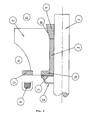
- FIG. 1 Elements of a cooling water pump with coupling arrangement are shown within a pump housing, not shown.
- the cooling water pump comprises a pump shaft 1, on which a pump wheel 2 is rotatably mounted via an axially and radially extending sliding bushing 3.
- the radial section 3a of the sliding bush 3 can abut against a radial bearing stop 4, for example in the form of a steel disc.
- a radial bearing stop for example in the form of a steel disc.
- the impeller 2 is as in FIG. 1 illustrated, preferably formed as an impeller, which is surrounded by a correspondingly shaped housing (not shown).
- a compression spring 5 with an engagement portion 6, which can cooperate positively and / or non-positively with the impeller 2.
- a V-shaped or wedge-shaped groove 2a is annularly introduced into the impeller 2, in which the engagement portion 6 retracts to produce a frictional engagement between the correspondingly adapted engagement portion 6 and the groove 2a.
- the engagement section 6 has form elements which fit into corresponding form elements in the V-shaped groove 2a, so that a positive connection is created in the engaged state.
- a magnetically conductive anchor member 7, for example, a ring member is mounted, which cooperates with an electromagnet 8.
- the solenoid 8 may be mounted inside or outside the pump housing. In an arrangement outside the pump housing, a magnetic passage must be ensured by the pump housing to the anchor member 7 in order to exert a magnetic force on the anchor member 7 when the solenoid 8 is energized.
- stop elements for example in the form of finger-shaped stop members are provided which axially restrict an axial movement of the anchor member 7 at a tightening force by the electromagnet 8.
- the electromagnet is subjected to a voltage which may be excessive in an initial period of time to pull the armature element against the electromagnet 8.
- a voltage which may be excessive in an initial period of time to pull the armature element against the electromagnet 8.
- the axial stop fingers, not shown, in the region of the compression spring 5 limit the axial travel of the anchor element 7, so that this can not come to rest on the electromagnet 8 when the electromagnet is energized.
- FIG. 2 an embodiment is shown in which the wedge-shaped groove 2a and the engagement portion 6 is replaced by a wedge member 9 which cooperates with a mating cone-shaped recess 10 on the impeller 2.
- the impeller 2 is displaced axially in the direction of the wedge member 9, whereby between the wedge member 9 and the conical recess 10 entstehz a frictional engagement.
- the impeller 2 preferably runs at the same speed as the pump shaft. 1
- the frictional torque between impeller 2 and wedge element 9 drives the impeller 2.
- the impeller 2 is pulled over an armature element 13 arranged in or on the impeller 2 in the direction of the electromagnet 8, thereby releasing the transmission of force between the wedge element 9 and the conical recess 10.
- the anchor element 13 may, for example, be cast into the impeller 2.
- the impeller is pressed against the bearing stop 11, for example in the form of a steel disc, which is designed so that no or substantially no drive torque is transmitted to the impeller when rotating the pump shaft 1. In this case, the impeller is disengaged. There is no pumping action.
- FIG. 3 an embodiment is shown, which is analogous to the embodiment of FIG. 2 operates, with the difference that the elements 8, 11, 12, 13 are transferred to the suction side, whereas the wedge member 9 and the matching cone-shaped recess 10 on the side facing away from the suction side 14 15 are arranged.
Landscapes
- Engineering & Computer Science (AREA)
- Mechanical Engineering (AREA)
- General Engineering & Computer Science (AREA)
- Chemical & Material Sciences (AREA)
- Combustion & Propulsion (AREA)
- Structures Of Non-Positive Displacement Pumps (AREA)
Abstract
Description
- Aus der europäischen Patentanmeldung
EP 2 105 624 ist eine elektromagnetisch betätigbare Kupplung für eine Wasserpumpe des Kühlwasserkreislaufs eines Verbrennungsmotors mit einem Antriebsrad bekannt, das im Bereich oder an der Wasserpumpe drehbar gelagert werden kann sowie mit einer Ankerscheibe, die mit einer Spule zusammen wirkt. Die Kupplung ist derart aufgebaut, dass eine so genannte "fail safe"-Anordnung geschaffen ist, bei welcher ein Antrieb-einer Wasserpumpe über die Kupplung auch im stromlosen Zustand der Spule möglich ist, wenn zum Beispiel ein Ausfall der elektrischen Spannungsversorgung stattfindet. - Der Erfindung liegt die Aufgabe zugrunde, eine Vorrichtung für eine Pumpe, insbesondere Wasserpumpe eines Kfz mit Kupplungsanordnung bereitzustellen, so dass eine schaltbare Pumpe mit kompaktem Aufbau entsteht.
- Diese Aufgabe wird durch die Merkmale des Anspruchs 1 oder 12 gelöst.
- In den abhängigen Ansprüchen sind vorteilhafte und zweckmäßige Weiterbildungen der Erfindung angegeben.
- Die Erfindung geht von einer Vorrichtung für eine Pumpe eines Kfz, insbesondere eine Wasserpumpe, zum Beispiel für den Kühlwasserkreislauf eines Verbrennungsmotors aus. Die Pumpe umfasst ein rotierendes anzutreibendes Pumpenrad und eine schaltbare Kupplungsanordnung zum schaltbaren Verbinden des Pumpenrads mit einer Antriebsseite. Der Kern der Erfindung liegt nun darin, dass das Pumpenrad auf einer rotierbaren Antriebswelle drehbar gelagert ist, so dass eine Relativbewegung zwischen Pumpenrad und Antriebswelle stattfinden kann. Damit kann sich das Pumpenrad auf Antriebswelle drehen. Durch diese Maßnahme wird es möglich, eine Kupplungsanordnung zumindest zum Teil in einfacher Weise in eine Pumpe, insbesondere innerhalb eines Pumpengehäuses zu integrieren. Die Lagerung des Pumpenrades auf der Antriebswelle kann über Wälzlager oder Gleitlager erfolgen. Vorzugsweise wird ein kostengünstiges Gleitlager eingesetzt, da die Betriebszeit, in welcher das Pumpenrad durch eine entsprechend geschaltete Kupplung eine deutlich kleinere Drehzahl aufweist als die Antriebswelle im Vergleich zur Gesamtnutzungszeit klein ist. Ein etwaig erhöht auftretender Verschleiß eines Gleitlagers im Vergleich zu einem Wälzlager ist daher beherrschbar.
- In einem eingekuppelten Zustand der Kupplung weist das Pumpenrad vorzugsweise die Drehzahl der Antriebswelle oder eine zumindest annähernde Drehzahl der Antriebswelle auf. Im Idealfall besteht jedoch kein Schlupf zwischen Antriebswelle und Pumpenrad. Im ausgekuppelten Zustand entsteht zumindest eine Relativdrehzahl zwischen dem Pumpenrad und einer nach wie vor sich drehenden Antriebswelle. Vorzugsweise befindet sich das Pumpenrad im Stillstand oder durch nach wie vor herrschende Reibkräfte in einem Zustand mit einer geringen Schleppdrehzahl.
- Zur Erzeugung eines ausgekuppelten und eingekuppelten Zustands des Pumpenrads wird im Weiteren vorgeschlagen, dass das Pumpenrad auf der Antriebswelle axial verschiebbar ist. Damit ist es denkbar, dass ein Reibabschnitt des Pumpenrads durch axiale Verschiebung mit Reibmitteln zusammen wirkt, die drehfest an der Antriebswelle angeordnet sind.
- Zur Erzeugung von Schaltzuständen der Kupplungsanordnung wird überdies vorgeschlagen, dass eine elektromagnetische Spule vorgesehen ist, die in einem bestromten Zustand auf ein magnetisch leitendes Ankerelement wirkt. Vorteilhafzersweise ist ein Ankerelement innerhalb eines Pumpengehäuses angeordnet. Die elektromagnetische Spule kann für einen kompakten und kostengünstigen Aufbau ebenfalls innerhalb des Pumpengehäuses angeordnet werden. Denkbar ist jedoch auch eine Anordnung außerhalb des Pumpergehäuses, was Vorteile im Hinblick auf eine elektrische Versorgung der Spule mit sich bringt.
- Im Weiteren ist es bevorzugt, wenn das Ankerelement durch eine elektromagnetische Einwirkung der Spule axial bewegbar ist, wobei durch eine sich einstellende axiale Position des Ankerelements der Schaltzustand des Pumpenrades vorgebbar ist. Hierdurch lässt sich zum Beispiel das Pumpenrad axial bewegen oder das Ankerelement bewegt ein weiteres Element, das auf das Pumpenrad zur Erzeugung eines Schaltzustand einwirkt.
- Zur übertragung eines Drehmoments der Antriebswelle auf das Pumpenrad wird in einer weiteren bevorzugten Ausgestaltung der Erfindung vorgeschlagen, dass drehfest an der Antriebswelle Kontaktmittel, insbesondere Reibmittel angeordnet sind, die für einen Kraft- und/oder Formschluss, insbesondere Kraftschluss mit einem Reibabschnitt an dem auf der Antriebswelle drehbaren Pumpenrad ausgelegt sind.
- In diesem Zusammenhang ist es außerdem bevorzugt, wenn das Ankerelement und die Reibmittel derart aufeinander abgestimmt sind, dass ein Reibschluss zwischen Antriebswelle und Pumpenrad in Abhängigkeit von einer axialen Position des Ankerelements entsteht.
- In einer besonders bevorzugten Ausgestaltung der Erfindung ist ein Verschiebeorgan vorgesehen, mittels dem ein Kontaktabschnitt, zum. Bespiel ein Reibabschnitt des Pumpenrades in Reibkontakt mit den Reibmitteln bringbar ist. Vorzugsweise wirkt das Verschiebeorgan, zum Beispiel eine Feder, insbesondere eine Druckfeder, in axiale Richtung auf das Pumpenrad bei einer nicht bestromten elektromagnetischen Spule, so dass ein Reibabschnitt des Pumpenrads gegen Reibmittel gedrängt wird, die drehfest mit der Antriebswelle verbunden sind. Auf diese Weise entsteht eine "fail safe"-Anordnung, die ein sich drehendes Pumpenrad auch dann gewährleistet, wenn an einem laufenden Verbrennungsmotor mit drehender Antriebswelle die Spannungsversorgung für die elektromagnetische Spule ausfällt. Insbesondere bei dem Einsatz der Pumpe in einem Kühlwasserkreislauf eines Verbrennungsmotors kann hierdurch eine hohe Betriebssicherheit gewährleistet werden.
- Außerdem vorteilhaft ist es, wenn das Ankerelement an einem Federelement angeordnet, das drehfest mit der Antriebswelle in Verbindung steht, wobei das Federelement dazu ausgelegt ist, auf das Pumpenrad eine axiale Druckwirkung auszuüben, Damit wird ebenfalls in einem nicht bestromten Zustand der elektromagnetischen Spule, bei welchem keine Kraftwirkung auf das Ankerelement auftritt, ein Reibschluss zwischen einem an dem Federelement angeordneten Reibmittel und einem entsprechenden Reibabschnitt am Pumpenrad ermöglicht, so dass eine "fail safe"-Anordnung entsteht. Durch Bestromen der Spule kann zum Beispiel das Ankerelement axial derart versetzt werden, dass Reibmittel, die federnd gegen das Pumpenrad drücken, von diesem abgehoben werden, so dass das Pumpehrad auf der Antriebswelle frei oder im Wesentlichen frei drehen kann.
- In einer außerdem bevorzugten Ausführungsform ist es vorteilhaft, wenn das Ankerelement am Pumpenrad angeordnet ist. Das Ankerelement kann auf der Ansaugseite oder auf der der Ansaugseite abgewandten Seite des Pumpenrades angebracht sein.
- Über ein Verschiebeorgan, insbesondere ein Federelement kann bei nicht bestromter elektrischer Spule das Pumpenrad in einen eingekuppelten Zustand gedrängt werden.
- Für eine definierte Positionierung des Pumpenrades ist es im Weiteren bevorzugt, wenn an der Antriebswelle für das Pumpenrad ein axialer Lageranschlag ausgebildet ist. Der Lageranschlag hat vorzugsweise die Funktionalität eines Drehlagers, so dass in einem Fall, in welchem das Pumpenrad mit axialer Druckkraft am Lageranschlag ansteht, und darüber hinaus zum Beispiel keine weiteren Reibkräfte von Reibmitteln erfährt, auch dann im Wesentlichen frei drehen kann.
- In einer bevorzugten Ausführungsform umfassen die Reibmittel auf der Antriebswelle ein Keilelement, das mit einem Reibabschnitt des Pumpenrads in Reibschluss bringbar ist. Auf diese Weise kann mit vergleichsweise geringer axialer Verschiebekraft durch einen "Keilgetriebeeffekt" einer keilförmigen Reibfläche über Reibschluss das Pumpenrad auf die Drehzahl der Antriebswelle gebracht werden.
- Die erfindungsgemäße Vorrichtung wird vorzugsweise für Pumpen in einem Kfz, insbesondere Wasserpumpen eingesetzt. Bei Verbrennungsmotoren ist der bevorzugte Anwendungsfall die Wasserpumpe für den Kühlwasserkreislauf. Durch eine schaltbare Kühlwasserpumpe lässt sich der Motor schneller auf Betriebstemperatur bringen, wenn er aus dem kalten Zustand hochfährt. Dazu wird in dieser Phase des Motorbetriebs der Kühlwasserkreislauf durch Auskuppeln des Pumpenrads abgeschaltet. Sobald der Motor dann auf vorgegebener Betriebstemperatur ist, wird das Pumpenrad eingekoppelt, womit der Kühlwasserkreislauf in Gang kommt.
- Mehrere Ausführungsbeispiele der Erfindung sind in den Figuren dargestellt und werden unter Angabe weiterer Vorteile und Einzelheiten nachfolgend näher erläutert.
- Es zeigt:
- Figur 1
- in schematischer Darstellung eine teilweise geschnittene Seitenansicht von Teilen einer Kühlwasserpumpe mit Kupplungsanordnung und
- Figur 2 und 3
- in einer entsprechenden Darstellung zwei weitere Ausführungsformen für vergleichbare Teile.
- In
Figur 1 sind Elemente einer Kühlwasserpumpe mit Kupplunganordnung innerhalb eines nicht dargestellten Pumpengehäuses abgebildet. Die Kühlwasserpumpe umfasst eine Pumpenwelle 1, auf der ein Pumpenrad 2 über eine sich axial und radial erstreckende Gleitbuchse 3 drehbar gelagert ist. Der radiale Abschnitt 3a der Gleitbuchse 3 kann an einem radialen Lageranschlag 4 zum Beispiel in Form einer Stahlscheibe anliegen. In den Lageranschlag kann vorzugsweise auch eine Gleitringdichtung oder eine ähnliche Dichtung integriert sein. Das Pumpenrad 2 ist wie inFigur 1 dargestellt, vorzugsweise als Impeller ausgebildet, der von einem entsprechend geformten Gehäuse (nicht dargestellt) umgeben ist. - An der Antriebswelle drehfest montiert ist eine Druckfeder 5 mit einem Eingriffsabschnitt 6, der form- und/oder kraftschlüssig mit dem Pumpenrad 2 zusammenwirken kann. Vorliegend ist in das Pumpenrad 2 eine V-förmige bzw. keilförmige Nut 2a kreisringförmig eingebracht, in welcher der Eingriffabschnitt 6 einfährt, um zwischen dem entsprechend angepassten Eingriffsabschnitt 6 und der Nut 2a einen Reibschluss zu erzeugen.
- Denkbar ist jedoch auch, dass der Eingriffsabschnitt 6 Formelemente aufweist, die zu entsprechenden Formelementen in der V-förmigen Nut 2a passen, so dass im eingekuppelten Zustand ein Formschluss entsteht.
- Am Eingriffsabschnitt 6 ist ein magnetisch leitendes Ankerelement 7, zum Beispiel ein Ringelement angebracht, das mit einem Elektromagnet 8 zusammenwirkt. Der Elektromagnet 8 kann innerhalb oder außerhalb des Pumpengehäuses angebracht sein. Bei einer Anordnung außerhalb des Pumpengehäuses muss ein magnetischer Durchlass durch das Pumpengehäuse zum Ankerelement 7 gewährleistet sein, um eine magnetische Kraftwirkung auf das Ankerelement 7 ausüben zu können, wenn der Elektromagnet 8 bestromt ist.
- Zur Bewegungsbegrenzung der Druckfeder 5, an welcher der Eingriffsabschnitt 6 und das Ankerelement 7 angeordnet sind, werden vorzugsweise Anschlagelemente, zum Beispiel in Form von fingerförmigen Anschlagelementen vorgesehen, die eine axiale Bewegung des Ankerelements 7 bei einer Anzugskraft durch den Elektromagneten 8 axial beschränken.
- Die Funktion einer Wasserpumpenanordnung gemäß
Figur 1 stellt sich wie folgt dar: - Aufgrund dessen, dass im nicht bestromten Zustand des Elektromagneten 8 der Eingriffsabschnitt gegen das Pumpenrad 2 drückt, entsteht eine "fail safe"-Anordnung, bei welcher im stromlosen Zustand über die Reibwirkung des Eingriffsabschnitts 6 das Pumpenrad auf der gleichen Drehzahl läuft, wie die Pumpenwelle 1.
- Um das Pumpenrad "auszukoppeln", wird der Elektromagnet mit einer Spannung beaufschlagt, die in einer Anfangszeitspanne überhöht sein kann, um das Ankerelement gegen den Elektromagneten 8 zu ziehen. Damit löst sich der Reibschluss zwischen dem Eingriffsabschnitt 6 und der keilförmigen Nut 2 und das Pumpenrad ist danach frei drehbar auf der Pumpenwelle 1 gelagert. Die nicht dargestellten axialen Anschlagfinger im Bereich der Druckfeder 5 begrenzen den axialen Weg des Ankerelements 7, so dass dieses bei bestromtem Elektromagnet nicht zu Anlage am Elektromagnet 8 kommen kann.
- In
Figure 2 ist eine Ausführungsform dargestellt, bei welcher die keilförmige Nut 2a und der Eingriffsabschnitt 6 durch ein Keilelement 9 ersetzt ist, das mit einer dazu passenden konusförmigen Ausnehmung 10 am Pumpenrad 2 zusammenwirkt. Ein Lageranschlag 11, der dem radialen Abschnitt 3a der Lagerbuchse 3 gegenüber liegt, ist axial bewegbar und wird durch eine Druckfeder in axialer Richtung gegen das Pumpenrad 2 gedrückt. Damit wird das Pumpenrad 2 axial in Richtung des Keilelements 9 verschoben, womit zwischen dem Keilelement 9 und der konusförmigen Ausnehmung 10 ein Reibschluss entstehz. In diesem Zustand läuft das Pumpenrad 2 vorzugsweise auf der gleichen Drehzahl wie die Pumpenwelle 1. - Das Reibmoment zwischen Pumpenrad 2 und Keilelement 9 treibt das Pumpenrad 2 an. Durch Bestromung des Elektromagneten 8 wird das Pumpenrad 2 über ein im oder am Pumpenrad 2 angeordnetes Ankerelement 13 in Richtung des Elektromagneten 8 gezogen und dadurch die Kraftübertragung zwischen dem Keilelement 9 und der konusförmigen Ausnehmung 10 gelöst. Das Ankerelement 13 kann zum Beispiel in das Pumpenrad 2 eingegossen sein. Das Pumpenrad wird gegen den Lageranschlag 11, zum Beispiel in Form einer Stahlscheibe gepresst, wobei dieser so ausgebildet ist, dass kein oder im Wesentlichen kein Antriebsmoment auf das Pumpenrad bei sich drehender Pumpenwelle 1 übertragen wird. In diesem Fall ist das Pumpenrad ausgekuppelt. Es findet keine Pumpwirkung statt.
- In
Figur 3 ist eine Ausführungsform dargestellt, die analog zu der Ausführungsform nachFigur 2 arbeitet, mit dem Unterschied dass die Elemente 8, 11, 12, 13 auf die Saugseite transferiert sind, wogegen das Keilelement 9 und die dazu passende konusförmige Ausnehmung 10 auf ,der der Ansaugseite 14 abgewandten Seite 15 angeordnet sind. - Entsprechend wie im Ausführungsbeispiel nach
Figur 2 wird im stromlosen Zustand des Elektromagneten 8 durch die Druckfeder 12 das Pumpenrad 2 gegen das Keilelement 9 gedrückt, womit das Antriebsmoment der Pumpenwelle 1 auf das Pumpenrad 2 durch Reibschluss übertragbar ist. Durch Bestromung des Elektromagneten 8 kann das Pumpenrad 2 ausgekuppelt werden, in dem über das Ankerelement 13 das Pumpenrad 2 vom Keilelement 9 weggezogen wird, mittels einer Axialbewegung des Pumpenrads 2 auf der Pumpenwelle 1. Dies stellt den ausgekuppelten Zustand dar. -
- 1
- Pumpenwelle
- 2
- Pumpenrad
- 2a
- Nut
- 3
- Lagerbuchse
- 3a
- radialer Abschnitt
- 4
- Lageranschlag
- 5
- Druckfeder
- 6
- Engriffsabschnitt
- 7
- Ankerelement
- 8
- Elektromagnet
- 9
- Keilelement
- 10
- konusförmige Ausnehmung
- 11
- Lageranschlag
- 12
- Druckfeder
- 13
- Ankerelement
- 14
- Ansaugseite
- 15
- abgewandte Seite
Claims (12)
- Vorrichtung für eine Pumpe eines Kraftfahrzeugs, insbesondere Wasserpumpe mit einem rotierenden anzutreibenden Pumpenrad (2) und einer schaltbaren Kupplungsanordnung zum schaltbaren Verbinden des Pumpenrads (2) mit einer Antriebsseite, dadurch gekennzeichnet, dass das Pumpenrad (2) auf einer rotierbaren Antriebswelle (1) drehbar gelagert ist.
- Vorrichtung nach Anspruch 1, dadurch gekennzeichnet, dass das Pumpenrad (2) auf der Antriebswelle (1) axial verschiebbar angeordnet ist.
- Vorrichtung nach einem der vorhergehenden Ansprüche, dadurch gekennzeichnet, dass eine elektromagnetische Spule (8) vorgesehen ist, die in einem bestromten Zustand auf ein magnetisch leitendes Ankerelement (7, 13) wirkt.
- Vorrichtung nach einem der vorhergehenden Ansprüche, dadurch gekennzeichnet, dass das Ankerelement (7, 13) durch eine magnetische Einwirkung der Spule (8) axial bewegbar ist, wobei durch eine sich einstellende axiale Position des Ankerelements (7, 13) der Schaltzustand des Pumpenrades (2) vorgebbar ist.
- Vorrichtung nach einem der vorhergehenden Ansprüche, dadurch gekennzeichnet, dass drehfest an der Antriebswelle (1) Kcntaktmittel (6, 9) angeordnet sind, die für einen Kraft-und/oder Formschluss mit einem Kontaktabschnitt (2a, 10) an dem auf der Antriebswelle drehbaren Pumpenrad ausgelegt sind.
- Vorrichtung nach einem der vorhergehenden Ansprüche, dadurch gekennzeichnet, dass das Ankerelement (7, 13) und die Kontaktmittel (6, 9) derart aufeinander abgestimmt sind, dass ein Kraft- und/oder Formschluss zwischen Antriebswelle und Pumpenrad in Abhängigkeit von einer axialen Position des Ankerelements (7, 13) vorgebbar ist.
- Vorrichtung nach einem der vorhergehenden Ansprüche, dadurch gekennzeichnet, dass ein Verschiebeorgan (12) vorgesehen ist, mittels dessen ein Kontaktabschnitt (10) am Pumpenrad in Form- und/oder Reibschluss mit den Kontaktmitteln (9) bringbar ist.
- Vorrichtung nach einem der vorhergehenden Ansprüche, dadurch gekennzeichnet, dass das Ankerelement (7) an einem Federelement (5) angeordnet ist, das drehfest mit der Antriebswelle (1) in Verbindung steht, wobei das Federelement (5) dazu ausgelegt ist, auf das Pumpenrad axial zu drücken.
- Vorrichtung nach einem der vorhergehenden Ansprüche, dadurch gekennzeichnet, dass das Ankerelement (13) am Pumpenrad angeordnet ist.
- Vorrichtung nach einem der vorhergehenden Ansprüche, dadurch gekennzeichnet, dass an der Antriebswelle (1) für das Pumpenrad ein axial wirkender Lageranschlag (4, 11) ausgebildet ist.
- Vorrichtung nach einem der vorhergehenden Ansprüche, dadurch gekennzeichnet, dass die Kontaktmittel auf der Antriebswelle (1) ein Reibmittel in Form eines Keilelements (9) umfassen, das mit einem Reibabschnitt (10) des Pumpenrades (2) in Reibschluss bringbar ist.
- Pumpe für ein Kfz, insbesondere Wasserpumpe mit einer Vorrichtung nach einem der vorhergehenden Ansprüche.
Applications Claiming Priority (1)
| Application Number | Priority Date | Filing Date | Title |
|---|---|---|---|
| DE102010005936A DE102010005936A1 (de) | 2010-01-26 | 2010-01-26 | Vorrichtung für eine Pumpe sowie Wasserpumpe |
Publications (2)
| Publication Number | Publication Date |
|---|---|
| EP2354552A2 true EP2354552A2 (de) | 2011-08-10 |
| EP2354552A3 EP2354552A3 (de) | 2016-01-27 |
Family
ID=43778465
Family Applications (1)
| Application Number | Title | Priority Date | Filing Date |
|---|---|---|---|
| EP11000402.5A Withdrawn EP2354552A3 (de) | 2010-01-26 | 2011-01-20 | Vorrichtung für eine Pumpe sowie Wasserpumpe |
Country Status (3)
| Country | Link |
|---|---|
| US (1) | US20110182757A1 (de) |
| EP (1) | EP2354552A3 (de) |
| DE (1) | DE102010005936A1 (de) |
Cited By (1)
| Publication number | Priority date | Publication date | Assignee | Title |
|---|---|---|---|---|
| WO2016179619A1 (de) * | 2015-05-13 | 2016-11-17 | Bitter Engineering & Systemtechnik Gmbh | Kreiselpumpe mit verschiebbarem rotor |
Citations (1)
| Publication number | Priority date | Publication date | Assignee | Title |
|---|---|---|---|---|
| EP2105624A1 (de) | 2008-03-28 | 2009-09-30 | Linnig Trucktec GmbH | Elektromagnetisch betätigbare Kupplung sowie Wasserpumpe mit einer elektromagnetisch betätigbaren Kupplung |
Family Cites Families (39)
| Publication number | Priority date | Publication date | Assignee | Title |
|---|---|---|---|---|
| US1455910A (en) * | 1921-02-12 | 1923-05-22 | Jr George V Domarus | Adjustable motor fan |
| US1665742A (en) * | 1927-04-28 | 1928-04-10 | Sunlight Electrical Mfg Compan | Induction motor |
| US2413295A (en) * | 1944-04-27 | 1946-12-31 | Miner Inc W H | Friction shock absorber |
| US2569144A (en) * | 1946-11-21 | 1951-09-25 | T M K Corp | Overload release friction coupling |
| US2770316A (en) * | 1954-10-21 | 1956-11-13 | Allis Louis Co | Apparatus for collecting air contaminants |
| US3404631A (en) * | 1966-06-09 | 1968-10-08 | Westinghouse Electric Corp | Centrifugal pump |
| US3407740A (en) * | 1967-04-14 | 1968-10-29 | Borg Warner | Variable geometry centrifugal pump |
| US4020864A (en) * | 1975-07-16 | 1977-05-03 | Church Jr Edgar H | Ball valve |
| US4089620A (en) * | 1976-10-26 | 1978-05-16 | Riga, Inc. | Floating pumping device |
| YU39673B (en) * | 1977-02-21 | 1985-03-20 | Titovi Zavodi Litostroj | Single-stage reversible pump turbine with a supplemental pump |
| US4271781A (en) * | 1978-10-25 | 1981-06-09 | Cowie David B | Outboard motor clutches |
| DE3329002C2 (de) * | 1983-08-11 | 1985-08-22 | Daimler-Benz Ag, 7000 Stuttgart | Kühlmittelpumpe an einer Brennkraftmaschine für insbesondere Fahrzeuge |
| JPS6069334U (ja) * | 1983-10-19 | 1985-05-16 | 三菱電機株式会社 | 内燃機関用補助動力出力装置 |
| DE3611708A1 (de) * | 1986-04-08 | 1987-10-22 | Audi Ag | Kuehlmittelpumpe fuer eine fahrzeug-brennkraftmaschine |
| US4836147A (en) * | 1987-12-14 | 1989-06-06 | Ford Motor Company | Cooling system for an internal combustion engine |
| DE3927391A1 (de) * | 1989-08-19 | 1991-02-21 | Bosch Gmbh Robert | Vorrichtung zum beheizen des fahrgastraumes eines kraftfahrzeuges |
| US5209650A (en) * | 1991-02-28 | 1993-05-11 | Lemieux Guy B | Integral motor and pump |
| US5154493A (en) * | 1991-05-01 | 1992-10-13 | Futrell Michael O | Anti-theft brake lock |
| US5494413A (en) * | 1993-12-09 | 1996-02-27 | Westinghouse Electric Corporation | High speed fluid pump powered by an integral canned electrical motor |
| CA2189379C (en) * | 1995-11-07 | 2002-01-01 | Thomas W. Ramsay | Pump impeller with adjustable blades |
| DE19752372A1 (de) * | 1997-11-26 | 1999-05-27 | Guenther Dipl Ing Beez | Regelbare Kreiselpumpe, insbesondere für Verbrennungsmotore |
| CA2369956C (en) * | 1999-04-20 | 2007-09-25 | Johan K. Fremerey | Rotor device |
| US6061225A (en) * | 1999-05-03 | 2000-05-09 | Nordson Corporation | Method and apparatus for controlling a solenoid within an electric dispensing gun |
| DE10012181C2 (de) * | 2000-03-13 | 2002-05-16 | Ritz Pumpenfabrik Gmbh & Co Kg | Kreiselpumpe mit Noppen-Laufrad und Noppen-Laufrad hierfür |
| DE10050161A1 (de) * | 2000-10-11 | 2002-04-18 | Daimler Chrysler Ag | Abgasturbolader für eine Brennkraftmaschine und Verfahren zum Betrieb eines Abgasturboladers |
| FR2827920B1 (fr) * | 2001-07-27 | 2004-03-12 | Peugeot Citroen Automobiles Sa | Pompe hydraulique et circuit de refroidissement comportant une telle pompe |
| DE10142263C1 (de) * | 2001-08-29 | 2002-10-24 | Guenther Beez | Regelbare Kühlmittelpumpe |
| DE10158732B4 (de) * | 2001-11-30 | 2008-11-27 | Linnig Trucktec Gmbh | Antriebsorgan für eine Wasserpumpe des Kühlwasserkreislaufes eines Verbrennungsmotors sowie Reibschaltkupplung |
| GB2404220A (en) * | 2003-07-23 | 2005-01-26 | Visteon Global Tech Inc | variable speed mechanically-driven vehicular water pump with supplementary electrical drive |
| DE102005056199A1 (de) * | 2005-11-25 | 2006-10-12 | Audi Ag | Pumpe für ein flüssiges Medium, insbesondere Kühlmittelpumpe, sowie Stellelement für eine solche Pumpe |
| JP4886355B2 (ja) * | 2006-05-02 | 2012-02-29 | 日本トムソン株式会社 | 可動マグネット型リニアモータを内蔵したスライド装置 |
| DE102006039680A1 (de) * | 2006-08-24 | 2008-02-28 | Audi Ag | Kühlmittelpumpe für einen Kühlkreislauf einer Verbrennungskraftmaschine |
| DE102006048482A1 (de) * | 2006-10-11 | 2008-04-17 | Behr Gmbh & Co. Kg | Koppelungsvorrichtung für eine Kühlmittelpumpe, Verfahren zum Koppeln, Pumpe zum Kühlmittelpumpen |
| AT505644B1 (de) * | 2007-09-06 | 2011-09-15 | Tcg Unitech Systemtechnik Gmbh | Kühlmittelpumpe |
| US7597070B2 (en) * | 2008-02-06 | 2009-10-06 | Ford Global Technologies, Llc | Dual drive radiator fan and coolant pump system for an internal combustion engine |
| US8808124B2 (en) * | 2008-04-15 | 2014-08-19 | GM Global Technology Operations LLC | Belt alternator starter systems for hybrid vehicles |
| CN201966719U (zh) * | 2011-03-31 | 2011-09-07 | 费吉祥 | 带有密封圈的电机端盖 |
| JP5734765B2 (ja) * | 2011-06-24 | 2015-06-17 | トヨタ自動車株式会社 | 回転電機の冷却構造 |
| US20130241326A1 (en) * | 2012-03-19 | 2013-09-19 | Hamilton Sundstrand Corporation | Liquid cooled dynamoelectric machine |
-
2010
- 2010-01-26 DE DE102010005936A patent/DE102010005936A1/de not_active Withdrawn
-
2011
- 2011-01-20 EP EP11000402.5A patent/EP2354552A3/de not_active Withdrawn
- 2011-01-21 US US13/010,946 patent/US20110182757A1/en not_active Abandoned
Patent Citations (1)
| Publication number | Priority date | Publication date | Assignee | Title |
|---|---|---|---|---|
| EP2105624A1 (de) | 2008-03-28 | 2009-09-30 | Linnig Trucktec GmbH | Elektromagnetisch betätigbare Kupplung sowie Wasserpumpe mit einer elektromagnetisch betätigbaren Kupplung |
Cited By (1)
| Publication number | Priority date | Publication date | Assignee | Title |
|---|---|---|---|---|
| WO2016179619A1 (de) * | 2015-05-13 | 2016-11-17 | Bitter Engineering & Systemtechnik Gmbh | Kreiselpumpe mit verschiebbarem rotor |
Also Published As
| Publication number | Publication date |
|---|---|
| US20110182757A1 (en) | 2011-07-28 |
| EP2354552A3 (de) | 2016-01-27 |
| DE102010005936A1 (de) | 2011-07-28 |
Similar Documents
| Publication | Publication Date | Title |
|---|---|---|
| EP2105624B1 (de) | Elektromagnetisch betätigbare Kupplung sowie Wasserpumpe mit einer elektromagnetisch betätigbaren Kupplung | |
| DE10158732B4 (de) | Antriebsorgan für eine Wasserpumpe des Kühlwasserkreislaufes eines Verbrennungsmotors sowie Reibschaltkupplung | |
| DE2804859C3 (de) | Flüssigkeitsreibungskupplung, insbesondere für ein Kühlgebläse einer Brennkraftmaschine | |
| DE102008042776B3 (de) | Adaptive Kühleinrichtung für ein Elektrowerkzeug | |
| DE102011010284B4 (de) | Riementriebanordnung für ein Nebenaggregat eines Kraftfahrzeugs und Kraftfahrzeug mit einer solchen Riementriebanordnung | |
| DE102012102058B4 (de) | Kombinierte Reibscheiben- und Flüssigkeitsreibungskupplung | |
| EP2284414B1 (de) | Flüssigkeitsreibungskupplung | |
| EP1566526A2 (de) | Regelbarer Antrieb für ein Kraftfahrzeug | |
| EP1509684B1 (de) | Vorrichtung zur relativen winkelverstellung zwischen zwei rotierenden elementen | |
| DE102010017645A1 (de) | Elektromagnetisches Relais für Anlasser | |
| DE102009056368A1 (de) | Schaltbare Antriebsscheibe mit einer elektrisch betätigten, eine Reibscheibe aufweisenden Drehmomentübertragungsvorrichtung | |
| DE102016206675A1 (de) | Kupplungssystem | |
| DE19746359A1 (de) | Pumpe, insbesondere regelbare Kühlmittelpumpe, für Kraftfahrzeuge | |
| EP2390493B1 (de) | Startermotor in einem Starter für eine Brennkraftmaschine | |
| DE102017130739A1 (de) | Hilfsantriebssystem für eine Pumpe | |
| DE102009015151A1 (de) | Reibungskupplung mit Betätigungseinrichtung | |
| DE102009026626A1 (de) | Kupplung oder Bremse in oder an einem Getriebe | |
| DE102014223327A1 (de) | Nebenaggregatantrieb mit Reibungskupplung und Elektromotor | |
| EP2354552A2 (de) | Vorrichtung für eine Pumpe sowie Wasserpumpe | |
| EP2221496B1 (de) | Trennvorrichtung für eine reibungskupplung | |
| DE102011050359A1 (de) | Kupplungsanordnung | |
| EP2017490B1 (de) | Wasserpumpen-Trennkupplung | |
| DE102005022457A1 (de) | Elektromagnetisch schaltbare Kupplung | |
| EP3760892B1 (de) | Lamellenbremse für einen fahrzeugantrieb und ein fahrzeugantrieb | |
| DE112017008238B4 (de) | Schaltbare mechanische Kühlmittelpumpe |
Legal Events
| Date | Code | Title | Description |
|---|---|---|---|
| PUAI | Public reference made under article 153(3) epc to a published international application that has entered the european phase |
Free format text: ORIGINAL CODE: 0009012 |
|
| AK | Designated contracting states |
Kind code of ref document: A2 Designated state(s): AL AT BE BG CH CY CZ DE DK EE ES FI FR GB GR HR HU IE IS IT LI LT LU LV MC MK MT NL NO PL PT RO RS SE SI SK SM TR |
|
| AX | Request for extension of the european patent |
Extension state: BA ME |
|
| 17P | Request for examination filed |
Effective date: 20130109 |
|
| PUAL | Search report despatched |
Free format text: ORIGINAL CODE: 0009013 |
|
| AK | Designated contracting states |
Kind code of ref document: A3 Designated state(s): AL AT BE BG CH CY CZ DE DK EE ES FI FR GB GR HR HU IE IS IT LI LT LU LV MC MK MT NL NO PL PT RO RS SE SI SK SM TR |
|
| AX | Request for extension of the european patent |
Extension state: BA ME |
|
| RIC1 | Information provided on ipc code assigned before grant |
Ipc: F04D 29/20 20060101ALI20151223BHEP Ipc: F04D 13/02 20060101AFI20151223BHEP Ipc: F01P 7/16 20060101ALI20151223BHEP Ipc: F04D 15/00 20060101ALI20151223BHEP Ipc: F01P 5/12 20060101ALI20151223BHEP Ipc: H02K 49/10 20060101ALI20151223BHEP |
|
| STAA | Information on the status of an ep patent application or granted ep patent |
Free format text: STATUS: THE APPLICATION IS DEEMED TO BE WITHDRAWN |
|
| 18D | Application deemed to be withdrawn |
Effective date: 20160802 |