EP2354662A2 - Burner assembly for a gas turbine plant and a gas turbine plant comprising said burner assembly - Google Patents
Burner assembly for a gas turbine plant and a gas turbine plant comprising said burner assembly Download PDFInfo
- Publication number
- EP2354662A2 EP2354662A2 EP10197322A EP10197322A EP2354662A2 EP 2354662 A2 EP2354662 A2 EP 2354662A2 EP 10197322 A EP10197322 A EP 10197322A EP 10197322 A EP10197322 A EP 10197322A EP 2354662 A2 EP2354662 A2 EP 2354662A2
- Authority
- EP
- European Patent Office
- Prior art keywords
- burner assembly
- burner
- combustion zone
- auxiliary
- air
- Prior art date
- Legal status (The legal status is an assumption and is not a legal conclusion. Google has not performed a legal analysis and makes no representation as to the accuracy of the status listed.)
- Granted
Links
Images




Classifications
-
- F—MECHANICAL ENGINEERING; LIGHTING; HEATING; WEAPONS; BLASTING
- F23—COMBUSTION APPARATUS; COMBUSTION PROCESSES
- F23R—GENERATING COMBUSTION PRODUCTS OF HIGH PRESSURE OR HIGH VELOCITY, e.g. GAS-TURBINE COMBUSTION CHAMBERS
- F23R3/00—Continuous combustion chambers using liquid or gaseous fuel
- F23R3/28—Continuous combustion chambers using liquid or gaseous fuel characterised by the fuel supply
- F23R3/34—Feeding into different combustion zones
- F23R3/343—Pilot flames, i.e. fuel nozzles or injectors using only a very small proportion of the total fuel to insure continuous combustion
-
- F—MECHANICAL ENGINEERING; LIGHTING; HEATING; WEAPONS; BLASTING
- F23—COMBUSTION APPARATUS; COMBUSTION PROCESSES
- F23C—METHODS OR APPARATUS FOR COMBUSTION USING FLUID FUEL OR SOLID FUEL SUSPENDED IN A CARRIER GAS OR AIR
- F23C2900/00—Special features of, or arrangements for combustion apparatus using fluid fuels or solid fuels suspended in air; Combustion processes therefor
- F23C2900/99001—Cold flame combustion or flameless oxidation processes
-
- Y—GENERAL TAGGING OF NEW TECHNOLOGICAL DEVELOPMENTS; GENERAL TAGGING OF CROSS-SECTIONAL TECHNOLOGIES SPANNING OVER SEVERAL SECTIONS OF THE IPC; TECHNICAL SUBJECTS COVERED BY FORMER USPC CROSS-REFERENCE ART COLLECTIONS [XRACs] AND DIGESTS
- Y02—TECHNOLOGIES OR APPLICATIONS FOR MITIGATION OR ADAPTATION AGAINST CLIMATE CHANGE
- Y02E—REDUCTION OF GREENHOUSE GAS [GHG] EMISSIONS, RELATED TO ENERGY GENERATION, TRANSMISSION OR DISTRIBUTION
- Y02E20/00—Combustion technologies with mitigation potential
- Y02E20/34—Indirect CO2mitigation, i.e. by acting on non CO2directly related matters of the process, e.g. pre-heating or heat recovery
Definitions
- the present invention relates to a burner assembly for a gas turbine plant and to a gas turbine plant comprising said burner assembly.
- Such a technology substantially includes an annular combustion chamber comprising a plurality of equally spaced burner assemblies, each of which comprises a premix burner and a pilot burner.
- the premix burner is supplied with an air-fuel mixture, with high excess of air, in order to cause a flame such as to ensure a uniform temperature range and avoid possible temperature peaks which could lead to high NOx emissions at the exhaust.
- the pilot burner is supplied with fuel and air, and stabilizes the flame produced by the premix burner.
- thermo-acoustic instability phenomena commonly known as “humming” which are determined by the fluctuation of the parameters of the fluid within the combustion chamber. These thermo-acoustic instability phenomena are dangerous for the structure of the combustion chamber itself.
- pilot burner is not supplied with air in excess and is therefore responsible for most NOx emissions of the burner assembly.
- the present invention relates to a burner assembly in accordance with claim 1.
- the present invention relates to a gas turbine plant for the production of energy in accordance with claim 11.
- numeral 1 indicates a plant for the production of electric power comprising a gas turbine 2, which extends along an axis A, a compressor 3, a combustion chamber 4, an assembly 6 for supplying fuel to the combustion chamber 4 and a generator 7, which transforms mechanical power provided by the gas turbine 2 into output electric power.
- the combustion chamber 4 is of the annular type and comprises a plurality of seats 8, each of which is adapted to be engaged by a burner assembly 9 (shown in greater detail in figures 2-6 ).
- Seats 8 are arranged along a circular path close to a peripheral edge of combustion chamber 4. There are twenty-four seats 8 and burner assemblies 9 in the non-limitative example shown herein.
- each burner assembly 9 extends along an axis B and comprises a main burner 10 and an auxiliary burner 11.
- the auxiliary burner 11 substantially extends along axis B, while the main burner 10 extends about the auxiliary burner 11 parallel to axis B.
- Main burner 10 is configured to supply an air-fuel mixture and to define a main combustion zone 12 (diagrammatically indicated by a dashed line in the figure).
- Air and fuel are supplied along a supplying direction D1 directed towards the inside of combustion chamber 4.
- main burner 10 comprises an annular air supply pipe 13 and an annular fuel supply pipe 14.
- the annular air supply pipe 13 receives air from compressor 3 and has a radial height decreasing in the supplying direction D1 so as to define a pipe having a substantially frustoconical shape.
- the annular fuel supply pipe 14 extends parallel to axis B and ends with a plurality of nozzles 15, which directly face the annular air supply pipe 13.
- the nozzles 15 are organized in groups of nozzles aligned and inclined with respect to axis B.
- the groups of nozzles 15 preferably comprise four or five nozzles.
- the annular air supply pipe 13 is provided with a cylindrical outlet element 17, commonly named cylindrical Burner Outlet", which extends parallel to axis B.
- the main combustion zone 12 in which the combustion of the air-fuel mixture from the annular air supply pipe 13 occurs, extends close to the end portion 16 of the annular air supply pipe 13 and to the cylindrical outlet element 12.
- Auxiliary burner 11 is designed to cause a combustion process in an auxiliary combustion zone 19 and to supply the main combustion zone 12 with fumes produced by the combustion process in the auxiliary combustion zone 19.
- auxiliary burner 11 is designed to cause a combustion process of the flameless type in the auxiliary combustion zone 19.
- Flameless combustion process means a combustion process obtained by preheating the combustion air and recirculating burnt gases.
- the air preheating conditions are obtained by recirculating the fumes. Thereby, indeed, the heat is transferred from the products to the reactants and the comburent is diluted with fuel and combustion products.
- a homogeneous combustion reaction may be developed within an auxiliary combustion zone, not being concentrated on a flame front. This determines a homogenous temperature in the auxiliary combustion zone, which in turn results in a reduction of the temperature peaks responsible for the formation of nitrogen oxides (NOx) of thermal origin.
- NOx nitrogen oxides
- auxiliary burner adapted to cause a flameless combustion process in an auxiliary combustion zone and to supply the main combustion zone 12 with the fumes produced by the combustion process in the auxiliary combustion zone.
- burner assembly 9 comprises an auxiliary burner 11 provided with a primary channel 20 for supplying air, a secondary channel 21 for supplying air, a fuel supplying channel 22 and a flow guiding device 23.
- the primary channel 20 and the secondary channel 21 are supplied with air from compressor 3.
- the fuel supplying channel 22 is preferably supplied with gas.
- the secondary channel 21 substantially extends along axis B
- the fuel supplying channel 22 extends about the secondary channel 21 parallel to axis B
- the primary channel 20 extends about the fuel supplying channel 22 parallel to axis B.
- the flow guiding device 23 is arranged along the primary channel 20 substantially at the auxiliary combustion zone 19 and is designed to produce at least one localized recirculation of combustion fumes in the auxiliary combustion zone 19.
- the flow guiding device 23 comprises a first partition 26, a second partition 27 and a third partition 28, which are arranged along the primary pipe 20 and projects from the outer wall 29 of the fuel supplying channel 22 in a direction substantially perpendicular to axis B.
- First partition 26, second partition 27 and third partition 28 are arranged in sequence at a given distance from one another along the supplying direction D1, so as to define, along with the outer wall 29 of the fuel supplying channel 22, a first recirculation area 30 (as shown by the arrows in figure 2 ) of the auxiliary combustion zone 19 between the first partition 26 and the second partition 27, and a second recirculation area 31 (as shown by the arrows in figure 2 ) in the auxiliary combustion zone 19 between second partition 27 and third partition 28.
- the first recirculation area 30 and the second recirculation area 31 are open and communicate with the primary channel 20.
- First partition 26, second partition 27 and third partition 28 are hollow and fluidically connected to the fuel supplying channel 22.
- the third partition 28 is also fluidically connected to the secondary channel 21 and has a substantially circular bottom face 33, which is provided with outlet holes 34 for the air from the secondary channel 21.
- Second partition 27 and third partition 28 are provided with respective fuel inlet ports 35 and 36, which face the first recirculation area 30 and the second recirculation area 31 of the auxiliary combustion zone 19, respectively.
- the outer wall 29 of the fuel supplying channel 22 is provided with at least two air inlet ports 37 communicating with the secondary channel 21 and adapted to supply air to the first recirculation area 30 and to the second recirculation area 31, respectively.
- the flow guiding device 23 is preferably provided with a baffle 38 arranged upstream of the first partition 26 along the supplying direction D1.
- the flow guiding device 23 is shaped so as to convey the air flow flowing along the primary channel 20 towards the first recirculation area 30 and the second recirculation area 31.
- the air from the primary channel 20, the air from the secondary channel 21 and the fuel from the fuel supplying channel 22 flow into the first recirculation area 30 and into the second recirculation area 31.
- FIG 3 shows a second embodiment of a burner assembly 39 in which the same reference numbers are used to describe parts similar to those of the burner assembly 9 in figure 2 .
- burner assembly 39 comprises an auxiliary burner 41 provided with a primary channel 42 for supplying air, a secondary channel 43 for supplying air, a fuel supplying channel 44 and a flow guiding device 45.
- Primary channel 42 and secondary channel 43 are supplied with air from compressor 3.
- the fuel supplying channel 44 is preferably supplied with gas.
- the secondary channel 43 substantially extends along axis B, the fuel supplying channel 44 extends about the secondary channel 43 parallel to axis B, while the primary channel 42 extends about the fuel supplying channel 44 parallel to axis B.
- the flow guiding device 45 is arranged along the primary channel 42, substantially at an auxiliary combustion zone 47 and is designed to produce at least one localized recirculation of combustion fumes in the auxiliary combustion zone 47.
- the flow guiding device 45 comprises a first partition 49 and a second partition 50 arranged along the primary channel 42.
- First partition 49 projects from the outer wall 51 of the fuel supplying channel 44 in a direction substantially orthogonal to axis B
- second partition 50 projects from the outer wall 51 of the secondary channel 43 in a direction substantially orthogonal to axis B.
- First partition 49 and second partition 50 are arranged in sequence at a given distance from each other along the supplying direction D1 so as to define, along with the outer wall 52 of the secondary channel 43, a circulation area 54 (as shown by the arrows in figure 3 ) of the auxiliary combustion zone 47 between first partition 49 and second partition 50.
- First partition 49 and second partition 50 are hollow and fluidically connected to the secondary channel 43. Furthermore, first partition 49 has at least one fuel inlet port 55 fluidically connected to the fuel supplying channel 44, while the second partition 50 has at least one air inlet port 56 for supplying the recirculation area 54 with the air flowing into the secondary channel 43
- Air inlet port 56 and fuel inlet port 55 are arranged so as to produce a double recirculation of the combustion fumes in the circulation area 54 (as shown by the arrows in figure 3 ).
- the flow guiding device 45 is preferably provided with a baffle 58 arranged substantially facing the first partition 49 in contact with the inner face 59 of the primary channel 42 and shaped so as to convey the air flow flowing along the primary channel 42 towards the auxiliary combustion zone 47.
- the air from the primary channel 42, the air from the secondary channel 43 and the fuel from the fuel supplying channel 44 flow into the auxiliary recirculation area 47.
- Figure 4 shows a third embodiment of a burner assembly 59 in which the same reference numbers are used to describe parts similar to those of the burner assembly 9 in figure 2 .
- burner assembly 59 comprises an auxiliary burner 61 provided with a primary channel 62 for supplying air, a secondary channel 63 for supplying air, a fuel supplying channel 64 and a flow guiding device 65.
- Primary channel 62 and secondary channel 63 are supplied with air from compressor 3.
- the fuel supplying channel 64 is preferably supplied with gas.
- the secondary channel 63 substantially extends along axis B, the fuel supplying channel 64 extends about the secondary channel 63 parallel to axis B, while the primary channel 62 extends about the fuel supplying channel 64 parallel to axis B.
- the secondary channel 63 and the fuel supplying channel 64 are shaped so as to define the flow guiding device 65.
- the flow guiding device 65 is a cup-shaped element, preferably having a paraboloid shape, arranged substantially along axis B at the end portion 16 of the annular air supply pipe 13.
- the cup-shaped element 65 defines the auxiliary combustion zone 69 in which a recirculation area 70 of the combustion fumes produced in the main combustion zone 12 and of the combustion fumes produced in the auxiliary combustion zone 69 is generated, due to the shape of the cup-shaped element 65 and to the proximity to the main combustion zone 12 (as shown by the arrows in figure 4 ).
- the cup-shaped element 65 is provided with at least one fuel inlet port 71 directly connected to the fuel supplying channel 64.
- the cup-shaped element 65 is preferably provided with a plurality of fuel inlet ports 71, which are calibrated and arranged so as to determine a sufficient penetration of fuel in the recirculation area 70. Thereby, the fuel may be adequately mixed to the fumes in the recirculation area 70 before the combustion reaction occurs.
- the wall 73 defining the cup-shaped element 65 is hollow and cooled with the air flowing in the secondary pipe 63.
- Wall 73 is open at the outer edge of the cup-shaped element so as to define air inlet ports 74.
- the air inlet ports 74 supply the recirculation area 70 with the air from the secondary channel 63.
- Figure 5 shows a fourth embodiment of a burner assembly 79 in which the same reference numbers are used to describe parts similar to those of the burner assembly 9 in figure 2 .
- burner assembly 79 comprises an auxiliary burner 81 provided with a central nozzle 82 for supplying diesel fuel and arranged along axis B, a fuel (preferably gas) supplying channel 83, which extends about the central nozzle 82 parallel to axis B, and a primary channel 84 for supplying air, which extends about the fuel supplying channel 83 parallel to axis B and a flow guiding device 85.
- auxiliary burner 81 provided with a central nozzle 82 for supplying diesel fuel and arranged along axis B, a fuel (preferably gas) supplying channel 83, which extends about the central nozzle 82 parallel to axis B, and a primary channel 84 for supplying air, which extends about the fuel supplying channel 83 parallel to axis B and a flow guiding device 85.
- the air flowing in the secondary channel 84 comes from compressor 3.
- the fuel flowing in the fuel supplying channel 83 is preferably gas.
- the flow guiding device 85 is arranged along the primary channel 84 and comprises an air flow deflecting element 86 and a fuel flow channeling element 87.
- the air flow deflecting element 86 is annular and comprises a rear portion 88 on which the air flow strikes and a front portion 89.
- the rear portion 88 is shaped so as to convey the air flow into two fast flow channels 90, which are defined by the walls 91 of the primary channel 84 and by the rear portion 88.
- the front portion 89 is defined by an annular tongue 92, which extends parallel to axis B and has an end edge 93, which extends substantially orthogonal to axis B.
- the end edge 93, the annular tongue 92 and the rear portion 88 define an annular seat 95.
- the fuel flow conveying element 87 comprises a substantially frustoconical element, which extends about the fuel supplying channel 83 and is shaped so as to define a fuel outlet chamber 97, and a fuel conveying channel 98 to convey the fuel from the outlet chamber 97 to the annular seat 95.
- Deflecting element 86, conveying element 87 and walls 91 of the primary channel 84 define the auxiliary combustion zone 100.
- the shape of deflecting element 86 and conveying element 87 determines a fume circulation area 101 substantially at the annular seat 95 (as shown by the arrows in figure 5 ).
- Figure 6 shows a fifth embodiment of a burner assembly 109 in which the same reference numbers are used to describe parts similar to those of the burner assembly 9 in figure 2 .
- burner assembly 109 comprises an auxiliary burner 111 provided with a central nozzle 112 for supplying diesel fuel and arranged along axis B, an air supplying channel 113, which extends about the central nozzle 112 parallel to axis B, a fuel supplying channel 114, which substantially extends about the primary channel 113 parallel to axis B (only partially seen in figure 6 ), and a flow guiding device 115.
- the air flowing in the secondary channel 113 comes from compressor 3.
- the fuel flowing in the fuel supplying channel 114 is preferably gas.
- the flow guiding device 115 is arranged along the primary channel 113 and comprises a first baffle 117 and a second baffle 118 having a substantially C-shaped section.
- first baffle 117 and second baffle 118 are arranged with respect to each other so as to form a flow path comprising in sequence a first axial segment 119, defined by the first baffle 117 and by an inner wall 116 of the primary channel 113, a first radial segment 120, a second axial segment 121 defined by the first and second baffles 117,118, a second radial segment 122 and a third axial segment 123 defined by the second baffle 118 and by the other inner wall 124 of the primary channel 113.
- the flow guiding device 115 comprises a fuel inlet port 126 made in the wall 116 of the primary channel 113, which faces along the first axial segment 119 of the flow path.
- the first and second baffles 117,118 are shaped to define an auxiliary combustion zone 127 at the second axial segment 121 of the flow path.
- the shape of the first and second baffles 117,118 causes the generation of a fume recirculation area 128 (as shown by the arrows in figure 6 ) substantially at the second axial segment 121 of the flow path.
- auxiliary burner 11, 41, 61, 81, 111 described and illustrated herein may be advantageously installed on most burner assemblies of the prior art to replace the pilot burner.
- the burner assembly 9, 39, 59, 79, 109 according to the present invention is characterized by a lower level of NOx emissions as compared to the emission levels of the burner assemblies of the prior art.
- the burner assembly 9, 39, 59, 79, 109 according to the present invention further indicates lower thermo-acoustic instability phenomena as compared to those of the burner assemblies of the prior art.
Landscapes
- Engineering & Computer Science (AREA)
- Chemical & Material Sciences (AREA)
- Combustion & Propulsion (AREA)
- Mechanical Engineering (AREA)
- General Engineering & Computer Science (AREA)
- Feeding And Controlling Fuel (AREA)
Abstract
a main burner (10) configured to supply an air-fuel mixture and for defining a main combustion zone (12);
an auxiliary burner (11; 41; 61; 81; 111) configured to cause a flameless combustion process in an auxiliary combustion zone (19; 47; 69; 100; 127) and for supplying the main combustion zone (12) with fumes produced by the flameless combustion process in the auxiliary combustion zone (19; 47; 69; 100; 127).
Description
- The present invention relates to a burner assembly for a gas turbine plant and to a gas turbine plant comprising said burner assembly.
- The ever increasing need to reduce the environment impact of power plants has addressed the high-power gas turbine field towards the use of so-called "lean premix" technology combustion chambers. Such a technology substantially includes an annular combustion chamber comprising a plurality of equally spaced burner assemblies, each of which comprises a premix burner and a pilot burner. The premix burner is supplied with an air-fuel mixture, with high excess of air, in order to cause a flame such as to ensure a uniform temperature range and avoid possible temperature peaks which could lead to high NOx emissions at the exhaust.
- The pilot burner is supplied with fuel and air, and stabilizes the flame produced by the premix burner.
- However, this type of combustion chambers is affected by thermo-acoustic instability phenomena, commonly known as "humming", which are determined by the fluctuation of the parameters of the fluid within the combustion chamber. These thermo-acoustic instability phenomena are dangerous for the structure of the combustion chamber itself.
- Furthermore, the pilot burner is not supplied with air in excess and is therefore responsible for most NOx emissions of the burner assembly.
- Documents
DE 19757617 ,EP 1277920 ,EP 0193838 andEP 1649219 describe combustion chambers having burners of this type. - It is an object of the present invention to provide a burner assembly which is free from the drawbacks of the prior art. In particular, it is an object of the present invention to provide a burner assembly characterized by a lower NOx emission level than that of burner assemblies of the prior art.
- In accordance with these objects, the present invention relates to a burner assembly in accordance with claim 1.
- It is a further object of the invention to provide a gas turbine plant for the production of electric power characterized by lower NOx emissions than those of the plants of the prior art.
- In accordance with such objects, the present invention relates to a gas turbine plant for the production of energy in accordance with
claim 11. - Further features and advantages of the present invention will be apparent from the following description of a non-limitative embodiment thereof, with reference to the figures in the appended drawings, in which:
-
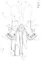
figure 1 is a diagrammatic view of a gas turbine plant for the production of electric power according to the present invention; -
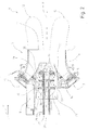
figure 2 is a section view, with parts removed for clarity, of a burner assembly according to a first embodiment; -
figure 3 is a section view, with parts removed for clarity, of a burner assembly according to a second embodiment; -
figure 4 is a section view, with parts removed for clarity, of a burner assembly according to a third embodiment; -
figure 5 is a section view, with parts removed for clarity, of a burner assembly according to a fourth embodiment; -
figure 6 is a section view, with parts removed for clarity, of a burner assembly according to a fifth embodiment. - In
figure 1 , numeral 1 indicates a plant for the production of electric power comprising agas turbine 2, which extends along an axis A, acompressor 3, acombustion chamber 4, an assembly 6 for supplying fuel to thecombustion chamber 4 and a generator 7, which transforms mechanical power provided by thegas turbine 2 into output electric power. - The
combustion chamber 4 is of the annular type and comprises a plurality of seats 8, each of which is adapted to be engaged by a burner assembly 9 (shown in greater detail infigures 2-6 ). Seats 8 are arranged along a circular path close to a peripheral edge ofcombustion chamber 4. There are twenty-four seats 8 andburner assemblies 9 in the non-limitative example shown herein. - With reference to
figure 2 , eachburner assembly 9 extends along an axis B and comprises amain burner 10 and anauxiliary burner 11. Theauxiliary burner 11 substantially extends along axis B, while themain burner 10 extends about theauxiliary burner 11 parallel to axis B. -
Main burner 10 is configured to supply an air-fuel mixture and to define a main combustion zone 12 (diagrammatically indicated by a dashed line in the figure). - Air and fuel are supplied along a supplying direction D1 directed towards the inside of
combustion chamber 4. - In particular,
main burner 10 comprises an annularair supply pipe 13 and an annularfuel supply pipe 14. - The annular
air supply pipe 13 receives air fromcompressor 3 and has a radial height decreasing in the supplying direction D1 so as to define a pipe having a substantially frustoconical shape. - The annular
fuel supply pipe 14 extends parallel to axis B and ends with a plurality ofnozzles 15, which directly face the annularair supply pipe 13. In particular, thenozzles 15 are organized in groups of nozzles aligned and inclined with respect to axis B. The groups ofnozzles 15 preferably comprise four or five nozzles. - At an
end portion 16, the annularair supply pipe 13 is provided with acylindrical outlet element 17, commonly named cylindrical Burner Outlet", which extends parallel to axis B. - The
main combustion zone 12, in which the combustion of the air-fuel mixture from the annularair supply pipe 13 occurs, extends close to theend portion 16 of the annularair supply pipe 13 and to thecylindrical outlet element 12. -
Auxiliary burner 11 is designed to cause a combustion process in anauxiliary combustion zone 19 and to supply themain combustion zone 12 with fumes produced by the combustion process in theauxiliary combustion zone 19. - In particular,
auxiliary burner 11 is designed to cause a combustion process of the flameless type in theauxiliary combustion zone 19. - Flameless combustion process means a combustion process obtained by preheating the combustion air and recirculating burnt gases. The air preheating conditions are obtained by recirculating the fumes. Thereby, indeed, the heat is transferred from the products to the reactants and the comburent is diluted with fuel and combustion products.
- Due to these conditions, a homogeneous combustion reaction may be developed within an auxiliary combustion zone, not being concentrated on a flame front. This determines a homogenous temperature in the auxiliary combustion zone, which in turn results in a reduction of the temperature peaks responsible for the formation of nitrogen oxides (NOx) of thermal origin.
- The definition of "flameless" derives from the absence of a defined, visible flame during the combustion reaction.
- Various embodiments of the burner assembly will be described below, each of which has a different auxiliary burner shape. These embodiments are described by way of mere non-limitative example. In fact, there are further embodiments of the auxiliary burner adapted to cause a flameless combustion process in an auxiliary combustion zone and to supply the
main combustion zone 12 with the fumes produced by the combustion process in the auxiliary combustion zone. - According to the first embodiment,
burner assembly 9 comprises anauxiliary burner 11 provided with aprimary channel 20 for supplying air, asecondary channel 21 for supplying air, afuel supplying channel 22 and aflow guiding device 23. - The
primary channel 20 and thesecondary channel 21 are supplied with air fromcompressor 3. Thefuel supplying channel 22 is preferably supplied with gas. - The
secondary channel 21 substantially extends along axis B, thefuel supplying channel 22 extends about thesecondary channel 21 parallel to axis B, while theprimary channel 20 extends about thefuel supplying channel 22 parallel to axis B. - The
flow guiding device 23 is arranged along theprimary channel 20 substantially at theauxiliary combustion zone 19 and is designed to produce at least one localized recirculation of combustion fumes in theauxiliary combustion zone 19. - In particular, the
flow guiding device 23 comprises afirst partition 26, asecond partition 27 and a third partition 28, which are arranged along theprimary pipe 20 and projects from theouter wall 29 of thefuel supplying channel 22 in a direction substantially perpendicular to axis B.First partition 26,second partition 27 and third partition 28 are arranged in sequence at a given distance from one another along the supplying direction D1, so as to define, along with theouter wall 29 of thefuel supplying channel 22, a first recirculation area 30 (as shown by the arrows infigure 2 ) of theauxiliary combustion zone 19 between thefirst partition 26 and thesecond partition 27, and a second recirculation area 31 (as shown by the arrows infigure 2 ) in theauxiliary combustion zone 19 betweensecond partition 27 and third partition 28. Thefirst recirculation area 30 and thesecond recirculation area 31 are open and communicate with theprimary channel 20. -
First partition 26,second partition 27 and third partition 28 are hollow and fluidically connected to thefuel supplying channel 22. In particular, the third partition 28 is also fluidically connected to thesecondary channel 21 and has a substantiallycircular bottom face 33, which is provided withoutlet holes 34 for the air from thesecondary channel 21. -
Second partition 27 and third partition 28 are provided with respectivefuel inlet ports first recirculation area 30 and thesecond recirculation area 31 of theauxiliary combustion zone 19, respectively. - The
outer wall 29 of thefuel supplying channel 22 is provided with at least two air inlet ports 37 communicating with thesecondary channel 21 and adapted to supply air to thefirst recirculation area 30 and to thesecond recirculation area 31, respectively. - The
flow guiding device 23 is preferably provided with abaffle 38 arranged upstream of thefirst partition 26 along the supplying direction D1. Theflow guiding device 23 is shaped so as to convey the air flow flowing along theprimary channel 20 towards thefirst recirculation area 30 and thesecond recirculation area 31. - In essence, the air from the
primary channel 20, the air from thesecondary channel 21 and the fuel from thefuel supplying channel 22 flow into thefirst recirculation area 30 and into thesecond recirculation area 31. -
Figure 3 shows a second embodiment of aburner assembly 39 in which the same reference numbers are used to describe parts similar to those of theburner assembly 9 infigure 2 . - According to such an embodiment,
burner assembly 39 comprises anauxiliary burner 41 provided with aprimary channel 42 for supplying air, asecondary channel 43 for supplying air, afuel supplying channel 44 and aflow guiding device 45.Primary channel 42 andsecondary channel 43 are supplied with air fromcompressor 3. Thefuel supplying channel 44 is preferably supplied with gas. - The
secondary channel 43 substantially extends along axis B, thefuel supplying channel 44 extends about thesecondary channel 43 parallel to axis B, while theprimary channel 42 extends about thefuel supplying channel 44 parallel to axis B. - The
flow guiding device 45 is arranged along theprimary channel 42, substantially at anauxiliary combustion zone 47 and is designed to produce at least one localized recirculation of combustion fumes in theauxiliary combustion zone 47. - In particular, the
flow guiding device 45 comprises afirst partition 49 and asecond partition 50 arranged along theprimary channel 42.First partition 49 projects from theouter wall 51 of thefuel supplying channel 44 in a direction substantially orthogonal to axis B,second partition 50 projects from theouter wall 51 of thesecondary channel 43 in a direction substantially orthogonal to axisB. First partition 49 andsecond partition 50 are arranged in sequence at a given distance from each other along the supplying direction D1 so as to define, along with theouter wall 52 of thesecondary channel 43, a circulation area 54 (as shown by the arrows infigure 3 ) of theauxiliary combustion zone 47 betweenfirst partition 49 andsecond partition 50. -
First partition 49 andsecond partition 50 are hollow and fluidically connected to thesecondary channel 43. Furthermore,first partition 49 has at least onefuel inlet port 55 fluidically connected to thefuel supplying channel 44, while thesecond partition 50 has at least oneair inlet port 56 for supplying therecirculation area 54 with the air flowing into thesecondary channel 43 -
Air inlet port 56 andfuel inlet port 55 are arranged so as to produce a double recirculation of the combustion fumes in the circulation area 54 (as shown by the arrows infigure 3 ). - The
flow guiding device 45 is preferably provided with abaffle 58 arranged substantially facing thefirst partition 49 in contact with theinner face 59 of theprimary channel 42 and shaped so as to convey the air flow flowing along theprimary channel 42 towards theauxiliary combustion zone 47. - In essence, the air from the
primary channel 42, the air from thesecondary channel 43 and the fuel from thefuel supplying channel 44 flow into theauxiliary recirculation area 47. -
Figure 4 shows a third embodiment of aburner assembly 59 in which the same reference numbers are used to describe parts similar to those of theburner assembly 9 infigure 2 . - According to the such an embodiment,
burner assembly 59 comprises anauxiliary burner 61 provided with aprimary channel 62 for supplying air, asecondary channel 63 for supplying air, afuel supplying channel 64 and aflow guiding device 65.Primary channel 62 andsecondary channel 63 are supplied with air fromcompressor 3. Thefuel supplying channel 64 is preferably supplied with gas. - The
secondary channel 63 substantially extends along axis B, thefuel supplying channel 64 extends about thesecondary channel 63 parallel to axis B, while theprimary channel 62 extends about thefuel supplying channel 64 parallel to axis B. - The
secondary channel 63 and thefuel supplying channel 64 are shaped so as to define theflow guiding device 65. - In the embodiment described and illustrated herein, the
flow guiding device 65 is a cup-shaped element, preferably having a paraboloid shape, arranged substantially along axis B at theend portion 16 of the annularair supply pipe 13. The cup-shapedelement 65 defines the auxiliary combustion zone 69 in which arecirculation area 70 of the combustion fumes produced in themain combustion zone 12 and of the combustion fumes produced in the auxiliary combustion zone 69 is generated, due to the shape of the cup-shapedelement 65 and to the proximity to the main combustion zone 12 (as shown by the arrows infigure 4 ). - The cup-shaped
element 65 is provided with at least onefuel inlet port 71 directly connected to thefuel supplying channel 64. The cup-shapedelement 65 is preferably provided with a plurality offuel inlet ports 71, which are calibrated and arranged so as to determine a sufficient penetration of fuel in therecirculation area 70. Thereby, the fuel may be adequately mixed to the fumes in therecirculation area 70 before the combustion reaction occurs. - The
wall 73 defining the cup-shapedelement 65 is hollow and cooled with the air flowing in thesecondary pipe 63.Wall 73 is open at the outer edge of the cup-shaped element so as to defineair inlet ports 74. Theair inlet ports 74 supply therecirculation area 70 with the air from thesecondary channel 63. -
Figure 5 shows a fourth embodiment of aburner assembly 79 in which the same reference numbers are used to describe parts similar to those of theburner assembly 9 infigure 2 . - According to such an embodiment,
burner assembly 79 comprises anauxiliary burner 81 provided with acentral nozzle 82 for supplying diesel fuel and arranged along axis B, a fuel (preferably gas) supplyingchannel 83, which extends about thecentral nozzle 82 parallel to axis B, and aprimary channel 84 for supplying air, which extends about thefuel supplying channel 83 parallel to axis B and aflow guiding device 85. - The air flowing in the
secondary channel 84 comes fromcompressor 3. The fuel flowing in thefuel supplying channel 83 is preferably gas. - The
flow guiding device 85 is arranged along theprimary channel 84 and comprises an airflow deflecting element 86 and a fuelflow channeling element 87. In detail, the airflow deflecting element 86 is annular and comprises arear portion 88 on which the air flow strikes and afront portion 89. - The
rear portion 88 is shaped so as to convey the air flow into twofast flow channels 90, which are defined by thewalls 91 of theprimary channel 84 and by therear portion 88. Thefront portion 89 is defined by anannular tongue 92, which extends parallel to axis B and has anend edge 93, which extends substantially orthogonal to axis B. Theend edge 93, theannular tongue 92 and therear portion 88 define anannular seat 95. - The fuel
flow conveying element 87 comprises a substantially frustoconical element, which extends about thefuel supplying channel 83 and is shaped so as to define afuel outlet chamber 97, and afuel conveying channel 98 to convey the fuel from theoutlet chamber 97 to theannular seat 95. - Deflecting
element 86, conveyingelement 87 andwalls 91 of theprimary channel 84 define theauxiliary combustion zone 100. In particular, the shape of deflectingelement 86 and conveyingelement 87 determines afume circulation area 101 substantially at the annular seat 95 (as shown by the arrows infigure 5 ). -
Figure 6 shows a fifth embodiment of aburner assembly 109 in which the same reference numbers are used to describe parts similar to those of theburner assembly 9 infigure 2 . - According to such an embodiment,
burner assembly 109 comprises anauxiliary burner 111 provided with acentral nozzle 112 for supplying diesel fuel and arranged along axis B, anair supplying channel 113, which extends about thecentral nozzle 112 parallel to axis B, afuel supplying channel 114, which substantially extends about theprimary channel 113 parallel to axis B (only partially seen infigure 6 ), and aflow guiding device 115. - The air flowing in the
secondary channel 113 comes fromcompressor 3. The fuel flowing in thefuel supplying channel 114 is preferably gas. - The
flow guiding device 115 is arranged along theprimary channel 113 and comprises a first baffle 117 and asecond baffle 118 having a substantially C-shaped section. - In particular, first baffle 117 and
second baffle 118 are arranged with respect to each other so as to form a flow path comprising in sequence a firstaxial segment 119, defined by the first baffle 117 and by aninner wall 116 of theprimary channel 113, a firstradial segment 120, a secondaxial segment 121 defined by the first and second baffles 117,118, a secondradial segment 122 and a thirdaxial segment 123 defined by thesecond baffle 118 and by the otherinner wall 124 of theprimary channel 113. - The
flow guiding device 115 comprises afuel inlet port 126 made in thewall 116 of theprimary channel 113, which faces along the firstaxial segment 119 of the flow path. - The first and second baffles 117,118 are shaped to define an
auxiliary combustion zone 127 at the secondaxial segment 121 of the flow path. In particular, the shape of the first and second baffles 117,118 causes the generation of a fume recirculation area 128 (as shown by the arrows infigure 6 ) substantially at the secondaxial segment 121 of the flow path. - The
auxiliary burner - Furthermore, the
burner assembly - The
burner assembly - It is finally apparent that changes and variations may be made to the
burner assembly
Claims (11)
- Burner assembly for a gas turbine plant, the burner assembly (9; 39; 59; 79; 109) extending along a longitudinal axis (B) and comprising:a main burner (10) configured to supply an air-fuel mixture and to define a main combustion zone (12);an auxiliary burner (11; 41; 61; 81; 111) configured to cause a flameless combustion process in an auxiliary combustion zone (19; 47; 69; 100; 127) and to supply the main combustion zone (12) with fumes produced by the flameless combustion process in the auxiliary combustion zone (19; 47; 69; 100; 127).
- Burner assembly according to claim 1, wherein the auxiliary combustion zone (19; 47; 69; 100; 127) is arranged upstream the main combustion zone (12) along an air supplying direction (D1).
- Burner assembly according to claim 2, wherein the auxiliary burner (11; 41; 61; 81; 111) comprises a flow guiding device (23; 45; 65; 85; 115) configured to cause at least a recirculation area (30, 31; 54; 70; 101; 128) of the fumes produced by the flameless combustion process in the auxiliary combustion zone (19; 47; 69; 100; 127) .
- Burner assembly according to claim 3, wherein the flow guiding device (23; 45; 65; 85; 115) is provided with at least an air inlet port (37; 56; 74; 90; 119) and at least a fuel inlet port (35, 36; 55; 71; 85; 126).
- Burner assembly according to anyone of the foregoing Claims, wherein the auxiliary burner (11; 41; 61; 81; 111) comprises a primary channel (20; 42; 62; 84; 113) for supplying air and a fuel supplying channel (22; 44; 64; 83; 114) .
- Burner assembly according to claim 5, wherein the auxiliary burner (11; 41; 61) comprises a secondary channel (21;43;63) for supplying air.
- Burner assembly according to any one of claims from 3 to 6, wherein the flow guiding device (23; 45) comprises at least a first partition (26, 27; 49) and a second partition (27, 28; 50), which extend transversely to the axis (B); the first partition (26, 27; 49) and the second partition (27, 28; 50) defining at least a recirculation area (30, 31; 54) of the auxiliary combustion zone (19; 47).
- Burner assembly according to any one of claims from 3 to 6, wherein the flow guiding device (115) comprises a first baffle (117) and a second baffle (118) having a C-shaped section; the first baffle (117) and the second baffle (118) being arranged with respect to one another so as to form a flow path comprising, in order, a first axial section (119), a first radial section (120), a second axial section (121), a second radial section (122) and a third axial section (123); the flow path comprising a recirculation area (128) of the auxiliary combustion zone (127).
- Burner assembly according to any one of claims from 3 to 6, wherein the flow guiding device (65) comprises a cup-shaped element arranged substantially along the axis (B), which defines a recirculation area (70) of the fumes produced by the combustion in the main combustion zone (12) and the fumes produced by the flameless combustion process in the auxiliary combustion zone (69).
- Burner assembly according to any one of claims from 3 to 6, wherein the flow guiding device (85) comprises a deflecting element (86) for deflecting the air flow and a conveying element (87) for conveying the fuel flow; the deflecting element (86) and the conveying element (87) being shaped in such a way to define a recirculation area (101) of the auxiliary combustion zone (100).
- Gas turbine electric power plant comprising at least a burner assembly (9; 39; 59; 79; 109) according to anyone of the foregoing claims.
Applications Claiming Priority (1)
| Application Number | Priority Date | Filing Date | Title |
|---|---|---|---|
| ITMI2009A002321A IT1397215B1 (en) | 2009-12-29 | 2009-12-29 | BURNER ASSEMBLY FOR A GAS TURBINE SYSTEM AND A GAS TURBINE SYSTEM INCLUDING THE BURNER ASSEMBLY |
Publications (3)
| Publication Number | Publication Date |
|---|---|
| EP2354662A2 true EP2354662A2 (en) | 2011-08-10 |
| EP2354662A3 EP2354662A3 (en) | 2013-07-03 |
| EP2354662B1 EP2354662B1 (en) | 2017-04-26 |
Family
ID=42224570
Family Applications (1)
| Application Number | Title | Priority Date | Filing Date |
|---|---|---|---|
| EP10197322.0A Active EP2354662B1 (en) | 2009-12-29 | 2010-12-29 | Burner assembly for a gas turbine plant and a gas turbine plant comprising said burner assembly |
Country Status (2)
| Country | Link |
|---|---|
| EP (1) | EP2354662B1 (en) |
| IT (1) | IT1397215B1 (en) |
Cited By (2)
| Publication number | Priority date | Publication date | Assignee | Title |
|---|---|---|---|---|
| WO2015062962A1 (en) * | 2013-10-31 | 2015-05-07 | Siemens Aktiengesellschaft | Gas turbine burner hub with pilot burner |
| WO2016162248A1 (en) * | 2015-04-08 | 2016-10-13 | Siemens Aktiengesellschaft | Burner arrangement |
Citations (4)
| Publication number | Priority date | Publication date | Assignee | Title |
|---|---|---|---|---|
| EP0193838A2 (en) | 1985-03-04 | 1986-09-10 | Siemens Aktiengesellschaft | Burner disposition for combustion installations, especially for combustion chambers of gas turbine installations, and method for its operation |
| DE19757617A1 (en) | 1997-12-23 | 1999-03-25 | Siemens Ag | Combustion system |
| EP1277920A1 (en) | 2001-07-19 | 2003-01-22 | Siemens Aktiengesellschaft | Procedure for operating a combuster of a gas-turbine and power plant |
| EP1649219A1 (en) | 2003-07-25 | 2006-04-26 | Ansaldo Energia S.P.A. | Gas turbine burner |
Family Cites Families (3)
| Publication number | Priority date | Publication date | Assignee | Title |
|---|---|---|---|---|
| AU681271B2 (en) * | 1994-06-07 | 1997-08-21 | Westinghouse Electric Corporation | Method and apparatus for sequentially staged combustion using a catalyst |
| EP1532400B1 (en) * | 2002-08-30 | 2017-07-26 | Ansaldo Energia Switzerland AG | Method and device for combusting a fuel-oxidising agent mixture |
| EP2107313A1 (en) * | 2008-04-01 | 2009-10-07 | Siemens Aktiengesellschaft | Fuel staging in a burner |
-
2009
- 2009-12-29 IT ITMI2009A002321A patent/IT1397215B1/en active
-
2010
- 2010-12-29 EP EP10197322.0A patent/EP2354662B1/en active Active
Patent Citations (4)
| Publication number | Priority date | Publication date | Assignee | Title |
|---|---|---|---|---|
| EP0193838A2 (en) | 1985-03-04 | 1986-09-10 | Siemens Aktiengesellschaft | Burner disposition for combustion installations, especially for combustion chambers of gas turbine installations, and method for its operation |
| DE19757617A1 (en) | 1997-12-23 | 1999-03-25 | Siemens Ag | Combustion system |
| EP1277920A1 (en) | 2001-07-19 | 2003-01-22 | Siemens Aktiengesellschaft | Procedure for operating a combuster of a gas-turbine and power plant |
| EP1649219A1 (en) | 2003-07-25 | 2006-04-26 | Ansaldo Energia S.P.A. | Gas turbine burner |
Cited By (4)
| Publication number | Priority date | Publication date | Assignee | Title |
|---|---|---|---|---|
| WO2015062962A1 (en) * | 2013-10-31 | 2015-05-07 | Siemens Aktiengesellschaft | Gas turbine burner hub with pilot burner |
| US20160252254A1 (en) * | 2013-10-31 | 2016-09-01 | Siemens Aktiengesellschaft | Gas turbine burner hub with pilot burner |
| WO2016162248A1 (en) * | 2015-04-08 | 2016-10-13 | Siemens Aktiengesellschaft | Burner arrangement |
| RU2669439C1 (en) * | 2015-04-08 | 2018-10-11 | Сименс Акциенгезелльшафт | Burner system |
Also Published As
| Publication number | Publication date |
|---|---|
| IT1397215B1 (en) | 2013-01-04 |
| EP2354662A3 (en) | 2013-07-03 |
| ITMI20092321A1 (en) | 2011-06-30 |
| EP2354662B1 (en) | 2017-04-26 |
Similar Documents
| Publication | Publication Date | Title |
|---|---|---|
| JP5374404B2 (en) | Combustion burner and boiler equipped with this combustion burner | |
| EP3679300B1 (en) | Gas turbine combustor assembly with a trapped vortex feature and method of operating a gas turbine combustor | |
| JP6972004B2 (en) | Split-type annular combustion system with multi-stage fuel in the axial direction | |
| US5836164A (en) | Gas turbine combustor | |
| EP1985926B1 (en) | Combustion equipment and combustion method | |
| JP6894447B2 (en) | Integrated combustor nozzle for split annular combustion system | |
| US6374615B1 (en) | Low cost, low emissions natural gas combustor | |
| US8256226B2 (en) | Radial lean direct injection burner | |
| EP2754963A1 (en) | Gas turbine combustor | |
| EP2107300A1 (en) | Swirler with gas injectors | |
| US10215417B2 (en) | Sequential combustor arrangement with a mixer | |
| KR20150074155A (en) | Sequential combustion with dilution gas mixer | |
| CN104685297A (en) | Flamesheet combustor dome | |
| CN101294715A (en) | Combustion device and combustion method of burner | |
| JP2015132462A (en) | Sequential combustion arrangement with dilution gas | |
| US12385431B2 (en) | Industrial premixed gas combustor using internal exhaust gas recirculation and operating method thereof | |
| KR20170073104A (en) | Burner for reducing nox and high efficiency and combstion equipment having the same | |
| EP3719396B1 (en) | Multi-tube through-flow boiler device | |
| KR102096434B1 (en) | Combustor | |
| US11300052B2 (en) | Method of holding flame with no combustion instability, low pollutant emissions, least pressure drop and flame temperature in a gas turbine combustor and a gas turbine combustor to perform the method | |
| US7430970B2 (en) | Burner with center air jet | |
| EP2354662B1 (en) | Burner assembly for a gas turbine plant and a gas turbine plant comprising said burner assembly | |
| JP2016023916A (en) | Gas turbine combustor | |
| CN105121962A (en) | Continuous combustion with diluent gas | |
| KR102336283B1 (en) | Vortex Recirculation Combustion Burner Head |
Legal Events
| Date | Code | Title | Description |
|---|---|---|---|
| PUAI | Public reference made under article 153(3) epc to a published international application that has entered the european phase |
Free format text: ORIGINAL CODE: 0009012 |
|
| AK | Designated contracting states |
Kind code of ref document: A2 Designated state(s): AL AT BE BG CH CY CZ DE DK EE ES FI FR GB GR HR HU IE IS IT LI LT LU LV MC MK MT NL NO PL PT RO RS SE SI SK SM TR |
|
| AX | Request for extension of the european patent |
Extension state: BA ME |
|
| PUAL | Search report despatched |
Free format text: ORIGINAL CODE: 0009013 |
|
| AK | Designated contracting states |
Kind code of ref document: A3 Designated state(s): AL AT BE BG CH CY CZ DE DK EE ES FI FR GB GR HR HU IE IS IT LI LT LU LV MC MK MT NL NO PL PT RO RS SE SI SK SM TR |
|
| AX | Request for extension of the european patent |
Extension state: BA ME |
|
| RIC1 | Information provided on ipc code assigned before grant |
Ipc: F23R 3/34 20060101AFI20130524BHEP |
|
| 17P | Request for examination filed |
Effective date: 20131227 |
|
| RBV | Designated contracting states (corrected) |
Designated state(s): AL AT BE BG CH CY CZ DE DK EE ES FI FR GB GR HR HU IE IS IT LI LT LU LV MC MK MT NL NO PL PT RO RS SE SI SK SM TR |
|
| GRAP | Despatch of communication of intention to grant a patent |
Free format text: ORIGINAL CODE: EPIDOSNIGR1 |
|
| INTG | Intention to grant announced |
Effective date: 20161114 |
|
| GRAS | Grant fee paid |
Free format text: ORIGINAL CODE: EPIDOSNIGR3 |
|
| GRAA | (expected) grant |
Free format text: ORIGINAL CODE: 0009210 |
|
| AK | Designated contracting states |
Kind code of ref document: B1 Designated state(s): AL AT BE BG CH CY CZ DE DK EE ES FI FR GB GR HR HU IE IS IT LI LT LU LV MC MK MT NL NO PL PT RO RS SE SI SK SM TR |
|
| REG | Reference to a national code |
Ref country code: GB Ref legal event code: FG4D |
|
| REG | Reference to a national code |
Ref country code: CH Ref legal event code: EP |
|
| REG | Reference to a national code |
Ref country code: AT Ref legal event code: REF Ref document number: 888222 Country of ref document: AT Kind code of ref document: T Effective date: 20170515 |
|
| REG | Reference to a national code |
Ref country code: IE Ref legal event code: FG4D |
|
| REG | Reference to a national code |
Ref country code: DE Ref legal event code: R096 Ref document number: 602010041824 Country of ref document: DE |
|
| REG | Reference to a national code |
Ref country code: DE Ref legal event code: R082 Ref document number: 602010041824 Country of ref document: DE Representative=s name: LOUIS, POEHLAU, LOHRENTZ, DE |
|
| REG | Reference to a national code |
Ref country code: NL Ref legal event code: MP Effective date: 20170426 |
|
| REG | Reference to a national code |
Ref country code: LT Ref legal event code: MG4D |
|
| REG | Reference to a national code |
Ref country code: AT Ref legal event code: MK05 Ref document number: 888222 Country of ref document: AT Kind code of ref document: T Effective date: 20170426 |
|
| PG25 | Lapsed in a contracting state [announced via postgrant information from national office to epo] |
Ref country code: NL Free format text: LAPSE BECAUSE OF FAILURE TO SUBMIT A TRANSLATION OF THE DESCRIPTION OR TO PAY THE FEE WITHIN THE PRESCRIBED TIME-LIMIT Effective date: 20170426 |
|
| PG25 | Lapsed in a contracting state [announced via postgrant information from national office to epo] |
Ref country code: NO Free format text: LAPSE BECAUSE OF FAILURE TO SUBMIT A TRANSLATION OF THE DESCRIPTION OR TO PAY THE FEE WITHIN THE PRESCRIBED TIME-LIMIT Effective date: 20170726 Ref country code: FI Free format text: LAPSE BECAUSE OF FAILURE TO SUBMIT A TRANSLATION OF THE DESCRIPTION OR TO PAY THE FEE WITHIN THE PRESCRIBED TIME-LIMIT Effective date: 20170426 Ref country code: ES Free format text: LAPSE BECAUSE OF FAILURE TO SUBMIT A TRANSLATION OF THE DESCRIPTION OR TO PAY THE FEE WITHIN THE PRESCRIBED TIME-LIMIT Effective date: 20170426 Ref country code: HR Free format text: LAPSE BECAUSE OF FAILURE TO SUBMIT A TRANSLATION OF THE DESCRIPTION OR TO PAY THE FEE WITHIN THE PRESCRIBED TIME-LIMIT Effective date: 20170426 Ref country code: AT Free format text: LAPSE BECAUSE OF FAILURE TO SUBMIT A TRANSLATION OF THE DESCRIPTION OR TO PAY THE FEE WITHIN THE PRESCRIBED TIME-LIMIT Effective date: 20170426 Ref country code: LT Free format text: LAPSE BECAUSE OF FAILURE TO SUBMIT A TRANSLATION OF THE DESCRIPTION OR TO PAY THE FEE WITHIN THE PRESCRIBED TIME-LIMIT Effective date: 20170426 |
|
| PG25 | Lapsed in a contracting state [announced via postgrant information from national office to epo] |
Ref country code: SE Free format text: LAPSE BECAUSE OF FAILURE TO SUBMIT A TRANSLATION OF THE DESCRIPTION OR TO PAY THE FEE WITHIN THE PRESCRIBED TIME-LIMIT Effective date: 20170426 Ref country code: BG Free format text: LAPSE BECAUSE OF FAILURE TO SUBMIT A TRANSLATION OF THE DESCRIPTION OR TO PAY THE FEE WITHIN THE PRESCRIBED TIME-LIMIT Effective date: 20170726 Ref country code: RS Free format text: LAPSE BECAUSE OF FAILURE TO SUBMIT A TRANSLATION OF THE DESCRIPTION OR TO PAY THE FEE WITHIN THE PRESCRIBED TIME-LIMIT Effective date: 20170426 Ref country code: LV Free format text: LAPSE BECAUSE OF FAILURE TO SUBMIT A TRANSLATION OF THE DESCRIPTION OR TO PAY THE FEE WITHIN THE PRESCRIBED TIME-LIMIT Effective date: 20170426 Ref country code: IS Free format text: LAPSE BECAUSE OF FAILURE TO SUBMIT A TRANSLATION OF THE DESCRIPTION OR TO PAY THE FEE WITHIN THE PRESCRIBED TIME-LIMIT Effective date: 20170826 Ref country code: PL Free format text: LAPSE BECAUSE OF FAILURE TO SUBMIT A TRANSLATION OF THE DESCRIPTION OR TO PAY THE FEE WITHIN THE PRESCRIBED TIME-LIMIT Effective date: 20170426 |
|
| REG | Reference to a national code |
Ref country code: DE Ref legal event code: R097 Ref document number: 602010041824 Country of ref document: DE |
|
| PG25 | Lapsed in a contracting state [announced via postgrant information from national office to epo] |
Ref country code: SK Free format text: LAPSE BECAUSE OF FAILURE TO SUBMIT A TRANSLATION OF THE DESCRIPTION OR TO PAY THE FEE WITHIN THE PRESCRIBED TIME-LIMIT Effective date: 20170426 Ref country code: DK Free format text: LAPSE BECAUSE OF FAILURE TO SUBMIT A TRANSLATION OF THE DESCRIPTION OR TO PAY THE FEE WITHIN THE PRESCRIBED TIME-LIMIT Effective date: 20170426 Ref country code: RO Free format text: LAPSE BECAUSE OF FAILURE TO SUBMIT A TRANSLATION OF THE DESCRIPTION OR TO PAY THE FEE WITHIN THE PRESCRIBED TIME-LIMIT Effective date: 20170426 Ref country code: CZ Free format text: LAPSE BECAUSE OF FAILURE TO SUBMIT A TRANSLATION OF THE DESCRIPTION OR TO PAY THE FEE WITHIN THE PRESCRIBED TIME-LIMIT Effective date: 20170426 Ref country code: EE Free format text: LAPSE BECAUSE OF FAILURE TO SUBMIT A TRANSLATION OF THE DESCRIPTION OR TO PAY THE FEE WITHIN THE PRESCRIBED TIME-LIMIT Effective date: 20170426 |
|
| PG25 | Lapsed in a contracting state [announced via postgrant information from national office to epo] |
Ref country code: SM Free format text: LAPSE BECAUSE OF FAILURE TO SUBMIT A TRANSLATION OF THE DESCRIPTION OR TO PAY THE FEE WITHIN THE PRESCRIBED TIME-LIMIT Effective date: 20170426 Ref country code: IT Free format text: LAPSE BECAUSE OF FAILURE TO SUBMIT A TRANSLATION OF THE DESCRIPTION OR TO PAY THE FEE WITHIN THE PRESCRIBED TIME-LIMIT Effective date: 20170426 |
|
| PLBE | No opposition filed within time limit |
Free format text: ORIGINAL CODE: 0009261 |
|
| STAA | Information on the status of an ep patent application or granted ep patent |
Free format text: STATUS: NO OPPOSITION FILED WITHIN TIME LIMIT |
|
| 26N | No opposition filed |
Effective date: 20180129 |
|
| PG25 | Lapsed in a contracting state [announced via postgrant information from national office to epo] |
Ref country code: SI Free format text: LAPSE BECAUSE OF FAILURE TO SUBMIT A TRANSLATION OF THE DESCRIPTION OR TO PAY THE FEE WITHIN THE PRESCRIBED TIME-LIMIT Effective date: 20170426 |
|
| REG | Reference to a national code |
Ref country code: CH Ref legal event code: PL |
|
| GBPC | Gb: european patent ceased through non-payment of renewal fee |
Effective date: 20171229 |
|
| REG | Reference to a national code |
Ref country code: IE Ref legal event code: MM4A |
|
| PG25 | Lapsed in a contracting state [announced via postgrant information from national office to epo] |
Ref country code: LU Free format text: LAPSE BECAUSE OF NON-PAYMENT OF DUE FEES Effective date: 20171229 Ref country code: MT Free format text: LAPSE BECAUSE OF NON-PAYMENT OF DUE FEES Effective date: 20171229 |
|
| REG | Reference to a national code |
Ref country code: FR Ref legal event code: ST Effective date: 20180831 |
|
| REG | Reference to a national code |
Ref country code: BE Ref legal event code: MM Effective date: 20171231 |
|
| PG25 | Lapsed in a contracting state [announced via postgrant information from national office to epo] |
Ref country code: FR Free format text: LAPSE BECAUSE OF NON-PAYMENT OF DUE FEES Effective date: 20180102 Ref country code: IE Free format text: LAPSE BECAUSE OF NON-PAYMENT OF DUE FEES Effective date: 20171229 |
|
| PG25 | Lapsed in a contracting state [announced via postgrant information from national office to epo] |
Ref country code: CH Free format text: LAPSE BECAUSE OF NON-PAYMENT OF DUE FEES Effective date: 20171231 Ref country code: GB Free format text: LAPSE BECAUSE OF NON-PAYMENT OF DUE FEES Effective date: 20171229 Ref country code: BE Free format text: LAPSE BECAUSE OF NON-PAYMENT OF DUE FEES Effective date: 20171231 Ref country code: LI Free format text: LAPSE BECAUSE OF NON-PAYMENT OF DUE FEES Effective date: 20171231 |
|
| PG25 | Lapsed in a contracting state [announced via postgrant information from national office to epo] |
Ref country code: MC Free format text: LAPSE BECAUSE OF FAILURE TO SUBMIT A TRANSLATION OF THE DESCRIPTION OR TO PAY THE FEE WITHIN THE PRESCRIBED TIME-LIMIT Effective date: 20170426 Ref country code: HU Free format text: LAPSE BECAUSE OF FAILURE TO SUBMIT A TRANSLATION OF THE DESCRIPTION OR TO PAY THE FEE WITHIN THE PRESCRIBED TIME-LIMIT; INVALID AB INITIO Effective date: 20101229 |
|
| PG25 | Lapsed in a contracting state [announced via postgrant information from national office to epo] |
Ref country code: CY Free format text: LAPSE BECAUSE OF NON-PAYMENT OF DUE FEES Effective date: 20170426 |
|
| PG25 | Lapsed in a contracting state [announced via postgrant information from national office to epo] |
Ref country code: MK Free format text: LAPSE BECAUSE OF FAILURE TO SUBMIT A TRANSLATION OF THE DESCRIPTION OR TO PAY THE FEE WITHIN THE PRESCRIBED TIME-LIMIT Effective date: 20170426 |
|
| PG25 | Lapsed in a contracting state [announced via postgrant information from national office to epo] |
Ref country code: TR Free format text: LAPSE BECAUSE OF FAILURE TO SUBMIT A TRANSLATION OF THE DESCRIPTION OR TO PAY THE FEE WITHIN THE PRESCRIBED TIME-LIMIT Effective date: 20170426 |
|
| PG25 | Lapsed in a contracting state [announced via postgrant information from national office to epo] |
Ref country code: PT Free format text: LAPSE BECAUSE OF FAILURE TO SUBMIT A TRANSLATION OF THE DESCRIPTION OR TO PAY THE FEE WITHIN THE PRESCRIBED TIME-LIMIT Effective date: 20170426 |
|
| PG25 | Lapsed in a contracting state [announced via postgrant information from national office to epo] |
Ref country code: GR Free format text: LAPSE BECAUSE OF FAILURE TO SUBMIT A TRANSLATION OF THE DESCRIPTION OR TO PAY THE FEE WITHIN THE PRESCRIBED TIME-LIMIT Effective date: 20170426 |
|
| PG25 | Lapsed in a contracting state [announced via postgrant information from national office to epo] |
Ref country code: AL Free format text: LAPSE BECAUSE OF FAILURE TO SUBMIT A TRANSLATION OF THE DESCRIPTION OR TO PAY THE FEE WITHIN THE PRESCRIBED TIME-LIMIT Effective date: 20170426 |
|
| P01 | Opt-out of the competence of the unified patent court (upc) registered |
Effective date: 20240430 |
|
| PGFP | Annual fee paid to national office [announced via postgrant information from national office to epo] |
Ref country code: DE Payment date: 20251222 Year of fee payment: 16 |