EP2354902B1 - Berührungseingabeverfahren und Vorrichtung dafür - Google Patents
Berührungseingabeverfahren und Vorrichtung dafür Download PDFInfo
- Publication number
- EP2354902B1 EP2354902B1 EP10161665.4A EP10161665A EP2354902B1 EP 2354902 B1 EP2354902 B1 EP 2354902B1 EP 10161665 A EP10161665 A EP 10161665A EP 2354902 B1 EP2354902 B1 EP 2354902B1
- Authority
- EP
- European Patent Office
- Prior art keywords
- light
- module
- display module
- touch
- touch input
- Prior art date
- Legal status (The legal status is an assumption and is not a legal conclusion. Google has not performed a legal analysis and makes no representation as to the accuracy of the status listed.)
- Not-in-force
Links
Images


Classifications
-
- G—PHYSICS
- G06—COMPUTING OR CALCULATING; COUNTING
- G06F—ELECTRIC DIGITAL DATA PROCESSING
- G06F3/00—Input arrangements for transferring data to be processed into a form capable of being handled by the computer; Output arrangements for transferring data from processing unit to output unit, e.g. interface arrangements
- G06F3/01—Input arrangements or combined input and output arrangements for interaction between user and computer
- G06F3/03—Arrangements for converting the position or the displacement of a member into a coded form
- G06F3/041—Digitisers, e.g. for touch screens or touch pads, characterised by the transducing means
- G06F3/0412—Digitisers structurally integrated in a display
-
- G—PHYSICS
- G06—COMPUTING OR CALCULATING; COUNTING
- G06F—ELECTRIC DIGITAL DATA PROCESSING
- G06F3/00—Input arrangements for transferring data to be processed into a form capable of being handled by the computer; Output arrangements for transferring data from processing unit to output unit, e.g. interface arrangements
- G06F3/01—Input arrangements or combined input and output arrangements for interaction between user and computer
- G06F3/03—Arrangements for converting the position or the displacement of a member into a coded form
- G06F3/041—Digitisers, e.g. for touch screens or touch pads, characterised by the transducing means
- G06F3/042—Digitisers, e.g. for touch screens or touch pads, characterised by the transducing means by opto-electronic means
- G06F3/0428—Digitisers, e.g. for touch screens or touch pads, characterised by the transducing means by opto-electronic means by sensing at the edges of the touch surface the interruption of optical paths, e.g. an illumination plane, parallel to the touch surface which may be virtual
Definitions
- the present invention relates to a touch input method and a device thereof, and more particularly to a touch input method and a device thereof in which a displayed image content is used as a reference for determining touch information.
- a backlight module is used to produce a light source, and the transmittance of the backlight is changed by controlling the twist and deformation of the liquid crystal, in order to determine the brightness of the image displayed on the display.
- the LCD displays the image mainly using cold cathode fluorescent lamps (CCFL) or light-emitting diodes (LEDs) as the backlight thereof.
- CCFL cold cathode fluorescent lamps
- LEDs light-emitting diodes
- the currently available optic-type touch screens can be divided into out-cell and in-cell touch screens.
- the out-cell touch screen mainly uses two infrared light emitting units arranged at two corners of the screen to emit infrared light, and uses image acquisition units to acquire shades formed on reflection strips when the infrared lights are blocked by a touch object.
- a processor of the optic-type touch screen computes the shades to find out the position of the touch point. While the out-cell touch screen can be advantageously applied to a large-size touch display, the touch display adopting the out-cell design must have a predetermined mechanism thickness and therefore fails to be low-profile and light because the touch display must be provided with reflective strips.
- FIG. 1 schematically shows a surface of a conventional touch display 12.
- infrared LEDs 110 in a backlight source 11 emit invisible lights 111 having a fixed level of brightness.
- in-cell light sensors of the display 12 would detects reflected lights 112 of the invisible lights 111 reflected by the object 13, and when there is not any object above or on the surface of the touch display 12, the in-cell light sensors would output a no-detection response.
- EP 2144143 discloses an image input/output device and method of correcting photo-reception level in image input/output device, and method of inputting image.
- US 2006/038198 discloses a device and a method for producing output light having a wavelength spectrum in the visible range and the infrared range, using a fluorescent material.
- a first embodiment of the touch input method is applicable to a touch display, which includes a display module for displaying an image, a backlight module for emitting a light source, at least one light-sensing unit for sensing a reflected light of the light source reflected by at least one object on the display module and generating a light intensity signal correspondingly, and a processing module for receiving the light intensity signal and determining at least one touch point on the display module touched by the at least one object based on the received light intensity signal.
- the touch input method includes the steps of using the processing module to receive the image displayed on the display module, using the processing module to analyze the image and obtain an image analysis result; and using the processing module to regulate a light intensity of an invisible light emitted from the backlight module based on the image analysis result.
- an embodiment of the touch input device includes a display module, a backlight module, at least one light-sensing unit, and a processing module.
- the display module displays an image.
- the backlight module emits a light source.
- the light-sensing unit senses a reflected light of the light source reflected by at least one object on the display module and generates a light intensity signal correspondingly.
- the processing module is connected to the display module, the backlight module and the light-sensing unit, and the processing module receives the light intensity signal and determines at least one touch point on the display module touched by the at least one object based on the received light intensity signal.
- the processing module also receives the image displayed on the display module and analyzes the image to obtain an image analysis result, and regulates a light intensity of an invisible light emitted from the backlight module based on the image analysis result.
- a second embodiment of the touch input method is applicable to a touch display, which includes a display module for displaying an image, a backlight module for emitting a light source, at least one light-sensing unit for sensing a reflected light of the light source reflected by at least one object on the display module and generating a light intensity signal correspondingly, a storage unit for storing a threshold value, and a processing module for receiving the light intensity signal and the threshold value and comparing the received light intensity signal with the threshold value to determine at least one touch point on the display module touched by the at least one object.
- the touch input method includes the steps of using the processing module to receive the image displayed on the display module; using the processing module to analyze the image and obtain an image analysis result; and using the processing module to adjust the threshold value based on the image analysis result.
- another embodiment of the touch input device includes a display module, a backlight module, at least one light-sensing unit, a storage unit, and a processing module.
- the display module displays an image; the backlight module emits a light source; the light-sensing unit senses a reflected light of the light source reflected by at least one object on the display module and generates a light intensity signal correspondingly.
- the storage unit stores a threshold value.
- the processing module is connected to the display module, the backlight module, the storage unit and the light-sensing unit and the processing module receives the light intensity signal and the threshold value, and compares the received light intensity signal with the threshold value to determine at least one touch point on the display module touched by the at least one object.
- the processing module also receives the image displayed on the display module and analyzes the image to obtain an image analysis result, and adjusts the threshold value based on the image analysis result.
- the touch input method and the device thereof according to the present invention has one or more of the following advantages:
- Fig. 2 is a block diagram of a first embodiment of a touch input device 2 according to the present invention.
- the touch input device 2 in the first embodiment includes a display module 21, a backlight module 22, a light-sensing unit 23, and a processing module 24.
- the processing module 24 is electrically connected to the display module 21, the backlight module 22 and the light-sensing unit 23.
- the display module 21 is able to display an image, and is preferably a liquid crystal display (LCD) screen or an organic light emitting diode (OLED) screen.
- the backlight module 22 includes a visible light source 221 and an invisible light source 222.
- the backlight module 22 is arranged behind the display module 21 and can be a direct-lit backlight module or an edge-lit backlight module.
- the invisible light source 222 is preferably an infrared (IR) light emitted from an IR light emitting unit or an IR light emitted from a red light emitting unit having a relatively wider light spectrum.
- the visible light source 221 preferably includes red-light, green-light and blue-light LEDs emitting red light, green light and blue light, respectively.
- the display module 21 includes at least one filter unit 211 and at least one light-sensing unit 23.
- the filter unit 211 is able to absorb a visible light while the light-sensing unit 23 is able to receive an IR light.
- an IR light 2221 emitted from the invisible light source 222 of the backlight module 22 would be reflected by the object 26.
- the light-sensing unit 23 receives the reflected invisible light 2222 and generates a light intensity signal 231 according to the reflected IR light 2222.
- the light intensity signal 231 is sent to the processing module 24 .
- the light-sensing unit 23 can be arranged on the touch input device 2 at different positions without being limited to that shown in Fig. 3 . That is, in addition to being arranged inside the display module 21, the light-sensing unit 23 can be otherwise externally attached to the display module 21. And, an areal sensing can be achieved when a plurality of light-sensing units 23 is provided.
- the processing module 24 includes a touch data analysis unit 241 and an image analysis unit 242.
- the touch data analysis unit 241 can analyze according to the received light intensity signal 231 to obtain touch information, such as the number of touch points, touch positions, touch gestures, or touch height.
- the image analysis unit 242 is able to analyze according to the content of the image displayed on the display module 21 to obtain an image analysis result.
- the image analysis result is preferably an image gray level distribution analysis result or a red light distribution analysis result, so as to obtain the actual brightness of light or the actual light quantity of IR light transmitted from different zones of the display module 21.
- the image analysis unit 242 is able to conduct the red light distribution analysis, so as to obtain red light quantities and IR light quantities at different zones of the display module 21.
- the processing module 24 selects to increase or decrease the driving current or driving voltage of the red light emitting units at different zones. For example, for zones having relatively weak transmitted IR light quantities, the driving current or driving voltage of the red light emitting units thereat can be increased, and for zones having relatively high transmitted IR light quantities, the driving current or driving voltage of the red light emitting units thereat can be decreased, so that the IR lights reflected by the object in different zones of the display module can have the same reflected light intensity. In this manner, the object can perform the same touch movement at different zones. While the actual light quantities of transmitted IR lights at different zones are different to result in the generation of different light intensity signals by different sensing units 23, the processing module 24 can still regulate the IR light intensities to thereby make correct determination of the touch movement.
- the image analysis unit 242 can conduct the gray level distribution analysis, so as to obtain actual levels of brightness at different zones of the display module and further obtain the IR light quantities at different zones accordingly.
- the processing module 24 can regulate the driving voltage or current used to drive the IR light emitting units, so that the IR lights reflected by the touch object at different zones of the display module 21 can have the same reflected light intensity.
- the driving voltage or driving current of the above-mentioned red light emitting units or IR light emitting units can be regulated in three different ways.
- each of the red light emitting units or the IR light emitting units in the display module 21 is analyzed, so as to individually regulate the light quantity of the red light emitting unit or the IR light emitting unit in every pixel 212.
- the red light emitting units or the IR light emitting units in a specified zone are analyzed, as shown in Fig. 4A .
- the specified zone 213 comprises four (4) pixels 212 in a 2x2 array.
- the image analysis unit 242 conducts the red light analysis or the gray level analysis of the image in each individual specified zone, and finds an average of the red light quantity or the IR light quantity in the specified zone, so that the IR light quantity distribution in all specified zones is obtained and the driving voltage or driving current of the red light emitting units or the IR light emitting units within the same specified zone is increased or reduced at the same time.
- the third way only the red lights or the IR lights emitted from the pixels 212 located surrounding the position of a touch point 214 are analyzed, as shown in Fig. 4B , and only the driving current or driving voltage of the analyzed red light emitting units or the analyzed IR light emitting units is regulated. In the case of having multiple touch points 214, all the red light emitting units or the IR light emitting units corresponding to the touch points 214 are analyzed at the same time.
- Fig. 5 is a front view showing a second embodiment of the touch input device 2 according to the present invention.
- the second embodiment is different from the first embodiment in that, two light-sensing units 23 in the second embodiment are arranged at an upper left corner and an upper right corner of the display module 21.
- the light-sensing units 23 each have an angle of view wide enough for covering a large part of the display module 21.
- an additional light-sensing unit 23 can be provided on the display module 21 between the first two light-sensing units 23.
- the light-sensing units 23 receive the reflected IR lights 2222 to generate light intensity signals 231 to the touch data analysis unit 241, at where the above-mentioned touch information can be computed using the known triangle positioning algorithm.
- a surface of a display zone of the display module 21 and a space in front of the display zone are defined as a coordinate detection zone. Since all other structures of the second embodiment are similar to the first embodiment, they are not repeatedly described herein.
- Fig. 6 is a flowchart showing the steps included in a first embodiment of a touch input method according to the present invention.
- the touch input method is applicable to a touch display.
- the touch display includes a display module, a backlight module, at least one light-sensing unit, and a processing module.
- the display module is able to display an image
- the backlight module is able to emit a light source
- the light-sensing unit is able to sense a reflected light of the light source reflected by at least one object on the display module and generate a light intensity signal corresponding to the reflected light.
- a first step S10 of the touch input method according to the first embodiment as shown in Fig. 6 use the processing module to receive the light intensity signal.
- a second step S20 use the processing module to analyze according to the light intensity signal, so as to obtain information about the touch point.
- a third step S30 use the processing module to regulate a light intensity of an invisible light emitted from the backlight module based on an image analysis result.
- a fourth step S40 use the processing module to receive the light intensity signal for a second time and output a touch result according to the light intensity signal received the second time.
- Fig. 7 is a flowchart showing the steps for producing the image analysis result used in the third step S30.
- the steps include:
- Fig. 8 is a block diagram of a third embodiment of the touch input device 2 according to the present invention.
- the touch input device 2 of the third embodiment is different from the first embodiment in further having a storage unit 25 for storing a threshold value 251, and the processing module 24 adjusting the threshold value according to an image analysis result.
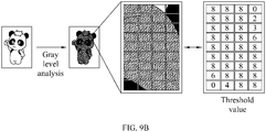
- the processing module 24 determines there is a touch object on a position corresponding to the light intensity signal 231, and the touch input device 2 would analyze the image content shown by the display module 21 and adjust the threshold value 251 accordingly, as shown in Figs. 9A and 9B .
- the image analysis unit 242 conducts an IR analysis of the displayed image.
- the touch data analysis unit 241 might make an improper determination when the same threshold value is set for the upper half and the lower half and the touch object is the same. Therefore, in the present invention, the threshold value is adjusted according to the IR analysis by reducing the threshold value corresponding to the displayed image content with dark colors and increasing the threshold value corresponding to the display content with light colors, so that the touch data analysis unit 241 can determine the correct touch result based on the light intensity signals generated corresponding to the reflected light intensities and the adjusted threshold values 251.
- Fig. 9B is different from Fig.
- the image analysis unit 242 transforms the displayed image content into different gray levels, so as to obtain a gray level distribution analysis result, based on which the processing module 24 regulates the threshold values 251 set for the light-sensing units 23 corresponding to the touch position. Since all other structures of the third embodiment are similar to the first embodiment, they are not repeatedly described herein.
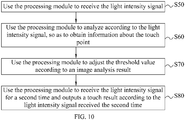
- Fig. 10 is a flowchart showing the steps included in a second embodiment of the touch input method according to the present invention.
- the touch input method in the second embodiment is different from the first embodiment in that the second embodiment is applicable to a touch display similar to that in the first embodiment but further including a storage unit for storing a threshold value.
- the processing module compares the received light intensity signal with the threshold value to determine the touch result. When the light intensity signal is larger than the threshold value, the processing module determines the object on the display module performs a touch movement; and when the light intensity signal is smaller than the threshold value, the processing module determines the object does not perform a touch movement.
- a first step S50 of the touch input method according to the second embodiment as shown in Fig. 10 use the processing module to receive the light intensity signal.
- a second step S60 use the processing module to analyze according to the light intensity signal, so as to obtain information about the touch point.
- a third step S70 use the processing module to adjust the threshold value according to an image analysis result.
- a fourth step S80 the processing module receives the light intensity signal for a second time and outputs a touch result according to the light intensity signal received the second time.
- the processing module regulates the intensity of the invisible light according to the image analysis result in order to make a correct determination of the touch movement.
- the processing module adjusts the threshold value instead of regulating the invisible light intensity. That is, in the second embodiment, while the light-sensing units generate different light intensity signals corresponding to different reflected light intensities, the processing module can still make a correct determination of the touch through comparison of the threshold values with the light intensity signals because the threshold values have already been adjusted by the processing module according to the image analysis result.
Landscapes
- Engineering & Computer Science (AREA)
- General Engineering & Computer Science (AREA)
- Theoretical Computer Science (AREA)
- Human Computer Interaction (AREA)
- Physics & Mathematics (AREA)
- General Physics & Mathematics (AREA)
- Position Input By Displaying (AREA)
- Liquid Crystal (AREA)
- Liquid Crystal Display Device Control (AREA)
- Control Of Indicators Other Than Cathode Ray Tubes (AREA)
Claims (16)
- Berührungseingabeverfahren für ein Touch-Display, wobei das Touch-Display ein Anzeigemodul (21) mit mehreren Pixeln (212), ein Hintergrundbeleuchtungsmodul (22), Lichterfassungseinheiten (23) und ein Verarbeitungsmodul (24) aufweist,wobei das Anzeigemodul (21) dazu geeignet ist, ein Bild darzustellen,das Hintergrundbeleuchtungsmodul (22) Quellen (222) für unsichtbares Licht aufweist, die dazu geeignet sind, unsichtbares Licht (111) zu emittieren,die Lichterfassungseinheiten (23) dazu geeignet sind, reflektiertes unsichtbares Licht, das durch die Quellen (222) für unsichtbares Licht emittiert und durch mindestens ein Objekt (26) auf dem Anzeigemodul (21) reflektiert wird, zu erfassen und ein entsprechendes Lichtintensitätssignal (231) zu erzeugen, unddas Verarbeitungsmodul dazu geeignet ist, das Lichtintensitätssignal (231) zu empfangen und basierend auf dem empfangenen Lichtintensitätssignal (231) mindestens einen durch das mindestens eine Objekt (26) berührten Berührungspunkt auf dem Anzeigemodul (21) zu bestimmen, wobei das Berührungseingabeverfahren die folgenden Schritte aufweist:Verwenden des Verarbeitungsmoduls (24) zum Empfangen des auf dem Anzeigemodul (21) dargestellten Bildes;gekennzeichnet durchVerwenden des Verarbeitungsmoduls (24) zum Analysieren des Bildes, um ein Bildanalyseergebnis für jedes Pixels (212) im Anzeigemodul, für spezifizierte Bereiche von Pixeln (212) oder für Pixel (212) zu erhalten, die in der Umgebung der Position des Berührungspunktes (214) angeordnet sind; undVerwenden des Verarbeitungsmoduls (24) zum Regeln der Lichtintensität des von den Quellen (222) für unsichtbares Licht des Hintergrundbeleuchtungsmoduls (22) emittierten unsichtbaren Lichts (111) gemäß dem Bildanalyseergebnis für jedes Pixel (212), für Bereiche von Pixeln (212) oder für Pixel (212), die in der Umgebung der Position des Berührungspunktes (214) angeordnet sind.
- Verfahren nach Anspruch 1, wobei das Bildanalyseergebnis eine Graustufenwertverteilungsanalyseergebnis ist.
- Verfahren nach Anspruch 1 oder 2, wobei das Hintergrundbeleuchtungsmodul (22) ferner mindestens eine rotes Licht emittierende Einheit, eine grünes Licht emittierende Einheit und eine blaues Licht emittierende Einheit aufweist, und wobei das unsichtbare Licht (111) zusätzlich von der rotes Licht emittierenden Einheit emittiert wird.
- Verfahren nach einem der Ansprüche 1 bis 3, wobei das Bildanalyseergebnis ein Verteilungsanalyseergebnis für rotes Licht ist.
- Berührungseingabevorrichtung (2), mit:einem Anzeigemodul (21), das dazu geeignet ist, ein Bild darzustellen;einem Hintergrundbeleuchtungsmodul (22) mit Quellen (222) für unsichtbares Licht, wobei die Quellen (222) für unsichtbares Licht dazu geeignet sind, unsichtbares Licht (111) zu emittieren,Lichterfassungseinheiten (23), die dazu geeignet sind, reflektiertes unsichtbares Licht, das durch die Quellen (222) für unsichtbares Licht emittiert und durch mindestens ein Objekt (26) auf dem Anzeigemodul (21) reflektiert wird, zu erfassen und ein entsprechendes Lichtintensitätssignal (231) zu erzeugen, undeinem Verarbeitungsmodul (24), das mit dem Anzeigemodul (21), dem Hintergrundbeleuchtungsmodul (22) und den Lichterfassungseinheiten (23) verbunden ist,wobei das Verarbeitungsmodul (24) dazu geeignet ist, das Lichtintensitätssignal (231) zu empfangen und basierend auf dem empfangenen Lichtintensitätssignal (231) mindestens einen durch das mindestens eine Objekt (26) berührten Berührungspunkt (214) auf dem Anzeigemodul (21) zu bestimmen;wobei das Verarbeitungsmodul (24) das auf dem Anzeigemodul (21) dargestellte Bild empfängt und das Bild analysiert, um ein Bildanalyseergebnis für jedes Pixel (212) im Anzeigemodul, für spezifizierte Bereiche von Pixeln (212) oder für Pixel (212) zu erhalten, die in der Umgebung der Position des Berührungspunktes (214) angeordnet sind, und die Lichtintensität von durch die Quellen (222) für unsichtbares Licht des Hintergrundbeleuchtungsmoduls (22) emittiertem unsichtbarem Licht (111) gemäß dem Bildanalyseergebnis für jedes Pixels (212), für Bereiche von Pixeln (212) oder für Pixel (212) reguliert, die in der Umgebung der Position des Berührungspunktes (214) angeordnet sind.
- Vorrichtung (2) nach Anspruch 5, wobei das unsichtbare Licht Infrarot(IR)licht ist.
- Vorrichtung (2) nach Anspruch 6, wobei das Hintergrundbeleuchtungsmodul (22) ferner mindestens eine Infrarot(IR)licht emittierende Einheit zum Emittieren des IR-Lichts (2221) aufweist.
- Vorrichtung (2) nach Anspruch 7, wobei das Hintergrundbeleuchtungsmodul (22) ferner mindestens eine rotes Licht emittierende Einheit, eine grünes Licht emittierende Einheit und eine blaues Licht emittierende Einheit aufweist, und wobei das IR-Licht (2221) zusätzlich durch die rotes Licht emittierende Einheit emittiert wird.
- Vorrichtung (2) nach einem der Ansprüche 5 bis 8, wobei die mindestens eine Lichterfassungseinheit (23) innerhalb des Hintergrundbeleuchtungsmoduls (22) angeordnet ist.
- Berührungseingabeverfahren, das auf ein Touch-Display anwendbar ist, wobei das Touch-Display ein Anzeigemodul (21), ein Hintergrundbeleuchtungsmodul (22), Lichterfassungseinheiten (23), eine Speichereinheit (25) und ein Verarbeitungsmodul (24) aufweist,wobei das Anzeigemodul (21) dazu geeignet ist, ein Bild darzustellen,das Hintergrundbeleuchtungsmodul (22) Quellen (222) für unsichtbares Licht aufweist,die Quellen (222) für unsichtbares Licht dazu geeignet sind, unsichtbares Licht (111) zu emittieren,die Lichterfassungseinheiten (23) dazu geeignet sind, reflektiertes Licht des durch die Quellen (222) für unsichtbares Licht emittierten und durch mindestens ein Objekt (26) auf dem Anzeigemodul (21) reflektierten unsichtbaren Lichts zu erfassen und ein entsprechendes Lichtintensitätssignal (231) zu erzeugen,die Speichereinheit (25) dazu geeignet ist, einen Schwellenwert (251) zu speichern, unddas Verarbeitungsmodul dazu geeignet ist, das Lichtintensitätssignal (231) und den Schwellenwert (251) zu empfangen und das Lichtintensitätssignal (231) mit dem Schwellenwert (251) zu vergleichen, um mindestens einen durch das mindestens eine Objekt (26) berührten Berührungspunkt (214) auf dem Anzeigemodul (21) zu bestimmen,wobei das Berührungseingabeverfahren die folgenden Schritte aufweist:Verwenden des Verarbeitungsmoduls (24) zum Empfangen des auf dem Anzeigemodul (21) dargestellten Bildes;gekennzeichnet durchVerwenden des Verarbeitungsmoduls (24) zum Analysieren des Bildes, um ein Bildanalyseergebnis für jedes Pixels (212) im Anzeigemodul, für spezifizierte Bereiche von Pixeln (212) oder für Pixel (212) zu erhalten, die in der Umgebung der Position des Berührungspunktes (214) angeordnet sind; undVerwenden des Verarbeitungsmoduls (24) zum Einstellen des Schwellenwertes (251) gemäß dem Bildanalyseergebnis für jedes Pixel (212), für Bereiche von Pixeln (212) oder für Pixel (212), die in der Umgebung der Position des Berührungspunktes (214) angeordnet sind.
- Verfahren nach Anspruch 10, wobei das Bildanalyseergebnis eine Graustufenwertverteilungsanalyseergebnis ist.
- Verfahren nach Anspruch 10, wobei das Bildanalyseergebnis ein Verteilungsanalyseergebnis für rotes Licht ist.
- Berührungseingabevorrichtung (2) mit:einem Anzeigemodul (21), das dazu geeignet ist, ein Bild darzustellen;einem Hintergrundbeleuchtungsmodul (22) mit Quellen (222) für unsichtbares Licht, die dazu geeignet sind, unsichtbares Licht (111) zu emittieren,mindestens einer Lichterfassungseinheit (23), die dazu geeignet sind, reflektiertes Licht des durch die Quellen (222) für unsichtbares Licht emittierten und durch mindestens ein Objekt (26) auf dem Anzeigemodul (21) reflektierten unsichtbaren Lichts zu erfassen und ein entsprechendes Lichtintensitätssignal (231) zu erzeugen,einer Speichereinheit (25), die dazu geeignet ist, einen Schwellenwert (251) zu speichern; undeinem Verarbeitungsmodul (24), das mit dem Anzeigemodul (21), dem Hintergrundbeleuchtungsmodul (22), den Lichterfassungseinheiten (23) und der Speichereinheit (25) verbunden ist,wobei das Verarbeitungsmodul (24) dazu geeignet ist, das Lichtintensitätssignal (231) und den Schwellenwert (251) zu empfangen und das Lichtintensitätssignal (231) mit dem Schwellenwert (251) zu vergleichen, um mindestens einen durch das mindestens eine Objekt (26) berührten Berührungspunkt (214) auf dem Anzeigemodul (21) zu bestimmen,wobei das Verarbeitungsmodul (24) das auf dem Anzeigemodul (21) dargestellte Bild empfängt und das Bild analysiert, um ein Bildanalyseergebnis für jedes Pixel (21) im Anzeigemodul, für spezifizierte Bereiche von Pixeln (212) oder für Pixel (212) zu erhalten, die in der Umgebung der Position des Berührungspunktes (214) angeordnet sind, und den Schwellenwert (251) gemäß dem Bildanalyseergebnis für jedes Pixel (212), für Bereiche von Pixeln (212) oder für Pixel (212), die in der Umgebung der Position des Berührungspunktes (214) angeordnet sind, einstellt.
- Vorrichtung (2) nach Anspruch 13, wobei das unsichtbare Licht (111) IR-Licht ist.
- Vorrichtung (2) nach Anspruch 14, wobei das Hintergrundbeleuchtungsmodul (22) ferner mindestens eine IR-Licht emittierende Einheit zum Emittieren von IR-Licht aufweist.
- Vorrichtung (2) nach Anspruch 15, wobei das Hintergrundbeleuchtungsmodul (22) ferner mindestens eine rotes Licht emittierende Einheit, eine grünes Licht emittierende Einheit und eine blaues Licht emittierende Einheit aufweist, und wobei das IR-Licht (2221) zusätzlich durch die rotes Licht emittierende Einheit emittiert wird.
Applications Claiming Priority (1)
| Application Number | Priority Date | Filing Date | Title |
|---|---|---|---|
| TW099102893A TWI442286B (zh) | 2010-02-01 | 2010-02-01 | 觸控式輸入方法及其裝置 |
Publications (3)
| Publication Number | Publication Date |
|---|---|
| EP2354902A2 EP2354902A2 (de) | 2011-08-10 |
| EP2354902A3 EP2354902A3 (de) | 2015-05-27 |
| EP2354902B1 true EP2354902B1 (de) | 2017-06-21 |
Family
ID=43901538
Family Applications (1)
| Application Number | Title | Priority Date | Filing Date |
|---|---|---|---|
| EP10161665.4A Not-in-force EP2354902B1 (de) | 2010-02-01 | 2010-04-30 | Berührungseingabeverfahren und Vorrichtung dafür |
Country Status (3)
| Country | Link |
|---|---|
| US (1) | US20110187653A1 (de) |
| EP (1) | EP2354902B1 (de) |
| TW (1) | TWI442286B (de) |
Families Citing this family (17)
| Publication number | Priority date | Publication date | Assignee | Title |
|---|---|---|---|---|
| TWI524239B (zh) * | 2010-10-08 | 2016-03-01 | 友達光電股份有限公司 | 判斷觸碰位置的方法 |
| TWI516994B (zh) * | 2011-03-15 | 2016-01-11 | 晨星半導體股份有限公司 | 多指觸控方法與相關裝置 |
| DE102012011256B4 (de) | 2012-06-05 | 2018-08-16 | Georg Witkowski | Eingabeelement für eine Datenverarbeitungsanordnung |
| TWI493406B (zh) * | 2013-04-24 | 2015-07-21 | Acer Inc | 電子裝置及其觸控偵測方法 |
| US9454265B2 (en) | 2013-09-23 | 2016-09-27 | Qualcomm Incorporated | Integration of a light collection light-guide with a field sequential color display |
| US20150084994A1 (en) * | 2013-09-23 | 2015-03-26 | Qualcomm Incorporated | Touch-enabled field-sequential color (fsc) display using a light guide with light turning features |
| US9741286B2 (en) | 2014-06-03 | 2017-08-22 | Apple Inc. | Interactive display panel with emitting and sensing diodes |
| US9570002B2 (en) * | 2014-06-17 | 2017-02-14 | Apple Inc. | Interactive display panel with IR diodes |
| US10713458B2 (en) | 2016-05-23 | 2020-07-14 | InSyte Systems | Integrated light emitting display and sensors for detecting biologic characteristics |
| US10931859B2 (en) * | 2016-05-23 | 2021-02-23 | InSyte Systems | Light emitter and sensors for detecting biologic characteristics |
| JP7062341B2 (ja) * | 2018-09-14 | 2022-05-06 | アルパイン株式会社 | 表示装置及び補正方法 |
| TWI707540B (zh) * | 2018-11-22 | 2020-10-11 | 達方電子股份有限公司 | 對光軸鍵盤進行光衰補償的方法 |
| CN109672436B (zh) * | 2018-12-12 | 2023-07-18 | 苏州达方电子有限公司 | 对光轴键盘进行光衰补偿的方法 |
| CN109672437B (zh) * | 2018-12-25 | 2023-07-18 | 苏州达方电子有限公司 | 一种光轴键盘 |
| US11188212B2 (en) * | 2020-03-19 | 2021-11-30 | Panasonic Intellectual Property Management Co., Ltd. | Methods and systems for monitoring objects for image-inspection |
| CN115904106B (zh) * | 2021-08-13 | 2024-03-26 | 安徽省东超科技有限公司 | 定位感测方法及输入终端装置 |
| TWI809916B (zh) | 2021-10-27 | 2023-07-21 | 達方電子股份有限公司 | 感應鍵盤及其感應按鍵 |
Family Cites Families (19)
| Publication number | Priority date | Publication date | Assignee | Title |
|---|---|---|---|---|
| JPH06342146A (ja) * | 1992-12-11 | 1994-12-13 | Canon Inc | 画像表示装置、半導体装置及び光学機器 |
| US20060038198A1 (en) * | 2004-08-23 | 2006-02-23 | Chua Janet B Y | Device and method for producing output light having a wavelength spectrum in the visible range and the infrared range using a fluorescent material |
| US7679672B2 (en) * | 2004-10-14 | 2010-03-16 | Avago Technologies Ecbu Ip (Singapore) Pte. Ltd. | Electronic flash, imaging device and method for producing a flash of light having a wavelength spectrum in the visible range and the infrared range using a fluorescent material |
| JP2006276223A (ja) * | 2005-03-28 | 2006-10-12 | Sony Corp | 表示装置及び表示方法 |
| JP4645822B2 (ja) * | 2005-04-19 | 2011-03-09 | ソニー株式会社 | 画像表示装置および物体の検出方法 |
| JP4419933B2 (ja) * | 2005-08-26 | 2010-02-24 | ソニー株式会社 | 画像処理装置、画像表示装置および画像処理方法 |
| TWM289865U (en) * | 2005-11-08 | 2006-04-21 | Lighthouse Technology Co Ltd | Sectional light emitting diode backlight unit |
| US7515143B2 (en) * | 2006-02-28 | 2009-04-07 | Microsoft Corporation | Uniform illumination of interactive display panel |
| JP4891666B2 (ja) * | 2006-06-22 | 2012-03-07 | 東芝モバイルディスプレイ株式会社 | 液晶表示装置 |
| JP4567028B2 (ja) * | 2006-09-26 | 2010-10-20 | エルジー ディスプレイ カンパニー リミテッド | マルチタッチ感知機能を有する液晶表示装置とその駆動方法 |
| US7679610B2 (en) * | 2006-09-28 | 2010-03-16 | Honeywell International Inc. | LCD touchscreen panel with external optical path |
| US7924272B2 (en) * | 2006-11-27 | 2011-04-12 | Microsoft Corporation | Infrared sensor integrated in a touch panel |
| US8674949B2 (en) * | 2007-02-20 | 2014-03-18 | Japan Displays Inc. | Liquid crystal display apparatus |
| US8325154B2 (en) * | 2007-04-20 | 2012-12-04 | Pixart Imaging Incorporation | Optical touch control apparatus and method thereof |
| WO2010001661A1 (ja) * | 2008-07-01 | 2010-01-07 | シャープ株式会社 | 表示装置 |
| JP5203070B2 (ja) * | 2008-07-07 | 2013-06-05 | 株式会社ジャパンディスプレイウェスト | 画像入出力装置およびその受光レベル補正方法、ならびに画像入力方法 |
| KR20100040106A (ko) * | 2008-10-09 | 2010-04-19 | 삼성전자주식회사 | 액정 표시 장치 |
| US8253713B2 (en) * | 2008-10-23 | 2012-08-28 | At&T Intellectual Property I, L.P. | Tracking approaching or hovering objects for user-interfaces |
| WO2011002059A1 (ja) * | 2009-07-03 | 2011-01-06 | シャープ株式会社 | 映像表示装置、映像表示方法、映像表示スクリーン、及び液晶表示装置 |
-
2010
- 2010-02-01 TW TW099102893A patent/TWI442286B/zh not_active IP Right Cessation
- 2010-04-29 US US12/770,696 patent/US20110187653A1/en not_active Abandoned
- 2010-04-30 EP EP10161665.4A patent/EP2354902B1/de not_active Not-in-force
Also Published As
| Publication number | Publication date |
|---|---|
| TWI442286B (zh) | 2014-06-21 |
| EP2354902A3 (de) | 2015-05-27 |
| US20110187653A1 (en) | 2011-08-04 |
| TW201128485A (en) | 2011-08-16 |
| EP2354902A2 (de) | 2011-08-10 |
Similar Documents
| Publication | Publication Date | Title |
|---|---|---|
| EP2354902B1 (de) | Berührungseingabeverfahren und Vorrichtung dafür | |
| US10467985B2 (en) | Display with localized brightness adjustment capabilities | |
| US20110187679A1 (en) | Optical touch display device and method thereof | |
| US9622326B1 (en) | Method and device for determining emitted light intensity level | |
| US10522095B2 (en) | Display device | |
| US9913349B2 (en) | Display apparatus and method for controlling region for luminance reduction | |
| US20190102594A1 (en) | Fingerprint acquisition method and electronic device thereof | |
| US9024885B2 (en) | Touch screen display apparatus for performing flash mode and method of operating the apparatus | |
| KR102730157B1 (ko) | 디스플레이 장치 및 디스플레이 방법 | |
| CN105374340B (zh) | 一种亮度校正方法、装置和显示设备 | |
| US8791964B2 (en) | Display apparatus and method of controlling the same | |
| US20100039408A1 (en) | Light pen, photo detective liquid crystal display device and display device having the light pen | |
| US8378996B2 (en) | Touch panel display apparatus and detection method for use in the same | |
| US20100002008A1 (en) | Image input/output device and method of correcting photo-reception level in image input/output device, and method of inputting image | |
| JP2016161763A (ja) | 表示装置 | |
| US12314501B2 (en) | Operation method of electronic device for sensing optical signal and electronic device | |
| JP5865435B2 (ja) | 画像表示装置及びその制御方法 | |
| CN102163103B (zh) | 触控式输入方法及其装置 | |
| KR101736232B1 (ko) | 터치 스크린 및 터치 스크린 구동 방법 | |
| KR20220047063A (ko) | 표시장치, 제어회로 및 표시장치의 구동방법 | |
| JP2010145945A (ja) | 映像表示装置及び映像表示方法 | |
| KR102200833B1 (ko) | 액정 디스플레이 장치 | |
| KR20230079617A (ko) | 표시 장치 | |
| JP6399933B2 (ja) | 表示装置及び表示装置の駆動方法 | |
| KR101851937B1 (ko) | 백라이트 장치 및 백라이트 장치의 디밍 방법 |
Legal Events
| Date | Code | Title | Description |
|---|---|---|---|
| PUAI | Public reference made under article 153(3) epc to a published international application that has entered the european phase |
Free format text: ORIGINAL CODE: 0009012 |
|
| AK | Designated contracting states |
Kind code of ref document: A2 Designated state(s): AT BE BG CH CY CZ DE DK EE ES FI FR GB GR HR HU IE IS IT LI LT LU LV MC MK MT NL NO PL PT RO SE SI SK SM TR |
|
| AX | Request for extension of the european patent |
Extension state: AL BA ME RS |
|
| PUAL | Search report despatched |
Free format text: ORIGINAL CODE: 0009013 |
|
| AK | Designated contracting states |
Kind code of ref document: A3 Designated state(s): AT BE BG CH CY CZ DE DK EE ES FI FR GB GR HR HU IE IS IT LI LT LU LV MC MK MT NL NO PL PT RO SE SI SK SM TR |
|
| AX | Request for extension of the european patent |
Extension state: AL BA ME RS |
|
| RIC1 | Information provided on ipc code assigned before grant |
Ipc: G06F 3/042 20060101ALI20150422BHEP Ipc: G06F 3/041 20060101AFI20150422BHEP |
|
| 17P | Request for examination filed |
Effective date: 20151127 |
|
| RBV | Designated contracting states (corrected) |
Designated state(s): AT BE BG CH CY CZ DE DK EE ES FI FR GB GR HR HU IE IS IT LI LT LU LV MC MK MT NL NO PL PT RO SE SI SK SM TR |
|
| 17Q | First examination report despatched |
Effective date: 20160324 |
|
| GRAP | Despatch of communication of intention to grant a patent |
Free format text: ORIGINAL CODE: EPIDOSNIGR1 |
|
| STAA | Information on the status of an ep patent application or granted ep patent |
Free format text: STATUS: GRANT OF PATENT IS INTENDED |
|
| INTG | Intention to grant announced |
Effective date: 20170104 |
|
| GRAS | Grant fee paid |
Free format text: ORIGINAL CODE: EPIDOSNIGR3 |
|
| GRAA | (expected) grant |
Free format text: ORIGINAL CODE: 0009210 |
|
| STAA | Information on the status of an ep patent application or granted ep patent |
Free format text: STATUS: THE PATENT HAS BEEN GRANTED |
|
| AK | Designated contracting states |
Kind code of ref document: B1 Designated state(s): AT BE BG CH CY CZ DE DK EE ES FI FR GB GR HR HU IE IS IT LI LT LU LV MC MK MT NL NO PL PT RO SE SI SK SM TR |
|
| REG | Reference to a national code |
Ref country code: GB Ref legal event code: FG4D |
|
| REG | Reference to a national code |
Ref country code: CH Ref legal event code: EP |
|
| REG | Reference to a national code |
Ref country code: IE Ref legal event code: FG4D |
|
| REG | Reference to a national code |
Ref country code: AT Ref legal event code: REF Ref document number: 903487 Country of ref document: AT Kind code of ref document: T Effective date: 20170715 |
|
| REG | Reference to a national code |
Ref country code: DE Ref legal event code: R096 Ref document number: 602010043071 Country of ref document: DE |
|
| REG | Reference to a national code |
Ref country code: NL Ref legal event code: MP Effective date: 20170621 |
|
| PG25 | Lapsed in a contracting state [announced via postgrant information from national office to epo] |
Ref country code: LT Free format text: LAPSE BECAUSE OF FAILURE TO SUBMIT A TRANSLATION OF THE DESCRIPTION OR TO PAY THE FEE WITHIN THE PRESCRIBED TIME-LIMIT Effective date: 20170621 Ref country code: FI Free format text: LAPSE BECAUSE OF FAILURE TO SUBMIT A TRANSLATION OF THE DESCRIPTION OR TO PAY THE FEE WITHIN THE PRESCRIBED TIME-LIMIT Effective date: 20170621 Ref country code: GR Free format text: LAPSE BECAUSE OF FAILURE TO SUBMIT A TRANSLATION OF THE DESCRIPTION OR TO PAY THE FEE WITHIN THE PRESCRIBED TIME-LIMIT Effective date: 20170922 Ref country code: NO Free format text: LAPSE BECAUSE OF FAILURE TO SUBMIT A TRANSLATION OF THE DESCRIPTION OR TO PAY THE FEE WITHIN THE PRESCRIBED TIME-LIMIT Effective date: 20170921 Ref country code: HR Free format text: LAPSE BECAUSE OF FAILURE TO SUBMIT A TRANSLATION OF THE DESCRIPTION OR TO PAY THE FEE WITHIN THE PRESCRIBED TIME-LIMIT Effective date: 20170621 |
|
| REG | Reference to a national code |
Ref country code: LT Ref legal event code: MG4D |
|
| REG | Reference to a national code |
Ref country code: AT Ref legal event code: MK05 Ref document number: 903487 Country of ref document: AT Kind code of ref document: T Effective date: 20170621 |
|
| PG25 | Lapsed in a contracting state [announced via postgrant information from national office to epo] |
Ref country code: SE Free format text: LAPSE BECAUSE OF FAILURE TO SUBMIT A TRANSLATION OF THE DESCRIPTION OR TO PAY THE FEE WITHIN THE PRESCRIBED TIME-LIMIT Effective date: 20170621 Ref country code: NL Free format text: LAPSE BECAUSE OF FAILURE TO SUBMIT A TRANSLATION OF THE DESCRIPTION OR TO PAY THE FEE WITHIN THE PRESCRIBED TIME-LIMIT Effective date: 20170621 Ref country code: LV Free format text: LAPSE BECAUSE OF FAILURE TO SUBMIT A TRANSLATION OF THE DESCRIPTION OR TO PAY THE FEE WITHIN THE PRESCRIBED TIME-LIMIT Effective date: 20170621 Ref country code: BG Free format text: LAPSE BECAUSE OF FAILURE TO SUBMIT A TRANSLATION OF THE DESCRIPTION OR TO PAY THE FEE WITHIN THE PRESCRIBED TIME-LIMIT Effective date: 20170921 |
|
| PG25 | Lapsed in a contracting state [announced via postgrant information from national office to epo] |
Ref country code: CZ Free format text: LAPSE BECAUSE OF FAILURE TO SUBMIT A TRANSLATION OF THE DESCRIPTION OR TO PAY THE FEE WITHIN THE PRESCRIBED TIME-LIMIT Effective date: 20170621 Ref country code: EE Free format text: LAPSE BECAUSE OF FAILURE TO SUBMIT A TRANSLATION OF THE DESCRIPTION OR TO PAY THE FEE WITHIN THE PRESCRIBED TIME-LIMIT Effective date: 20170621 Ref country code: RO Free format text: LAPSE BECAUSE OF FAILURE TO SUBMIT A TRANSLATION OF THE DESCRIPTION OR TO PAY THE FEE WITHIN THE PRESCRIBED TIME-LIMIT Effective date: 20170621 Ref country code: SK Free format text: LAPSE BECAUSE OF FAILURE TO SUBMIT A TRANSLATION OF THE DESCRIPTION OR TO PAY THE FEE WITHIN THE PRESCRIBED TIME-LIMIT Effective date: 20170621 Ref country code: AT Free format text: LAPSE BECAUSE OF FAILURE TO SUBMIT A TRANSLATION OF THE DESCRIPTION OR TO PAY THE FEE WITHIN THE PRESCRIBED TIME-LIMIT Effective date: 20170621 |
|
| PG25 | Lapsed in a contracting state [announced via postgrant information from national office to epo] |
Ref country code: ES Free format text: LAPSE BECAUSE OF FAILURE TO SUBMIT A TRANSLATION OF THE DESCRIPTION OR TO PAY THE FEE WITHIN THE PRESCRIBED TIME-LIMIT Effective date: 20170621 Ref country code: PL Free format text: LAPSE BECAUSE OF FAILURE TO SUBMIT A TRANSLATION OF THE DESCRIPTION OR TO PAY THE FEE WITHIN THE PRESCRIBED TIME-LIMIT Effective date: 20170621 Ref country code: SM Free format text: LAPSE BECAUSE OF FAILURE TO SUBMIT A TRANSLATION OF THE DESCRIPTION OR TO PAY THE FEE WITHIN THE PRESCRIBED TIME-LIMIT Effective date: 20170621 Ref country code: IS Free format text: LAPSE BECAUSE OF FAILURE TO SUBMIT A TRANSLATION OF THE DESCRIPTION OR TO PAY THE FEE WITHIN THE PRESCRIBED TIME-LIMIT Effective date: 20171021 Ref country code: IT Free format text: LAPSE BECAUSE OF FAILURE TO SUBMIT A TRANSLATION OF THE DESCRIPTION OR TO PAY THE FEE WITHIN THE PRESCRIBED TIME-LIMIT Effective date: 20170621 |
|
| REG | Reference to a national code |
Ref country code: FR Ref legal event code: PLFP Year of fee payment: 9 |
|
| REG | Reference to a national code |
Ref country code: DE Ref legal event code: R097 Ref document number: 602010043071 Country of ref document: DE |
|
| PLBE | No opposition filed within time limit |
Free format text: ORIGINAL CODE: 0009261 |
|
| STAA | Information on the status of an ep patent application or granted ep patent |
Free format text: STATUS: NO OPPOSITION FILED WITHIN TIME LIMIT |
|
| PG25 | Lapsed in a contracting state [announced via postgrant information from national office to epo] |
Ref country code: DK Free format text: LAPSE BECAUSE OF FAILURE TO SUBMIT A TRANSLATION OF THE DESCRIPTION OR TO PAY THE FEE WITHIN THE PRESCRIBED TIME-LIMIT Effective date: 20170621 |
|
| 26N | No opposition filed |
Effective date: 20180322 |
|
| PG25 | Lapsed in a contracting state [announced via postgrant information from national office to epo] |
Ref country code: SI Free format text: LAPSE BECAUSE OF FAILURE TO SUBMIT A TRANSLATION OF THE DESCRIPTION OR TO PAY THE FEE WITHIN THE PRESCRIBED TIME-LIMIT Effective date: 20170621 |
|
| PG25 | Lapsed in a contracting state [announced via postgrant information from national office to epo] |
Ref country code: MC Free format text: LAPSE BECAUSE OF FAILURE TO SUBMIT A TRANSLATION OF THE DESCRIPTION OR TO PAY THE FEE WITHIN THE PRESCRIBED TIME-LIMIT Effective date: 20170621 |
|
| REG | Reference to a national code |
Ref country code: CH Ref legal event code: PL |
|
| REG | Reference to a national code |
Ref country code: BE Ref legal event code: MM Effective date: 20180430 |
|
| REG | Reference to a national code |
Ref country code: IE Ref legal event code: MM4A |
|
| PG25 | Lapsed in a contracting state [announced via postgrant information from national office to epo] |
Ref country code: LU Free format text: LAPSE BECAUSE OF NON-PAYMENT OF DUE FEES Effective date: 20180430 |
|
| PG25 | Lapsed in a contracting state [announced via postgrant information from national office to epo] |
Ref country code: LI Free format text: LAPSE BECAUSE OF NON-PAYMENT OF DUE FEES Effective date: 20180430 Ref country code: CH Free format text: LAPSE BECAUSE OF NON-PAYMENT OF DUE FEES Effective date: 20180430 Ref country code: BE Free format text: LAPSE BECAUSE OF NON-PAYMENT OF DUE FEES Effective date: 20180430 |
|
| PG25 | Lapsed in a contracting state [announced via postgrant information from national office to epo] |
Ref country code: IE Free format text: LAPSE BECAUSE OF NON-PAYMENT OF DUE FEES Effective date: 20180430 |
|
| PG25 | Lapsed in a contracting state [announced via postgrant information from national office to epo] |
Ref country code: MT Free format text: LAPSE BECAUSE OF NON-PAYMENT OF DUE FEES Effective date: 20180430 |
|
| PG25 | Lapsed in a contracting state [announced via postgrant information from national office to epo] |
Ref country code: TR Free format text: LAPSE BECAUSE OF FAILURE TO SUBMIT A TRANSLATION OF THE DESCRIPTION OR TO PAY THE FEE WITHIN THE PRESCRIBED TIME-LIMIT Effective date: 20170621 |
|
| PG25 | Lapsed in a contracting state [announced via postgrant information from national office to epo] |
Ref country code: PT Free format text: LAPSE BECAUSE OF FAILURE TO SUBMIT A TRANSLATION OF THE DESCRIPTION OR TO PAY THE FEE WITHIN THE PRESCRIBED TIME-LIMIT Effective date: 20170621 Ref country code: HU Free format text: LAPSE BECAUSE OF FAILURE TO SUBMIT A TRANSLATION OF THE DESCRIPTION OR TO PAY THE FEE WITHIN THE PRESCRIBED TIME-LIMIT; INVALID AB INITIO Effective date: 20100430 |
|
| PG25 | Lapsed in a contracting state [announced via postgrant information from national office to epo] |
Ref country code: CY Free format text: LAPSE BECAUSE OF FAILURE TO SUBMIT A TRANSLATION OF THE DESCRIPTION OR TO PAY THE FEE WITHIN THE PRESCRIBED TIME-LIMIT Effective date: 20170621 Ref country code: MK Free format text: LAPSE BECAUSE OF NON-PAYMENT OF DUE FEES Effective date: 20170621 |
|
| PGFP | Annual fee paid to national office [announced via postgrant information from national office to epo] |
Ref country code: GB Payment date: 20240321 Year of fee payment: 15 |
|
| PGFP | Annual fee paid to national office [announced via postgrant information from national office to epo] |
Ref country code: FR Payment date: 20240321 Year of fee payment: 15 |
|
| PGFP | Annual fee paid to national office [announced via postgrant information from national office to epo] |
Ref country code: DE Payment date: 20240319 Year of fee payment: 15 |
|
| REG | Reference to a national code |
Ref country code: DE Ref legal event code: R119 Ref document number: 602010043071 Country of ref document: DE |
|
| GBPC | Gb: european patent ceased through non-payment of renewal fee |
Effective date: 20250430 |
|
| PG25 | Lapsed in a contracting state [announced via postgrant information from national office to epo] |
Ref country code: DE Free format text: LAPSE BECAUSE OF NON-PAYMENT OF DUE FEES Effective date: 20251104 |
|
| PG25 | Lapsed in a contracting state [announced via postgrant information from national office to epo] |
Ref country code: GB Free format text: LAPSE BECAUSE OF NON-PAYMENT OF DUE FEES Effective date: 20250430 |
|
| PG25 | Lapsed in a contracting state [announced via postgrant information from national office to epo] |
Ref country code: FR Free format text: LAPSE BECAUSE OF NON-PAYMENT OF DUE FEES Effective date: 20250430 |