EP2369065A1 - Machine de travail automobile, notamment excavateur à roues - Google Patents
Machine de travail automobile, notamment excavateur à roues Download PDFInfo
- Publication number
- EP2369065A1 EP2369065A1 EP11002540A EP11002540A EP2369065A1 EP 2369065 A1 EP2369065 A1 EP 2369065A1 EP 11002540 A EP11002540 A EP 11002540A EP 11002540 A EP11002540 A EP 11002540A EP 2369065 A1 EP2369065 A1 EP 2369065A1
- Authority
- EP
- European Patent Office
- Prior art keywords
- self
- working machine
- machine according
- propelled working
- axle
- Prior art date
- Legal status (The legal status is an assumption and is not a legal conclusion. Google has not performed a legal analysis and makes no representation as to the accuracy of the status listed.)
- Withdrawn
Links
- 239000002689 soil Substances 0.000 description 7
- IJGRMHOSHXDMSA-UHFFFAOYSA-N Atomic nitrogen Chemical compound N#N IJGRMHOSHXDMSA-UHFFFAOYSA-N 0.000 description 4
- 238000005056 compaction Methods 0.000 description 4
- 230000005484 gravity Effects 0.000 description 3
- 239000000725 suspension Substances 0.000 description 3
- 238000010276 construction Methods 0.000 description 2
- 229910052757 nitrogen Inorganic materials 0.000 description 2
- 230000008093 supporting effect Effects 0.000 description 2
- 229920001875 Ebonite Polymers 0.000 description 1
- 229910000831 Steel Inorganic materials 0.000 description 1
- 238000005299 abrasion Methods 0.000 description 1
- 230000000903 blocking effect Effects 0.000 description 1
- 238000006243 chemical reaction Methods 0.000 description 1
- 230000001419 dependent effect Effects 0.000 description 1
- 238000011161 development Methods 0.000 description 1
- 230000018109 developmental process Effects 0.000 description 1
- 238000009434 installation Methods 0.000 description 1
- 238000001556 precipitation Methods 0.000 description 1
- 230000002035 prolonged effect Effects 0.000 description 1
- 230000035945 sensitivity Effects 0.000 description 1
- 239000010959 steel Substances 0.000 description 1
- 239000002023 wood Substances 0.000 description 1
Images
Classifications
-
- E—FIXED CONSTRUCTIONS
- E02—HYDRAULIC ENGINEERING; FOUNDATIONS; SOIL SHIFTING
- E02F—DREDGING; SOIL-SHIFTING
- E02F9/00—Component parts of dredgers or soil-shifting machines, not restricted to one of the kinds covered by groups E02F3/00 - E02F7/00
- E02F9/02—Travelling-gear, e.g. associated with slewing gears
- E02F9/024—Travelling-gear, e.g. associated with slewing gears with laterally or vertically adjustable wheels or tracks
-
- B—PERFORMING OPERATIONS; TRANSPORTING
- B62—LAND VEHICLES FOR TRAVELLING OTHERWISE THAN ON RAILS
- B62D—MOTOR VEHICLES; TRAILERS
- B62D55/00—Endless track vehicles
- B62D55/02—Endless track vehicles with tracks and additional ground wheels
-
- B—PERFORMING OPERATIONS; TRANSPORTING
- B62—LAND VEHICLES FOR TRAVELLING OTHERWISE THAN ON RAILS
- B62D—MOTOR VEHICLES; TRAILERS
- B62D55/00—Endless track vehicles
- B62D55/04—Endless track vehicles with tracks and alternative ground wheels, e.g. changeable from endless track vehicle into wheeled vehicle and vice versa
-
- B—PERFORMING OPERATIONS; TRANSPORTING
- B62—LAND VEHICLES FOR TRAVELLING OTHERWISE THAN ON RAILS
- B62D—MOTOR VEHICLES; TRAILERS
- B62D55/00—Endless track vehicles
- B62D55/08—Endless track units; Parts thereof
- B62D55/12—Arrangement, location, or adaptation of driving sprockets
Definitions
- the invention relates to a self-propelled working machine, in particular a wheeled excavator, with the above-mentioned features of claim 1.
- Such a wheeled excavator is for example in the DE 20 2007 016 894 U1 shown.
- Such wheeled excavators which can also be used as a crane for lifting objects, usually have a so-called.
- Schildabstützung which is attached in the cited document right adjacent to an axis, generally on the rigid axle, with a hoist on the undercarriage.
- the shield can be lowered hydraulically, so as to support the work machine against the ground, especially for large loads or delivery distances.
- trolleys are constructed by self-propelled four-wheeled machines, with mostly the rear wheels driven and the front wheels steerable.
- Today self-propelled machines are often equipped with four-wheel drive to ensure adequate traction.
- In order to counteract the increasing soil compaction one increasingly uses wide tires or twin tires.
- the object of the present invention is therefore to avoid the above-mentioned disadvantages in a working machine, in particular in a wheeled excavator to reduce the traction and Bodenverdichtungsprobleme known chassis, without causing too high additional costs.
- the arrangement of two half-caterpillars on the rigid axle is preferred in order to ensure sufficient tilting and / or lateral stability at a center of gravity lying in the front half of the machine. Due to the increased in particular in the longitudinal direction of the machine (relative to the respective work area, ie a digging point or a load pick-up point) footprint reduced sensitivity to center of gravity shifts. Another advantage of a prolonged footprint is the fact that the self-propelled machine varies less around the transverse axis and accordingly automatic height controls for attachments (excavator bucket, crane tongs, etc.) are less burdened by control operations. If no automatic height control is available, the driver is relieved, as he must pay less attention to the optimal height guidance of the attachment. By this use of caterpillars, the stability of machines is thus significantly improved.
- the ground area of the caterpillars which is many times larger than that of the tires, causes a significantly reduced soil compaction, especially in the case of wood precipitation or recession.
- the caterpillars can transmit higher tensile forces due to the larger footprint.
- the described chassis can realize the desired advantages more cost-effectively than the previously known crawler tracks, since existing machine parts, such as tires, in particular twin tires and the hoist for the shield support for this concept can be used. With this hoist the caterpillars can be used in boom operation with high Force be pressed against the ground, so that there is a high supporting force. If the hydraulic cylinders are equipped with a nitrogen storage, the hoist can also serve as suspension for the additional axle.
- the half-crawler chassis preferably has an adjusting device for tensioning the crawler belt or the crawler belt, in particular two hydraulic cylinders.
- an adjusting device for tensioning the crawler belt or the crawler belt in particular two hydraulic cylinders.
- a drive pinion (Turas) is arranged, so that there is a positive engagement in the track, but still a rapid assembly and disassembly is possible.
- the additional axis for the caterpillars is mounted by means of a console and quick fasteners on the lifting of the shield support.
- the semi-crawler chassis can be retrofitted to the tire chassis with little installation effort, for example, in the summer in dry conditions. With a damp ground, the wheeled excavator can be easily and quickly retrofitted with the semi-crawler chassis, especially in changing conditions, so as to keep the machine without much restrictions in use.
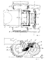
- a hoist 4 Adjacent to the axis 2, a hoist 4 is attached, which usually serves for so-called. Shield support.
- the shield is replaced here by a bracket 4 ', which are stiffened as well as the trailing arm of the hoist 5 with a stable cross brace.
- a pivot arm 4a At the respective console 4 'is ever a pivot arm 4a (see. Fig. 2 ), which carries an additional axle 3 with a clamping connection.
- the additional axis 3 is thus arranged parallel to the axis 2, in particular with the same gauge.
- the additional axis 3 can be identical to the axis 2, but without drive shafts.
- the wheels 3 'on the additional axle 3 may also be formed as twin wheels.
- the hoist 4 here has two hydraulic cylinders 6, preferably with nitrogen storage, which raise or lower the additional axle 3 via the brackets 4 'and the pivot arms 4a (each right and left).
- the raised state is in Fig. 2 shown, with a distance h of the wheels 3 'and the circulating crawler belt 5 (or the rubber band) results for road travel.
- the crawler belt 5 is spared when cornering, since the running pad (here only partially on the wheel 2 'shown) rest essentially only with the footprint of the wheel 2' on the ground.
- Fig. 2 is another hydraulic cylinder as adjusting 7 can be seen, the or preferably protected in the console 4 'is housed and acts on the pivot arm 4a.
- the crawler belt or the endless treadmill 5 can be tensioned.
- the adjusting device 7 can be shortened, so that the chain or the band 5 can be more easily removed from the wheels 2 'and 3'.
- the outer wheel to solve especially if between the Twin wheels 2 'a drive pinion 8 for the positive drive of the crawler belt 5 (or the deceleration or blocking in working position) is provided.
- This pinion is then removed as it may protrude beyond the tire diameter depending on the chain construction.
- the dismantling is completed to a wheel gear relatively quickly.
- the conversion of the wheeled excavator to a semi-crawler vehicle then takes place in reverse order also relatively easy.
Landscapes
- Engineering & Computer Science (AREA)
- Chemical & Material Sciences (AREA)
- Combustion & Propulsion (AREA)
- Transportation (AREA)
- Mechanical Engineering (AREA)
- Mining & Mineral Resources (AREA)
- Civil Engineering (AREA)
- General Engineering & Computer Science (AREA)
- Structural Engineering (AREA)
- Jib Cranes (AREA)
- Road Repair (AREA)
Applications Claiming Priority (1)
| Application Number | Priority Date | Filing Date | Title |
|---|---|---|---|
| DE201020004301 DE202010004301U1 (de) | 2010-03-26 | 2010-03-26 | Selbstfahrende Arbeitsmaschine, insbesondere Radbagger |
Publications (1)
| Publication Number | Publication Date |
|---|---|
| EP2369065A1 true EP2369065A1 (fr) | 2011-09-28 |
Family
ID=43972794
Family Applications (1)
| Application Number | Title | Priority Date | Filing Date |
|---|---|---|---|
| EP11002540A Withdrawn EP2369065A1 (fr) | 2010-03-26 | 2011-03-28 | Machine de travail automobile, notamment excavateur à roues |
Country Status (2)
| Country | Link |
|---|---|
| EP (1) | EP2369065A1 (fr) |
| DE (1) | DE202010004301U1 (fr) |
Cited By (3)
| Publication number | Priority date | Publication date | Assignee | Title |
|---|---|---|---|---|
| DE202016100829U1 (de) | 2016-02-17 | 2016-04-07 | Kuno Moser | Radbagger |
| DE102020100212A1 (de) * | 2020-01-08 | 2021-07-08 | Josef Bergmeister e.K. Bauunternehmen | Kettenlaufwerke für Mobilbagger |
| US11155119B2 (en) | 2013-03-14 | 2021-10-26 | Gregory W. Luker | Traction wheel apparatus with non-uniform tread teeth |
Citations (11)
| Publication number | Priority date | Publication date | Assignee | Title |
|---|---|---|---|---|
| US2433409A (en) * | 1943-06-02 | 1947-12-30 | Walker Brooks | Track and drive from dual tires |
| FR1030204A (fr) * | 1950-12-28 | 1953-06-10 | Système de propulsion à chenilles, notamment pour tracteurs | |
| GB813704A (en) * | 1955-06-15 | 1959-05-21 | Auxiliaire De L Entpr Auxen So | Improvements in or relating to automotive vehicles having a relatively short wheel base |
| DE2166025A1 (de) * | 1970-01-26 | 1972-11-02 | C. van der LeIy N.V., Maasland (Niederlande); | Bodenbearbeitungsmaschine. Ausscheidung aus: 2103278 |
| JPS57202452U (fr) * | 1981-06-16 | 1982-12-23 | ||
| US4635740A (en) * | 1985-01-31 | 1987-01-13 | Krueger David W | Endless track attachment for a wheeled vehicle |
| JPS6448306U (fr) * | 1987-09-22 | 1989-03-24 | ||
| EP1277393A1 (fr) * | 2001-06-27 | 2003-01-22 | CLAAS Selbstfahrende Erntemaschinen GmbH | Agencement de roue porteuse pour une machine agricole |
| DE202007016894U1 (de) | 2006-12-08 | 2008-02-28 | Caterpillar Inc., Peoria | Bagger auf Rädern mit einem Mittel zur Laufverbesserung |
| DE202006017727U1 (de) * | 2006-11-21 | 2008-04-03 | Liebherr-Hydraulikbagger Gmbh | Zweiwegebagger |
| US20090051218A1 (en) * | 2007-08-24 | 2009-02-26 | Crooks Jeffrey J A | Traction Enhancement Device |
Family Cites Families (6)
| Publication number | Priority date | Publication date | Assignee | Title |
|---|---|---|---|---|
| US4727948A (en) * | 1986-08-06 | 1988-03-01 | Julseth Richard A | Rear crawler track retrofit for garden and lawn tractors |
| FR2663269B1 (fr) * | 1990-06-15 | 1995-03-17 | Gilles Poncin | Vehicule leger tous terrains et route a toutes roues motrices. |
| JPH07237567A (ja) * | 1994-02-28 | 1995-09-12 | Honda Motor Co Ltd | クローラベルト式車両の懸架装置 |
| US5975226A (en) * | 1996-07-30 | 1999-11-02 | Honda Giken Kogyo Kabushiki Kaisha | Crawler belt vehicle |
| AU2001236957A1 (en) * | 2000-02-18 | 2001-08-27 | Jlg Industries Inc. | Half-track assembly with suspended idler |
| DE202006019051U1 (de) * | 2006-12-18 | 2008-04-30 | Liebherr-Hydraulikbagger Gmbh | Mobilbagger |
-
2010
- 2010-03-26 DE DE201020004301 patent/DE202010004301U1/de not_active Expired - Lifetime
-
2011
- 2011-03-28 EP EP11002540A patent/EP2369065A1/fr not_active Withdrawn
Patent Citations (11)
| Publication number | Priority date | Publication date | Assignee | Title |
|---|---|---|---|---|
| US2433409A (en) * | 1943-06-02 | 1947-12-30 | Walker Brooks | Track and drive from dual tires |
| FR1030204A (fr) * | 1950-12-28 | 1953-06-10 | Système de propulsion à chenilles, notamment pour tracteurs | |
| GB813704A (en) * | 1955-06-15 | 1959-05-21 | Auxiliaire De L Entpr Auxen So | Improvements in or relating to automotive vehicles having a relatively short wheel base |
| DE2166025A1 (de) * | 1970-01-26 | 1972-11-02 | C. van der LeIy N.V., Maasland (Niederlande); | Bodenbearbeitungsmaschine. Ausscheidung aus: 2103278 |
| JPS57202452U (fr) * | 1981-06-16 | 1982-12-23 | ||
| US4635740A (en) * | 1985-01-31 | 1987-01-13 | Krueger David W | Endless track attachment for a wheeled vehicle |
| JPS6448306U (fr) * | 1987-09-22 | 1989-03-24 | ||
| EP1277393A1 (fr) * | 2001-06-27 | 2003-01-22 | CLAAS Selbstfahrende Erntemaschinen GmbH | Agencement de roue porteuse pour une machine agricole |
| DE202006017727U1 (de) * | 2006-11-21 | 2008-04-03 | Liebherr-Hydraulikbagger Gmbh | Zweiwegebagger |
| DE202007016894U1 (de) | 2006-12-08 | 2008-02-28 | Caterpillar Inc., Peoria | Bagger auf Rädern mit einem Mittel zur Laufverbesserung |
| US20090051218A1 (en) * | 2007-08-24 | 2009-02-26 | Crooks Jeffrey J A | Traction Enhancement Device |
Cited By (5)
| Publication number | Priority date | Publication date | Assignee | Title |
|---|---|---|---|---|
| US11155119B2 (en) | 2013-03-14 | 2021-10-26 | Gregory W. Luker | Traction wheel apparatus with non-uniform tread teeth |
| DE202016100829U1 (de) | 2016-02-17 | 2016-04-07 | Kuno Moser | Radbagger |
| DE202016102019U1 (de) | 2016-02-17 | 2016-07-14 | Kuno Moser | Radbagger |
| DE102017103355A1 (de) | 2016-02-17 | 2017-08-17 | Kuno Moser | Radbagger |
| DE102020100212A1 (de) * | 2020-01-08 | 2021-07-08 | Josef Bergmeister e.K. Bauunternehmen | Kettenlaufwerke für Mobilbagger |
Also Published As
| Publication number | Publication date |
|---|---|
| DE202010004301U1 (de) | 2011-05-05 |
Similar Documents
| Publication | Publication Date | Title |
|---|---|---|
| DE102005013692B4 (de) | Kraftfahrzeug mit Zusatz-Laufkettenfahrwerk | |
| DE4017107C2 (de) | Stetig arbeitendes Gewinnungsgerät für Tagebaue mit einem walzenförmigen Gewinnungsorgan | |
| DE19612559A1 (de) | Mehrzwecke-Baufahrzeug | |
| CH650299A5 (de) | Schreitbagger. | |
| DE212013000022U1 (de) | Anordnung in einer Forstmaschine und mit dementsprechender Anordnung ausgerüstete Forstmaschine | |
| DE2710239A1 (de) | Auf raedern fahrbare baumaschine oder rad-baufahrzeug | |
| DE102014110551A1 (de) | Landwirtschaftliches Fahrzeug | |
| DE2363755C2 (de) | Gleisketten-Fahrzeug mit vier Gleisketteneinheiten | |
| DE102020003044A1 (de) | Baumaschine und verfahren zur erhöhung der standsicherheit einer baumaschine | |
| EP3202985B1 (fr) | Train de roulement flottant, ponton flottant et procede de montage et de demontage de pontons flottants | |
| WO2020025201A1 (fr) | Attelage comprenant un véhicule tracteur et une remorque, véhicule tracteur, remorque et procédé pour la distribution de charge par essieu dans un attelage | |
| DE2140233B2 (de) | Mehrachsiger fahrzeugkran | |
| EP2369065A1 (fr) | Machine de travail automobile, notamment excavateur à roues | |
| DE69624244T2 (de) | Bodenverdichter mit stabilisierendem radsystem | |
| DE2156282B2 (de) | Maschine zum schichtweisen Abtragen von verschlissenen Straßendecken | |
| DE102015220497A1 (de) | Raupenfahrzeug, Verfahren zum Betreiben eines Raupenfahrzeugs | |
| WO2017080667A2 (fr) | Engin de travaux publics, en particulier excavateur mobile | |
| DE102017113910A1 (de) | Raupenfahrwerk | |
| DE4202298C2 (de) | Fahrgestell für Nutzfahrzeug | |
| DD146637A5 (de) | Abtrags-becherwerkslader | |
| EP0663478B1 (fr) | Combinaison d'une excavatrice avec un dispositif vibreur | |
| DE3627719C1 (de) | Bagger,insbesondere selbstfahrender hydraulischer Universal-Kleinbagger | |
| DE3336313C2 (de) | Bodenstützgerät für eine Landmaschine | |
| EP2059639B1 (fr) | Excavateur mobile | |
| DE2009645A1 (de) | Löffelbagger |
Legal Events
| Date | Code | Title | Description |
|---|---|---|---|
| PUAI | Public reference made under article 153(3) epc to a published international application that has entered the european phase |
Free format text: ORIGINAL CODE: 0009012 |
|
| AK | Designated contracting states |
Kind code of ref document: A1 Designated state(s): AL AT BE BG CH CY CZ DE DK EE ES FI FR GB GR HR HU IE IS IT LI LT LU LV MC MK MT NL NO PL PT RO RS SE SI SK SM TR |
|
| AX | Request for extension of the european patent |
Extension state: BA ME |
|
| 17P | Request for examination filed |
Effective date: 20120327 |
|
| STAA | Information on the status of an ep patent application or granted ep patent |
Free format text: STATUS: THE APPLICATION HAS BEEN WITHDRAWN |
|
| 18W | Application withdrawn |
Effective date: 20140204 |