EP2377430A1 - Dispositif d'entrée pour éléments coulissant - Google Patents
Dispositif d'entrée pour éléments coulissant Download PDFInfo
- Publication number
- EP2377430A1 EP2377430A1 EP11173255A EP11173255A EP2377430A1 EP 2377430 A1 EP2377430 A1 EP 2377430A1 EP 11173255 A EP11173255 A EP 11173255A EP 11173255 A EP11173255 A EP 11173255A EP 2377430 A1 EP2377430 A1 EP 2377430A1
- Authority
- EP
- European Patent Office
- Prior art keywords
- coupling element
- stop
- spring
- holder
- feed guide
- Prior art date
- Legal status (The legal status is an assumption and is not a legal conclusion. Google has not performed a legal analysis and makes no representation as to the accuracy of the status listed.)
- Granted
Links
Images


Classifications
-
- E—FIXED CONSTRUCTIONS
- E05—LOCKS; KEYS; WINDOW OR DOOR FITTINGS; SAFES
- E05F—DEVICES FOR MOVING WINGS INTO OPEN OR CLOSED POSITION; CHECKS FOR WINGS; WING FITTINGS NOT OTHERWISE PROVIDED FOR, CONCERNED WITH THE FUNCTIONING OF THE WING
- E05F1/00—Closers or openers for wings, not otherwise provided for in this subclass
- E05F1/08—Closers or openers for wings, not otherwise provided for in this subclass spring-actuated, e.g. for horizontally sliding wings
- E05F1/16—Closers or openers for wings, not otherwise provided for in this subclass spring-actuated, e.g. for horizontally sliding wings for sliding wings
-
- A—HUMAN NECESSITIES
- A47—FURNITURE; DOMESTIC ARTICLES OR APPLIANCES; COFFEE MILLS; SPICE MILLS; SUCTION CLEANERS IN GENERAL
- A47B—TABLES; DESKS; OFFICE FURNITURE; CABINETS; DRAWERS; GENERAL DETAILS OF FURNITURE
- A47B88/00—Drawers for tables, cabinets or like furniture; Guides for drawers
- A47B88/40—Sliding drawers; Slides or guides therefor
- A47B88/453—Actuated drawers
- A47B88/46—Actuated drawers operated by mechanically-stored energy, e.g. by springs
- A47B88/467—Actuated drawers operated by mechanically-stored energy, e.g. by springs self-closing
-
- E—FIXED CONSTRUCTIONS
- E05—LOCKS; KEYS; WINDOW OR DOOR FITTINGS; SAFES
- E05F—DEVICES FOR MOVING WINGS INTO OPEN OR CLOSED POSITION; CHECKS FOR WINGS; WING FITTINGS NOT OTHERWISE PROVIDED FOR, CONCERNED WITH THE FUNCTIONING OF THE WING
- E05F3/00—Closers or openers with braking devices, e.g. checks; Construction of pneumatic or liquid braking devices
- E05F3/04—Closers or openers with braking devices, e.g. checks; Construction of pneumatic or liquid braking devices with liquid piston brakes
-
- E—FIXED CONSTRUCTIONS
- E05—LOCKS; KEYS; WINDOW OR DOOR FITTINGS; SAFES
- E05F—DEVICES FOR MOVING WINGS INTO OPEN OR CLOSED POSITION; CHECKS FOR WINGS; WING FITTINGS NOT OTHERWISE PROVIDED FOR, CONCERNED WITH THE FUNCTIONING OF THE WING
- E05F5/00—Braking devices, e.g. checks; Stops; Buffers
- E05F5/003—Braking devices, e.g. checks; Stops; Buffers for sliding wings
-
- E—FIXED CONSTRUCTIONS
- E05—LOCKS; KEYS; WINDOW OR DOOR FITTINGS; SAFES
- E05Y—INDEXING SCHEME ASSOCIATED WITH SUBCLASSES E05D AND E05F, RELATING TO CONSTRUCTION ELEMENTS, ELECTRIC CONTROL, POWER SUPPLY, POWER SIGNAL OR TRANSMISSION, USER INTERFACES, MOUNTING OR COUPLING, DETAILS, ACCESSORIES, AUXILIARY OPERATIONS NOT OTHERWISE PROVIDED FOR, APPLICATION THEREOF
- E05Y2201/00—Constructional elements; Accessories therefor
- E05Y2201/40—Motors; Magnets; Springs; Weights; Accessories therefor
- E05Y2201/404—Function thereof
- E05Y2201/41—Function thereof for closing
- E05Y2201/412—Function thereof for closing for the final closing movement
-
- E—FIXED CONSTRUCTIONS
- E05—LOCKS; KEYS; WINDOW OR DOOR FITTINGS; SAFES
- E05Y—INDEXING SCHEME ASSOCIATED WITH SUBCLASSES E05D AND E05F, RELATING TO CONSTRUCTION ELEMENTS, ELECTRIC CONTROL, POWER SUPPLY, POWER SIGNAL OR TRANSMISSION, USER INTERFACES, MOUNTING OR COUPLING, DETAILS, ACCESSORIES, AUXILIARY OPERATIONS NOT OTHERWISE PROVIDED FOR, APPLICATION THEREOF
- E05Y2800/00—Details, accessories and auxiliary operations not otherwise provided for
- E05Y2800/20—Combinations of elements
- E05Y2800/21—Combinations of elements of identical elements, e.g. of identical compression springs
-
- E—FIXED CONSTRUCTIONS
- E05—LOCKS; KEYS; WINDOW OR DOOR FITTINGS; SAFES
- E05Y—INDEXING SCHEME ASSOCIATED WITH SUBCLASSES E05D AND E05F, RELATING TO CONSTRUCTION ELEMENTS, ELECTRIC CONTROL, POWER SUPPLY, POWER SIGNAL OR TRANSMISSION, USER INTERFACES, MOUNTING OR COUPLING, DETAILS, ACCESSORIES, AUXILIARY OPERATIONS NOT OTHERWISE PROVIDED FOR, APPLICATION THEREOF
- E05Y2800/00—Details, accessories and auxiliary operations not otherwise provided for
- E05Y2800/20—Combinations of elements
- E05Y2800/23—Combinations of elements of elements of different categories
- E05Y2800/24—Combinations of elements of elements of different categories of springs and brakes
-
- E—FIXED CONSTRUCTIONS
- E05—LOCKS; KEYS; WINDOW OR DOOR FITTINGS; SAFES
- E05Y—INDEXING SCHEME ASSOCIATED WITH SUBCLASSES E05D AND E05F, RELATING TO CONSTRUCTION ELEMENTS, ELECTRIC CONTROL, POWER SUPPLY, POWER SIGNAL OR TRANSMISSION, USER INTERFACES, MOUNTING OR COUPLING, DETAILS, ACCESSORIES, AUXILIARY OPERATIONS NOT OTHERWISE PROVIDED FOR, APPLICATION THEREOF
- E05Y2900/00—Application of doors, windows, wings or fittings thereof
- E05Y2900/20—Application of doors, windows, wings or fittings thereof for furniture, e.g. cabinets
Definitions
- the invention relates to a retraction device, in particular for sliding elements, drawers or sliding doors with damping element and a coupling element, wherein the coupling element between an intake position and an extension position is adjustable, and wherein a tension spring biases the coupling element in the extended position in the direction of the retraction position,
- a damping element is housed in a housing having a damping cylinder in which a piston is adjustable against a damping fluid. To the piston a piston rod is coupled.
- the piston rod is mounted at its free end to a guide carriage.
- This is linearly adjustable in a guide slot of the housing.
- the guide carriage has a bearing lug, which in a bearing receptacle of a coupling member engaging such that between these two parts a pivot bearing is formed.
- the coupling member can thus be pivoted in the extension position relative to the guide carriage in a Abklapp ein. In the Abklapp ein the coupling member is ready to catch a driver, such as a sliding door. The captured driver is then pulled with the coupling member in the retraction position.
- the entire retraction device must be readjusted and, if necessary, dismantled.
- the coupling element carries on a holder a deflectable spring element.
- the coupling element is guided adjustably by means of the bearing pin in the guide slot, and that the pivot axis of the coupling element passes through the bearing pin, then can be easily and space saving the leadership of the coupling element in the guide link realize.
- the bearing pin connects the coupling element with a bearing lug of the piston rod.
- the journal can then be a separate component or molded directly to the coupling element or to the piston rod.
- a possible variant of the invention may be such that the coupling element has a spring holder to which the tension spring is coupled directly at a distance and eccentrically to the pivot axis of the pivot bearing. Characterized in that the point of action of the spring is associated with the coupling element, a tilting moment can be generated. This ensures that the coupling element is reliably pulled in the extended position in the folded position.
- a tilt-stable and secure guidance of the coupling element can be achieved with little effort that the guide slot has two slot guides, which are excluded from two mutually parallel housing walls of the housing, that the coupling element between these two housing walls and is guided with one bearing pin in the slot guides ,
- a possible variant of the invention may be such that the coupling element carries at least one guide element, which is guided in the guide slot and pivots in the folded-down extension position in a receptacle of the guide slot.
- the coupling element has a first and a second stop, which are arranged spaced from each other, that the second stop is supported by a spring element, and that the spring element is deflectable in a, substantially in the pivoting direction of the coupling element extending adjustment, then
- the feeder can be used on both sides of the sliding element to be used optionally.
- the spring element then always deviates in the direction of the housing interior.
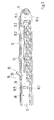
- the Figures 1 and 2 show a feeder 10 with a housing 12 which is provided at its longitudinal ends with fastening lugs 11.
- the attachment lugs 11 have screw receptacles.
- the housing 12 has two mutually parallel housing walls 12.3, each extending between the attachment lugs 11. From the mounting walls 12.4 guide slots 12.2 are excluded in the form of slot guides.
- the two guide slots 12.2 are congruent. They have a linear guide section, which merges into a widened receptacle 12.3.
- a coupling element 20 is adjustably housed.
- the design of the executed as an injection molded coupling element 20 is closer from the FIGS. 4 and 5 out.
- the coupling element 20 has a base part 21.1, to which a holder 21 is formed in the form of a cantilever.
- the holder 21 carries a leaf spring-like spring element 23.
- the spring element 23 has at its free end a second stop 24 with a stop surface 24.1.
- the second stop 24 terminates with a locking projection 24.2 issued in the direction of the holder 21.
- the second stop 24 abuts a recessed guide surface 26 of the holder 21, as the FIG. 6 more clearly shows.
- undercut surfaces are provided on the second paragraph 24 and the holder 21, which lie adjacent to each other form a guide 24.3. This guide 24.3 prevents deflection of the second stop 24 perpendicular to the guide surface.
- the FIG. 4 shows the spring element 23 in the deflected, the FIG. 5 in the deflected position.
- the base part 21.1 also carries a first stop 25 which projects in the same direction as the second stop 24. As the FIG. 5 shows, the two stops 24, 25 to each other at a distance, so that they define a receiving space between them.
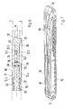
- a damping element can be coupled directly pivotally.
- the damping element has a damping cylinder 30, in which a piston can be displaced against the pressure of a damping fluid (for example, gaseous or liquid).
- the piston carries a piston rod 32, which is led out of the damping cylinder.
- the piston rod 32 has a bearing lug 33 at its free end. This is pivotally held on a bearing receptacle 28 of the coupling element 20.
- the FIG. 6 shows an example of the connection between the piston rod 32 and coupling element 20. Accordingly, the bearing lug 33 and the bearing receptacle 28 mutually aligned bores through which a designed as a separate component bearing pin 29 is guided in the form of a cylindrical pin. The bearing pin 29 is frictionally held either in the bearing lug 33 or in the bearing receptacle 28. The result is the pivot bearing whose pivot axis extends through the central longitudinal axis of the bearing pin 29.
- a further variant of the invention, not shown in the drawings, may be such that the piston rod 32 and the coupling element 20 have molded-on components which engage in one another to form the pivot bearing.
- a bearing pin 29 may be formed on the coupling element 20 (or the piston rod 32) and the piston rod 32 (or the coupling element 20) may be pushed onto this bearing journal 29 with a bore. Then can be dispensed with the bearing pin 29 as a separate component.
- the bearing pin 29 protrudes on both sides via the coupling element 20, wherein the projecting portions engage in the guide slots 12.2.
- the coupling element 20 is guided stably between the two housing walls 12.4 and in the guide slots 12.2.
- a spring holder 27 is disposed below the pivot bearing. This fixes the end of a tension spring 35, which is fixed at its other end to the housing 12. With the spaced arrangement of the connection point of the tension spring 35 can be a clockwise (in accordance with FIG. 5 ) are applied to the pivot axis of the pivot bearing torque acting.
- FIGS. 1 to 3 show is in the FIGS. 4 and 5 shown arrangement housed in the housing 12.
- the damping cylinder 30 is inserted into a groove-shaped receiving compartment of the housing 12.
- the damping cylinder 30 is fixed by means of protruding from the housing walls 12.5 projections 12.5, which engage in an introduced into the damping cylinder 30 circumferential groove 31.
- the FIG. 1 shows the coupling element 20 in its initial position.
- the coupling element 20 is folded in the pivot bearing relative to the piston rod 32, that on both sides of the holders 21 of the coupling element 20 integrally formed guide elements 22 are held in the two receptacles 12.3 of the guide slots 12.2.
- the tension spring 35 is in this position in its clamping position and brings bias on the coupling element 20 such that it is held in the folded position.
- the coupling element 20 is ready in the position shown with a driver 40 into engagement.
- the driver 40 may be stationary, for example, on a furniture carcass a sliding door door frame and the retraction device to be attached to the sliding part to be moved (drawer, sliding door, etc.) (or vice versa).
- the impact of the driver 40 on the first stop 25 is cushioned by the damping element (damping cylinder 30). And thus the sliding part is pulled by means of the force of the tension spring 35 in its closed position.
- the coupling element 20 is pulled by the voltage applied to the second stop 24 driver 25 and in the in FIG. 1 shown position spent.
- the tension spring 35 is tensioned again and the piston rod 32 is pulled out.
- the sliding part is then out of engagement with the retraction device and can be moved further into the open position. Now it may happen that due to, for example, a malfunction, the coupling element 20 in the in FIG. 2 shown position, but the driver 40 is outside the area formed between the stops 24, 25 and before the second stop 24.
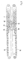
- FIG. 7 shows an arrangement as it can be found in heavy sliding parts (for example, large sliding doors) use.
- FIG. 8 Another parallel arrangement is in the FIG. 8 shown. As this illustration shows, the collection devices are arranged opposite one another, the housing walls 12.4 lying in pairs in one plane.
- the stops 24, 25 overlap. Like the FIG. 6 shows, the collection devices on two mutually parallel mounting planes E, with which they can be applied to fastening surfaces and fixed thereto. Centered between the mounting planes E and parallel to these is the median transverse plane M of the feeder. As the FIG. 6 let the stops 24, 25 do not project beyond this central transverse plane M, so that the in FIG. 8 shown overlapped position of the stops 24, 25 is possible.
Landscapes
- Engineering & Computer Science (AREA)
- Mechanical Engineering (AREA)
- Closing And Opening Devices For Wings, And Checks For Wings (AREA)
- Drawers Of Furniture (AREA)
- Springs (AREA)
- Fluid-Damping Devices (AREA)
Priority Applications (1)
| Application Number | Priority Date | Filing Date | Title |
|---|---|---|---|
| EP20150642.5A EP3666119A1 (fr) | 2007-02-20 | 2008-01-25 | Dispositif d'escamotage pour éléments coulissants |
Applications Claiming Priority (3)
| Application Number | Priority Date | Filing Date | Title |
|---|---|---|---|
| DE102007008688A DE102007008688A1 (de) | 2007-02-20 | 2007-02-20 | Einzugvorrichtung für Schiebelemente |
| PCT/EP2008/000570 WO2008101582A2 (fr) | 2007-02-20 | 2008-01-25 | Dispositif d'escamotage pour éléments coulissants |
| EP08707280.7A EP2120644B2 (fr) | 2007-02-20 | 2008-01-25 | Dispositif d'escamotage pour éléments coulissants |
Related Parent Applications (3)
| Application Number | Title | Priority Date | Filing Date |
|---|---|---|---|
| EP08707280.7A Division-Into EP2120644B2 (fr) | 2007-02-20 | 2008-01-25 | Dispositif d'escamotage pour éléments coulissants |
| EP08707280.7A Division EP2120644B2 (fr) | 2007-02-20 | 2008-01-25 | Dispositif d'escamotage pour éléments coulissants |
| EP08707280.7 Division | 2008-01-25 |
Related Child Applications (2)
| Application Number | Title | Priority Date | Filing Date |
|---|---|---|---|
| EP20150642.5A Division-Into EP3666119A1 (fr) | 2007-02-20 | 2008-01-25 | Dispositif d'escamotage pour éléments coulissants |
| EP20150642.5A Division EP3666119A1 (fr) | 2007-02-20 | 2008-01-25 | Dispositif d'escamotage pour éléments coulissants |
Publications (2)
| Publication Number | Publication Date |
|---|---|
| EP2377430A1 true EP2377430A1 (fr) | 2011-10-19 |
| EP2377430B1 EP2377430B1 (fr) | 2020-06-17 |
Family
ID=39474044
Family Applications (3)
| Application Number | Title | Priority Date | Filing Date |
|---|---|---|---|
| EP08707280.7A Not-in-force EP2120644B2 (fr) | 2007-02-20 | 2008-01-25 | Dispositif d'escamotage pour éléments coulissants |
| EP20150642.5A Withdrawn EP3666119A1 (fr) | 2007-02-20 | 2008-01-25 | Dispositif d'escamotage pour éléments coulissants |
| EP11173255.8A Active EP2377430B1 (fr) | 2007-02-20 | 2008-01-25 | Dispositif d'entrée pour éléments coulissant |
Family Applications Before (2)
| Application Number | Title | Priority Date | Filing Date |
|---|---|---|---|
| EP08707280.7A Not-in-force EP2120644B2 (fr) | 2007-02-20 | 2008-01-25 | Dispositif d'escamotage pour éléments coulissants |
| EP20150642.5A Withdrawn EP3666119A1 (fr) | 2007-02-20 | 2008-01-25 | Dispositif d'escamotage pour éléments coulissants |
Country Status (7)
| Country | Link |
|---|---|
| EP (3) | EP2120644B2 (fr) |
| JP (1) | JP5096499B2 (fr) |
| CZ (2) | CZ24790U1 (fr) |
| DE (3) | DE102007008688A1 (fr) |
| ES (2) | ES2639851T5 (fr) |
| PL (1) | PL2120644T5 (fr) |
| WO (1) | WO2008101582A2 (fr) |
Families Citing this family (21)
| Publication number | Priority date | Publication date | Assignee | Title |
|---|---|---|---|---|
| DE102008051360A1 (de) | 2008-10-15 | 2010-05-12 | Karl Simon Gmbh & Co. Kg | Einzugsvorrichtung |
| DE202008016409U1 (de) | 2008-12-13 | 2010-04-22 | Paul Hettich Gmbh & Co. Kg | Selbsteinzugsvorrichtung und Auszugsführung |
| DE102009016427B4 (de) * | 2009-04-04 | 2020-02-06 | Karl Simon Gmbh & Co. Kg | Verfahren zum Bedienen einer Schublade |
| DE102009021202B4 (de) | 2009-04-04 | 2014-09-25 | Karl Simon Gmbh & Co. Kg | Einzugvorrichtung |
| WO2010112593A1 (fr) * | 2009-04-04 | 2010-10-07 | Karl Simon Gmbh & Co. Kg | Dispositif d'escamotage |
| DE102009020994B4 (de) * | 2009-05-12 | 2017-08-10 | Karl Simon Gmbh & Co. Kg | Einzugvorrichtung |
| DE202009006855U1 (de) | 2009-05-12 | 2010-09-30 | Karl Simon Gmbh & Co. Kg | Einzugvorrichtung |
| DE202009014685U1 (de) | 2009-10-14 | 2010-06-17 | Karl Simon Gmbh & Co. Kg | Schiebeanordnung |
| IT1397672B1 (it) * | 2010-01-22 | 2013-01-18 | Eclisse Srl | Porta scorrevole a scomparsa, con dispositivi di controllo della corsa e di autochiusura del pannello porta. |
| DE202010008079U1 (de) | 2010-07-14 | 2010-09-09 | Anton Schneider Gmbh & Co Kg | Ausziehführung für Schubladen |
| DE102010043422B4 (de) | 2010-11-04 | 2024-04-04 | Schock Metallwerk Gmbh | Befestigungsvorrichtung |
| DE102011050621A1 (de) | 2011-05-24 | 2012-11-29 | Karl Simon Gmbh & Co. Kg | Einzugvorrichtung |
| ES2474290B1 (es) * | 2013-01-08 | 2015-01-02 | Industrias Auxiliares, S.A. (Indaux) | Dispositivo de autocierre para partes móviles correderas |
| DE102013104886A1 (de) | 2013-05-13 | 2014-11-13 | Karl Simon Gmbh & Co. Kg | Schiebeanordnung |
| DE102015003414B3 (de) | 2015-03-17 | 2016-06-16 | Günther Zimmer | Kombinierte Beschleunigungs- und Verzögerungsvorrichtung mit Überlastschutz |
| CN105534092A (zh) * | 2016-01-21 | 2016-05-04 | 泛亚电子工业(无锡)有限公司 | 抽屉用滑轨自锁阻尼机构 |
| DE102016107919A1 (de) * | 2016-04-28 | 2017-11-02 | Paul Hettich Gmbh & Co. Kg | Ausstoßvorrichtung für ein bewegbares Möbelteil, Möbelteil und Verfahren zum Öffnen und Schließen eines bewegbaren Möbelteils |
| CN106121431B (zh) * | 2016-08-30 | 2017-08-25 | 中山市佰迪克五金制品有限公司 | 一种门的组合缓冲系统 |
| DE102018008207B4 (de) * | 2018-10-14 | 2023-11-09 | Günther Zimmer | Verzögerungsvorrichtung mit mehrteiligem Mitnahmeelement |
| AT523429B1 (de) * | 2020-06-10 | 2021-08-15 | Fulterer Ag & Co Kg | Selbsteinziehvorrichtung |
| CN112116848B (zh) * | 2020-07-20 | 2023-01-31 | 浙江科技学院 | 一种大学生创新创业教育教学设备 |
Citations (3)
| Publication number | Priority date | Publication date | Assignee | Title |
|---|---|---|---|---|
| WO2005055767A1 (fr) * | 2003-12-05 | 2005-06-23 | Titus International Plc | Ameliorations apportees a des commandes de deplacement |
| WO2006050510A2 (fr) * | 2004-11-05 | 2006-05-11 | Accuride International, Inc. | Mecanisme de mouvement amorti et coulisseau integrant ce dernier |
| EP1658785A1 (fr) | 2004-11-23 | 2006-05-24 | Vauth-Sagel Holding GmbH & Co. KG | Aide de fermeture pour un tiroir |
Family Cites Families (15)
| Publication number | Priority date | Publication date | Assignee | Title |
|---|---|---|---|---|
| AT401716B (de) † | 1990-12-14 | 1996-11-25 | Blum Gmbh Julius | Schublade mit schliessvorrichtungen |
| DE9007365U1 (de) * | 1990-06-26 | 1991-07-11 | Karl Lautenschläger GmbH & Co KG Möbelbeschlagfabrik, 6107 Reinheim | Einzugsautomatik für Schubladen-Ausziehführungen |
| DE9013161U1 (de) † | 1990-09-17 | 1990-11-22 | Paul Hettich GmbH & Co, 4983 Kirchlengern | Vorrichtung zum Halten eines in einen Möbelkorpus eingeschobenen Schubkastens |
| DE9420920U1 (de) † | 1994-12-30 | 1995-02-09 | Klaus Brummernhenrich Kunststoffverarbeitung, Werkzeugbau, Spritzgießerei, 32108 Bad Salzuflen | Schubkasten-Einziehbeschlag |
| TW564720U (en) † | 2002-06-20 | 2003-12-01 | Nan Juen Int Co Ltd | Buffering and returning device for drawer rail |
| DE202004005322U1 (de) † | 2003-11-05 | 2005-03-24 | Alfit Ag Goetzis | Einzugsautomatik für Schubladen-Ausziehführungen |
| DE20308217U1 (de) * | 2003-05-22 | 2003-07-31 | Hettich-Heinze GmbH & Co. KG, 32139 Spenge | Dämpfungs- und Einzugsvorrichtung |
| DE20311795U1 (de) * | 2003-07-31 | 2004-11-18 | Alfit Ag | Schubladen-Ausziehführung mit Einzugsautomatik mit integrierter Dämpfung |
| JP4436154B2 (ja) † | 2004-02-23 | 2010-03-24 | 不二ラテックス株式会社 | 抽斗案内具及びショックアブソーバ |
| DE202004006410U1 (de) * | 2004-04-20 | 2005-09-01 | Alfit Ag | Einzugsautomatik mit Dämpfungsvorrichtung für Schubladen-Ausziehführungen |
| DE202005004336U1 (de) † | 2005-03-17 | 2005-06-23 | Hettich-Heinze Gmbh & Co. Kg | Selbsteinzugsvorrichtung für bewegliche Möbelteile |
| JP4675145B2 (ja) † | 2005-05-02 | 2011-04-20 | 株式会社ニフコ | 緩衝装置および引出装置 |
| DE202005014050U1 (de) † | 2005-07-15 | 2007-01-04 | Alfit Ag | Verschiebungsautomatik für Möbelauszüge, insbesondere Schubladen |
| DE202005015529U1 (de) † | 2005-10-04 | 2007-02-15 | Paul Hettich Gmbh & Co. Kg | Einzugsvorrichtung |
| DE102006058639B4 (de) * | 2006-12-11 | 2008-08-14 | Zimmer, Günther | Kombinierte Verzögerungs- und Beschleunigungsvorrichtung |
-
2007
- 2007-02-20 DE DE102007008688A patent/DE102007008688A1/de not_active Ceased
- 2007-02-20 DE DE202007019190U patent/DE202007019190U1/de not_active Expired - Lifetime
-
2008
- 2008-01-25 CZ CZ201125011U patent/CZ24790U1/cs not_active IP Right Cessation
- 2008-01-25 DE DE202008018154U patent/DE202008018154U1/de not_active Expired - Lifetime
- 2008-01-25 EP EP08707280.7A patent/EP2120644B2/fr not_active Not-in-force
- 2008-01-25 EP EP20150642.5A patent/EP3666119A1/fr not_active Withdrawn
- 2008-01-25 JP JP2009549788A patent/JP5096499B2/ja not_active Expired - Fee Related
- 2008-01-25 WO PCT/EP2008/000570 patent/WO2008101582A2/fr not_active Ceased
- 2008-01-25 ES ES08707280T patent/ES2639851T5/es active Active
- 2008-01-25 EP EP11173255.8A patent/EP2377430B1/fr active Active
- 2008-01-25 ES ES11173255T patent/ES2815929T3/es active Active
- 2008-01-25 PL PL08707280T patent/PL2120644T5/pl unknown
- 2008-01-25 CZ CZ201125012U patent/CZ24243U1/cs not_active IP Right Cessation
Patent Citations (3)
| Publication number | Priority date | Publication date | Assignee | Title |
|---|---|---|---|---|
| WO2005055767A1 (fr) * | 2003-12-05 | 2005-06-23 | Titus International Plc | Ameliorations apportees a des commandes de deplacement |
| WO2006050510A2 (fr) * | 2004-11-05 | 2006-05-11 | Accuride International, Inc. | Mecanisme de mouvement amorti et coulisseau integrant ce dernier |
| EP1658785A1 (fr) | 2004-11-23 | 2006-05-24 | Vauth-Sagel Holding GmbH & Co. KG | Aide de fermeture pour un tiroir |
Also Published As
| Publication number | Publication date |
|---|---|
| CZ24243U1 (cs) | 2012-09-03 |
| ES2639851T3 (es) | 2017-10-30 |
| PL2120644T5 (pl) | 2020-11-16 |
| EP2120644B2 (fr) | 2020-06-10 |
| JP5096499B2 (ja) | 2012-12-12 |
| WO2008101582A2 (fr) | 2008-08-28 |
| CZ24790U1 (cs) | 2013-01-10 |
| WO2008101582A3 (fr) | 2008-11-20 |
| EP2120644A2 (fr) | 2009-11-25 |
| DE202008018154U1 (de) | 2011-12-08 |
| ES2815929T3 (es) | 2021-03-31 |
| EP2377430B1 (fr) | 2020-06-17 |
| JP2010519434A (ja) | 2010-06-03 |
| DE202007019190U1 (de) | 2011-02-10 |
| EP2120644B1 (fr) | 2017-06-21 |
| ES2639851T5 (es) | 2021-03-29 |
| EP3666119A1 (fr) | 2020-06-17 |
| PL2120644T3 (pl) | 2017-12-29 |
| DE102007008688A1 (de) | 2008-08-21 |
Similar Documents
| Publication | Publication Date | Title |
|---|---|---|
| EP2120644B1 (fr) | Dispositif d'escamotage pour éléments coulissants | |
| EP2445376B1 (fr) | Dispositif de retour automatique et guidage télescopique | |
| EP2353445B1 (fr) | Glissière pour retracter des parties de meubles | |
| EP3973126A1 (fr) | Ferrure de meuble | |
| DE102017113862B3 (de) | Endlagedämpfungsvorrichtung und Anordnung mit einer Endlagedämpfungsvorrichtung | |
| WO2020236100A1 (fr) | Ferrure pour meuble | |
| EP3289155A1 (fr) | Dispositif d'éjection pour un élément mobile de meuble | |
| EP2526825B1 (fr) | Dispositif de rétraction | |
| EP1482183B1 (fr) | dispositif pour recevoir un insert verrouillable et détachable | |
| DE102009020994B4 (de) | Einzugvorrichtung | |
| EP3142516B1 (fr) | Dispositif de rétraction destiné à un meuble | |
| DE202011051957U1 (de) | Türfeststeller für Kraftfahrzeuge | |
| EP2694765A1 (fr) | Dispositif de rentrée | |
| CH712730A1 (de) | Kopplungsmechanismus mit einem zwangsgeführten Kopplungselement für ein mechatronisches Schliesssystem. | |
| EP3166444A1 (fr) | Guidage télescopique pour une partie de meuble mobile | |
| DE102015120559B3 (de) | Montageelement zur Befestigung von Türbändern | |
| EP2848759B1 (fr) | Dispositif d'amortissement | |
| DE102021108249A1 (de) | Koppelelement, Schließsystem und Möbel | |
| EP1001120B1 (fr) | Fermeture | |
| DE202009006855U1 (de) | Einzugvorrichtung | |
| EP3563724A1 (fr) | Dispositif de fermeture d'une partie de meuble mobile | |
| WO2012139697A1 (fr) | Système de fermeture de porte | |
| EP4538491A1 (fr) | Dispositif de mouvement | |
| EP2845978A1 (fr) | Actionneur de porte | |
| DE102024117706A1 (de) | Scharnier |
Legal Events
| Date | Code | Title | Description |
|---|---|---|---|
| AC | Divisional application: reference to earlier application |
Ref document number: 2120644 Country of ref document: EP Kind code of ref document: P |
|
| AK | Designated contracting states |
Kind code of ref document: A1 Designated state(s): AT BE BG CH CY CZ DE DK EE ES FI FR GB GR HR HU IE IS IT LI LT LU LV MC MT NL NO PL PT RO SE SI SK TR |
|
| PUAI | Public reference made under article 153(3) epc to a published international application that has entered the european phase |
Free format text: ORIGINAL CODE: 0009012 |
|
| 17P | Request for examination filed |
Effective date: 20120419 |
|
| 17Q | First examination report despatched |
Effective date: 20120710 |
|
| STAA | Information on the status of an ep patent application or granted ep patent |
Free format text: STATUS: EXAMINATION IS IN PROGRESS |
|
| REG | Reference to a national code |
Ref country code: DE Ref legal event code: R079 Ref document number: 502008017099 Country of ref document: DE Free format text: PREVIOUS MAIN CLASS: A47B0088040000 Ipc: A47B0088467000 |
|
| GRAP | Despatch of communication of intention to grant a patent |
Free format text: ORIGINAL CODE: EPIDOSNIGR1 |
|
| STAA | Information on the status of an ep patent application or granted ep patent |
Free format text: STATUS: GRANT OF PATENT IS INTENDED |
|
| RIC1 | Information provided on ipc code assigned before grant |
Ipc: A47B 88/467 20170101AFI20200107BHEP |
|
| INTG | Intention to grant announced |
Effective date: 20200131 |
|
| GRAS | Grant fee paid |
Free format text: ORIGINAL CODE: EPIDOSNIGR3 |
|
| GRAA | (expected) grant |
Free format text: ORIGINAL CODE: 0009210 |
|
| STAA | Information on the status of an ep patent application or granted ep patent |
Free format text: STATUS: THE PATENT HAS BEEN GRANTED |
|
| AC | Divisional application: reference to earlier application |
Ref document number: 2120644 Country of ref document: EP Kind code of ref document: P |
|
| AK | Designated contracting states |
Kind code of ref document: B1 Designated state(s): AT BE BG CH CY CZ DE DK EE ES FI FR GB GR HR HU IE IS IT LI LT LU LV MC MT NL NO PL PT RO SE SI SK TR |
|
| REG | Reference to a national code |
Ref country code: GB Ref legal event code: FG4D Free format text: NOT ENGLISH |
|
| REG | Reference to a national code |
Ref country code: CH Ref legal event code: EP |
|
| REG | Reference to a national code |
Ref country code: IE Ref legal event code: FG4D Free format text: LANGUAGE OF EP DOCUMENT: GERMAN |
|
| REG | Reference to a national code |
Ref country code: DE Ref legal event code: R096 Ref document number: 502008017099 Country of ref document: DE |
|
| REG | Reference to a national code |
Ref country code: AT Ref legal event code: REF Ref document number: 1280304 Country of ref document: AT Kind code of ref document: T Effective date: 20200715 |
|
| REG | Reference to a national code |
Ref country code: DE Ref legal event code: R081 Ref document number: 502008017099 Country of ref document: DE Owner name: TITUS D.O.O. DEKANI, SI Free format text: FORMER OWNER: KARL SIMON GMBH & CO. KG, 78733 AICHHALDEN, DE |
|
| RAP2 | Party data changed (patent owner data changed or rights of a patent transferred) |
Owner name: TITUS D.O.O. DEKANI |
|
| PG25 | Lapsed in a contracting state [announced via postgrant information from national office to epo] |
Ref country code: LT Free format text: LAPSE BECAUSE OF FAILURE TO SUBMIT A TRANSLATION OF THE DESCRIPTION OR TO PAY THE FEE WITHIN THE PRESCRIBED TIME-LIMIT Effective date: 20200617 Ref country code: SE Free format text: LAPSE BECAUSE OF FAILURE TO SUBMIT A TRANSLATION OF THE DESCRIPTION OR TO PAY THE FEE WITHIN THE PRESCRIBED TIME-LIMIT Effective date: 20200617 Ref country code: FI Free format text: LAPSE BECAUSE OF FAILURE TO SUBMIT A TRANSLATION OF THE DESCRIPTION OR TO PAY THE FEE WITHIN THE PRESCRIBED TIME-LIMIT Effective date: 20200617 Ref country code: GR Free format text: LAPSE BECAUSE OF FAILURE TO SUBMIT A TRANSLATION OF THE DESCRIPTION OR TO PAY THE FEE WITHIN THE PRESCRIBED TIME-LIMIT Effective date: 20200918 Ref country code: NO Free format text: LAPSE BECAUSE OF FAILURE TO SUBMIT A TRANSLATION OF THE DESCRIPTION OR TO PAY THE FEE WITHIN THE PRESCRIBED TIME-LIMIT Effective date: 20200917 |
|
| REG | Reference to a national code |
Ref country code: LT Ref legal event code: MG4D |
|
| REG | Reference to a national code |
Ref country code: NL Ref legal event code: MP Effective date: 20200617 |
|
| PG25 | Lapsed in a contracting state [announced via postgrant information from national office to epo] |
Ref country code: HR Free format text: LAPSE BECAUSE OF FAILURE TO SUBMIT A TRANSLATION OF THE DESCRIPTION OR TO PAY THE FEE WITHIN THE PRESCRIBED TIME-LIMIT Effective date: 20200617 Ref country code: LV Free format text: LAPSE BECAUSE OF FAILURE TO SUBMIT A TRANSLATION OF THE DESCRIPTION OR TO PAY THE FEE WITHIN THE PRESCRIBED TIME-LIMIT Effective date: 20200617 Ref country code: BG Free format text: LAPSE BECAUSE OF FAILURE TO SUBMIT A TRANSLATION OF THE DESCRIPTION OR TO PAY THE FEE WITHIN THE PRESCRIBED TIME-LIMIT Effective date: 20200917 |
|
| PG25 | Lapsed in a contracting state [announced via postgrant information from national office to epo] |
Ref country code: NL Free format text: LAPSE BECAUSE OF FAILURE TO SUBMIT A TRANSLATION OF THE DESCRIPTION OR TO PAY THE FEE WITHIN THE PRESCRIBED TIME-LIMIT Effective date: 20200617 |
|
| PG25 | Lapsed in a contracting state [announced via postgrant information from national office to epo] |
Ref country code: PT Free format text: LAPSE BECAUSE OF FAILURE TO SUBMIT A TRANSLATION OF THE DESCRIPTION OR TO PAY THE FEE WITHIN THE PRESCRIBED TIME-LIMIT Effective date: 20201019 Ref country code: CZ Free format text: LAPSE BECAUSE OF FAILURE TO SUBMIT A TRANSLATION OF THE DESCRIPTION OR TO PAY THE FEE WITHIN THE PRESCRIBED TIME-LIMIT Effective date: 20200617 Ref country code: RO Free format text: LAPSE BECAUSE OF FAILURE TO SUBMIT A TRANSLATION OF THE DESCRIPTION OR TO PAY THE FEE WITHIN THE PRESCRIBED TIME-LIMIT Effective date: 20200617 Ref country code: EE Free format text: LAPSE BECAUSE OF FAILURE TO SUBMIT A TRANSLATION OF THE DESCRIPTION OR TO PAY THE FEE WITHIN THE PRESCRIBED TIME-LIMIT Effective date: 20200617 |
|
| PG25 | Lapsed in a contracting state [announced via postgrant information from national office to epo] |
Ref country code: IS Free format text: LAPSE BECAUSE OF FAILURE TO SUBMIT A TRANSLATION OF THE DESCRIPTION OR TO PAY THE FEE WITHIN THE PRESCRIBED TIME-LIMIT Effective date: 20201017 Ref country code: SK Free format text: LAPSE BECAUSE OF FAILURE TO SUBMIT A TRANSLATION OF THE DESCRIPTION OR TO PAY THE FEE WITHIN THE PRESCRIBED TIME-LIMIT Effective date: 20200617 Ref country code: PL Free format text: LAPSE BECAUSE OF FAILURE TO SUBMIT A TRANSLATION OF THE DESCRIPTION OR TO PAY THE FEE WITHIN THE PRESCRIBED TIME-LIMIT Effective date: 20200617 |
|
| REG | Reference to a national code |
Ref country code: DE Ref legal event code: R097 Ref document number: 502008017099 Country of ref document: DE |
|
| REG | Reference to a national code |
Ref country code: ES Ref legal event code: FG2A Ref document number: 2815929 Country of ref document: ES Kind code of ref document: T3 Effective date: 20210331 |
|
| PLBE | No opposition filed within time limit |
Free format text: ORIGINAL CODE: 0009261 |
|
| STAA | Information on the status of an ep patent application or granted ep patent |
Free format text: STATUS: NO OPPOSITION FILED WITHIN TIME LIMIT |
|
| PG25 | Lapsed in a contracting state [announced via postgrant information from national office to epo] |
Ref country code: DK Free format text: LAPSE BECAUSE OF FAILURE TO SUBMIT A TRANSLATION OF THE DESCRIPTION OR TO PAY THE FEE WITHIN THE PRESCRIBED TIME-LIMIT Effective date: 20200617 |
|
| 26N | No opposition filed |
Effective date: 20210318 |
|
| PG25 | Lapsed in a contracting state [announced via postgrant information from national office to epo] |
Ref country code: SI Free format text: LAPSE BECAUSE OF FAILURE TO SUBMIT A TRANSLATION OF THE DESCRIPTION OR TO PAY THE FEE WITHIN THE PRESCRIBED TIME-LIMIT Effective date: 20200617 |
|
| PG25 | Lapsed in a contracting state [announced via postgrant information from national office to epo] |
Ref country code: MC Free format text: LAPSE BECAUSE OF FAILURE TO SUBMIT A TRANSLATION OF THE DESCRIPTION OR TO PAY THE FEE WITHIN THE PRESCRIBED TIME-LIMIT Effective date: 20200617 |
|
| REG | Reference to a national code |
Ref country code: CH Ref legal event code: PL |
|
| GBPC | Gb: european patent ceased through non-payment of renewal fee |
Effective date: 20210125 |
|
| PG25 | Lapsed in a contracting state [announced via postgrant information from national office to epo] |
Ref country code: LU Free format text: LAPSE BECAUSE OF NON-PAYMENT OF DUE FEES Effective date: 20210125 |
|
| REG | Reference to a national code |
Ref country code: BE Ref legal event code: MM Effective date: 20210131 |
|
| PG25 | Lapsed in a contracting state [announced via postgrant information from national office to epo] |
Ref country code: FR Free format text: LAPSE BECAUSE OF NON-PAYMENT OF DUE FEES Effective date: 20210131 |
|
| PG25 | Lapsed in a contracting state [announced via postgrant information from national office to epo] |
Ref country code: LI Free format text: LAPSE BECAUSE OF NON-PAYMENT OF DUE FEES Effective date: 20210131 Ref country code: CH Free format text: LAPSE BECAUSE OF NON-PAYMENT OF DUE FEES Effective date: 20210131 Ref country code: GB Free format text: LAPSE BECAUSE OF NON-PAYMENT OF DUE FEES Effective date: 20210125 |
|
| PG25 | Lapsed in a contracting state [announced via postgrant information from national office to epo] |
Ref country code: IE Free format text: LAPSE BECAUSE OF NON-PAYMENT OF DUE FEES Effective date: 20210125 |
|
| REG | Reference to a national code |
Ref country code: AT Ref legal event code: MM01 Ref document number: 1280304 Country of ref document: AT Kind code of ref document: T Effective date: 20210125 |
|
| REG | Reference to a national code |
Ref country code: ES Ref legal event code: FD2A Effective date: 20220427 |
|
| PG25 | Lapsed in a contracting state [announced via postgrant information from national office to epo] |
Ref country code: AT Free format text: LAPSE BECAUSE OF NON-PAYMENT OF DUE FEES Effective date: 20210125 |
|
| PG25 | Lapsed in a contracting state [announced via postgrant information from national office to epo] |
Ref country code: IS Free format text: LAPSE BECAUSE OF FAILURE TO SUBMIT A TRANSLATION OF THE DESCRIPTION OR TO PAY THE FEE WITHIN THE PRESCRIBED TIME-LIMIT Effective date: 20201017 |
|
| PG25 | Lapsed in a contracting state [announced via postgrant information from national office to epo] |
Ref country code: ES Free format text: LAPSE BECAUSE OF NON-PAYMENT OF DUE FEES Effective date: 20210126 Ref country code: BE Free format text: LAPSE BECAUSE OF NON-PAYMENT OF DUE FEES Effective date: 20210131 |
|
| PG25 | Lapsed in a contracting state [announced via postgrant information from national office to epo] |
Ref country code: HU Free format text: LAPSE BECAUSE OF FAILURE TO SUBMIT A TRANSLATION OF THE DESCRIPTION OR TO PAY THE FEE WITHIN THE PRESCRIBED TIME-LIMIT; INVALID AB INITIO Effective date: 20080125 Ref country code: CY Free format text: LAPSE BECAUSE OF FAILURE TO SUBMIT A TRANSLATION OF THE DESCRIPTION OR TO PAY THE FEE WITHIN THE PRESCRIBED TIME-LIMIT Effective date: 20200617 |
|
| P01 | Opt-out of the competence of the unified patent court (upc) registered |
Effective date: 20230517 |
|
| PG25 | Lapsed in a contracting state [announced via postgrant information from national office to epo] |
Ref country code: MT Free format text: LAPSE BECAUSE OF FAILURE TO SUBMIT A TRANSLATION OF THE DESCRIPTION OR TO PAY THE FEE WITHIN THE PRESCRIBED TIME-LIMIT Effective date: 20200617 |
|
| PGFP | Annual fee paid to national office [announced via postgrant information from national office to epo] |
Ref country code: DE Payment date: 20260121 Year of fee payment: 19 |
|
| PGFP | Annual fee paid to national office [announced via postgrant information from national office to epo] |
Ref country code: IT Payment date: 20260126 Year of fee payment: 19 |
|
| PGFP | Annual fee paid to national office [announced via postgrant information from national office to epo] |
Ref country code: TR Payment date: 20260121 Year of fee payment: 19 |