EP2378445B1 - System und Verfahren zur sicherheitstechnischen Planung einer industriellen Anlage mit Gefährdungspotential - Google Patents
System und Verfahren zur sicherheitstechnischen Planung einer industriellen Anlage mit Gefährdungspotential Download PDFInfo
- Publication number
- EP2378445B1 EP2378445B1 EP10159937.1A EP10159937A EP2378445B1 EP 2378445 B1 EP2378445 B1 EP 2378445B1 EP 10159937 A EP10159937 A EP 10159937A EP 2378445 B1 EP2378445 B1 EP 2378445B1
- Authority
- EP
- European Patent Office
- Prior art keywords
- model
- sensor
- safety
- computer
- facility
- Prior art date
- Legal status (The legal status is an assumption and is not a legal conclusion. Google has not performed a legal analysis and makes no representation as to the accuracy of the status listed.)
- Active
Links
Images

Classifications
-
- G—PHYSICS
- G06—COMPUTING OR CALCULATING; COUNTING
- G06F—ELECTRIC DIGITAL DATA PROCESSING
- G06F30/00—Computer-aided design [CAD]
- G06F30/10—Geometric CAD
- G06F30/13—Architectural design, e.g. computer-aided architectural design [CAAD] related to design of buildings, bridges, landscapes, production plants or roads
-
- G—PHYSICS
- G06—COMPUTING OR CALCULATING; COUNTING
- G06F—ELECTRIC DIGITAL DATA PROCESSING
- G06F30/00—Computer-aided design [CAD]
- G06F30/20—Design optimisation, verification or simulation
Definitions
- the invention relates to a system and a method for safety planning, configuration and hazard analysis of an industrial plant with potential hazards.
- protective measures are installed to prevent accidents.
- Such protective measures include, for example, mechanical protective fences or optical safety sensors, such as fail-safe laser scanners or light grid systems, which optically monitor an area (protective field) in the simplest case, whether an operator violated this scope by improper intervention. If a protective field violation is detected by the safety sensor, the dangerous part of the system can be switched off.
- These safety sensors must be adapted to the application-specific conditions prior to operation by means of a configuration tool. For example, the size of the protective field must be parameterized and checked for effectiveness in commissioning.
- the protective fields are preceded by warning fields, where interventions initially lead only to a warning in order to prevent the interception of the protective field and thus the protection in good time and thus to increase the availability of the system.
- Such safety laser scanners are also used on Automated Guided Vehicle (AGV) systems to prevent these transport systems from interfering with objects that intersect their travel path, such as those vehicles. People, collide. Since the risk of collision is speed-dependent, the laser scanner has adaptable protective field dimensions which can be switched or otherwise changed as a function of the vehicle speed.
- AGV Automated Guided Vehicle
- Some error situations can only be tested by deliberately causing a dangerous situation. This includes the impermissible intervention in a protective field of an optical sensor, such as a safety laser scanner, for example, has an emergency stop of a part of the plant result. For this, a test person must enter the protected area and provoke the emergency stop. As a result, the person always exposes himself to a dangerous situation. That's why most accidents happen when you set up and maintain a system and not during normal operation.
- the object of the invention is to provide a way for improved verification and setup of safety sensors, so that on the one hand the review and device is facilitated and on the other hand, the security is increased for the installer.
- the system according to the invention for safety planning, configuration and analysis of an industrial plant with risk potential includes a computer with a memory in which the system is stored as a 3-D computer model, the plant model, the working movements of the plant can simulate three-dimensional and in which a 3-D computer model of a safety sensor is stored in the memory, the sensor model comprises a switchable by configuration parameters protective fields of the sensor comprehensive detection range of the sensor and in which a 3-D computer model of a safety-critical object is deposited.
- the object model can be moved in the virtual space via input means, eg a mouse or a keyboard, and can be brought into the protective field of the sensor model. In the case of such a virtual violation of the protective field, a further reaction of the sensor model and in particular of the plant model can be represented.
- Found parameters can be stored and transferred from the system to the real safety sensor.
- the invention thus makes it possible to integrate optical safety sensors in a virtual planning and simulation tool and to carry out the complete safety-related tasks in the simulation tool.
- a system and a method can be provided in which it is possible to carry out the risk analysis, planning, configuration, commissioning, checking and configuration settings of the safety components simply and without endangering the setter.
- the normative requirements in the simulation are verified and the reaction to faults or the system behavior, e.g. the braking behavior of an AGV at max. Loading or stopping distance of a robot at max. Load at the TCP (Tool Center Point), checked.
- the invention allows the control engineer to use the machine or work cell virtual model to analyze scenarios in different hazard situations that are otherwise difficult to assess. For example, the question can be answered relatively quickly, simply and safely with the invention, what happens when converting a production line from product A to product B in terms of safety issues? Emerging problems can be identified in advance and solutions can be found. Even weeks before the integration of all components and systems, the control engineer is able to test all fault conditions. This saves costly downtime in production.
- the sensor model includes configuration parameters, e.g. Adapt protective field dimensions or protective field orientations.
- the configuration parameters correspond to those of the real sensor and can be changed.
- the sensor model preferably has switchable protective fields which can be switched by means of the configuration parameters.
- the configuration parameters can be changed dynamically during a working movement of the system model.
- the sensor model comprises error parameters by means of which safety-related errors can be simulated, and a reaction of the sensor model and the system model to the errors can be represented, possible errors can be simulated and their consequences can be identified.
- the protective fields of the sensor model can be displayed graphically, they can also be displayed graphically, e.g. by dragging with a computer mouse, quickly and easily changed in their dimensions and adapted.
- the characteristics of the sensor model and of the object model should correspond to the requirements of safety standards, so that the system set up by means of the system according to the invention is also standard compliant. If the sensor model is designed as a program module, it can be easily integrated as a "plug-in" into an existing planning tool.
- the inventive method corresponds to the system described and is implemented as a computer program with program code means for carrying out the method.
- the computer program can be stored on a storage medium.
- the inventive system 10 for safety planning, configuration and analysis of an industrial plant with potential hazards includes a computer 12 with a screen 14, a keyboard 16 and a computer mouse 18.
- an industrial system 20 is deposited as a 3-D computer model.
- Such a system 20 is in Fig. 2 and 3 shown. It may be, for example, a mounting robot, welding robot, press brake or the like machine.
- the plant model is designed so that the working movements of the plant 20 can be simulated three-dimensionally in the computer.
- a 3-D computer model of a safety sensor 22 is stored in the memory, the sensor model comprising a detection area 26 of the sensor 22 comprising a protective field 24 and a warning field 25 of the sensor 22.
- a 3-D computer model of a safety-critical object 28 is deposited, which is shown here as a person 28.
- the object model 28 can be moved via input means, for example the mouse 18 or the keyboard 16, in the virtual space (arrow 30).
- the installation 20 comprises a robot 32, a workpiece 34 to be machined by the robot, and a protective fence 36.
- the method is used for safety planning, configuration and analysis of the industrial plant 20.
- the 3-D plant model comprises the robot 32, the workpiece to be machined by the robot 34 and the protective fence 36.
- the illustrated simulation which is usually on the screen 14 is shown, all working movements of the system 20 are three-dimensional simulated.
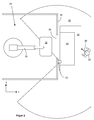
- the sensor 22 is positioned and aligned to a suitable position in space. In this example, at the edge of the passage 38 just above the bottom 40. Then, corresponding protective fields 24 and 25 within the detection range 26 of the Sensors 22 defined, dimensioned and aligned, which could be done for example by pulling the mouse 18. Furthermore, in a communication option, not shown, for example, via the keyboard 16, the security information must be entered into the system 10, which could consist in determining how the system should react when the protective field 24 and the warning field 25 are violated. One possible configuration would be, for example, that if the warning field 25 is violated, only a slowdown of the robot 32 takes place and if the protective field 24 is breached an emergency stop of the robot 32 occurs.
- a possible safety test can be to move the object model 28 into the warning field 25 or into the protective field 24, so that warning and protective field are violated and then the reactions of the sensor model 22 and the plant model 20, calculated in the computer and on the Screen to be viewed, observed and judged. If the reactions are safety-related, e.g. the robot 32 does not perform an emergency stop in the event of a protective field violation, then the configuration is classified as inadmissible and must be re-made with changed configuration parameters. Of course, the configuration parameters must be changeable.
- a typical example of such a test would be, for example, the correct switching of protective fields 24. If, for example, the sensor 22 is to activate various protective fields 24, each with different dimensions, depending on the position of the robot 32 Passage 38, a small protective field 24 may be activated, whereas a larger protective field 24 should be active when the robot is close to the passage. Configuration parameters that define the protective field size would have to be be dynamically changeable during a working movement of the robot 32. The correct configuration can then be checked graphically on the screen 14 with the method and system according to the invention in the simplest manner.
- the configuration parameters for the sensor 22, which correspond to a safety-related standard-conforming configuration found using the method and system according to the invention, can then be transferred from the simulation to the real sensor and do not have to be entered again separately into the sensor.
Landscapes
- Engineering & Computer Science (AREA)
- Physics & Mathematics (AREA)
- Geometry (AREA)
- Theoretical Computer Science (AREA)
- General Physics & Mathematics (AREA)
- Computer Hardware Design (AREA)
- Evolutionary Computation (AREA)
- General Engineering & Computer Science (AREA)
- Structural Engineering (AREA)
- Computational Mathematics (AREA)
- Civil Engineering (AREA)
- Mathematical Analysis (AREA)
- Mathematical Optimization (AREA)
- Pure & Applied Mathematics (AREA)
- Architecture (AREA)
- Manipulator (AREA)
- Testing And Monitoring For Control Systems (AREA)
Description
- Die Erfindung betrifft ein System und ein Verfahren zur sicherheitstechnischen Planung, Konfigurierung und Gefährdungsanalyse einer industriellen Anlage mit Gefährdungspotential.
- Für komplexe Maschinen bzw. Fertigungsanlagen gibt es virtuelle Planungs- und Simulationstools, die es den Planern ermöglichen, eine Maschine bzw. Fertigungsanlage so zu planen, dass wesentliche Prozessabläufe in der Simulation validiert und optimiert werden können, ohne dass die Anlage physikalisch aufgebaut bzw. in Betrieb genommen wird. Diese Planungstools berücksichtigen jedoch nicht die sicherheitstechnischen Aspekte, da sie für die eigentliche Funktion der Anlage, beispielsweise das Schweißen einer Karosserie, keine Bedeutung haben.
- Um einen Bediener bzw. Einrichter einer industriellen Anlage, beispielsweise einer Abkantpresse, eines Montageroboters, eines Schweißroboters oder dergleichen, vor Verletzungen durch gefährliche Anlagenteile zu schützen, werden in der Regel Schutzmaßnahmen eingebaut, die Unfälle verhindern. Solche Schutzmaßnahmen umfassen z.B. mechanische Schutzzäune oder optische Sicherheitssensoren, wie z.B. fehlersichere Laserscanner oder Lichtgittersysteme, die im einfachsten Fall einen Bereich (Schutzfeld) optisch daraufhin überwachen, ob eine Bedienperson diesen Schutzbereich durch unzulässigen Eingriff verletzt. Wird durch den Sicherheitssensor eine Schutzfeldverletzung detektiert, kann eine Abschaltung des gefährlichen Anlagenteils erfolgen. Diese Sicherheitssensoren müssen vor dem Betrieb durch ein Konfigurationstool an die applikationsspezifischen Gegebenheiten angepasst werden, z.B. muss die Größe des Schutzfeldes parametriert werden, und in einer Inbetriebnahme hinsichtlich der Wirksamkeit überprüft werden. Oft sind den Schutzfeldern Warnfelder vorgelagert, wo Eingriffe zunächst nur zu einer Warnung führen, um den Schutzfeldeingriff und damit die Absicherung noch rechtzeitig zu verhindern und so die Verfügbarkeit der Anlage zu erhöhen.
- Wird z.B. mit Hilfe eines Laserscanners die Anwesenheit eines unzulässigen Objektes - also zum Beispiel ein Bein einer Bedienperson - im Gefahrenbereich festgestellt, wird ein Nothalt der Maschine bewirkt. Derartige Sicherheitssensoren müssen zuverlässig arbeiten und deshalb hohe Sicherheitsanforderungen, beispielsweise die Norm EN13849 für Maschinensicherheit und die Gerätenorm EN61496 für berührungslos wirkende Schutzeinrichtungen (BWS), erfüllen.
- Solche Sicherheitslaserscanner werden auch an fahrerlosen Transportsystemen (AGV, "Automated Guided Vehicle") eingesetzt, um zu verhindern, dass diese Transportsysteme mit Objekten, die ihren Fahrweg kreuzen, wie z.B. Personen, zusammenstoßen. Da die Zusammenstoßgefahr geschwindigkeitsabhängig ist, weist der Laserscanner anpassbare Schutzfelddimensionen auf, die in Abhängigkeit der Fahrzeuggeschwindigkeit umschaltbar oder in sonstiger Weise veränderbar sind.
- Um die Wirksamkeit der Sicherheitssensoren zu überprüfen, müssen diese erst nach vollständigem Aufbau der Anlage zunächst für die entsprechende Anwendung konfiguriert werden und dann im echten Betrieb, also im komplexen Fertigungsablauf getestet und überprüft werden. Solche Fertigungsabläufe können ein komplexer Montageprozess oder auch eine Fahrt eines fahrerlosen Transportsystems sein.
- Die Überprüfung erfolgt stichprobenartig und sollte alle erdenklichen Fehler umfassen. Das ist in der Realität aber kaum erfüllbar. So können manche Fehlersituationen nur sehr umständlich überprüft und andere nur unvollständig durchgeführt werden. Beispiel solcher Fehlersituationen sind: Kabelbruch, defekter Sensor, Not-Halt durch Eingreifen, etc.
- Manche Fehlersituationen sind nur durch absichtliches Herbeiführen einer gefährlichen Situation prüfbar. Hierzu zählt der unzulässige Eingriff in ein Schutzfeld eines optischen Sensors, beispielsweise eines Sicherheitslaserscanners, der beispielsweise einen Not-Halt eines Anlagenteils zur Folge hat. Dazu muss eine Testperson den Schutzbereich betreten und den Not-Halt provozieren. Dadurch setzt sich die Person immer einer gefährlichen Situation aus. Deshalb erfolgen auch die meisten Unfälle beim Einrichten und Warten einer Anlage und nicht im normalen Betrieb.
- Aus den Proceedings zum VTT Symposium 224 "Global Engineering and Manufacturing in Enterprise Networks GLOBEMEN", Helsinki, 9.-10.12.2002, ISBN 951-38-5739-5, Seiten 219-232 ist ein System nach dem Oberbegriff des Anspruchs 1 bzw. ein Verfahren nach dem Oberbegriff des Anspruchs 7 bekannt.
- Aufgabe der Erfindung ist es, eine Möglichkeit zur verbesserten Überprüfung und Einrichtung von Sicherheitssensoren bereitzustellen, so dass einerseits die Überprüfung und Einrichtung erleichtert ist und andererseits die Sicherheit für den Einrichter erhöht ist.
- Diese Aufgabe wird gelöst durch ein System nach Anspruch 1 sowie ein Verfahren nach Anspruch 7, das dem System entspricht und ein entsprechendes Computerprogramm nach Anspruch 10.
- Das erfindungsgemäße System zur sicherheitstechnischen Planung, Konfigurierung und Analyse einer industriellen Anlage mit Gefährdungspotential umfasst einen Computer mit einem Speicher, in dem die Anlage als 3-D Computermodell hinterlegt ist, wobei das Anlagenmodell die Arbeitsbewegungen der Anlage dreidimensional simulieren kann und in dem ein 3-D Computermodell eines Sicherheitssensors im Speicher hinterlegt ist, wobei das Sensormodell einen mittels Konfigurationsparametern umschaltbare Schutzfelder des Sensors umfassenden Erfassungsbereich des Sensors umfasst und in dem ein 3-D Computermodell eines sicherheitskritischen Objektes hinterlegt ist. Das Objektmodell ist über Eingabemittel, z.B. eine Maus oder eine Tastatur, im virtuellen Raum bewegbar und ist in das Schutzfeld des Sensormodells bringbar. Bei derartiger virtueller Verletzung des Schutzfeldes ist weiter eine Reaktion des Sensormodells und insbesondere des Anlagenmodells darstellbar.
- Mit einem solchen System ist eine Gefährdungsanalyse der Anlage im virtuellen Betrieb aufgrund der Prozessvisualisierung bzw. Simulation durchführbar, so dass bereits mit Hilfe der Simulation mögliche Maßnahmen, Einstellungen und Konfigurationen definiert werden können, die einen späteren Unfall vermeiden helfen. Diese Maßnahmen, Einstellungen, Konfigurationen können beispielsweise sein:
- korrekte Positionierung von Sicherheitssensoren und optimale Positionierung der Sicherheitslaserscanner im Produktionslayout durch die Möglichkeiten der virtuellen 3D-Anlagensicht,
- korrekte Dimensionierung von Schutzfeldern der Sensoren,
- virtuelle Überprüfung der Anlagenergonomie für den Bediener im Zusammenspiel mit der Sicherheitseinrichtung für optimierte Produktivität,
- Überprüfung aller Anlagenzustände im virtuellen Funktionsablauf mit zeitlichem Abgleich erforderlicher Umschaltungen von Schutzfeldern,
- Simulation des Systemverhaltens bei Ansprechen der Sicherheitsfunktion und anschließendem Wiederanlauf der Maschine bis zur vollen Produktionsgeschwindigkeit,
- Finden von Abschattungen,
- Auflösungen im Schutzfeld,
- Fehleranzeigen,
- Sensorausgangssignale im Fehlerfall,
- Gefundene Parameter können abgespeichert und von dem System an den realen Sicherheitssensor übertragen werden.
- Durch die Erfindung ist es somit möglich, optische Sicherheitssensoren in einem virtuellen Planungs- und Simulationstool zu integrieren und die kompletten sicherheitstechnischen Aufgaben in dem Simulationstool auszuführen. So kann mit der Erfindung ein System und ein Verfahren bereitgestellt werden, in dem es möglich ist, die Gefahrenanalyse, Planung, Projektierung, Inbetriebnahme, Überprüfung und Konfigurationseinstellungen der sicherheitstechnischen Komponenten einfach und ohne Gefährdung des Einrichters vorzunehmen. Dabei werden die normativen Anforderungen in der Simulation verifiziert und die Reaktion auf Fehler bzw. das Systemverhalten, z.B. das Bremsverhalten eines AGV bei max. Beladung oder die Anhaltewegstrecke eines Roboters bei max. Last am TCP (Tool Center Point), überprüft.
- Die Erfindung ermöglicht es dem Steuerungstechniker, das virtuelle Modell der Maschine oder Arbeitszelle zu nutzen, um verschiedene Gefahrensituationen, die ansonsten nur schwer zu beurteilen sind, in Szenarien zu analysieren. Beispielsweise kann mit der Erfindung relativ schnell, einfach und gefahrlos die Frage beantwortet werden, was bei Umstellung einer Fertigungslinie von Produkt A auf Produkt B in Bezug auf sicherheitstechnische Fragen passiert? Auftretende Probleme können vorab erkannt werden und Lösungen gefunden werden. Bereits Wochen vor der Integration sämtlicher Komponenten und Systeme ist der Steuerungstechniker in der Lage, alle Fehlerbedingungen zu testen. Das erspart kostspielige Ausfallzeiten in der Produktion.
- Dabei ist vorgesehen, dass das Sensormodell Konfigurationsparameter umfasst, um z.B. Schutzfelddimensionierungen oder Schutzfeldausrichtungen anpassen zu können.
- Weitere Merkmale sind Gegenstand der abhängigen Ansprüche.
- In Weiterbildung der Erfindung ist vorgesehen, dass die Konfigurationsparameter denen des realen Sensors entsprechen und veränderbar sind.
- Bevorzugt weist das Sensormodell umschaltbare Schutzfelder auf, die mittels der Konfigurationsparameter umschaltbar sind.
- Um dynamische Änderungen berücksichtigen zu können, ist in Weiterbildung der Erfindung vorgesehen, dass die Konfigurationsparameter dynamisch während einer Arbeitsbewegung des Anlagenmodells veränderbar sind.
- Wenn das Sensormodell Fehlerparameter umfasst, mittels derer sicherheitstechnische Fehler simulierbar sind, und eine Reaktion des Sensormodells und des Anlagenmodells auf die Fehler darstellbar ist, können mögliche Fehler simuliert und deren Folgen erkannt werden.
- Wenn die Schutzfelder des Sensormodells grafisch darstellbar sind, können diese in einfacher Weise auch grafisch, z.B. mittels Ziehen mit einer Computermaus, schnell und einfach in ihren Dimensionen verändert und angepasst werden.
- Die Eigenschaften des Sensormodells und des Objektmodells sollten den Anforderungen von Sicherheitsnormen entsprechen, so dass die mittels der mit dem erfindungsgemäßen System eingerichtete Anlage auch normenkonform ist. Wenn das Sensormodell als Programmmodul ausgebildet ist, kann es in einfacher Weise als "plug-in" in ein vorhandenes Planungstool integriert werden.
- Das erfindungsgemäße Verfahren entspricht dem beschriebenen System und ist als Computerprogramm mit Programmcodemitteln zum Durchführen des Verfahrens realisiert. Das Computerprogramm kann auf einem Speichermedium gespeichert sein.
- Im Folgenden wird die Erfindung anhand eines Ausführungsbeispiels unter Bezugnahme auf die Zeichnung im Einzelnen erläutert:
- Fig. 1
- eine Ausführungsform des erfindungsgemäßen Systems;
- Fig. 2
- eine schematische Darstellung einer Draufsicht auf eine graphische Darstellung einer simulierten Anlage;
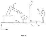
- Fig. 3
- die Anlage aus
Fig. 2 in der Seitenansicht. - Das erfindungsgemäße System 10 zur sicherheitstechnischen Planung, Konfigurierung und Analyse einer industriellen Anlage mit Gefährdungspotential umfasst einen Computer 12 mit einem Bildschirm 14, einer Tastatur 16 und einer Computermaus 18. In einem Speicher des Computers ist eine industrielle Anlage 20 als 3-D Computermodell hinterlegt. Eine solche Anlage 20 ist in
Fig. 2 und3 dargestellt. Es kann sich z.B. um einen Montageroboter, Schweißroboter, Abkantpresse oder dergleichen Maschine handeln. Das Anlagenmodell ist so ausgebildet, dass die Arbeitsbewegungen der Anlage 20 dreidimensional im Computer simuliert werden können. Des Weiteren ist in dem Speicher ein 3-D Computermodell eines Sicherheitssensors 22 hinterlegt, wobei das Sensormodell einen ein Schutzfeld 24 und ein Warnfeld 25 des Sensors 22 umfassenden Erfassungsbereich 26 des Sensors 22 umfasst. Ebenfalls ist ein 3-D Computermodell eines sicherheitskritischen Objektes 28 hinterlegt, das hier als Person 28 dargestellt ist. Das Objektmodell 28 ist über Eingabemittel, z.B. die Maus 18 oder die Tastatur 16, im virtuellen Raum bewegbar (Pfeil 30). - In dem Ausführungsbeispiel umfasst die Anlage 20 einen Roboter 32, ein vom Roboter zu bearbeitendes Werkstück 34 und einen Schutzzaun 36.
- Im Folgenden soll das erfindungsgemäße Verfahren anhand der schematischen Darstellungen der
Fig. 2 und3 erläutert werden. - Das Verfahren dient zur sicherheitstechnischen Planung, Konfigurierung und Analyse der industriellen Anlage 20. Das 3-D Anlagenmodell umfast den Roboter 32, das vom Roboter zu bearbeitende Werkstück 34 und den Schutzzaun 36. In der dargestellten Simulation, die in der Regel auf dem Bildschirm 14 dargestellt wird, sind alle Arbeitsbewegungen der Anlage 20 dreidimensional simulierbar.
- Es könnte nun beispielsweise die Aufgabe für einen Planer bestehen, den Durchgang 38 mit dem Sicherheitssensor 22 abzusichern, so dass der Durchgang 38 nur dann für eine Person 28 frei zugänglich ist, wenn der Roboter 32 sich in einem gefahrlosen Zustand befindet. Dazu wird zunächst der Sensor 22 an eine geeignete Position im Raum positioniert und ausgerichtet. In diesem Beispiel am Rande des Durchgangs 38 knapp oberhalb des Bodens 40. Dann müssen entsprechende Schutzfelder 24 und 25 innerhalb des Erfassungsbereichs 26 des Sensors 22 definiert, dimensioniert und ausgerichtet werden, was z.B. durch Ziehen mit der Maus 18 erfolgen könnte. Des weiteren muss in einer nicht dargestellten Kommunikationsmöglichkeit, beispielsweise über die Tastatur 16, dem System 10 die Sicherheitsinformationen eingegeben werden, die darin bestehen könnten festzulegen, wie die Anlage reagieren soll, wenn das Schutzfeld 24 und das Warnfeld 25 verletzt werden. Eine mögliche Konfiguration wäre z.B., dass bei Verletzung des Warnfeldes 25 lediglich eine Verlangsamung des Roboters 32 erfolgt und bei Verletzung des Schutzfeldes 24 ein Not-Halt des Roboters 32.
- Nun kann ein möglicher Sicherheitstest darin bestehen, das Objektmodell 28 in das Warnfeld 25 oder in das Schutzfeld 24 zu bewegen, so dass Warn- und Schutzfeld verletzt werden und dann die Reaktionen des Sensormodells 22 und des Anlagenmodells 20, die im Computer errechnet und auf dem Bildschirm dargestellt werden, zu beobachten und zu beurteilen. Sind die Reaktionen in sicherheitstechnischer Hinsicht falsch, wenn z.B. der Roboter 32 keinen Not-Halt bei Schutzfeldverletzung durchführt, dann wird die Konfiguration als unzulässig klassifiziert und muss mit geänderten Konfigurationsparametern neu vorgenommen werden. Dazu müssen die Konfigurationsparameter selbstverständlich veränderbar sein.
- Auf diese Weise können die verschiedensten, eingangs beispielhaft aufgezählten Maßnahmen, Einstellungen, Konfigurationen und Fehlersituationen durchgespielt und geprüft werden, bis schließlich eine sicherheitstechnisch unbedenkliche und den Sicherheitsnormen entsprechende Auslegung gefunden ist.
- Ein typisches Beispiel für eine solche Prüfung wäre z.B. auch die korrekte Umschaltung von Schutzfeldern 24. Wenn z.B. der Sensor 22 verschiedene Schutzfelder 24, mit jeweils unterschiedlichen Dimensionen, aktivieren soll und zwar abhängig von der Position des Roboters 32. Ist der Roboter 32 weit entfernt vom Durchgang 38 kann ein kleines Schutzfeld 24 aktiviert sein, wohingegen ein größeres Schutzfeld 24 aktiv sein sollte, wenn der Roboter nahe am Durchgang ist. Konfigurationsparameter, die die Schutzfeldgröße definieren, müssten dafür dynamisch während einer Arbeitsbewegung des Roboters 32 veränderbar sein. Die korrekte Konfiguration kann dann mit dem erfindungsgemäßen Verfahren und System in einfachster Weise grafisch auf dem Bildschirm 14 geprüft werden.
- Die Konfigurationsparameter für den Sensor 22, die einer mit dem erfindungsgemäßen Verfahren und System gefundenen sicherheitstechnisch normenkonformen Konfiguration entsprechen, sind dann aus der Simulation heraus an den realen Sensor übermittelbar und müssen nicht noch einmal separat in den Sensor eingegeben werden.
Claims (10)
- System zur sicherheitstechnischen Planung, Konfigurierung und Analyse einer industriellen Anlage (20) mit Gefährdungspotential, mit einem Computer (12), wobei die Anlage als 3-D Computermodell in einem Speicher des Computers hinterlegt ist, wobei das Anlagenmodell die Arbeitsbewegungen der Anlage (20) dreidimensional simulieren kann, und ein 3-D Computermodell eines Sicherheitssensors (22) sowie ein 3-D Computermodell eines sicherheitskritischen Objektes (28) im Speicher hinterlegt sind, dadurch gekennzeichnet, dass das Sensormodell einen Erfassungsbereich (26) des Sensors umfasst, der grafisch darstellbare Schutzfelder (24, 25) umfasst, die mittels Konfigurationsparametern in ihren Dimensionierungen oder Ausrichtungen anpassbar und umschaltbar sind, wobei das Objektmodell über Eingabemittel (16, 18) im virtuellen Raum bewegbar ist und in ein Schutzfeld (24, 25) des Sensormodells (22) bringbar ist, und bei derartiger Verletzung des Schutzfeldes (24, 25) eine Reaktion des Sensormodells (22) und des Anlagenmodells (20) darstellbar ist.
- System nach Anspruch 1, dadurch gekennzeichnet, dass die Konfigurationsparameter denen des realen Sensors entsprechen und veränderbar sind.
- System nach einem der vorhergehenden Ansprüche, dadurch gekennzeichnet, dass die Konfigurationsparameter dynamisch während einer Arbeitsbewegung des Anlagenmodells veränderbar sind.
- System nach einem der vorhergehenden Ansprüche, dadurch gekennzeichnet, dass das Sensormodell Fehlerparameter umfasst, mittels derer sicherheitstechnische Fehler simulierbar sind, und eine Reaktion des Sensormodells und des Anlagenmodells auf die Fehler darstellbar ist.
- System nach einem der vorhergehenden Ansprüche, dadurch gekennzeichnet, dass die Eigenschaften des Sensormodells und des Objektmodells die Anforderungen von Sicherheitsnormen simulieren.
- System nach einem der vorhergehenden Ansprüche, dadurch gekennzeichnet, dass das Sensormodell als Programmmodul zur Verfügung steht.
- Verfahren zur sicherheitstechnischen Planung, Konfigurierung und Analyse einer industriellen Anlage mit Gefährdungspotential mit einem System nach einem der vorhergehenden Ansprüche, bei dem mit einem Computer ein 3-D Computermodell der Anlage dargestellt wird, das die Arbeitsbewegungen der Anlage dreidimensional simulieren kann, ein 3-D Computermodell eines Sicherheitssensors dargestellt wird und ein 3-D Computermodell eines sicherheitskritischen Objektes dargestellt wird und bei Simulierung von sicherheitstechnischen Fehlfunktionen am Sensormodell eine Reaktion des Anlagenmodells im Computer errechnet und dargestellt wird, dadurch gekennzeichnet, dass mittels Konfigurationsparametern dimensionierbare, ausrichtbare und umschaltbare Schutzfelder des Sensors grafisch dargestellt werden und dass das Objekt im virtuellen Raum bewegbar und in ein Schutzfeld des Sensormodells bringbar ist und bei derartiger Verletzung des Schutzfeldes eine Reaktion des Sensormodells darstellbar ist.
- Verfahren nach Anspruch 7, dadurch gekennzeichnet, dass mit der Simulation geeignete Konfigurationsparameter für das Sensormodell gefunden werden und die nach der Simulation an den realen Sensor übermittelt werden.
- Computerprogramm mit Programmcodemitteln zum Durchführen eines Verfahrens nach Anspruch 7 oder 8.
- Computerprogrammprodukt mit einem Speichermedium auf dem ein Computerprogramm nach Anspruch 9 gespeichert ist.
Priority Applications (1)
| Application Number | Priority Date | Filing Date | Title |
|---|---|---|---|
| EP10159937.1A EP2378445B1 (de) | 2010-04-14 | 2010-04-14 | System und Verfahren zur sicherheitstechnischen Planung einer industriellen Anlage mit Gefährdungspotential |
Applications Claiming Priority (1)
| Application Number | Priority Date | Filing Date | Title |
|---|---|---|---|
| EP10159937.1A EP2378445B1 (de) | 2010-04-14 | 2010-04-14 | System und Verfahren zur sicherheitstechnischen Planung einer industriellen Anlage mit Gefährdungspotential |
Publications (2)
| Publication Number | Publication Date |
|---|---|
| EP2378445A1 EP2378445A1 (de) | 2011-10-19 |
| EP2378445B1 true EP2378445B1 (de) | 2016-05-11 |
Family
ID=42594727
Family Applications (1)
| Application Number | Title | Priority Date | Filing Date |
|---|---|---|---|
| EP10159937.1A Active EP2378445B1 (de) | 2010-04-14 | 2010-04-14 | System und Verfahren zur sicherheitstechnischen Planung einer industriellen Anlage mit Gefährdungspotential |
Country Status (1)
| Country | Link |
|---|---|
| EP (1) | EP2378445B1 (de) |
Cited By (3)
| Publication number | Priority date | Publication date | Assignee | Title |
|---|---|---|---|---|
| DE202020106491U1 (de) | 2020-11-12 | 2022-02-16 | Sick Ag | Visualisieren eines Schutzfeldes |
| DE102020129823A1 (de) | 2020-11-12 | 2022-05-12 | Sick Ag | Visualisieren eines Schutzfeldes |
| EP4385676A1 (de) | 2022-12-12 | 2024-06-19 | Sick Ag | Validierung einer pose eines roboters und von sensordaten eines mit dem roboter mitbewegten sensors |
Families Citing this family (8)
| Publication number | Priority date | Publication date | Assignee | Title |
|---|---|---|---|---|
| US9430589B2 (en) * | 2013-02-05 | 2016-08-30 | Rockwell Automation Technologies, Inc. | Safety automation builder |
| CN103279599B (zh) * | 2013-05-15 | 2015-10-07 | 西北工业大学 | 一种基于交互特征偶的产品建模方法 |
| DE102015220495A1 (de) | 2015-10-21 | 2017-04-27 | Kuka Roboter Gmbh | Schutzfeldanpassung eines Manipulatorsystems |
| DE102015220493A1 (de) * | 2015-10-21 | 2017-04-27 | Kuka Roboter Gmbh | Verifikation einer Position eines Manipulatorsystems |
| US11493908B2 (en) * | 2018-11-13 | 2022-11-08 | Rockwell Automation Technologies, Inc. | Industrial safety monitoring configuration using a digital twin |
| CN113927213A (zh) * | 2020-07-13 | 2022-01-14 | 一汽-大众汽车有限公司 | 用于提供三维安全组合模块的方法和装置 |
| DE202021105907U1 (de) | 2021-10-28 | 2023-01-31 | Sick Ag | Vorrichtung zum Programmieren und/oder Betreiben einer beweglichen Maschine, insbesondere eines Roboters |
| EP4173766B1 (de) | 2021-10-28 | 2024-07-10 | Sick Ag | Vorrichtung und verfahren zum programmieren und/oder betreiben einer beweglichen maschine, insbesondere eines roboters |
Family Cites Families (2)
| Publication number | Priority date | Publication date | Assignee | Title |
|---|---|---|---|---|
| US7237109B2 (en) * | 2003-01-28 | 2007-06-26 | Fisher- Rosemount Systems, Inc. | Integrated security in a process plant having a process control system and a safety system |
| EP1785745A1 (de) * | 2005-11-10 | 2007-05-16 | Omron Electronics Manufacturing of Germany GmbH | Verfahren und Bedieneinheit zum Konfigurieren und Überwachen einer Einrichtung mit funktionaler Sicherheit |
-
2010
- 2010-04-14 EP EP10159937.1A patent/EP2378445B1/de active Active
Non-Patent Citations (1)
| Title |
|---|
| None * |
Cited By (5)
| Publication number | Priority date | Publication date | Assignee | Title |
|---|---|---|---|---|
| DE202020106491U1 (de) | 2020-11-12 | 2022-02-16 | Sick Ag | Visualisieren eines Schutzfeldes |
| DE102020129823A1 (de) | 2020-11-12 | 2022-05-12 | Sick Ag | Visualisieren eines Schutzfeldes |
| EP4000815A1 (de) | 2020-11-12 | 2022-05-25 | Sick Ag | Visualisieren eines schutzfeldes |
| DE102020129823B4 (de) | 2020-11-12 | 2022-07-07 | Sick Ag | Visualisieren eines Schutzfeldes |
| EP4385676A1 (de) | 2022-12-12 | 2024-06-19 | Sick Ag | Validierung einer pose eines roboters und von sensordaten eines mit dem roboter mitbewegten sensors |
Also Published As
| Publication number | Publication date |
|---|---|
| EP2378445A1 (de) | 2011-10-19 |
Similar Documents
| Publication | Publication Date | Title |
|---|---|---|
| EP2378445B1 (de) | System und Verfahren zur sicherheitstechnischen Planung einer industriellen Anlage mit Gefährdungspotential | |
| EP2353052B1 (de) | Sicherheitssteuerung und verfahren zum steuern einer automatisierten anlage | |
| EP2023160B1 (de) | Dreidimensionale Raumüberwachung mit Konfigurationsmodus zum Bestimmen der Schutzfelder | |
| DE102016125595B4 (de) | Zugangsabsicherungssystem | |
| EP1906281B1 (de) | Verfahren und System zur Auslegung und Überprüfung von Sicherheitsbereichen eines Roboters | |
| EP3189947A1 (de) | Verfahren zum konfigurieren und zum betreiben einer überwachten automatisierten arbeitszelle und konfigurationsvorrichtung | |
| EP3819088A1 (de) | Verfahren zur bestimmung eines sicherheitsbereiches und zur bahnplanung für roboter | |
| EP2977148A1 (de) | Verfahren und vorrichtung zum steuern eines roboters | |
| WO2019025248A1 (de) | Verfahren und system zum überprüfen und/oder modifizieren eines arbeitsprozesses eines roboters | |
| EP3323565B1 (de) | Verfahren und vorrichtung zur inbetriebnahme eines mehrachssystems | |
| DE102021208279B4 (de) | Integration einer Risikobeurteilung einer Kollision zwischen einem robotischen Gerät und einer menschlichen Bedienperson | |
| DE102020129823B4 (de) | Visualisieren eines Schutzfeldes | |
| EP4385676B1 (de) | Validierung einer pose eines roboters und von sensordaten eines mit dem roboter mitbewegten sensors | |
| DE102015219369A1 (de) | Sicherheitseinrichtung für eine Strahlbearbeitungsvorrichtung und Verfahren | |
| EP2835699B1 (de) | Vorrichtung und Verfahren zum Konfigurieren und/oder Programmieren einer Sicherheitssteuerung | |
| DE202020106491U1 (de) | Visualisieren eines Schutzfeldes | |
| EP3791375B1 (de) | Verfahren und vorrichtung zur gegenseitigen überwachung und/oder kontrolle autonomer technischer systeme | |
| DE102004020994B4 (de) | Verfahren und Vorrichtung zum computergestützten Konstruieren einer sicherheitsgerichteten elektrischen Schaltung | |
| EP3731043A1 (de) | Verfahren zur sicherheitsbeurteilung, computerprogramm, maschinenlesbares speichermedium und sicherheitsbeurteilungseinrichtung | |
| EP3696629A1 (de) | Verfahren zur überprüfung einer industriellen anlage, computerprogramm, computerlesbares medium und system | |
| EP3980223B1 (de) | Verfahren und system zur automatischen absicherung eines mittels einer mobilen bedienvorrichtung gesteuerten betriebs eines robotersystems | |
| DE102009027269A1 (de) | System und Verfahren zur Überwachung des Zustands einer Maschine | |
| DE102023200866A1 (de) | Verfahren zum Ermitteln möglicher Sicherheitsrisiken eines Robotersystems | |
| EP3719595B1 (de) | Bedienung einer technischen anlage | |
| WO2023110490A1 (de) | Verfahren zum zuordnen einer not-halt-funktionalität und automatisierungsanlage |
Legal Events
| Date | Code | Title | Description |
|---|---|---|---|
| AK | Designated contracting states |
Kind code of ref document: A1 Designated state(s): AT BE BG CH CY CZ DE DK EE ES FI FR GB GR HR HU IE IS IT LI LT LU LV MC MK MT NL NO PL PT RO SE SI SK SM TR |
|
| AX | Request for extension of the european patent |
Extension state: AL BA ME RS |
|
| PUAI | Public reference made under article 153(3) epc to a published international application that has entered the european phase |
Free format text: ORIGINAL CODE: 0009012 |
|
| 17P | Request for examination filed |
Effective date: 20120301 |
|
| 17Q | First examination report despatched |
Effective date: 20120827 |
|
| RIC1 | Information provided on ipc code assigned before grant |
Ipc: G05B 19/042 20060101ALN20151201BHEP Ipc: G06F 17/50 20060101AFI20151201BHEP |
|
| RIC1 | Information provided on ipc code assigned before grant |
Ipc: G06F 17/50 20060101AFI20151204BHEP Ipc: G05B 19/042 20060101ALN20151204BHEP |
|
| GRAP | Despatch of communication of intention to grant a patent |
Free format text: ORIGINAL CODE: EPIDOSNIGR1 |
|
| GRAS | Grant fee paid |
Free format text: ORIGINAL CODE: EPIDOSNIGR3 |
|
| RIC1 | Information provided on ipc code assigned before grant |
Ipc: G06F 17/50 20060101AFI20160224BHEP Ipc: G05B 19/042 20060101ALN20160224BHEP |
|
| INTG | Intention to grant announced |
Effective date: 20160309 |
|
| GRAA | (expected) grant |
Free format text: ORIGINAL CODE: 0009210 |
|
| AK | Designated contracting states |
Kind code of ref document: B1 Designated state(s): AT BE BG CH CY CZ DE DK EE ES FI FR GB GR HR HU IE IS IT LI LT LU LV MC MK MT NL NO PL PT RO SE SI SK SM TR |
|
| REG | Reference to a national code |
Ref country code: GB Ref legal event code: FG4D Free format text: NOT ENGLISH |
|
| REG | Reference to a national code |
Ref country code: CH Ref legal event code: EP |
|
| REG | Reference to a national code |
Ref country code: AT Ref legal event code: REF Ref document number: 799158 Country of ref document: AT Kind code of ref document: T Effective date: 20160515 |
|
| REG | Reference to a national code |
Ref country code: IE Ref legal event code: FG4D Free format text: LANGUAGE OF EP DOCUMENT: GERMAN |
|
| REG | Reference to a national code |
Ref country code: DE Ref legal event code: R096 Ref document number: 502010011637 Country of ref document: DE |
|
| REG | Reference to a national code |
Ref country code: LT Ref legal event code: MG4D |
|
| REG | Reference to a national code |
Ref country code: NL Ref legal event code: MP Effective date: 20160511 |
|
| PG25 | Lapsed in a contracting state [announced via postgrant information from national office to epo] |
Ref country code: FI Free format text: LAPSE BECAUSE OF FAILURE TO SUBMIT A TRANSLATION OF THE DESCRIPTION OR TO PAY THE FEE WITHIN THE PRESCRIBED TIME-LIMIT Effective date: 20160511 Ref country code: NL Free format text: LAPSE BECAUSE OF FAILURE TO SUBMIT A TRANSLATION OF THE DESCRIPTION OR TO PAY THE FEE WITHIN THE PRESCRIBED TIME-LIMIT Effective date: 20160511 Ref country code: NO Free format text: LAPSE BECAUSE OF FAILURE TO SUBMIT A TRANSLATION OF THE DESCRIPTION OR TO PAY THE FEE WITHIN THE PRESCRIBED TIME-LIMIT Effective date: 20160811 Ref country code: LT Free format text: LAPSE BECAUSE OF FAILURE TO SUBMIT A TRANSLATION OF THE DESCRIPTION OR TO PAY THE FEE WITHIN THE PRESCRIBED TIME-LIMIT Effective date: 20160511 |
|
| PG25 | Lapsed in a contracting state [announced via postgrant information from national office to epo] |
Ref country code: LV Free format text: LAPSE BECAUSE OF FAILURE TO SUBMIT A TRANSLATION OF THE DESCRIPTION OR TO PAY THE FEE WITHIN THE PRESCRIBED TIME-LIMIT Effective date: 20160511 Ref country code: GR Free format text: LAPSE BECAUSE OF FAILURE TO SUBMIT A TRANSLATION OF THE DESCRIPTION OR TO PAY THE FEE WITHIN THE PRESCRIBED TIME-LIMIT Effective date: 20160812 Ref country code: PT Free format text: LAPSE BECAUSE OF FAILURE TO SUBMIT A TRANSLATION OF THE DESCRIPTION OR TO PAY THE FEE WITHIN THE PRESCRIBED TIME-LIMIT Effective date: 20160912 Ref country code: HR Free format text: LAPSE BECAUSE OF FAILURE TO SUBMIT A TRANSLATION OF THE DESCRIPTION OR TO PAY THE FEE WITHIN THE PRESCRIBED TIME-LIMIT Effective date: 20160511 Ref country code: ES Free format text: LAPSE BECAUSE OF FAILURE TO SUBMIT A TRANSLATION OF THE DESCRIPTION OR TO PAY THE FEE WITHIN THE PRESCRIBED TIME-LIMIT Effective date: 20160511 Ref country code: SE Free format text: LAPSE BECAUSE OF FAILURE TO SUBMIT A TRANSLATION OF THE DESCRIPTION OR TO PAY THE FEE WITHIN THE PRESCRIBED TIME-LIMIT Effective date: 20160511 |
|
| PG25 | Lapsed in a contracting state [announced via postgrant information from national office to epo] |
Ref country code: IT Free format text: LAPSE BECAUSE OF FAILURE TO SUBMIT A TRANSLATION OF THE DESCRIPTION OR TO PAY THE FEE WITHIN THE PRESCRIBED TIME-LIMIT Effective date: 20160511 |
|
| PG25 | Lapsed in a contracting state [announced via postgrant information from national office to epo] |
Ref country code: EE Free format text: LAPSE BECAUSE OF FAILURE TO SUBMIT A TRANSLATION OF THE DESCRIPTION OR TO PAY THE FEE WITHIN THE PRESCRIBED TIME-LIMIT Effective date: 20160511 Ref country code: DK Free format text: LAPSE BECAUSE OF FAILURE TO SUBMIT A TRANSLATION OF THE DESCRIPTION OR TO PAY THE FEE WITHIN THE PRESCRIBED TIME-LIMIT Effective date: 20160511 Ref country code: CZ Free format text: LAPSE BECAUSE OF FAILURE TO SUBMIT A TRANSLATION OF THE DESCRIPTION OR TO PAY THE FEE WITHIN THE PRESCRIBED TIME-LIMIT Effective date: 20160511 Ref country code: SK Free format text: LAPSE BECAUSE OF FAILURE TO SUBMIT A TRANSLATION OF THE DESCRIPTION OR TO PAY THE FEE WITHIN THE PRESCRIBED TIME-LIMIT Effective date: 20160511 Ref country code: RO Free format text: LAPSE BECAUSE OF FAILURE TO SUBMIT A TRANSLATION OF THE DESCRIPTION OR TO PAY THE FEE WITHIN THE PRESCRIBED TIME-LIMIT Effective date: 20160511 |
|
| REG | Reference to a national code |
Ref country code: DE Ref legal event code: R097 Ref document number: 502010011637 Country of ref document: DE |
|
| PG25 | Lapsed in a contracting state [announced via postgrant information from national office to epo] |
Ref country code: SM Free format text: LAPSE BECAUSE OF FAILURE TO SUBMIT A TRANSLATION OF THE DESCRIPTION OR TO PAY THE FEE WITHIN THE PRESCRIBED TIME-LIMIT Effective date: 20160511 Ref country code: PL Free format text: LAPSE BECAUSE OF FAILURE TO SUBMIT A TRANSLATION OF THE DESCRIPTION OR TO PAY THE FEE WITHIN THE PRESCRIBED TIME-LIMIT Effective date: 20160511 |
|
| PLBE | No opposition filed within time limit |
Free format text: ORIGINAL CODE: 0009261 |
|
| STAA | Information on the status of an ep patent application or granted ep patent |
Free format text: STATUS: NO OPPOSITION FILED WITHIN TIME LIMIT |
|
| 26N | No opposition filed |
Effective date: 20170214 |
|
| REG | Reference to a national code |
Ref country code: FR Ref legal event code: PLFP Year of fee payment: 8 |
|
| PG25 | Lapsed in a contracting state [announced via postgrant information from national office to epo] |
Ref country code: SI Free format text: LAPSE BECAUSE OF FAILURE TO SUBMIT A TRANSLATION OF THE DESCRIPTION OR TO PAY THE FEE WITHIN THE PRESCRIBED TIME-LIMIT Effective date: 20160511 |
|
| PG25 | Lapsed in a contracting state [announced via postgrant information from national office to epo] |
Ref country code: MC Free format text: LAPSE BECAUSE OF FAILURE TO SUBMIT A TRANSLATION OF THE DESCRIPTION OR TO PAY THE FEE WITHIN THE PRESCRIBED TIME-LIMIT Effective date: 20160511 |
|
| REG | Reference to a national code |
Ref country code: IE Ref legal event code: MM4A |
|
| PG25 | Lapsed in a contracting state [announced via postgrant information from national office to epo] |
Ref country code: LU Free format text: LAPSE BECAUSE OF NON-PAYMENT OF DUE FEES Effective date: 20170414 |
|
| REG | Reference to a national code |
Ref country code: BE Ref legal event code: MM Effective date: 20170430 |
|
| REG | Reference to a national code |
Ref country code: FR Ref legal event code: PLFP Year of fee payment: 9 |
|
| PG25 | Lapsed in a contracting state [announced via postgrant information from national office to epo] |
Ref country code: IE Free format text: LAPSE BECAUSE OF NON-PAYMENT OF DUE FEES Effective date: 20170414 |
|
| PG25 | Lapsed in a contracting state [announced via postgrant information from national office to epo] |
Ref country code: BE Free format text: LAPSE BECAUSE OF NON-PAYMENT OF DUE FEES Effective date: 20170430 |
|
| REG | Reference to a national code |
Ref country code: AT Ref legal event code: MM01 Ref document number: 799158 Country of ref document: AT Kind code of ref document: T Effective date: 20170414 |
|
| PG25 | Lapsed in a contracting state [announced via postgrant information from national office to epo] |
Ref country code: AT Free format text: LAPSE BECAUSE OF NON-PAYMENT OF DUE FEES Effective date: 20170414 |
|
| PG25 | Lapsed in a contracting state [announced via postgrant information from national office to epo] |
Ref country code: MT Free format text: LAPSE BECAUSE OF FAILURE TO SUBMIT A TRANSLATION OF THE DESCRIPTION OR TO PAY THE FEE WITHIN THE PRESCRIBED TIME-LIMIT Effective date: 20160511 |
|
| PG25 | Lapsed in a contracting state [announced via postgrant information from national office to epo] |
Ref country code: HU Free format text: LAPSE BECAUSE OF FAILURE TO SUBMIT A TRANSLATION OF THE DESCRIPTION OR TO PAY THE FEE WITHIN THE PRESCRIBED TIME-LIMIT; INVALID AB INITIO Effective date: 20100414 |
|
| PG25 | Lapsed in a contracting state [announced via postgrant information from national office to epo] |
Ref country code: BG Free format text: LAPSE BECAUSE OF FAILURE TO SUBMIT A TRANSLATION OF THE DESCRIPTION OR TO PAY THE FEE WITHIN THE PRESCRIBED TIME-LIMIT Effective date: 20160511 |
|
| PG25 | Lapsed in a contracting state [announced via postgrant information from national office to epo] |
Ref country code: CY Free format text: LAPSE BECAUSE OF NON-PAYMENT OF DUE FEES Effective date: 20160511 |
|
| REG | Reference to a national code |
Ref country code: DE Ref legal event code: R079 Ref document number: 502010011637 Country of ref document: DE Free format text: PREVIOUS MAIN CLASS: G06F0017500000 Ipc: G06F0030000000 |
|
| PG25 | Lapsed in a contracting state [announced via postgrant information from national office to epo] |
Ref country code: MK Free format text: LAPSE BECAUSE OF FAILURE TO SUBMIT A TRANSLATION OF THE DESCRIPTION OR TO PAY THE FEE WITHIN THE PRESCRIBED TIME-LIMIT Effective date: 20160511 |
|
| PG25 | Lapsed in a contracting state [announced via postgrant information from national office to epo] |
Ref country code: TR Free format text: LAPSE BECAUSE OF FAILURE TO SUBMIT A TRANSLATION OF THE DESCRIPTION OR TO PAY THE FEE WITHIN THE PRESCRIBED TIME-LIMIT Effective date: 20160511 |
|
| PG25 | Lapsed in a contracting state [announced via postgrant information from national office to epo] |
Ref country code: IS Free format text: LAPSE BECAUSE OF FAILURE TO SUBMIT A TRANSLATION OF THE DESCRIPTION OR TO PAY THE FEE WITHIN THE PRESCRIBED TIME-LIMIT Effective date: 20160911 |
|
| PGFP | Annual fee paid to national office [announced via postgrant information from national office to epo] |
Ref country code: CH Payment date: 20210422 Year of fee payment: 12 |
|
| PGFP | Annual fee paid to national office [announced via postgrant information from national office to epo] |
Ref country code: GB Payment date: 20220425 Year of fee payment: 13 Ref country code: FR Payment date: 20220420 Year of fee payment: 13 |
|
| REG | Reference to a national code |
Ref country code: CH Ref legal event code: PL |
|
| PG25 | Lapsed in a contracting state [announced via postgrant information from national office to epo] |
Ref country code: LI Free format text: LAPSE BECAUSE OF NON-PAYMENT OF DUE FEES Effective date: 20220430 Ref country code: CH Free format text: LAPSE BECAUSE OF NON-PAYMENT OF DUE FEES Effective date: 20220430 |
|
| GBPC | Gb: european patent ceased through non-payment of renewal fee |
Effective date: 20230414 |
|
| PG25 | Lapsed in a contracting state [announced via postgrant information from national office to epo] |
Ref country code: GB Free format text: LAPSE BECAUSE OF NON-PAYMENT OF DUE FEES Effective date: 20230414 |
|
| PG25 | Lapsed in a contracting state [announced via postgrant information from national office to epo] |
Ref country code: GB Free format text: LAPSE BECAUSE OF NON-PAYMENT OF DUE FEES Effective date: 20230414 Ref country code: FR Free format text: LAPSE BECAUSE OF NON-PAYMENT OF DUE FEES Effective date: 20230430 |
|
| PGFP | Annual fee paid to national office [announced via postgrant information from national office to epo] |
Ref country code: DE Payment date: 20250417 Year of fee payment: 16 |