EP2383435A1 - Hohle Innenführung einer Turbinenschaufel - Google Patents
Hohle Innenführung einer Turbinenschaufel Download PDFInfo
- Publication number
- EP2383435A1 EP2383435A1 EP10161435A EP10161435A EP2383435A1 EP 2383435 A1 EP2383435 A1 EP 2383435A1 EP 10161435 A EP10161435 A EP 10161435A EP 10161435 A EP10161435 A EP 10161435A EP 2383435 A1 EP2383435 A1 EP 2383435A1
- Authority
- EP
- European Patent Office
- Prior art keywords
- cooling fluid
- rail
- hole
- inner platform
- guide vane
- Prior art date
- Legal status (The legal status is an assumption and is not a legal conclusion. Google has not performed a legal analysis and makes no representation as to the accuracy of the status listed.)
- Withdrawn
Links
- 239000012809 cooling fluid Substances 0.000 claims abstract description 90
- 238000001816 cooling Methods 0.000 claims abstract description 17
- 239000012530 fluid Substances 0.000 claims abstract description 11
- 238000007789 sealing Methods 0.000 claims description 10
- 238000000034 method Methods 0.000 claims description 7
- 230000035882 stress Effects 0.000 description 7
- 230000008646 thermal stress Effects 0.000 description 4
- 239000000463 material Substances 0.000 description 3
- 238000005266 casting Methods 0.000 description 2
- 238000005336 cracking Methods 0.000 description 2
- 238000012423 maintenance Methods 0.000 description 2
- 230000001052 transient effect Effects 0.000 description 2
- 238000010438 heat treatment Methods 0.000 description 1
- 238000004519 manufacturing process Methods 0.000 description 1
- 230000006903 response to temperature Effects 0.000 description 1
Images


Classifications
-
- F—MECHANICAL ENGINEERING; LIGHTING; HEATING; WEAPONS; BLASTING
- F01—MACHINES OR ENGINES IN GENERAL; ENGINE PLANTS IN GENERAL; STEAM ENGINES
- F01D—NON-POSITIVE DISPLACEMENT MACHINES OR ENGINES, e.g. STEAM TURBINES
- F01D25/00—Component parts, details, or accessories, not provided for in, or of interest apart from, other groups
- F01D25/08—Cooling; Heating; Heat-insulation
- F01D25/12—Cooling
-
- B—PERFORMING OPERATIONS; TRANSPORTING
- B23—MACHINE TOOLS; METAL-WORKING NOT OTHERWISE PROVIDED FOR
- B23P—METAL-WORKING NOT OTHERWISE PROVIDED FOR; COMBINED OPERATIONS; UNIVERSAL MACHINE TOOLS
- B23P15/00—Making specific metal objects by operations not covered by a single other subclass or a group in this subclass
- B23P15/04—Making specific metal objects by operations not covered by a single other subclass or a group in this subclass turbine or like blades from several pieces
-
- F—MECHANICAL ENGINEERING; LIGHTING; HEATING; WEAPONS; BLASTING
- F01—MACHINES OR ENGINES IN GENERAL; ENGINE PLANTS IN GENERAL; STEAM ENGINES
- F01D—NON-POSITIVE DISPLACEMENT MACHINES OR ENGINES, e.g. STEAM TURBINES
- F01D11/00—Preventing or minimising internal leakage of working-fluid, e.g. between stages
- F01D11/001—Preventing or minimising internal leakage of working-fluid, e.g. between stages for sealing space between stator blade and rotor
-
- F—MECHANICAL ENGINEERING; LIGHTING; HEATING; WEAPONS; BLASTING
- F01—MACHINES OR ENGINES IN GENERAL; ENGINE PLANTS IN GENERAL; STEAM ENGINES
- F01D—NON-POSITIVE DISPLACEMENT MACHINES OR ENGINES, e.g. STEAM TURBINES
- F01D11/00—Preventing or minimising internal leakage of working-fluid, e.g. between stages
- F01D11/005—Sealing means between non relatively rotating elements
-
- F—MECHANICAL ENGINEERING; LIGHTING; HEATING; WEAPONS; BLASTING
- F01—MACHINES OR ENGINES IN GENERAL; ENGINE PLANTS IN GENERAL; STEAM ENGINES
- F01D—NON-POSITIVE DISPLACEMENT MACHINES OR ENGINES, e.g. STEAM TURBINES
- F01D5/00—Blades; Blade-carrying members; Heating, heat-insulating, cooling or antivibration means on the blades or the members
- F01D5/12—Blades
- F01D5/14—Form or construction
- F01D5/18—Hollow blades, i.e. blades with cooling or heating channels or cavities; Heating, heat-insulating or cooling means on blades
- F01D5/187—Convection cooling
- F01D5/188—Convection cooling with an insert in the blade cavity to guide the cooling fluid, e.g. forming a separation wall
- F01D5/189—Convection cooling with an insert in the blade cavity to guide the cooling fluid, e.g. forming a separation wall the insert having a tubular cross-section, e.g. airfoil shape
-
- F—MECHANICAL ENGINEERING; LIGHTING; HEATING; WEAPONS; BLASTING
- F01—MACHINES OR ENGINES IN GENERAL; ENGINE PLANTS IN GENERAL; STEAM ENGINES
- F01D—NON-POSITIVE DISPLACEMENT MACHINES OR ENGINES, e.g. STEAM TURBINES
- F01D9/00—Stators
- F01D9/02—Nozzles; Nozzle boxes; Stator blades; Guide conduits, e.g. individual nozzles
- F01D9/04—Nozzles; Nozzle boxes; Stator blades; Guide conduits, e.g. individual nozzles forming ring or sector
- F01D9/042—Nozzles; Nozzle boxes; Stator blades; Guide conduits, e.g. individual nozzles forming ring or sector fixing blades to stators
-
- F—MECHANICAL ENGINEERING; LIGHTING; HEATING; WEAPONS; BLASTING
- F01—MACHINES OR ENGINES IN GENERAL; ENGINE PLANTS IN GENERAL; STEAM ENGINES
- F01D—NON-POSITIVE DISPLACEMENT MACHINES OR ENGINES, e.g. STEAM TURBINES
- F01D9/00—Stators
- F01D9/02—Nozzles; Nozzle boxes; Stator blades; Guide conduits, e.g. individual nozzles
- F01D9/04—Nozzles; Nozzle boxes; Stator blades; Guide conduits, e.g. individual nozzles forming ring or sector
- F01D9/047—Nozzle boxes
-
- F—MECHANICAL ENGINEERING; LIGHTING; HEATING; WEAPONS; BLASTING
- F01—MACHINES OR ENGINES IN GENERAL; ENGINE PLANTS IN GENERAL; STEAM ENGINES
- F01D—NON-POSITIVE DISPLACEMENT MACHINES OR ENGINES, e.g. STEAM TURBINES
- F01D9/00—Stators
- F01D9/06—Fluid supply conduits to nozzles or the like
-
- F—MECHANICAL ENGINEERING; LIGHTING; HEATING; WEAPONS; BLASTING
- F05—INDEXING SCHEMES RELATING TO ENGINES OR PUMPS IN VARIOUS SUBCLASSES OF CLASSES F01-F04
- F05D—INDEXING SCHEME FOR ASPECTS RELATING TO NON-POSITIVE-DISPLACEMENT MACHINES OR ENGINES, GAS-TURBINES OR JET-PROPULSION PLANTS
- F05D2240/00—Components
- F05D2240/10—Stators
- F05D2240/12—Fluid guiding means, e.g. vanes
-
- F—MECHANICAL ENGINEERING; LIGHTING; HEATING; WEAPONS; BLASTING
- F05—INDEXING SCHEMES RELATING TO ENGINES OR PUMPS IN VARIOUS SUBCLASSES OF CLASSES F01-F04
- F05D—INDEXING SCHEME FOR ASPECTS RELATING TO NON-POSITIVE-DISPLACEMENT MACHINES OR ENGINES, GAS-TURBINES OR JET-PROPULSION PLANTS
- F05D2240/00—Components
- F05D2240/80—Platforms for stationary or moving blades
- F05D2240/81—Cooled platforms
-
- F—MECHANICAL ENGINEERING; LIGHTING; HEATING; WEAPONS; BLASTING
- F05—INDEXING SCHEMES RELATING TO ENGINES OR PUMPS IN VARIOUS SUBCLASSES OF CLASSES F01-F04
- F05D—INDEXING SCHEME FOR ASPECTS RELATING TO NON-POSITIVE-DISPLACEMENT MACHINES OR ENGINES, GAS-TURBINES OR JET-PROPULSION PLANTS
- F05D2240/00—Components
- F05D2240/90—Mounting on supporting structures or systems
- F05D2240/91—Mounting on supporting structures or systems on a stationary structure
-
- F—MECHANICAL ENGINEERING; LIGHTING; HEATING; WEAPONS; BLASTING
- F05—INDEXING SCHEMES RELATING TO ENGINES OR PUMPS IN VARIOUS SUBCLASSES OF CLASSES F01-F04
- F05D—INDEXING SCHEME FOR ASPECTS RELATING TO NON-POSITIVE-DISPLACEMENT MACHINES OR ENGINES, GAS-TURBINES OR JET-PROPULSION PLANTS
- F05D2260/00—Function
- F05D2260/20—Heat transfer, e.g. cooling
- F05D2260/201—Heat transfer, e.g. cooling by impingement of a fluid
-
- Y—GENERAL TAGGING OF NEW TECHNOLOGICAL DEVELOPMENTS; GENERAL TAGGING OF CROSS-SECTIONAL TECHNOLOGIES SPANNING OVER SEVERAL SECTIONS OF THE IPC; TECHNICAL SUBJECTS COVERED BY FORMER USPC CROSS-REFERENCE ART COLLECTIONS [XRACs] AND DIGESTS
- Y10—TECHNICAL SUBJECTS COVERED BY FORMER USPC
- Y10T—TECHNICAL SUBJECTS COVERED BY FORMER US CLASSIFICATION
- Y10T29/00—Metal working
- Y10T29/49—Method of mechanical manufacture
- Y10T29/49316—Impeller making
Definitions
- the present invention relates to a guide vane device for a turbine and to a method of producing a guide vane device for a turbine.
- Aerofoils of the guide vanes are formed on an inner platform that extends in a circumferential direction of the turbine shaft. From the inner platform, the aerofoils extend radially outwardly. From the inner platform in radial direction to the center of the turbine shaft an inner rail is attached. The inner rail is used to mount a diaphragm between the surface of the turbine shaft and the inner platform.
- the inner rail is in general thicker and broader than the inner platform to which the inner rail is attached, so that the inner rail reacts slower in response to temperature changes in the turbine with respect to the inner platform. This may result in thermally induced stress and reduces the lifetime of the conventional nozzle guide vane devices.
- the stresses may be reduced by keeping the depth and width of the inner rail to a minimum required. This may also lead to a reduction of the lifetime of the inner rail respectively to the turbine nozzle guide vane and reduces the quality of fixation of the diaphragms.
- US 4,126,405 describes a segment of a turbo machine nozzle that is held tangentially in position by a pair of lugs extending radially from outer and inner bands. Each lug acts as an end cap to prevent leakage of air from one end of the vane.
- EP 1 793 088 A2 discloses a turbine nozzle for a gas turbine engine.
- the turbine nozzle comprises an outer band and an inner band. Between the inner band and the outer band vanes are formed. To the inner band a flange and a forward inner flange is formed, wherein the flanges extend radially inwardly from the inner band.
- US 3,829,233 discloses a seal arrangement for a bladed diaphragm of an axial flow fluid machine, such as a gas turbine.
- the turbine comprises an inner shroud from which the vanes extend radially outwardly with respect to the turbine shaft and from which flanges and ribs extend radially inwardly.
- a seal housing ring or a diaphragm is attached, so that the inner shroud is sealed from the turbine shaft.
- the inner shroud comprises an orifice for cooling fluid, wherein the orifice is spatially located from the flanges and ribs.
- a guide vane device for a turbine comprises an inner platform, a hollow aerofoil and a rail.
- the inner platform comprises a through hole forming a fluid channel for a cooling fluid.
- the inner platform extends in circumferential direction around a shaft of the turbine.
- the hollow aerofoil comprises a cooling opening for exchanging the cooling fluid passing the through hole into or from the hollow aerofoil.
- the hollow aerofoil is fixed to a first surface of the inner platform.
- the rail comprises a recess with a cooling fluid passage, wherein the cooling fluid passage forms a passage for the cooling fluid to the through hole.
- the rail is fixed to a second surface of the inner platform and the rail extends along the second surface in the circumferential direction around the shaft.
- the cooling fluid passage comprises in the circumferential direction at least the dimension of the through hole.
- a method for producing a guide vane device for a turbine is provided.
- an inner platform with the through hole for forming a fluid channel for a cooling fluid is provided.
- the inner platform extends thereby in a circumferential direction around the shaft of the turbine.
- a hollow aerofoil is fixed to a first surface (e.g. which is aligned radially outwardly to the turbine axis) of the inner platform, wherein the hollow aerofoil comprises a cooling opening for exchanging the cooling fluid passing the through hole into or from the hollow aerofoil.
- a rail is fixed to a second surface (e.g.
- the rail comprises a recess with the cooling fluid passage for forming a passage for the cooling fluid.
- the cooling fluid passage comprises in the circumferential direction at least a dimension of the through hole.
- the inner platform extends around the circumferential direction along the turbine shaft.
- the inner platform may comprise an internal cooling channel extending as well in circumferential direction through which cooling fluid may be transported.
- the through hole is formed. With the through hole, the cooling fluid is exchanged into or from the hollow aerofoil.
- the through hole forms a cooling fluid connection to the rail, so that also cooling fluid is exchangeable in a direction to or from the direction to the turbine shaft.
- the rail extends along the second surface of the inner platform in the circumferential direction around the turbine shaft. Moreover, the rail extends radially inwardly to the turbine shaft starting from the second surface.
- the rail provides a defined rigidity in order to fix a sealing element, such as a diaphragm, between the second surface of the rail and a surface of the turbine shaft.
- the rail comprises a recess with a cooling fluid passage.
- the cooling fluid passage forms a channel (that extends radial to the turbine shaft) between the through hole of the inner platform and the space between the inner platform and the turbine shaft.
- the smallest opening or diameter restricts the fluid velocity and thus the cooling efficiency.
- the cooling fluid passage of the rail is equal or larger than the through hole of the inner platform, the cooling fluid cools with the same cooling efficiency the rail and the inner platform.
- the dimension of the through hole denotes in particular the size of the cooling fluid passage and the through hole along the circumferential direction. If the through hole and/or the cooling fluid passage are circular, the dimension denotes for instance the diameter. If the shape of the through hole or the cooling fluid passage is elliptical, the dimension may define the major axis or the transverse diameter, for example. If the shape of the cooling fluid passage and/or the through hole is rectangular, the dimension may denote the length along the circumferential direction. Additionally or alternatively, the term "dimension" denotes the cross-sectional area of the overlapping cross-sections of the cooling fluid passage with the through hole. In other words, the cross-sectional area of the cooling fluid passage is larger than the cross-sectional area of the through hole in the section, where the cooling fluid passage overlaps the cross-section of the through hole.
- the aerofoil comprises a wing profile comprising a trailing edge and a leading edge.
- the working medium flows against the leading edge and is guided by the surface (profile) of the aerofoil to the trailing edge, where the working medium leaves the aerofoil with a predetermined and desired flow direction.
- the leading edge and the trailing edge are connected by an imaginary straight line called the cord.
- the cord of the aerofoil comprises an angle between 0° and 90° degrees to the (circumferential) extending direction.
- the rail is formed in general along the circumferential direction.
- the cooling fluid passage is formed larger than through hole in the overlapping cross-section, so that the maximum mass flow of the cooling fluid is not restricted by the dimension of the cooling fluid passage of the rail. In other words, the cooling fluid passage does not form the smallest passage of the cooling fluid in comparison to the through hole of the inner platform and the aerofoil.
- the cooling fluid cools the inner rail and the inner platform with the same cooling efficiency, the temperature difference of the inner platform and the rail is reduced.
- a larger cooling fluid passage of the rail with respect to the through hole may allow the rail to follow the temperature change rate of the bulk temperature of the rest of the guide vane device elements, such as the inner platform and the hollow aerofoil. This results in less thermal stress during transient and fast changing temperature conditions.
- the thermal stress of the rail when reducing the thermal stress of the rail by adapting the dimension of the cooling fluid passage, the thermal stress of the rail is reduced and damages, such as cracking due to thermal differences, may be reduced.
- the recess is larger than the through hole of the inner platform.
- the recess may be formed like a slotted hole wherein the length of the slotted hole extends in the circumferential direction with respect to the shaft.
- the rail comprises less weight because more material can be removed from the rail.
- the rail is integrally formed within a platform.
- the rail and the inner platform may form a monolithic structure and may be casted in one workstep.
- the guide vane device comprises a further hollow aerofoil.
- the inner platform comprises a further through hole forming a further fluid channel for the cooling fluid.
- the further hollow aerofoil comprises a further cooling opening for receiving the cooling fluid passing the further through hole into the further hollow aerofoil, wherein the further hollow aerofoil is fixed to the first surface of the inner platform.
- the rail comprises a further recess with a further cooling fluid passage forming a further passage for the cooling fluid to the through hole.
- the further cooling fluid passage comprises in circumferential direction at least the dimension of the further through hole.
- the guide vane device may form a segment of a circumferential stator stage of a turbine.
- the segment may comprise only one or a plurality of aerofoils that are attached to the first surface of the inner platform.
- Each segment may be connected to an adjacent guide vane segment in circumferential direction.
- Each guide vane device may be attached to a further guide vane device by a detachable connection.
- the segment may comprise e.g. 3, 4, 5 or more aerofoils.
- the guide vane device (segment) may also form a full (360 degree) section with a plurality of aerofoils.
- damaged guide vane devices guide vane segments
- the maintenance costs are reduced.
- the guide vane device further comprises a diaphragm for sealing the guide vane device with respect to the shaft.
- the rail comprises a mounting section to which the diaphragm is mounted. The rail fixes the diaphragm in such a way, that the diaphragm is kept in a desired position in which the diaphragm seals an inner space between the inner platform and the turbine axis. Due to the proper cooling of the rail by the larger dimension of the through hole, the thermal deformation of the rail is reduced, so that gaps between the diaphragm and the rotating turbine shaft caused by the thermal deformation are smaller.
- the mounting section is formed e.g. for providing a clamping fixation, a screw connection and /or a welded connection.
- the diaphragm forms a sliding connection with the shaft, so that the shaft is rotatable with respect to the diaphragm. The sliding connection provides a sealing between the shaft and the diaphragm as well.
- the guide vane device further comprises an outer platform to which the hollow aerofoil is attached with an outer end of the hollow aerofoil with respect to an inner end of the hollow aerofoil that is attached to the inner platform.
- the outer platform, the aerofoil and the inner platform may be formed monolithic (integrally), e.g. by casting.
- Fig. 1 illustrates a guide vane device 100 for a turbine.
- the guide vane device 100 comprises an inner platform 101, a hollow aerofoil 102 and a rail 103.
- the inner platform 101 comprises a through hole 301 (see Fig. 3 , not shown in Fig. 1 ) forming a fluid channel for a cooling fluid.
- the inner platform 101 extends in circumferential direction 109 around a shaft 304 (see Fig. 3 ) of the turbine.
- the hollow aerofoil 102 comprises a cooling opening for exchanging the cooling fluid passing the through hole 301 into or from the hollow aerofoil 102.
- the hollow aerofoil 102 is fixed to a first surface 201 (see Fig. 2 ) of the inner platform 101.
- the rail 103 comprises a recess 104 with a cooling fluid passage 105 forming a passage for the cooling fluid to the through hole 301.
- the rail 103 is fixed to a second surface 106 of the inner platform 101 and the rail 103 extends along the second surface 106 in the circumferential direction 109 around the shaft 304.
- the cooling fluid passage 105 comprises in the circumferential direction 109 at least the dimension of the through hole 301.
- the recess 104 with the cooling fluid passage 105 of the rail 103 comprises equal or larger dimensions as the through hole 301 in particular in the circumferential direction 109.
- the rail bulk temperature changes in the same way as the inner platform 101 and the hollow aerofoil 102, so that less thermal stress, in particular during varying condition, is generated.
- Fig. 1 illustrates the cooling fluid passage 105 that is formed in the recess 104 of the rail 103.
- the recess 104 is a slotted hole or a through hole that extends in circumferential direction 109. Because material is milled off from the rail 103 when forming the recess 104, the rail 103 comprises less weight. Moreover, because the rail 103 comprises less material, the rail 103 is faster adaptable to varying temperatures and is faster adaptable to the temperature of the inner platform 101 by the cooling fluid. Moreover, the cooling fluid flows through the cooling fluid passage 105 and as well through or into the recess 104. The recess 104 forms a large contact surface with the cooling fluid, so that the cooling fluid cools the rail 103 more efficiently.
- the guiding vane device 100 according to the exemplary embodiment of Fig. 1 comprises two aerofoils 102, e.g. turbine vanes within a gas turbine engine. Each aerofoil 102 is formed between the inner platform 101 and an outer platform 108. The outer platform 108 is fixable to the casing of the turbine, for example.
- the rail 103 shown in Fig. 1 further comprises a mounting section 107.
- the mounting section 107 comprises fixing means that are adapted for fixing a sealing element, in particular a diaphragm 303 (see Fig. 3 ).
- the circumferential position of the mounting section 107 may be between the two cooling fluid passages 105 for the two aerofoils 102.
- Particularly the circumferential position of the mounting section 107 may be such that it will allow the largest possible cross section for both of the two cooling fluid passages 105.
- the fluid flow through the two cooling fluid passages 105 may not be additionally restricted by the mounting section 107.
- Fig. 2 illustrates the exemplary embodiment shown in Fig. 1 .
- the vanes 102 are formed between the first platform 101 and the second platform 108.
- the aerofoils 102 comprise hollow profiles through which the cooling fluid flows.
- the cooling fluid may be fed for instance from the outer environment of the outer platform 108 into the hollow aerofoils 102.
- the aerofoils 102 comprise wing-like aerodynamic profiles.
- the aerofoils 102 In the area of the fixing sections of the first platform 101 and the second platform 108, the aerofoils 102 comprise fillets 202 that are formed during the casting process.
- the inner platform 101 and the outer platform 108 proceed along the circumferential direction 109, wherein the circumferential direction 109 is defined by a direction around the rotating shaft 304 of the turbine.
- the sealing element i.e. the diaphragm 303, is attached in order to provide a sealing between the guiding vane device 100 and the rotating shaft 304.
- Fig. 3 shows a sectional view of the guide vane device 100.
- the hollow aerofoil 102 is formed between the outer platform 108 and the inner platform 101.
- the inner platform 101 comprises the through hole 301 that connects the hollow profile 302 of the hollow aerofoil 102 with the cooling fluid passage 105 of the rail 103.
- the cooling fluid passage 105 comprises a larger cross-sectional area, i.e. is broader and/or longer along the center axis of the rotating shaft 304, than the through hole 301.
- the cooling effectively of the cooling fluid is limited by the smallest passage of the cooling fluid, namely the through hole 301.
- the temperature changes of the inner platform 101 as well as of the rail 103 is kept roughly equal, so that temperature stress due to temperature differences and resulting thermal deformations are reduced.
- the reduction of the temperature stress of the rail 103 and the inner platform 101 may also reduce the stress in particular at the location of the fillets 202, so that cracking in these regions may be reduced.
- Fig. 3 shows the diaphragm 303 that is fixed to the mounting section 107 of the rail 103.
- the diaphragm 303 is in slidable contact with the surface of the rotating shaft 304. Due to the proper cooling of the rail 103 caused by the proper dimension of the cooling fluid passage 105, the thermal deformation of the rail 103 is reduced and thus the sealing characteristics of the diaphragm 303 with respect to the surface of the shaft 304 are improved.
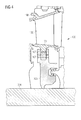
- Fig. 4 illustrates a schematical view of the guide vane device 100 as shown in Fig. 3 , wherein the diaphragm 303 is shown in more detail.
- the diaphragm 303 comprises a bracket-like shape and is clamped to the mounting section 107 of the rail 103.
- the diaphragm 303 comprises a sealing lip for sealing purposes.
- Fig. 4 illustrates the aerofoil 102 that is formed between the outer platform 108 and the inner platform 101.
Landscapes
- Engineering & Computer Science (AREA)
- Mechanical Engineering (AREA)
- General Engineering & Computer Science (AREA)
- Turbine Rotor Nozzle Sealing (AREA)
Priority Applications (6)
| Application Number | Priority Date | Filing Date | Title |
|---|---|---|---|
| EP10161435A EP2383435A1 (de) | 2010-04-29 | 2010-04-29 | Hohle Innenführung einer Turbinenschaufel |
| RU2012151011/06A RU2576600C2 (ru) | 2010-04-29 | 2011-03-30 | Устройство направляющих лопаток для турбины и способ его изготовления |
| CN201180021488.0A CN102906374B (zh) | 2010-04-29 | 2011-03-30 | 用于涡轮机的导流风标装置及其生产方法 |
| EP11711875.2A EP2534340B1 (de) | 2010-04-29 | 2011-03-30 | Hohle Innenführung einer Turbinenschaufel |
| US13/642,881 US9869200B2 (en) | 2010-04-29 | 2011-03-30 | Turbine vane hollow inner rail |
| PCT/EP2011/054931 WO2011134731A1 (en) | 2010-04-29 | 2011-03-30 | Turbine vane hollow inner rail |
Applications Claiming Priority (1)
| Application Number | Priority Date | Filing Date | Title |
|---|---|---|---|
| EP10161435A EP2383435A1 (de) | 2010-04-29 | 2010-04-29 | Hohle Innenführung einer Turbinenschaufel |
Publications (1)
| Publication Number | Publication Date |
|---|---|
| EP2383435A1 true EP2383435A1 (de) | 2011-11-02 |
Family
ID=43032977
Family Applications (2)
| Application Number | Title | Priority Date | Filing Date |
|---|---|---|---|
| EP10161435A Withdrawn EP2383435A1 (de) | 2010-04-29 | 2010-04-29 | Hohle Innenführung einer Turbinenschaufel |
| EP11711875.2A Not-in-force EP2534340B1 (de) | 2010-04-29 | 2011-03-30 | Hohle Innenführung einer Turbinenschaufel |
Family Applications After (1)
| Application Number | Title | Priority Date | Filing Date |
|---|---|---|---|
| EP11711875.2A Not-in-force EP2534340B1 (de) | 2010-04-29 | 2011-03-30 | Hohle Innenführung einer Turbinenschaufel |
Country Status (5)
| Country | Link |
|---|---|
| US (1) | US9869200B2 (de) |
| EP (2) | EP2383435A1 (de) |
| CN (1) | CN102906374B (de) |
| RU (1) | RU2576600C2 (de) |
| WO (1) | WO2011134731A1 (de) |
Cited By (4)
| Publication number | Priority date | Publication date | Assignee | Title |
|---|---|---|---|---|
| FR3001493A1 (fr) * | 2013-01-29 | 2014-08-01 | Snecma | Aubage fixe de distribution de flux a platine d'etancheite integree |
| EP3015657A1 (de) * | 2014-10-31 | 2016-05-04 | Siemens Aktiengesellschaft | Gasturbinenleitschaufelsegment |
| EP3730742A1 (de) * | 2019-04-24 | 2020-10-28 | Raytheon Technologies Corporation | Leitschaufelkernanordnung und verfahren |
| CN116428019A (zh) * | 2023-05-30 | 2023-07-14 | 东方电气集团东方汽轮机有限公司 | 一种燃气轮机透平喷嘴密封结构 |
Families Citing this family (11)
| Publication number | Priority date | Publication date | Assignee | Title |
|---|---|---|---|---|
| KR20150074625A (ko) * | 2013-12-24 | 2015-07-02 | 삼성테크윈 주식회사 | 압축 장치 코어용 지지대 및 이를 구비한 압축 장치 모듈 |
| US10012106B2 (en) * | 2014-04-03 | 2018-07-03 | United Technologies Corporation | Enclosed baffle for a turbine engine component |
| JP5717904B1 (ja) * | 2014-08-04 | 2015-05-13 | 三菱日立パワーシステムズ株式会社 | 静翼、ガスタービン、分割環、静翼の改造方法、および、分割環の改造方法 |
| EP3034798B1 (de) * | 2014-12-18 | 2018-03-07 | Ansaldo Energia Switzerland AG | Gasturbinenschaufel |
| DE102016202519A1 (de) * | 2016-02-18 | 2017-08-24 | MTU Aero Engines AG | Leitschaufelsegment für eine Strömungsmaschine |
| KR101937586B1 (ko) * | 2017-09-12 | 2019-01-10 | 두산중공업 주식회사 | 베인 조립체, 터빈 및 이를 포함하는 가스터빈 |
| CN116057255A (zh) * | 2020-09-04 | 2023-05-02 | 西门子能源全球两合公司 | 燃气涡轮发动机中的导向轮叶 |
| US11674400B2 (en) * | 2021-03-12 | 2023-06-13 | Ge Avio S.R.L. | Gas turbine engine nozzles |
| US12091982B2 (en) | 2022-06-10 | 2024-09-17 | Ge Infrastructure Technology Llc | Turbine component with heated structure to reduce thermal stress |
| US12129771B1 (en) * | 2023-08-22 | 2024-10-29 | Ge Infrastructure Technology Llc | Stator vane assembly having mechanical retention device |
| US12449128B1 (en) | 2024-11-27 | 2025-10-21 | Ge Vernova Infrastructure Technology Llc | Boss for a fuel injection assembly having cooling circuit and combustor provided therewith |
Citations (8)
| Publication number | Priority date | Publication date | Assignee | Title |
|---|---|---|---|---|
| GB938247A (en) * | 1962-03-26 | 1963-10-02 | Rolls Royce | Gas turbine engine having cooled turbine blading |
| US3829233A (en) | 1973-06-27 | 1974-08-13 | Westinghouse Electric Corp | Turbine diaphragm seal structure |
| US4126405A (en) | 1976-12-16 | 1978-11-21 | General Electric Company | Turbine nozzle |
| US4930980A (en) * | 1989-02-15 | 1990-06-05 | Westinghouse Electric Corp. | Cooled turbine vane |
| US5114159A (en) * | 1991-08-05 | 1992-05-19 | United Technologies Corporation | Brush seal and damper |
| EP1045114A2 (de) * | 1999-04-15 | 2000-10-18 | General Electric Company | Versorgungsrohransatz für die Kühlung der dritten Stufe einer Gasturbinenlaufschaufel |
| US20060013685A1 (en) * | 2004-07-14 | 2006-01-19 | Ellis Charles A | Vane platform rail configuration for reduced airfoil stress |
| EP1793088A2 (de) | 2005-11-30 | 2007-06-06 | General Electric Company | Verfahren und Vorrichtung zur Montierung von Gasturbinenleitschaufeln . |
Family Cites Families (6)
| Publication number | Priority date | Publication date | Assignee | Title |
|---|---|---|---|---|
| US3700348A (en) * | 1968-08-13 | 1972-10-24 | Gen Electric | Turbomachinery blade structure |
| JP3416447B2 (ja) * | 1997-03-11 | 2003-06-16 | 三菱重工業株式会社 | ガスタービンの翼冷却空気供給システム |
| ITMI991208A1 (it) * | 1999-05-31 | 2000-12-01 | Nuovo Pignone Spa | Dispositivo per il posizionamento di ugelli di uno stadio statorico eper il raffreddamento di dischi rotorici in turbine a gas |
| US6439837B1 (en) * | 2000-06-27 | 2002-08-27 | General Electric Company | Nozzle braze backside cooling |
| GB2365079B (en) * | 2000-07-29 | 2004-09-22 | Rolls Royce Plc | Blade platform cooling |
| US6761529B2 (en) * | 2002-07-25 | 2004-07-13 | Mitshubishi Heavy Industries, Ltd. | Cooling structure of stationary blade, and gas turbine |
-
2010
- 2010-04-29 EP EP10161435A patent/EP2383435A1/de not_active Withdrawn
-
2011
- 2011-03-30 RU RU2012151011/06A patent/RU2576600C2/ru not_active IP Right Cessation
- 2011-03-30 WO PCT/EP2011/054931 patent/WO2011134731A1/en not_active Ceased
- 2011-03-30 EP EP11711875.2A patent/EP2534340B1/de not_active Not-in-force
- 2011-03-30 CN CN201180021488.0A patent/CN102906374B/zh not_active Expired - Fee Related
- 2011-03-30 US US13/642,881 patent/US9869200B2/en not_active Expired - Fee Related
Patent Citations (8)
| Publication number | Priority date | Publication date | Assignee | Title |
|---|---|---|---|---|
| GB938247A (en) * | 1962-03-26 | 1963-10-02 | Rolls Royce | Gas turbine engine having cooled turbine blading |
| US3829233A (en) | 1973-06-27 | 1974-08-13 | Westinghouse Electric Corp | Turbine diaphragm seal structure |
| US4126405A (en) | 1976-12-16 | 1978-11-21 | General Electric Company | Turbine nozzle |
| US4930980A (en) * | 1989-02-15 | 1990-06-05 | Westinghouse Electric Corp. | Cooled turbine vane |
| US5114159A (en) * | 1991-08-05 | 1992-05-19 | United Technologies Corporation | Brush seal and damper |
| EP1045114A2 (de) * | 1999-04-15 | 2000-10-18 | General Electric Company | Versorgungsrohransatz für die Kühlung der dritten Stufe einer Gasturbinenlaufschaufel |
| US20060013685A1 (en) * | 2004-07-14 | 2006-01-19 | Ellis Charles A | Vane platform rail configuration for reduced airfoil stress |
| EP1793088A2 (de) | 2005-11-30 | 2007-06-06 | General Electric Company | Verfahren und Vorrichtung zur Montierung von Gasturbinenleitschaufeln . |
Cited By (8)
| Publication number | Priority date | Publication date | Assignee | Title |
|---|---|---|---|---|
| FR3001493A1 (fr) * | 2013-01-29 | 2014-08-01 | Snecma | Aubage fixe de distribution de flux a platine d'etancheite integree |
| EP3015657A1 (de) * | 2014-10-31 | 2016-05-04 | Siemens Aktiengesellschaft | Gasturbinenleitschaufelsegment |
| EP3730742A1 (de) * | 2019-04-24 | 2020-10-28 | Raytheon Technologies Corporation | Leitschaufelkernanordnung und verfahren |
| US20200340362A1 (en) * | 2019-04-24 | 2020-10-29 | United Technologies Corporation | Vane core assemblies and methods |
| US11021966B2 (en) * | 2019-04-24 | 2021-06-01 | Raytheon Technologies Corporation | Vane core assemblies and methods |
| US11828193B2 (en) | 2019-04-24 | 2023-11-28 | Rtx Corporation | Vane core assemblies and methods |
| CN116428019A (zh) * | 2023-05-30 | 2023-07-14 | 东方电气集团东方汽轮机有限公司 | 一种燃气轮机透平喷嘴密封结构 |
| CN116428019B (zh) * | 2023-05-30 | 2025-09-02 | 东方电气集团东方汽轮机有限公司 | 一种燃气轮机透平喷嘴密封结构 |
Also Published As
| Publication number | Publication date |
|---|---|
| US9869200B2 (en) | 2018-01-16 |
| CN102906374B (zh) | 2016-04-13 |
| US20130202409A1 (en) | 2013-08-08 |
| RU2576600C2 (ru) | 2016-03-10 |
| RU2012151011A (ru) | 2014-06-10 |
| EP2534340A1 (de) | 2012-12-19 |
| CN102906374A (zh) | 2013-01-30 |
| EP2534340B1 (de) | 2017-05-31 |
| WO2011134731A1 (en) | 2011-11-03 |
Similar Documents
| Publication | Publication Date | Title |
|---|---|---|
| US9869200B2 (en) | Turbine vane hollow inner rail | |
| EP3121382B1 (de) | Gasturbinenmotoren mit kanalgekühlten haken zum halten eines teils relativ zu einer motorgehäusestruktur | |
| EP2093384B2 (de) | Filtersystem für eine Außendichtung einer Turbinenschaufel | |
| JP4785507B2 (ja) | ブルノーズ段部付きタービンノズル | |
| EP2553220B1 (de) | Leitschaufel mit gekühlter plattform für eine gasturbine | |
| CN103459778B (zh) | 包括热屏蔽的燃气轮机及操作方法 | |
| EP3039249B1 (de) | Mateface-oberflächen mit einer geometrie auf einer turbomaschinen-hardware | |
| EP2390466A1 (de) | Eine Kühlanordnung für eine Gasturbine | |
| EP2798156B1 (de) | Gasturbinenanordnung zur reduzierung von spannungen an turbinenscheiben und zugehörige gasturbine | |
| EP2715069B1 (de) | Kolbendichtungsring | |
| EP3163025B1 (de) | Turbinenschaufel mit auslassöffnung in deckband | |
| EP3294994B1 (de) | Gasturbinenleitschaufelsegment und verfahren zur herstellung | |
| EP3047111B1 (de) | Gasturbinentriebwerksbauteil, zugehöriges gasturbinentriebwerk und verfahren zum kühlen | |
| JP2012530870A (ja) | ターボ機械のための環状流路 | |
| EP2623719B1 (de) | Entspannungsschlitze für Turbinenschaufelring | |
| CN103620228B (zh) | 叶片平台下游容易适用的压缩机排放系统 | |
| EP2713009B1 (de) | Kühlverfahren und -system zur Kühlung von Schaufeln mindestens einer Schaufelreihe in einer drehenden Strömungsmaschine | |
| EP1748155B1 (de) | Gekühlte Mantelringanordnung einer Gasturbine sowie Verfahren zur Kühlung eines Mantelrings einer Gasturbine | |
| EP2530244B1 (de) | Ein Stator umliegend eines Rotors und Verfahren zur Kühlung | |
| EP3156595A1 (de) | Kanalisierungsrohr und verfahren zur herstellung eines kanalisierungsrohrs | |
| GB2564366A (en) | Air flow rectification assembly and turbomachine comprising an assembly of this type | |
| CN105593470B (zh) | 燃气涡轮机和安装方法 | |
| EP4553284A1 (de) | Turbinenmotor mit einer schaufelanordnung mit kühllöchern | |
| CN121666483A (zh) | 用于飞行器涡轮发动机的涡轮的引导轮叶组件 | |
| EP1790826A1 (de) | Leitschaufel für eine Turbine eines Wärmekraftwerks |
Legal Events
| Date | Code | Title | Description |
|---|---|---|---|
| AK | Designated contracting states |
Kind code of ref document: A1 Designated state(s): AT BE BG CH CY CZ DE DK EE ES FI FR GB GR HR HU IE IS IT LI LT LU LV MC MK MT NL NO PL PT RO SE SI SK SM TR |
|
| AX | Request for extension of the european patent |
Extension state: AL BA ME RS |
|
| PUAI | Public reference made under article 153(3) epc to a published international application that has entered the european phase |
Free format text: ORIGINAL CODE: 0009012 |
|
| STAA | Information on the status of an ep patent application or granted ep patent |
Free format text: STATUS: THE APPLICATION IS DEEMED TO BE WITHDRAWN |
|
| 18D | Application deemed to be withdrawn |
Effective date: 20120503 |