EP2383535B1 - Method and system for loading and unloading cartridges into/from a magazine for firearms - Google Patents
Method and system for loading and unloading cartridges into/from a magazine for firearms Download PDFInfo
- Publication number
- EP2383535B1 EP2383535B1 EP11163110.7A EP11163110A EP2383535B1 EP 2383535 B1 EP2383535 B1 EP 2383535B1 EP 11163110 A EP11163110 A EP 11163110A EP 2383535 B1 EP2383535 B1 EP 2383535B1
- Authority
- EP
- European Patent Office
- Prior art keywords
- breech
- chamber
- cartridge
- loading
- magazine
- Prior art date
- Legal status (The legal status is an assumption and is not a legal conclusion. Google has not performed a legal analysis and makes no representation as to the accuracy of the status listed.)
- Active
Links
Images


Classifications
-
- F—MECHANICAL ENGINEERING; LIGHTING; HEATING; WEAPONS; BLASTING
- F41—WEAPONS
- F41A—FUNCTIONAL FEATURES OR DETAILS COMMON TO BOTH SMALLARMS AND ORDNANCE, e.g. CANNONS; MOUNTINGS FOR SMALLARMS OR ORDNANCE
- F41A9/00—Feeding or loading of ammunition; Magazines; Guiding means for the extracting of cartridges
- F41A9/01—Feeding of unbelted ammunition
- F41A9/24—Feeding of unbelted ammunition using a movable magazine or clip as feeding element
- F41A9/26—Feeding of unbelted ammunition using a movable magazine or clip as feeding element using a revolving drum magazine
-
- F—MECHANICAL ENGINEERING; LIGHTING; HEATING; WEAPONS; BLASTING
- F41—WEAPONS
- F41A—FUNCTIONAL FEATURES OR DETAILS COMMON TO BOTH SMALLARMS AND ORDNANCE, e.g. CANNONS; MOUNTINGS FOR SMALLARMS OR ORDNANCE
- F41A9/00—Feeding or loading of ammunition; Magazines; Guiding means for the extracting of cartridges
- F41A9/38—Loading arrangements, i.e. for bringing the ammunition into the firing position
- F41A9/39—Ramming arrangements
- F41A9/42—Rammers separate from breech-block
-
- F—MECHANICAL ENGINEERING; LIGHTING; HEATING; WEAPONS; BLASTING
- F41—WEAPONS
- F41A—FUNCTIONAL FEATURES OR DETAILS COMMON TO BOTH SMALLARMS AND ORDNANCE, e.g. CANNONS; MOUNTINGS FOR SMALLARMS OR ORDNANCE
- F41A9/00—Feeding or loading of ammunition; Magazines; Guiding means for the extracting of cartridges
- F41A9/61—Magazines
- F41A9/64—Magazines for unbelted ammunition
- F41A9/73—Drum magazines
Definitions
- the present invention relates to a method for loading and unloading cartridges inside the magazine of a firearm.
- Such magazine is for example of the cylinder type of a drum, to be applied on firearms placed either on military means, or on fixed positions.
- Magazines are known, like the magazines of the Revolver guns, in which the cartridges are charged in a circular cylinder made by a plurality of chambers or seats where the cartridges are inserted.
- the cylinder, and in particular the various chambers are fixed and the cartridge is triggered directly in the chamber, either making the function of the chamber coincide with that of the breech, or, through suitable systems and mechanisms, the cartridge is pushed by such chambers in a breech where it is subsequently triggered.
- a further technical solution known to a person skilled in the art consists in deflagrating the cartridge in a breech separated from the cylinder, by inserting a pushing mechanism of the cartridge from the chamber to the breech.
- a tank gun with a breech and separate rotating drum magazine is for example disclosed in DE 41 23 338 A1 , which represents the starting point of the present invention.
- a further problem of the cylinder magazines of the known art is the extraction of the shells from the cylinder itself in order to permit the charging of new cartridges.
- Such phase has the same problems seen in the aforementioned case for the charging of the cartridge inside the breech as it is necessary to provide for a mechanism which frees the chambers from the shells.
- the firearms mainly those of great dimensions, are equipped with a locking mechanism for the cartridges inside the chambers, in order to prevent them sticking out of their own chamber during the charging, the rotation or the positioning of the cannon with the raising required.
- the present invention aims to obviate such drawbacks by proposing a loading and unloading system and a loading and unloading method of the cartridges, adapted to optimize the time intervals, which introduces a pre-charging phase of the cartridge which anticipates the phase in which the cartridge is inserted in the breech.
- Such method furthermore permits the automatic execution of various phases at the same time, so increasing the firing rate.
- the increase of the firing rate is possible thanks to an electronic control system which monitors and actuates the various mechanisms in a fast and safe way.
- a peculiarity of such method is the mobility of the chambers of the cylinder compared to the cylinder itself, which remains in a fixed position with respect to the cradle; furthermore, the recoil is positively exploited to which the breech undergoes during the deflagration of the cartridge in order to catch and approach the suitable chamber to the cradle so speeding up the next charging phase.
- the recoil force is also used for the extraction of the empty shell case from the breech, by exploiting the kinetic energy associated to the shell during recoil.
- An aspect of the present invention relates to a loading and unloading system of cartridges and shells in a magazine for firearms having the characteristics of the annexed claim 1.
- a further aspect of the present invention relates to a loading and unloading method of cartridges and shells in a magazine for firearms having the characteristics of the annexed claim 10.
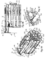
- the loading system comprises a box-like structure 109 inside which a plurality of chambers 21 are present, adapted to house the cartridges or shells, for example wrapped on a cylinder 2, a moving mechanism 3 of the chambers, a chamber catching mechanism 4 and a breech block 10, adapted to facilitate the loading of the cartridge.
- the system further comprises at least one cam mechanism 5 for disengaging a retaining lever 23 of the cartridge , a pre-loading mechanism 6 in order to permit the movement of chambers 21 towards the breech block 10, a charging mechanism 7 for inserting the cartridge in a breech block 10, a deceleration mechanism 8 of the shell adapted to slow such shell once extracted from the fire chamber and an extraction mechanism 9 of the shell for freeing the chamber from the shell and permitting the insertion in the cylinder magazine 2 of a new cartridge.
- the chambers are sequentially movable with respect to the breech, in order to present themselves one by one in the position in which charging mechanism 7 inserts the cartridge in the breech.
- each chamber On cylinder 2 chambers 21 are placed, each chamber being movable and sliding, preferably on a rail 22, for example fixed to cylinder 2 itself, by a guide placed in the lower portion of such chamber 21.
- the movement of such chamber 21 is longitudinal with respect to the axis X of the breech.
- the number of rails 22 and guides can increase in order to better assure the movement of chamber 21.
- Such chambers 21 sliding on rails 22 are equipped with a retaining device adapted to maintain chamber 21 always at the end of the stroke on cylinder 2.
- Rail 22 is fastened preferably by bolts or equivalent systems, on cylinder 2 whereas the guides placed on chamber 21 can be directly integrated in the structure of chamber 21 or connected by means of welds or bolts or equivalent systems.
- At least one retaining lever 23 of the cartridges is placed, suitably pivoted which rotates from the inside to the outside of the chamber and vice versa, thanks to at least one slot 216.
- the pivoting of retaining lever 23 occurs at a pair of preferably triangular protrusions 231A and 231B, placed on chamber 21 between which said lever 23 is placed.
- Said protrusions 231A and 231B can be either directly created with the construction of chamber 21 or afterwards fixed with suitable fixing systems.
- the shape of said protrusions 231A and 231B can vary in order to facilitate their fixing according to the chosen method.
- At least one slot 215 is further present, placed on the side of chamber 21, where a portion of the deceleration mechanism 8 is placed.
- Position one defines chamber 21 being aligned with breech block 10, the numbering progressing in the clockwise direction up to position twelve.
- Chamber 21 being in position twelve is the one interested to the preloading phase of the cartridge.
- chamber 21 is at position one when it will be aligned with breech block 10, whereas cylinder 21 will be in position n when the preloading phase of the cartridge will be made.
- Chambers 21 have preferably a cylindrical hollow shape, having a front mouth 217A towards breech block 10 and a rear one 217B towards the outside of the system. The dimensions of the chambers depend on the calibre of the cartridge which is used in such firearm.
- the material with which cylinder 2, chambers 21 and the above cited structures are made, is preferably metal but it is possible for example to create chambers 21 of different materials as for example of reinforced plastics or equivalent materials.
- each single chamber 21 at least one slot 212 is present, which covers at least one portion of said chamber 21 up to rear mouth 217B, adapted to permit to charging mechanism 7 to push the cartridge in block 10.
- an actuation plate 213 is present, made of metal or equivalent materials, suitably fixed to chamber 21, preferably by means of a welding or bolts or equivalent systems, which cooperates with pre-loading mechanism 6, in order to permit its function.
- Said plate 213 in an embodiment can be directly realized together with chamber 21.
- a hooking portion 2142 is associated, having a trapezoidal section adapted to engage with hooking mechanism 4, in order to bind the chamber itself to breech block 10.
- Cylinder 2 rotates around its own longitudinal axis, thanks to moving mechanism 3, comprising a wheel 31, connected with the central body of cylinder 2 by means of a pin 312, a locking peg 32 and a group of actuators 33 adapted to generate the rotation.
- Said wheel 31 has a number of equally spaced holes 311, corresponding to the number of chambers 21 present on the cylinder 2.
- Said holes 311 are penetrated by locking peg 32 which stops in this way the rotation of cylinder 2 in the various positions by assuring that it does not move from such seat during the recoil or other critical phases of the method.
- Said peg 32 furthermore when suitably controlled raises coming out of hole 311, in which it was inserted, so permitting the rotation of the cylinder.
- the rotation of cylinder 2 is generated by the group of actuators 33 preferably comprising at least two guide handles 331A and 331B substantially disposed on the circumference of the cylinder and which are bound to it by means of a pin 333.
- the handles then are respectively connected with at least two actuators 332A and 332B.
- the number of handles and actuators can vary according to the dimensions of the cylinder and the safety level which such system can reach.
- Actuators 332A and 332B are preferably realized with pistons or equivalent systems, they are vertically positioned in this embodiment and in opposition, in function of the rotation direction of cylinder 2.
- peg 333 is inserted, by means of suitable control systems, in the suitable hole 311 in which the handle is positioned; thereafter actuators 332A and 332B stretch themselves in order to guarantee a couple of forces which, through handles 331A and 331B, gets the cylinder 2 to rotate.
- Breech block 10 comprises a breech or firing chamber 101 where the cartridge is made to explode, a mouth portion 102, comprising a preferably metal structure with a through hole, a transit chamber 104 adapted to make the cartridge transit, a shutter 103 and a barrel 105.
- Said block 10 can move along the direction of breech 101 during the recoil caused by the deflagration of the cartridge.
- Said aforementioned structures are preferably made of metal material or of equivalent material adapted to withstand the deflagration of the cartridge.
- Said breech block 10 can vary in shape, dimensions and number of parts according to the firing device used, so that it must not be considered limitative.
- Charging mechanism 7 is placed above chamber 21 being in the position one and is integrally associated with breech 101 and comprises a pushing actuator 71, for example a hydraulic piston interposed between the breech and a sled 72, for example realized with the shape of a U positioned over such chamber 21, adapted to move in the direction of the breech for a predetermined distance. Said sled moves on guides 721A and 721B, which slide on two tracks 73A and 73B.
- a pushing actuator 71 for example a hydraulic piston interposed between the breech and a sled 72, for example realized with the shape of a U positioned over such chamber 21, adapted to move in the direction of the breech for a predetermined distance.
- Said sled moves on guides 721A and 721B, which slide on two tracks 73A and 73B.
- Tracks 73A and 73B preferably have a rectangular cross-section with holes. Said tracks in turn slide on a U-shaped bar 74 connected with the base with the portion of mouth 102 of the breech block 10. Said bar 74 has a step 742 in both arms 741A and 741B at a distance equal to the recoil of breech block 10 , so that tracks 73A and 73B can slide on the same in order that sled 72 moves for a predetermined distance so to permit the charging of the cartridge and the return of the shell after the shooting, as the aforementioned step has an end-of-stroke function for tracks 73A and 73B.
- tracks 73 and of arms 741 can vary from the one described, as their task is to assure the longitudinal movement of mechanism 7, for example by creating tracks 73 with a triangular shape and arms 741 with a shape complementary to that of tracks 73 for permitting and assuring the movement.
- At least one portion 722 of the push is present, adapted to push the cartridge placed in chamber 21 inside breech block 10 by virtue of the movement generated by such actuator.
- Said portion 722 of the push preferably has a triangular section as seen in projection. Portion 722 of the push slides inside slot 212 of chamber 21 by pressing on the bottom of the cartridge. Said portion 722 is geared to bar 72 through pin 723 which permits to pushing point 722 to rotate, as during the rotation of cylinder 2 such pushing points 722 must be raised so permitting the rotation, then being lowered just before charging mechanism 7 is actuated.
- Pre-loading mechanism 6 comprises a pre-loading actuator 61 which, preferably acting on plate 213 placed on chamber 21, permits to the same to advance for a quantity sufficient to engage hooking mechanism 4, preferably during the recoil of block 10 thanks to hooking portion 2142.
- the advancing movement of the chamber in the pre-loading position occurs at the same time with the recoil movement of the breech block.
- Actuator 61 is preferably provided with a piston placed on the position preceding the one in which the cartridge is inserted into the breech, in order to permit the rotation of cylinder 2.
- Hooking mechanism 4 of the chamber comprises a shaped hooking plate 41 connected with mouth 102 of breech block 10.
- Said plate 41 has the shape of a section of a crown of circumference comprising a through hole 411 adapted to make the cartridge transit from chamber 21 to breech 101 in the loading phase of the cartridge.
- Said plate 41 can advantageously be directly integrated with breech block 10.
- Hooking mechanism 4 also comprises a housing 42 for example U-shaped, placed on the edge of plate 41, in which a mobile hooking plate 43 is geared, preferably having an L-shaped cross-section, which can partially rotate around the axis of pins 421.
- portion 42 depends on the rotation of the cylinder which in the case described is of clockwise type.
- Said mechanism 4 is actuated on chamber 21 being at position twelve, so in the position preceding the one in which the cartridge is inserted in the breech.
- Plate 43 rotates by raising when the chamber approaches breech block 10, pushed by the actuator of the preloading mechanism, until hooking portion 2142 placed on chamber 21 overcomes such plate 43 which can again descend so blocking chamber 21 in a position proximate to mouth portion 102 of block 10.
- pre-loading mechanism 6 It is possible to implement a control to pre-loading mechanism 6, so that it can engage chamber 21 at position twelve to hooking mechanism 4 without the occurrence of the recoil of breech block 10, for example in order to pre-load the first cartridge in the shooting session in which no cartridge is yet present inside breech 101.
- cam mechanism 5 is activated comprising a cam 51, formed by a circular portion 511 with a reduced curvature angle with respect to that of shaped plate 41, and at least one guide placed externally with respect to circular portion 511 in which hooking portion 2142 is inserted, which in this way is not subject to the movement of the cam, so always guaranteeing the engagement of chamber 21 itself with breech block 10.
- Said cam 51 is adapted to disengage from the retaining lever of cartridge 23.
- Said cam 51 during the rotation of cylinder 2 raises lever 23, by making it come out of the profile of chamber 21 by means of provided slot 216.
- Cam 51 can be realized in various shapes adapted to guarantee the raising of lever 23 during the rotation of cylinder 2.
- the guide can be realized by bending the edges of plate 41 in order to generate a ditch able to make hooking portion 2142 slide without generating clearances among the parts and to avoid the release of chamber 21 during the recoil, which chamber 21 thanks to track 22 slides following the movement of breech block 10.
- block 10 recoils, and such force as well as contribute to the hooking of chamber 21, at position twelve, as seen before, is used for the extraction of the shell from breech 101.
- shutter 103 is opened so permitting the automatic exit of the shell from breech 101, as the same shell has a kinetic energy generated by the recoil force.
- the shell when exiting from breech 101 is guided by means of transit chamber 104 towards the empty chamber 21 being at position one.
- Said deceleration mechanism 8 is adapted to slow the speed of the shell and avoid that it can damage portions of the structure of the magazine, and comprises a contact portion 81, a device with levers 82, a dampener 83 and a block portion 84.
- the shell is definitely blocked in its progression from block portion 84, placed in the end portion of chamber 21.
- Said portion 84 having a preferably triangular shape seen in projection, is fixed by means of pin 841 to the structure of chamber 21 and through suitable spring devices and is adapted to permit the introduction of new cartridges inside the empty chambers 21 being able to lower itself by rotating, but it does not permit the exit of the cartridge or shell from rear mouth 217B of chamber 21 thanks to a step.
- dampener 83 is a piston placed on the external surface of chamber 21, whereas contact portion 81 is placed inside chamber 21.
- Chamber 21 in a loading and unloading position of the shell, once having received the shell, is still engaged to breech block 10; in the subsequent rotation which brings it to position two, it is pushed in the subsequent chamber 21 which in turn moves from position twelve to position one.
- the shell remains inside chamber 21 preferably until said chamber 21 goes over to position 4 from position three.
- Such mechanism comprises an expulsion plate 91 and a pushing device 92.
- Plate 91 comprises a through hole, adapted to transit the shell and a least one cam 912, adapted to raise the locking lever of cartridges 23 during the rotation in which chamber 21 moves from position three to position four.
- lever 23 permits the subsequent expulsion phase of the shell by pushing device 92.
- Said pushing device 92 is implemented in the same way with which charging mechanism 7 described before has been realized.
- Said device 92 comprises an actuator which is fixed to a U-shaped structure 922 on which guides 923A and 923B are placed, which slide along two tracks 924A and 924B.
- Tracks 924A and 924B have a rectangular cross-section and are provided with holes.
- At least one pushing point is present (non shown in the figure), adapted to push the shell placed in chamber 21 at the outside of the cylinder structure 2, like it occurs for loading the cartridge in the breech.
- actuator 925 which is implemented with a piston. During the rotation such pushing points are raised so permitting the rotation of cylinder 2 and thereafter they are lowered just before the expulsion mechanism of the shell 9 is actuated.
- Said mechanism 9 is placed at such a height from cylinder 2 to permit the rotation but also to permit to the pushing points to move the shell outside of chamber 21.
- Said pushing device 92 is sustained by a U-shaped bar (not shown in the figure) fixed at the base to external structure 109. On the arms of the U-shaped bar tracks 924A and 924B of such system slide.
- the method comprises the following phases: insertion of cartridges in the suitable chambers 21 of the cylinder magazine 2; pre-loading of the cartridge contained in chamber 21 placed at position n; rotation of cylinder 2; loading of the cartridge in breech 101; extraction of the shell from breech 101; displacement of chamber 21; unloading of the shell from the magazine; new loading of the chambers with new cartridges.
- the insertion of the cartridges inside chambers 21 can occur in a sequential way for example by inserting the cartridges in the various chambers 21 being for example at position five, or at the same time in a predetermined number of chambers at the same time.
- the pre-loading phase of the cartridges contained in chamber 21 placed at position n consists in hooking to breech block 10 of chamber 21, in a movable way through hooking mechanism 4 thanks to the combined action of the recoil of breech block 10 and of pre-loading mechanism 6.
- the extraction phase of the shell from breech 101 is entered.
- Such phase consists in the extraction of the shell from mouth 102 during the recoil of breech block 10.
- the shutter is opened and the shell with a certain kinetic energy during the maximum recoil comes out the breech and enters again in chamber 21 of position one remained empty, as such chamber is still hooked to breech block 10.
- Chamber 21 during the recoil follows the motion of the breech block, thanks to track 22.
- Such kinetic energy of the shell is dampened by a deceleration mechanism 8 placed in chambers 21 able to slow down such shell at the entry in the chamber.
- phase is the unloading of the shell from the magazine.
- Such phase begins in chamber 21 to the inside of which a shell preferably reaches position three.
- an expulsion mechanism is present which disables retaining lever 23 during the rotation from phase three to four, thanks to a cam 912 and finally when chamber 21 has reached position four an actuator 921 is activated, which pushes out the shell passing through the holed plate and recovered by a displacement system of the shell.
- the pitch of the cylinder is managed thanks to an electronic controller which governs rotary mechanism 3 on the base of signals coming from other mechanisms at play.
- Another controller is present, also electronic which acts on the possibility of the cannon to shoot the cartridge which also receives signals from the other mechanisms cited before.
- Such integrated mechanism in a suitable tracking system can follow the firearm during the movements for the tracking, so permitting to reach elevation angles from 0° to 75° in the described embodiment.
Landscapes
- Engineering & Computer Science (AREA)
- General Engineering & Computer Science (AREA)
- Portable Nailing Machines And Staplers (AREA)
- Toys (AREA)
- Aiming, Guidance, Guns With A Light Source, Armor, Camouflage, And Targets (AREA)
- Information Transfer Between Computers (AREA)
- Warehouses Or Storage Devices (AREA)
Priority Applications (1)
| Application Number | Priority Date | Filing Date | Title |
|---|---|---|---|
| PL11163110T PL2383535T3 (pl) | 2010-04-27 | 2011-04-20 | Sposób i system do załadowania i wyładowania nabojów do/z magazynka dla broni palnej |
Applications Claiming Priority (1)
| Application Number | Priority Date | Filing Date | Title |
|---|---|---|---|
| ITTO2010A000352A IT1399814B1 (it) | 2010-04-27 | 2010-04-27 | Metodo e sistema di caricamento e scaricamento di proiettili in un caricatore per armi da fuoco. |
Publications (2)
| Publication Number | Publication Date |
|---|---|
| EP2383535A1 EP2383535A1 (en) | 2011-11-02 |
| EP2383535B1 true EP2383535B1 (en) | 2014-11-26 |
Family
ID=43250918
Family Applications (1)
| Application Number | Title | Priority Date | Filing Date |
|---|---|---|---|
| EP11163110.7A Active EP2383535B1 (en) | 2010-04-27 | 2011-04-20 | Method and system for loading and unloading cartridges into/from a magazine for firearms |
Country Status (7)
| Country | Link |
|---|---|
| US (1) | US8549978B2 (it) |
| EP (1) | EP2383535B1 (it) |
| JP (1) | JP5953006B2 (it) |
| CA (1) | CA2738393C (it) |
| ES (1) | ES2531130T3 (it) |
| IT (1) | IT1399814B1 (it) |
| PL (1) | PL2383535T3 (it) |
Families Citing this family (13)
| Publication number | Priority date | Publication date | Assignee | Title |
|---|---|---|---|---|
| IT1400435B1 (it) * | 2010-06-04 | 2013-05-31 | Oto Melara Spa | Elevatore per munizioni. |
| RU2533947C2 (ru) * | 2012-09-06 | 2014-11-27 | Открытое акционерное общество "Машиностроительный завод "Арсенал" (ОАО "МЗ "Арсенал") | Артиллерийская корабельная установка |
| US8875433B2 (en) * | 2012-10-20 | 2014-11-04 | Christopher V. Beckman | Firearm loading techniques eliminating firing pause and enabling rapid partial source replacement and load supplementation prior to empty |
| SE537591C2 (sv) * | 2013-11-07 | 2015-07-07 | Bae Systems Bofors Ab | Ammunitionshanteringssystem och metod för sortering av blandade ammunitionstyper i ett magasin |
| RU2607700C2 (ru) * | 2014-12-31 | 2017-01-10 | Открытое акционерное общество "Машиностроительный завод "Арсенал" (ОАО "МЗ "Арсенал") | Магазин корабельной артиллерийской установки |
| RU2587383C1 (ru) * | 2015-02-05 | 2016-06-20 | Открытое акционерное общество "Машиностроительный завод "Арсенал" (ОАО "МЗ "Арсенал") | Опорно-сцепной узел механического привода корабельной артиллерийской установки |
| US9671205B1 (en) * | 2016-08-09 | 2017-06-06 | Ho-Sheng Wei | Portable bullet receiving device |
| RU2651956C2 (ru) * | 2016-10-18 | 2018-04-24 | Российская Федерация, от имени которой выступает Министерство обороны Российской Федерации | Устройство для заряжания артиллерийского орудия |
| RU2694357C2 (ru) * | 2017-03-16 | 2019-07-11 | Евгений Евстафьевич Батиевский | Автоматический миномет |
| FR3078396B1 (fr) * | 2018-02-23 | 2020-02-14 | Nexter Systems | Dispositif de rechargement et tourelle comportant un tel dispositif |
| CN111928727B (zh) * | 2019-05-13 | 2022-06-21 | 南京理工大学 | 一种拨弹精准的迫击炮回转弹仓及其拨弹方法 |
| RU2754236C1 (ru) * | 2020-08-11 | 2021-08-30 | Открытое акционерное общество "Машиностроительный завод "АРСЕНАЛ" | Магазин боеприпасов корабельной артиллерийской установки |
| FR3136842B1 (fr) * | 2022-06-17 | 2026-04-10 | Nexter Systems | Arme de gros calibre a ensemble culasse a chambres multiples |
Family Cites Families (27)
| Publication number | Priority date | Publication date | Assignee | Title |
|---|---|---|---|---|
| GB134826A (it) * | 1918-11-04 | |||
| US2389162A (en) * | 1942-08-21 | 1945-11-20 | Jr Colin Mcinnes | Multiple signal discharger |
| US2790353A (en) * | 1951-11-29 | 1957-04-30 | John R Bird | Feeding mechanism for a firearm |
| US2933981A (en) * | 1953-10-26 | 1960-04-26 | Paul E Anderson | Automatic repeating rocket launcher |
| US3173334A (en) * | 1958-10-22 | 1965-03-16 | Landstrom Sven | Missile launching system |
| US3249011A (en) * | 1962-12-31 | 1966-05-03 | Palmer G Wermager | Missile tray with clamp |
| US3376785A (en) * | 1965-06-30 | 1968-04-09 | Bofors Ab | Installation for loading the launching tubes of a depth-charge launcher |
| US3598016A (en) * | 1969-03-18 | 1971-08-10 | Gen Electric | Automatic burst firing gun having revolving chambers |
| US3625107A (en) * | 1969-11-03 | 1971-12-07 | Us Army | Feed mechanism for an open breech high rate automatic rocket launcher |
| US3688637A (en) * | 1970-03-10 | 1972-09-05 | Gen Electric | Multibarrel automatic weapon |
| GB2004037B (en) * | 1977-09-10 | 1982-03-24 | Rheinmetall Gmbh | Mortar |
| US4457209A (en) * | 1980-08-27 | 1984-07-03 | Fmc Corporation | Automated large caliber ammunition handling system |
| EP0051119B1 (en) * | 1980-08-27 | 1985-02-06 | Fmc Corporation | Automatic large caliber ammunition loading system |
| US4640182A (en) * | 1983-11-04 | 1987-02-03 | Ares, Inc. | Shell feeding apparatus for guns |
| US4777863A (en) * | 1983-11-04 | 1988-10-18 | Ares, Inc. | Shell feeding apparatus for guns |
| US4671164A (en) * | 1985-05-03 | 1987-06-09 | Ares, Inc. | Shell magazine for tanks |
| DE3913173C2 (de) * | 1989-04-21 | 1995-02-16 | Krauss Maffei Ag | Trommelmagazin für die Munition einer großkalibrigen Waffe |
| EP0422401B1 (de) * | 1989-10-13 | 1994-01-05 | Oerlikon-Contraves AG | Waffengehäuse für eine Feuerwaffe |
| FR2668253B1 (fr) * | 1990-10-17 | 1994-09-30 | Creusot Loire | Dispositif d'identification et de controle de munition d'une arme a feu a chargement automatique et procede pour sa mise en óoeuvre. |
| US5131316A (en) * | 1991-07-12 | 1992-07-21 | General Electric Company | Autoloading apparatus for tank cannon |
| DE4123338A1 (de) * | 1991-07-15 | 1993-01-28 | Wegmann & Co | Kampfpanzerturm |
| SE9201433L (sv) * | 1992-05-06 | 1993-11-07 | Bofors Ab | Ansättare |
| FR2765958B1 (fr) * | 1997-07-11 | 1999-09-24 | Tda Armements Sas | Systeme de chargement d'un mortier et mortier equipe d'un tel systeme |
| DE59903630D1 (de) * | 1998-08-24 | 2003-01-16 | Contraves Ag | Verfahren und Vorrichtung zur Munitionszuführung bei Revolverkanonen |
| US6637310B2 (en) * | 2001-03-01 | 2003-10-28 | United Defense L.P. | Rotatable breech gun |
| AUPR895301A0 (en) * | 2001-11-19 | 2002-01-24 | Metal Storm Limited | Gun |
| US7311032B2 (en) * | 2002-09-04 | 2007-12-25 | Heckler & Koch, Gmbh | Firearms with gas pressure loading mechanisms |
-
2010
- 2010-04-27 IT ITTO2010A000352A patent/IT1399814B1/it active
-
2011
- 2011-04-20 ES ES11163110T patent/ES2531130T3/es active Active
- 2011-04-20 PL PL11163110T patent/PL2383535T3/pl unknown
- 2011-04-20 EP EP11163110.7A patent/EP2383535B1/en active Active
- 2011-04-21 CA CA2738393A patent/CA2738393C/en active Active
- 2011-04-22 JP JP2011096281A patent/JP5953006B2/ja active Active
- 2011-04-26 US US13/094,567 patent/US8549978B2/en active Active
Also Published As
| Publication number | Publication date |
|---|---|
| US20110258898A1 (en) | 2011-10-27 |
| PL2383535T3 (pl) | 2015-07-31 |
| JP5953006B2 (ja) | 2016-07-13 |
| CA2738393C (en) | 2017-10-24 |
| ES2531130T3 (es) | 2015-03-11 |
| JP2011232024A (ja) | 2011-11-17 |
| CA2738393A1 (en) | 2011-10-27 |
| EP2383535A1 (en) | 2011-11-02 |
| ITTO20100352A1 (it) | 2011-10-28 |
| US8549978B2 (en) | 2013-10-08 |
| IT1399814B1 (it) | 2013-05-03 |
Similar Documents
| Publication | Publication Date | Title |
|---|---|---|
| EP2383535B1 (en) | Method and system for loading and unloading cartridges into/from a magazine for firearms | |
| US9702649B1 (en) | Reciprocally-cycled weapon | |
| EP2356396B1 (en) | Externally-actuated weapon | |
| EP1102022B1 (en) | Automatic weapon with recoiling barrel | |
| CN115398176B (zh) | 多发型气枪 | |
| US10852085B2 (en) | Delinker mechanism for chain-driven machine gun | |
| US5347911A (en) | Double-action rammer | |
| JP7538863B2 (ja) | 銃砲尾ブロックを備えた兵器システムおよび兵器システムの銃砲尾ブロック | |
| RU2279028C1 (ru) | Способ совершения механической работы по перезаряжанию огнестрельного оружия за счет запасенной потенциальной энергии | |
| KR20220048989A (ko) | 브리치블록 및 브리치블록을 갖는 무기 시스템 | |
| RU2736305C1 (ru) | Способ уменьшения усилия отдачи огнестрельного оружия и пушка с откидным патронником для его реализации. варианты | |
| RU2723522C1 (ru) | Система подачи боеприпасов для огнестрельного оружия | |
| DK2400254T3 (en) | System for discharging envelopes | |
| GB1573498A (en) | Method of and device for loading a firearm | |
| RU2573196C2 (ru) | Способ зарядки оружия в соответствии с темпом стрельбы | |
| WO2010041985A2 (ru) | Динамическое огнестрельное оружие | |
| RU2326322C2 (ru) | Танковая система автоматического заряжания "скоропея" | |
| RU2604927C2 (ru) | Автомат заряжания танковой пушки | |
| RU2285225C1 (ru) | Боевое отделение танка (варианты) | |
| EP0403452A2 (en) | Brake and energy accumulator device for loading and ejecting artillery cartridges | |
| CN109029062A (zh) | 步枪自动机 | |
| EP0738864A1 (en) | A 12-gauge shotgun and the like operated by two cylindrical inertial masses slidable along the tubular magazine | |
| RU2666112C1 (ru) | Механизм подачи воспламенительных трубок | |
| RU2750988C1 (ru) | Лафетированное автоматическое оружие | |
| ITMI20001598A1 (it) | Fucile semiautomatico a funzionamento inerziale |
Legal Events
| Date | Code | Title | Description |
|---|---|---|---|
| AK | Designated contracting states |
Kind code of ref document: A1 Designated state(s): AL AT BE BG CH CY CZ DE DK EE ES FI FR GB GR HR HU IE IS IT LI LT LU LV MC MK MT NL NO PL PT RO RS SE SI SK SM TR |
|
| AX | Request for extension of the european patent |
Extension state: BA ME |
|
| PUAI | Public reference made under article 153(3) epc to a published international application that has entered the european phase |
Free format text: ORIGINAL CODE: 0009012 |
|
| 17P | Request for examination filed |
Effective date: 20120427 |
|
| GRAP | Despatch of communication of intention to grant a patent |
Free format text: ORIGINAL CODE: EPIDOSNIGR1 |
|
| INTG | Intention to grant announced |
Effective date: 20140616 |
|
| RIN1 | Information on inventor provided before grant (corrected) |
Inventor name: CHIAPPINI, ANDREA Inventor name: SCHETTINO, MICHELE |
|
| GRAS | Grant fee paid |
Free format text: ORIGINAL CODE: EPIDOSNIGR3 |
|
| GRAA | (expected) grant |
Free format text: ORIGINAL CODE: 0009210 |
|
| AK | Designated contracting states |
Kind code of ref document: B1 Designated state(s): AL AT BE BG CH CY CZ DE DK EE ES FI FR GB GR HR HU IE IS IT LI LT LU LV MC MK MT NL NO PL PT RO RS SE SI SK SM TR |
|
| REG | Reference to a national code |
Ref country code: GB Ref legal event code: FG4D |
|
| REG | Reference to a national code |
Ref country code: CH Ref legal event code: EP |
|
| REG | Reference to a national code |
Ref country code: AT Ref legal event code: REF Ref document number: 698439 Country of ref document: AT Kind code of ref document: T Effective date: 20141215 |
|
| REG | Reference to a national code |
Ref country code: IE Ref legal event code: FG4D |
|
| REG | Reference to a national code |
Ref country code: DE Ref legal event code: R096 Ref document number: 602011011665 Country of ref document: DE Effective date: 20150108 |
|
| REG | Reference to a national code |
Ref country code: CH Ref legal event code: NV Representative=s name: ROTTMANN, ZIMMERMANN + PARTNER AG, CH |
|
| REG | Reference to a national code |
Ref country code: ES Ref legal event code: FG2A Ref document number: 2531130 Country of ref document: ES Kind code of ref document: T3 Effective date: 20150311 Ref country code: NL Ref legal event code: T3 |
|
| REG | Reference to a national code |
Ref country code: LT Ref legal event code: MG4D |
|
| PG25 | Lapsed in a contracting state [announced via postgrant information from national office to epo] |
Ref country code: LT Free format text: LAPSE BECAUSE OF FAILURE TO SUBMIT A TRANSLATION OF THE DESCRIPTION OR TO PAY THE FEE WITHIN THE PRESCRIBED TIME-LIMIT Effective date: 20141126 Ref country code: IS Free format text: LAPSE BECAUSE OF FAILURE TO SUBMIT A TRANSLATION OF THE DESCRIPTION OR TO PAY THE FEE WITHIN THE PRESCRIBED TIME-LIMIT Effective date: 20150326 Ref country code: PT Free format text: LAPSE BECAUSE OF FAILURE TO SUBMIT A TRANSLATION OF THE DESCRIPTION OR TO PAY THE FEE WITHIN THE PRESCRIBED TIME-LIMIT Effective date: 20150326 |
|
| REG | Reference to a national code |
Ref country code: NO Ref legal event code: T2 Effective date: 20141126 |
|
| PG25 | Lapsed in a contracting state [announced via postgrant information from national office to epo] |
Ref country code: CY Free format text: LAPSE BECAUSE OF FAILURE TO SUBMIT A TRANSLATION OF THE DESCRIPTION OR TO PAY THE FEE WITHIN THE PRESCRIBED TIME-LIMIT Effective date: 20141126 Ref country code: LV Free format text: LAPSE BECAUSE OF FAILURE TO SUBMIT A TRANSLATION OF THE DESCRIPTION OR TO PAY THE FEE WITHIN THE PRESCRIBED TIME-LIMIT Effective date: 20141126 Ref country code: SE Free format text: LAPSE BECAUSE OF FAILURE TO SUBMIT A TRANSLATION OF THE DESCRIPTION OR TO PAY THE FEE WITHIN THE PRESCRIBED TIME-LIMIT Effective date: 20141126 Ref country code: RS Free format text: LAPSE BECAUSE OF FAILURE TO SUBMIT A TRANSLATION OF THE DESCRIPTION OR TO PAY THE FEE WITHIN THE PRESCRIBED TIME-LIMIT Effective date: 20141126 Ref country code: GR Free format text: LAPSE BECAUSE OF FAILURE TO SUBMIT A TRANSLATION OF THE DESCRIPTION OR TO PAY THE FEE WITHIN THE PRESCRIBED TIME-LIMIT Effective date: 20150227 Ref country code: HR Free format text: LAPSE BECAUSE OF FAILURE TO SUBMIT A TRANSLATION OF THE DESCRIPTION OR TO PAY THE FEE WITHIN THE PRESCRIBED TIME-LIMIT Effective date: 20141126 |
|
| PG25 | Lapsed in a contracting state [announced via postgrant information from national office to epo] |
Ref country code: RO Free format text: LAPSE BECAUSE OF FAILURE TO SUBMIT A TRANSLATION OF THE DESCRIPTION OR TO PAY THE FEE WITHIN THE PRESCRIBED TIME-LIMIT Effective date: 20141126 Ref country code: SK Free format text: LAPSE BECAUSE OF FAILURE TO SUBMIT A TRANSLATION OF THE DESCRIPTION OR TO PAY THE FEE WITHIN THE PRESCRIBED TIME-LIMIT Effective date: 20141126 Ref country code: EE Free format text: LAPSE BECAUSE OF FAILURE TO SUBMIT A TRANSLATION OF THE DESCRIPTION OR TO PAY THE FEE WITHIN THE PRESCRIBED TIME-LIMIT Effective date: 20141126 Ref country code: DK Free format text: LAPSE BECAUSE OF FAILURE TO SUBMIT A TRANSLATION OF THE DESCRIPTION OR TO PAY THE FEE WITHIN THE PRESCRIBED TIME-LIMIT Effective date: 20141126 |
|
| REG | Reference to a national code |
Ref country code: PL Ref legal event code: T3 |
|
| REG | Reference to a national code |
Ref country code: DE Ref legal event code: R097 Ref document number: 602011011665 Country of ref document: DE |
|
| PLBE | No opposition filed within time limit |
Free format text: ORIGINAL CODE: 0009261 |
|
| STAA | Information on the status of an ep patent application or granted ep patent |
Free format text: STATUS: NO OPPOSITION FILED WITHIN TIME LIMIT |
|
| 26N | No opposition filed |
Effective date: 20150827 |
|
| PG25 | Lapsed in a contracting state [announced via postgrant information from national office to epo] |
Ref country code: LU Free format text: LAPSE BECAUSE OF FAILURE TO SUBMIT A TRANSLATION OF THE DESCRIPTION OR TO PAY THE FEE WITHIN THE PRESCRIBED TIME-LIMIT Effective date: 20150420 Ref country code: MC Free format text: LAPSE BECAUSE OF FAILURE TO SUBMIT A TRANSLATION OF THE DESCRIPTION OR TO PAY THE FEE WITHIN THE PRESCRIBED TIME-LIMIT Effective date: 20141126 |
|
| GBPC | Gb: european patent ceased through non-payment of renewal fee |
Effective date: 20150420 |
|
| REG | Reference to a national code |
Ref country code: IE Ref legal event code: MM4A |
|
| PG25 | Lapsed in a contracting state [announced via postgrant information from national office to epo] |
Ref country code: GB Free format text: LAPSE BECAUSE OF NON-PAYMENT OF DUE FEES Effective date: 20150420 |
|
| PG25 | Lapsed in a contracting state [announced via postgrant information from national office to epo] |
Ref country code: SI Free format text: LAPSE BECAUSE OF FAILURE TO SUBMIT A TRANSLATION OF THE DESCRIPTION OR TO PAY THE FEE WITHIN THE PRESCRIBED TIME-LIMIT Effective date: 20141126 |
|
| REG | Reference to a national code |
Ref country code: FR Ref legal event code: PLFP Year of fee payment: 6 |
|
| PG25 | Lapsed in a contracting state [announced via postgrant information from national office to epo] |
Ref country code: IE Free format text: LAPSE BECAUSE OF NON-PAYMENT OF DUE FEES Effective date: 20150420 |
|
| PGFP | Annual fee paid to national office [announced via postgrant information from national office to epo] |
Ref country code: ES Payment date: 20160311 Year of fee payment: 6 |
|
| REG | Reference to a national code |
Ref country code: AT Ref legal event code: UEP Ref document number: 698439 Country of ref document: AT Kind code of ref document: T Effective date: 20141126 |
|
| PGFP | Annual fee paid to national office [announced via postgrant information from national office to epo] |
Ref country code: PL Payment date: 20160314 Year of fee payment: 6 Ref country code: BE Payment date: 20160314 Year of fee payment: 6 Ref country code: FR Payment date: 20160309 Year of fee payment: 6 |
|
| PGFP | Annual fee paid to national office [announced via postgrant information from national office to epo] |
Ref country code: NL Payment date: 20160411 Year of fee payment: 6 |
|
| PGFP | Annual fee paid to national office [announced via postgrant information from national office to epo] |
Ref country code: FI Payment date: 20160411 Year of fee payment: 6 Ref country code: NO Payment date: 20160412 Year of fee payment: 6 Ref country code: CH Payment date: 20160411 Year of fee payment: 6 |
|
| PGFP | Annual fee paid to national office [announced via postgrant information from national office to epo] |
Ref country code: AT Payment date: 20160330 Year of fee payment: 6 |
|
| REG | Reference to a national code |
Ref country code: CH Ref legal event code: PCAR Free format text: NEW ADDRESS: GARTENSTRASSE 28 A, 5400 BADEN (CH) |
|
| PG25 | Lapsed in a contracting state [announced via postgrant information from national office to epo] |
Ref country code: MT Free format text: LAPSE BECAUSE OF FAILURE TO SUBMIT A TRANSLATION OF THE DESCRIPTION OR TO PAY THE FEE WITHIN THE PRESCRIBED TIME-LIMIT Effective date: 20141126 |
|
| PG25 | Lapsed in a contracting state [announced via postgrant information from national office to epo] |
Ref country code: HU Free format text: LAPSE BECAUSE OF FAILURE TO SUBMIT A TRANSLATION OF THE DESCRIPTION OR TO PAY THE FEE WITHIN THE PRESCRIBED TIME-LIMIT; INVALID AB INITIO Effective date: 20110420 Ref country code: BG Free format text: LAPSE BECAUSE OF FAILURE TO SUBMIT A TRANSLATION OF THE DESCRIPTION OR TO PAY THE FEE WITHIN THE PRESCRIBED TIME-LIMIT Effective date: 20141126 Ref country code: SM Free format text: LAPSE BECAUSE OF FAILURE TO SUBMIT A TRANSLATION OF THE DESCRIPTION OR TO PAY THE FEE WITHIN THE PRESCRIBED TIME-LIMIT Effective date: 20141126 |
|
| PG25 | Lapsed in a contracting state [announced via postgrant information from national office to epo] |
Ref country code: TR Free format text: LAPSE BECAUSE OF FAILURE TO SUBMIT A TRANSLATION OF THE DESCRIPTION OR TO PAY THE FEE WITHIN THE PRESCRIBED TIME-LIMIT Effective date: 20141126 |
|
| REG | Reference to a national code |
Ref country code: NO Ref legal event code: MMEP |
|
| REG | Reference to a national code |
Ref country code: CH Ref legal event code: PL |
|
| REG | Reference to a national code |
Ref country code: NL Ref legal event code: MM Effective date: 20170501 |
|
| REG | Reference to a national code |
Ref country code: AT Ref legal event code: MM01 Ref document number: 698439 Country of ref document: AT Kind code of ref document: T Effective date: 20170420 |
|
| REG | Reference to a national code |
Ref country code: FR Ref legal event code: ST Effective date: 20171229 |
|
| PG25 | Lapsed in a contracting state [announced via postgrant information from national office to epo] |
Ref country code: FR Free format text: LAPSE BECAUSE OF NON-PAYMENT OF DUE FEES Effective date: 20170502 Ref country code: AT Free format text: LAPSE BECAUSE OF NON-PAYMENT OF DUE FEES Effective date: 20170420 Ref country code: NL Free format text: LAPSE BECAUSE OF NON-PAYMENT OF DUE FEES Effective date: 20170501 Ref country code: FI Free format text: LAPSE BECAUSE OF NON-PAYMENT OF DUE FEES Effective date: 20170420 Ref country code: NO Free format text: LAPSE BECAUSE OF NON-PAYMENT OF DUE FEES Effective date: 20170430 |
|
| PG25 | Lapsed in a contracting state [announced via postgrant information from national office to epo] |
Ref country code: LI Free format text: LAPSE BECAUSE OF NON-PAYMENT OF DUE FEES Effective date: 20170430 Ref country code: CH Free format text: LAPSE BECAUSE OF NON-PAYMENT OF DUE FEES Effective date: 20170430 |
|
| REG | Reference to a national code |
Ref country code: BE Ref legal event code: FP Effective date: 20150219 Ref country code: BE Ref legal event code: MM Effective date: 20170430 |
|
| PG25 | Lapsed in a contracting state [announced via postgrant information from national office to epo] |
Ref country code: BE Free format text: LAPSE BECAUSE OF NON-PAYMENT OF DUE FEES Effective date: 20170430 |
|
| REG | Reference to a national code |
Ref country code: DE Ref legal event code: R082 Ref document number: 602011011665 Country of ref document: DE Representative=s name: MAIWALD GMBH, DE Ref country code: DE Ref legal event code: R082 Ref document number: 602011011665 Country of ref document: DE Representative=s name: MAIWALD PATENTANWALTS- UND RECHTSANWALTSGESELL, DE |
|
| PG25 | Lapsed in a contracting state [announced via postgrant information from national office to epo] |
Ref country code: MK Free format text: LAPSE BECAUSE OF FAILURE TO SUBMIT A TRANSLATION OF THE DESCRIPTION OR TO PAY THE FEE WITHIN THE PRESCRIBED TIME-LIMIT Effective date: 20141126 |
|
| REG | Reference to a national code |
Ref country code: ES Ref legal event code: FD2A Effective date: 20180629 |
|
| PG25 | Lapsed in a contracting state [announced via postgrant information from national office to epo] |
Ref country code: ES Free format text: LAPSE BECAUSE OF NON-PAYMENT OF DUE FEES Effective date: 20170421 |
|
| PG25 | Lapsed in a contracting state [announced via postgrant information from national office to epo] |
Ref country code: PL Free format text: LAPSE BECAUSE OF NON-PAYMENT OF DUE FEES Effective date: 20170420 Ref country code: AL Free format text: LAPSE BECAUSE OF FAILURE TO SUBMIT A TRANSLATION OF THE DESCRIPTION OR TO PAY THE FEE WITHIN THE PRESCRIBED TIME-LIMIT Effective date: 20141126 |
|
| PGFP | Annual fee paid to national office [announced via postgrant information from national office to epo] |
Ref country code: DE Payment date: 20250417 Year of fee payment: 15 |
|
| PGFP | Annual fee paid to national office [announced via postgrant information from national office to epo] |
Ref country code: IT Payment date: 20250402 Year of fee payment: 15 |
|
| PGFP | Annual fee paid to national office [announced via postgrant information from national office to epo] |
Ref country code: CZ Payment date: 20250404 Year of fee payment: 15 |