EP2384842A1 - Dispositif pour la réalisation de cordons de soudure s'étendant le long de courbes se découpant spatialement et pouvant se dérouler sur une surface pour connexion de charpente tubulaire hyperlourde - Google Patents
Dispositif pour la réalisation de cordons de soudure s'étendant le long de courbes se découpant spatialement et pouvant se dérouler sur une surface pour connexion de charpente tubulaire hyperlourde Download PDFInfo
- Publication number
- EP2384842A1 EP2384842A1 EP11162896A EP11162896A EP2384842A1 EP 2384842 A1 EP2384842 A1 EP 2384842A1 EP 11162896 A EP11162896 A EP 11162896A EP 11162896 A EP11162896 A EP 11162896A EP 2384842 A1 EP2384842 A1 EP 2384842A1
- Authority
- EP
- European Patent Office
- Prior art keywords
- rail
- guide
- machine
- machine body
- plane
- Prior art date
- Legal status (The legal status is an assumption and is not a legal conclusion. Google has not performed a legal analysis and makes no representation as to the accuracy of the status listed.)
- Granted
Links
Images


Classifications
-
- B—PERFORMING OPERATIONS; TRANSPORTING
- B23—MACHINE TOOLS; METAL-WORKING NOT OTHERWISE PROVIDED FOR
- B23K—SOLDERING OR UNSOLDERING; WELDING; CLADDING OR PLATING BY SOLDERING OR WELDING; CUTTING BY APPLYING HEAT LOCALLY, e.g. FLAME CUTTING; WORKING BY LASER BEAM
- B23K37/00—Auxiliary devices or processes, not specially adapted for a procedure covered by only one of the other main groups of this subclass
- B23K37/02—Carriages for supporting the welding or cutting element
- B23K37/0211—Carriages for supporting the welding or cutting element travelling on a guide member, e.g. rail, track
- B23K37/0217—Carriages for supporting the welding or cutting element travelling on a guide member, e.g. rail, track the guide member being fixed to the workpiece
-
- B—PERFORMING OPERATIONS; TRANSPORTING
- B23—MACHINE TOOLS; METAL-WORKING NOT OTHERWISE PROVIDED FOR
- B23K—SOLDERING OR UNSOLDERING; WELDING; CLADDING OR PLATING BY SOLDERING OR WELDING; CUTTING BY APPLYING HEAT LOCALLY, e.g. FLAME CUTTING; WORKING BY LASER BEAM
- B23K31/00—Processes relevant to this subclass, specially adapted for particular articles or purposes, but not covered by any single one of main groups B23K1/00 - B23K28/00
- B23K31/02—Processes relevant to this subclass, specially adapted for particular articles or purposes, but not covered by any single one of main groups B23K1/00 - B23K28/00 relating to soldering or welding
-
- B—PERFORMING OPERATIONS; TRANSPORTING
- B23—MACHINE TOOLS; METAL-WORKING NOT OTHERWISE PROVIDED FOR
- B23K—SOLDERING OR UNSOLDERING; WELDING; CLADDING OR PLATING BY SOLDERING OR WELDING; CUTTING BY APPLYING HEAT LOCALLY, e.g. FLAME CUTTING; WORKING BY LASER BEAM
- B23K37/00—Auxiliary devices or processes, not specially adapted for a procedure covered by only one of the other main groups of this subclass
- B23K37/02—Carriages for supporting the welding or cutting element
- B23K37/0276—Carriages for supporting the welding or cutting element for working on or in tubes
-
- B—PERFORMING OPERATIONS; TRANSPORTING
- B23—MACHINE TOOLS; METAL-WORKING NOT OTHERWISE PROVIDED FOR
- B23K—SOLDERING OR UNSOLDERING; WELDING; CLADDING OR PLATING BY SOLDERING OR WELDING; CUTTING BY APPLYING HEAT LOCALLY, e.g. FLAME CUTTING; WORKING BY LASER BEAM
- B23K9/00—Arc welding or cutting
- B23K9/02—Seam welding; Backing means; Inserts
- B23K9/032—Seam welding; Backing means; Inserts for three-dimensional [3D] seams
-
- B—PERFORMING OPERATIONS; TRANSPORTING
- B23—MACHINE TOOLS; METAL-WORKING NOT OTHERWISE PROVIDED FOR
- B23Q—DETAILS, COMPONENTS, OR ACCESSORIES FOR MACHINE TOOLS, e.g. ARRANGEMENTS FOR COPYING OR CONTROLLING; MACHINE TOOLS IN GENERAL CHARACTERISED BY THE CONSTRUCTION OF PARTICULAR DETAILS OR COMPONENTS; COMBINATIONS OR ASSOCIATIONS OF METAL-WORKING MACHINES, NOT DIRECTED TO A PARTICULAR RESULT
- B23Q9/00—Arrangements for supporting or guiding portable metal-working machines or apparatus
- B23Q9/0014—Portable machines provided with or cooperating with guide means supported directly by the workpiece during action
- B23Q9/0042—Portable machines provided with or cooperating with guide means supported directly by the workpiece during action the guide means being fixed only on the workpiece
-
- B—PERFORMING OPERATIONS; TRANSPORTING
- B23—MACHINE TOOLS; METAL-WORKING NOT OTHERWISE PROVIDED FOR
- B23K—SOLDERING OR UNSOLDERING; WELDING; CLADDING OR PLATING BY SOLDERING OR WELDING; CUTTING BY APPLYING HEAT LOCALLY, e.g. FLAME CUTTING; WORKING BY LASER BEAM
- B23K2101/00—Articles made by soldering, welding or cutting
- B23K2101/04—Tubular or hollow articles
- B23K2101/06—Tubes
-
- B—PERFORMING OPERATIONS; TRANSPORTING
- B23—MACHINE TOOLS; METAL-WORKING NOT OTHERWISE PROVIDED FOR
- B23Q—DETAILS, COMPONENTS, OR ACCESSORIES FOR MACHINE TOOLS, e.g. ARRANGEMENTS FOR COPYING OR CONTROLLING; MACHINE TOOLS IN GENERAL CHARACTERISED BY THE CONSTRUCTION OF PARTICULAR DETAILS OR COMPONENTS; COMBINATIONS OR ASSOCIATIONS OF METAL-WORKING MACHINES, NOT DIRECTED TO A PARTICULAR RESULT
- B23Q2210/00—Machine tools incorporating a specific component
- B23Q2210/006—Curved guiding rails
-
- B—PERFORMING OPERATIONS; TRANSPORTING
- B23—MACHINE TOOLS; METAL-WORKING NOT OTHERWISE PROVIDED FOR
- B23Q—DETAILS, COMPONENTS, OR ACCESSORIES FOR MACHINE TOOLS, e.g. ARRANGEMENTS FOR COPYING OR CONTROLLING; MACHINE TOOLS IN GENERAL CHARACTERISED BY THE CONSTRUCTION OF PARTICULAR DETAILS OR COMPONENTS; COMBINATIONS OR ASSOCIATIONS OF METAL-WORKING MACHINES, NOT DIRECTED TO A PARTICULAR RESULT
- B23Q2210/00—Machine tools incorporating a specific component
- B23Q2210/008—Flexible guiding rails
Definitions
- the invention relates to a device for the fully mechanized production of along spatial, unwound in a plane curves, especially along grading curves, extending welds for heavy tubular truss connections to maritime structures.
- the support and foundation structures of large marine constructions such as exploration facilities, offshore wind turbines and special shipbuilding constructions are usually designed as welded steel structures. Almost always closed profiles are used for reasons of strength, corrosion behavior and flow resistance.
- tubes are designed in the form of a tubular truss or a box structure, whereby the use of tubes increases as truss struts because of the reduced welding costs.
- the connection of two tubes is done by providing the smaller diameter of the two tubes with a spatially shaped, figural final contour which is a function of the two tube diameters, the tube wall thickness of the smaller of the two tubes, trapped by their axes Intersection angle and their intersection distance can be calculated on the basis of trigonometric functions.
- the tube can be placed on the larger diameter tube, which is commonly referred to as the main tube, gap-free and connected to it by welding materially.
- a solution is described in which a car body has four wheels, which are fixedly coupled to each other via a traction mechanism and rigid shafts and are driven by a motor.
- a permanent magnet generates a pressing force on the component to be cut, which can be shielded by a diaphragm made of magnetic material, the same movable via a lever to easily remove the car from the component.
- the zwang founded on coupling of the wheels allows the car only a straight-line movement, which is why only just welds can be produced with his help.
- a railless carriage for manually influenced, but remotely controlled guiding a welding or cutting torch is in the patent EP 0 759 337 B1 described.
- Four wheels rigidly arranged in a car body, allow the machine to move on the component and drive it through frictional engagement.
- The, as seen in the direction of travel, left and right pairs of wheels are coupled via a traction means with each other and each with a drive motor in such a way that taken by remote control, the speed of the left and right pair of wheels differently and thus cornering can be achieved.
- a magnet is arranged in the body of the machine, which magnet applies a magnetic tightening force to the component through a non-magnetic bottom plate.
- the magnet is movably mounted in the body via a lever so that it is in an end position near the component and generates large holding forces, in the other end position there is a greater distance to the component and in this the carriage can be easily removed from the component.
- the rigid arrangement of the four wheels allows well the change of direction, but allows statically certain feed movements only on flat or one-dimensionally curved component surfaces. Driving on a cylindrical surface is possible, but only in the radial direction. Driving on double-curved components usually results in a wheel not being in contact with the component, causing the car to "tilt".
- DD 224 519 A1 a solution is presented which is intended for the welding of fillet welds in box-shaped component structures.
- a roller undercarriage guides the machine on a flat, horizontal component base, detects part corners with sensors and then turns the entire machine with a lowerable auxiliary wheel to the following welding contour.
- JP 61020700 A Also usable only on flat component surfaces is the in JP 61020700 A described, based on magnetic roles solution for a fully mechanized welding torch guide.
- the solution is also intended for welding "overhead” and can also bypass corners by a special design of the magnetic rollers, reversing their direction of movement from “rising” to "overhead”.
- Even more so than with permanently installed, protected by a non-magnetic bottom plate permanent magnets is in magnetic rollers the risk that settle slag, dust and chips on the rollers, the magnetic effect is thereby reduced and the leadership accuracy is reduced. Cleaning the magnetic rollers is cumbersome and requires the cart to be removed from the component.
- machining tool be it a welding torch or a cutting torch
- All imperfections of the component surface such as grooves, edges, bumps, form in the movement of the tool and influence the direction of movement of the guide carriage.
- the connection to the component is always positive.
- An absolute security against the slipping of the car, in the worst case against the falling off of the component, can not be made possible with this. This is reserved for rail-guided welding and cutting tractors only.
- JP 2008200680 A uses V-shaped profiled rollers, which engage in a form-fitting manner from one side to the other in a precisely shaped rail.
- the rollers are designed to be adjustable in the direction of the rail in order to place the carriage anywhere on the rail and, with the aid of a spring, to be able to adjust the guide without play.
- the rail itself is frictionally connected to the component and carries a rack, in which engages a driven by a motor via a reduction gear pinion for advancing the carriage.
- the rail has a first approximate rectangular cross section with a comparatively low height with a comparatively large width.
- a rail guide for welding to cylindrical pipes is in JP 1366338 C explained.
- Shell-shaped segments which are provided with a V-shaped profiled rail, are placed around the pipe and closed with bayonet-type fasteners to a shell on which a motor-driven welding tractor is placed.
- the bowl-shaped segments are tuned to the pipe diameter and must be custom made for each pipe diameter. It is only the welding of round seams possible.
- the rail guide lies in one plane.
- JP 60012275 A can be with the solution in JP 60012275 A to a small extent also produce curved welds.
- This is achieved by placing a flexible steel band on the component by means of magnets and embodying the trajectory along which the welding tractor moves with guide rollers.
- the fact that the steel strip forms only the guide and the feed movement is realized by the welding tractor, the component surface can only have a slight inclination and, since the welding tractor has a simple four-wheel drive, be level.
- the KOIKE company advertises a guide rail made of hard rubber and magnetically fastened to the component to be cut (brochure documents IK72T, KOIKE EUROPE BV, Grote Tocht 19, 1507 CG Zaandam, The Netherlands). This is flexible and can also be aligned along spatial contours.
- a guide rail is attached to an element of the pipe knot.
- Heavy pipe nodes are those which have a pipe diameter of more than 1000 mm in both elements.
- the guide rail is positively and / or positively secured so that the connecting line for the two elements of the pipe node pointing rail track of the guide rail has an at least approximately constant distance to this.
- the guide rail is composed of individual rail segments, which are connected by positive segment connectors. Each rail segment is unique and is preformed to conform to the development of the connection curve in a plane parallel to the pipe axis of the element of the pipe node to which it is attached. The extent of the guide rail perpendicular to the plane is small compared to their other dimensions.
- the attachment of the guide rail on the element of the pipe node takes place positively and / or positively by the use of at least three rail feet per rail segment.
- the rail feet are provided with at least two retaining elements, each of which is ball-joint connected to each other with a connecting bridge and these in turn ball-jointed with the rail segment.
- the rail segments consist of two rail tracks, which are hinged together by sleepers, such that the track width of the rail segments is kept constant.
- a guide machine Programmatically moved along the guide rail is a guide machine with a front-side flange, which is movable in a plane perpendicular to the direction of the guide rail level.
- the guiding machine is able to provide a welding tool, e.g. a cutting or welding torch, to carry and to guide along the connecting curve of the elements of the heavy tube node.
- the guide machine has two bogies, which are attached to its front and rear.
- Each bogie has at least three track rollers, which form-fit on the flat side of the track, with each on one side At least one track roller is present on the side of the rail.
- the bogie closer to the flange is pivotally connected along a first axis of rotation parallel to the web normal to a rail track, and along a second axis of rotation perpendicular thereto and perpendicular to the tangent to the rail track.
- the connection of the second bogie with the machine body is ball-jointed.
- the guide machine engages in a rack mounted on the guide rail.
- Two further, located in the machine body drives, the second drive and the third drive, acting on the flange such that it is slidingly movable in two directions perpendicular to the tangent to a rail track.
- the guiding machine can move programmatically.
- the machine computer gives the guide machine a Eigenintelligenz insofar that programs stored in it allow a self-sufficient movement on the flange of the guide machine along predetermined, three-dimensional trajectories.
- the machine computer is also used for, preferably wireless, communication with the system computer.
- the latter is understood as a control center computer that collects data from different data streams, linked and archived, at the same time influences the movement behavior of the leading machine, but leaves the control of the current movement behavior to the machine computer.
- a continuous data stream including the complete motion behavior of the guidance machine, is sent from the machine computer to the control computer, from the system computer with technological data, e.g. provided by the welding power source, linked and archived for quality assurance purposes.
- Non-removable encodings located on each rail segment are read by the guide machine as they pass through a sensor, decoded to a unique position in the pipe node coordinate system, and impressed on the data stream as a position stamp.
- FIG. 1 shows a typical heavy pipe node 1, wherein a person 52 is shown as a size comparison.
- the guide rail 4 is fixed on the larger element of the pipe node 2, consisting of a larger number of rail segments 5.
- the guide rail 4 thus extends on the lateral surface of the larger element of the pipe node 2.
- the cross section of the guide rail 4 is flat, the means whose extension is perpendicular to the lateral surface of the larger element of the tubular node 2 is small compared to their track width.
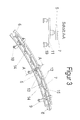
- the guide rail 4 is made of individual rail segments 5 accordingly FIG. 3 composed by each of the rail segments 5 at its end respectively has a positive and a negative-shaped segment connector 6, with which it is gap-free, positive and non-positively connected to its neighboring segments.
- the rail segment has 5 knob-shaped protuberances at its one butt end, which engage in identically shaped cutouts at the opposite end.
- Each rail segment 5 consists of two rail tracks 12, which are connected to each other via sleepers 13 in such a way that the rail tracks 12 and the sleepers 13 monolithically consist of a sheet-cut part and cohesive joints form each other, so that the rail tracks 12, at Almost constant gauge, easily screwed against each other.
- a rack 7 is mounted, wherein the division of the guide rail 4 in rail segments 5 is carried out so that the racks 7 of two adjacent segments join each other gap-free.
- each rail segment 5 has at least three rail feet 9.
- Each rail foot 9 in turn consists of at least two holding elements 10 which act, for example, magnetically or according to the principle of adhesive suction, and their base is negligible small to the radius of curvature of the larger or smaller element of the tubular node 2, 3.
- These holding elements 10 are connected by a ball joint to a connecting bridge 11, which in turn is ball-jointed with the rail segment 5 in the neutral fiber.
- each rail segment 5 has a segment coding 14 fixedly connected to it, which enables unambiguous identification of the segment.
- the coding can, as in FIG. 3 shown to be a binary coding similar to a punched card, a bar code or the like.
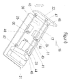
- the guide machine 16 accordingly FIG. 4 be placed by the mounted on a first bogie 18 and a second bogie 19 track rollers 20 with the guide rail 4 and the projecting from the cuboid machine body 17 pinion 21 are brought into engagement with the rack 7.
- a pressure device 30 the engagement of the track rollers 20 is made free of play with the guide rail 4.
- the over-heavy pipe knot 1 can not be moved to a preferred position for machining, which is why the guide machine 16 must be designed so that it is able to work in ascending and overhead positions.
- the bogies 18, 19 are pivotally connected to the machine body 17.
- the closer to the flange 22 first bogie 18 is connected by two serially arranged rotary joints with the machine body 17 by a first axis of rotation extending perpendicular to the extension plane of the first bogie 18 and a second axis of rotation extends so that they to this and the Brutangente the rail tracks 12 is vertical.
- the second bogie 19 is pivotally connected to the machine body 17.
- the pinion 21 is driven by the first drive 23 connected to the machine body 17, which in turn is influenced by a machine computer 31 arranged likewise in the machine body 17 in the sense of a numerically controlled movement axis.
- a fall protection 38 is attached on the machine body 17. This engages in the mounted on the guide rail 4 rack 7 and prevents that when machining in rising position by whatever type of defects, the guide machine 16 on the guide rail 4 can move in the direction of gravity without brakes. At the same time, however, the fall protection device 38 has a dead movement range, which allows unimpeded reversing movements of the guide machine 16 along the guide rail 4 to a certain extent.
- an encoding sensor 27 Attached to the side of the machine body 17 facing the guide rail 4 is an encoding sensor 27, which has the task of reading the segment coding 14 present on the individual rail segments 5 and transmitting them to the machine computer 31.
- the machine computer 31 decodes the signal and inserts it into the data stream intended for a system computer 32 without delay.
- the transmission of the data stream not online, so the immediate transmission of data from the machine computer 31 to the system computer 32 must be made, as well as is not required that there is a constant communication link between the machine computer 31 and the system computer 32.
- the machine computer 31 provides the data stream with a time stamp.
- FIG. 5 the controlled sliding movement of the flange 22 in a plane perpendicular to the direction of movement realized by the first drive 23.
- the second drive 24 between the machine body 17 and a parallel crank gear 26 is arranged, the frame side is also attached to the machine body 17.
- a coupling 33 there is the third drive 25 and a perpendicular to the plane of movement of the parallel crank gear 26 extending linear guide 34, which are both connected to the flange 22 and move it along the axis of the linear guide 34 linear. All three drives 23, 24 and 25 are integrated and protected in the cuboid machine body 17.
- the second drive 24 and the third drive 25 are, in an identical manner as the first drive 23, influenced by the machine computer 31 in terms of numerically controlled axes of motion, so that the flange 22 of the guide machine 16 is able to perform any programmed path movements relative to the guide rail 4 ,
- the programmed path motion can be corrected manually with offset values and adapted to the real geometric conditions by sending correction values to the machine computer 31 via a manual remote control device 35, which associates this with the stored path motion and drives the drives 23, 24 and 25 accordingly.
- a constructive variant for the movement of the flange 22 shows FIG. 6 , Arranged between the flange 22 and the machine body 17 are three coupling rods of the same length, a first coupling rod 39, a second coupling rod 40 and a third coupling rod 41.
- One of the coupling rods is equipped with two universal joints, a first universal joint 42 and a second universal joint 43 , the other two coupling rods with ball joints 44, 45, 46, 47.
- the flange 22 is slidable in two axes to the machine body 17.
- the two drives 24 and 25 are fixed to the machine body 17 connected and drive via angle lever 48, 49 and coupling rods 50, 51 the flange 22 at.
- the result is a non-linear transformation behavior of the movement of the drives 24, 25 for moving the flange 22, which must be computationally compensated by the machine computer 31.
- a low voltage is used, which is passed from a solid in the pipe node coordinate system power supply via a connector 36 into the machine body 17.
- the guiding machine 16 can also work independently by accordingly FIG. 7 the guide machine 16 a battery cart 37 is attached.
- the inventive solution is used to replace manual, physical and mental heavy activity while significantly increasing the efficiency of welding processing.
- Programmed parameters that can be reproduced at any time allow a reliable execution of the welding process in a consistent and very high quality.
- the equipment of the technical solution with distributed computer intelligence enables a great variety of welding technology processing and its adaptation to currently prevailing geometrical, material-technical and environmental conditions. At the same time, comprehensive documentation of the welding process is guaranteed.
Landscapes
- Engineering & Computer Science (AREA)
- Mechanical Engineering (AREA)
- Physics & Mathematics (AREA)
- Optics & Photonics (AREA)
- Plasma & Fusion (AREA)
- Butt Welding And Welding Of Specific Article (AREA)
Applications Claiming Priority (1)
| Application Number | Priority Date | Filing Date | Title |
|---|---|---|---|
| DE102010028593A DE102010028593B4 (de) | 2010-05-05 | 2010-05-05 | Einrichtung zur Herstellung von entlang räumlicher, in einer Ebene abwickelbarer Verschneidungskurven verlaufenden Schweißnähten für überschwere Rohrfachwerkverbindungen |
Publications (2)
| Publication Number | Publication Date |
|---|---|
| EP2384842A1 true EP2384842A1 (fr) | 2011-11-09 |
| EP2384842B1 EP2384842B1 (fr) | 2013-10-02 |
Family
ID=44512410
Family Applications (1)
| Application Number | Title | Priority Date | Filing Date |
|---|---|---|---|
| EP11162896.2A Not-in-force EP2384842B1 (fr) | 2010-05-05 | 2011-04-18 | Dispositif pour la réalisation de cordons de soudure s'étendant le long de courbes se découpant spatialement et pouvant se dérouler sur une surface pour connexion de charpente tubulaire hyperlourde |
Country Status (2)
| Country | Link |
|---|---|
| EP (1) | EP2384842B1 (fr) |
| DE (1) | DE102010028593B4 (fr) |
Cited By (7)
| Publication number | Priority date | Publication date | Assignee | Title |
|---|---|---|---|---|
| WO2013072016A1 (fr) * | 2011-11-16 | 2013-05-23 | WeserWind GmbH Offshore Construction Georgsmarienhütte | Procédé et dispositif de soudage et/ou de coupe de pièces, en particulier de tubes, pour la formation de structures offshore |
| WO2014200623A1 (fr) * | 2013-06-12 | 2014-12-18 | The Boeing Company | Systèmes et procédés de positionnement |
| CN104668849A (zh) * | 2015-03-13 | 2015-06-03 | 陈辉 | 管道相贯线划线、切割、焊接工具 |
| EP3338942A1 (fr) * | 2016-12-22 | 2018-06-27 | Airbus Operations S.A.S. | Dispositif de guidage adapte pour se positionner sur une surface a double rayon de courbure |
| CN112525928A (zh) * | 2020-10-19 | 2021-03-19 | 东方电气集团东方锅炉股份有限公司 | 焊缝射线检测胶片暗袋固定装置 |
| EP4139085A1 (fr) * | 2020-06-25 | 2023-03-01 | Siemens Energy Global GmbH & Co. KG | Machine-outil mobile et procédé d'usinage par segment d'un composant |
| CN119328270A (zh) * | 2024-11-05 | 2025-01-21 | 一重集团大连核电石化有限公司 | 一种泵壳双斜圆柱相贯面堆焊方法及装置 |
Families Citing this family (3)
| Publication number | Priority date | Publication date | Assignee | Title |
|---|---|---|---|---|
| AT522660A1 (de) | 2019-06-04 | 2020-12-15 | Smf Friedlbinder Gmbh | Verfahren und Vorrichtung zur automatischen Steuerung eines Metall-Schweißprozesses |
| US12502736B2 (en) | 2022-05-11 | 2025-12-23 | Caterpillar Inc. | Manual tube welding device |
| GB202305050D0 (en) * | 2023-04-05 | 2023-05-17 | Roger Nash Ltd | Improvements to welding apparatus and braking system therefore |
Citations (13)
| Publication number | Priority date | Publication date | Assignee | Title |
|---|---|---|---|---|
| JPS6012275A (ja) | 1983-03-18 | 1985-01-22 | Koike Sanso Kogyo Co Ltd | 曲線を追従しうる自動機又は溶接機 |
| DD224519A1 (de) | 1984-06-04 | 1985-07-10 | Zentralinstitut Schweiss | Einrichtung zur fuehrung eines schweissgeraetes |
| DD225078A1 (de) | 1984-07-02 | 1985-07-24 | Koethen Foerderanlagen Kranbau | Schweisstraktor |
| JPS6120700A (ja) | 1984-07-06 | 1986-01-29 | Nippon Kokan Kk <Nkk> | 自動溶接装置 |
| FR2610558A1 (fr) | 1987-02-06 | 1988-08-12 | Applic Tech Indles Moderne | Rail flexible de guidage de chariot porte-torche de soudage |
| US4841123A (en) * | 1987-06-17 | 1989-06-20 | Welding Services, Inc. | Automatic welding device |
| US5070792A (en) | 1990-04-09 | 1991-12-10 | Gullco International Limited | Multi-position travelling carriage with flexible track |
| JPH0578386U (ja) * | 1992-04-03 | 1993-10-26 | 株式会社神戸製鋼所 | レール走行台車 |
| JPH09234591A (ja) * | 1996-02-29 | 1997-09-09 | Mitsubishi Heavy Ind Ltd | 分解組立式自動溶接装置 |
| EP0759337B1 (fr) | 1995-08-17 | 1999-10-20 | Koike Sanso Kogyo Co., Ltd | Chariot avec une torche pour le coupage ou le soudage |
| US20040084545A1 (en) * | 2002-11-01 | 2004-05-06 | Pyrce Philip R. | Toy track and method of assembling and disassembling the same |
| JP2004141884A (ja) | 2002-10-22 | 2004-05-20 | Matsumoto Kikai Kk | 作業用走行台車 |
| JP2008200680A (ja) | 2007-02-16 | 2008-09-04 | Nippon Steel & Sumikin Welding Co Ltd | レール倣い台車および溶接装置 |
-
2010
- 2010-05-05 DE DE102010028593A patent/DE102010028593B4/de not_active Expired - Fee Related
-
2011
- 2011-04-18 EP EP11162896.2A patent/EP2384842B1/fr not_active Not-in-force
Patent Citations (13)
| Publication number | Priority date | Publication date | Assignee | Title |
|---|---|---|---|---|
| JPS6012275A (ja) | 1983-03-18 | 1985-01-22 | Koike Sanso Kogyo Co Ltd | 曲線を追従しうる自動機又は溶接機 |
| DD224519A1 (de) | 1984-06-04 | 1985-07-10 | Zentralinstitut Schweiss | Einrichtung zur fuehrung eines schweissgeraetes |
| DD225078A1 (de) | 1984-07-02 | 1985-07-24 | Koethen Foerderanlagen Kranbau | Schweisstraktor |
| JPS6120700A (ja) | 1984-07-06 | 1986-01-29 | Nippon Kokan Kk <Nkk> | 自動溶接装置 |
| FR2610558A1 (fr) | 1987-02-06 | 1988-08-12 | Applic Tech Indles Moderne | Rail flexible de guidage de chariot porte-torche de soudage |
| US4841123A (en) * | 1987-06-17 | 1989-06-20 | Welding Services, Inc. | Automatic welding device |
| US5070792A (en) | 1990-04-09 | 1991-12-10 | Gullco International Limited | Multi-position travelling carriage with flexible track |
| JPH0578386U (ja) * | 1992-04-03 | 1993-10-26 | 株式会社神戸製鋼所 | レール走行台車 |
| EP0759337B1 (fr) | 1995-08-17 | 1999-10-20 | Koike Sanso Kogyo Co., Ltd | Chariot avec une torche pour le coupage ou le soudage |
| JPH09234591A (ja) * | 1996-02-29 | 1997-09-09 | Mitsubishi Heavy Ind Ltd | 分解組立式自動溶接装置 |
| JP2004141884A (ja) | 2002-10-22 | 2004-05-20 | Matsumoto Kikai Kk | 作業用走行台車 |
| US20040084545A1 (en) * | 2002-11-01 | 2004-05-06 | Pyrce Philip R. | Toy track and method of assembling and disassembling the same |
| JP2008200680A (ja) | 2007-02-16 | 2008-09-04 | Nippon Steel & Sumikin Welding Co Ltd | レール倣い台車および溶接装置 |
Non-Patent Citations (2)
| Title |
|---|
| SCHRAFT, R.D., WANNER, M.C., HERKOMMER, T.F.: ""Skywash"-Aircraft cleaning by robots", 25TH INTERNATIONAL SYMPOSIUM OF INDUSTRIAL ROBOTS, PROCEEDINGS, 25 April 1994 (1994-04-25), pages 273 - 280 |
| WANNER, M.C.: "Projektdarstellung HfH, Hochflexible Handhabungssysteme", vol. 153, February 1990, pages: 3 - 29 |
Cited By (14)
| Publication number | Priority date | Publication date | Assignee | Title |
|---|---|---|---|---|
| WO2013072016A1 (fr) * | 2011-11-16 | 2013-05-23 | WeserWind GmbH Offshore Construction Georgsmarienhütte | Procédé et dispositif de soudage et/ou de coupe de pièces, en particulier de tubes, pour la formation de structures offshore |
| WO2014200623A1 (fr) * | 2013-06-12 | 2014-12-18 | The Boeing Company | Systèmes et procédés de positionnement |
| US9489550B2 (en) | 2013-06-12 | 2016-11-08 | The Boeing Company | Positioning systems and methods |
| CN104668849A (zh) * | 2015-03-13 | 2015-06-03 | 陈辉 | 管道相贯线划线、切割、焊接工具 |
| CN108216681A (zh) * | 2016-12-22 | 2018-06-29 | 空中客车运营简化股份公司 | 被设计成定位在具有双曲率半径的表面上的引导装置 |
| FR3061054A1 (fr) * | 2016-12-22 | 2018-06-29 | Airbus Operations | Dispositif de guidage adapte pour se positionner sur une surface a double rayon de courbure |
| EP3338942A1 (fr) * | 2016-12-22 | 2018-06-27 | Airbus Operations S.A.S. | Dispositif de guidage adapte pour se positionner sur une surface a double rayon de courbure |
| US10500710B2 (en) | 2016-12-22 | 2019-12-10 | Airbus Operations S.A.S. | Guiding device designed to be positioned on a surface with a double radius of curvature |
| CN108216681B (zh) * | 2016-12-22 | 2022-11-01 | 空中客车运营简化股份公司 | 被设计成定位在具有双曲率半径的表面上的引导装置 |
| EP4139085A1 (fr) * | 2020-06-25 | 2023-03-01 | Siemens Energy Global GmbH & Co. KG | Machine-outil mobile et procédé d'usinage par segment d'un composant |
| US12503943B2 (en) | 2020-06-25 | 2025-12-23 | Siemens Energy Global GmbH & Co. KG | Mobile machine tool and method for segmentally machining a component |
| CN112525928A (zh) * | 2020-10-19 | 2021-03-19 | 东方电气集团东方锅炉股份有限公司 | 焊缝射线检测胶片暗袋固定装置 |
| CN112525928B (zh) * | 2020-10-19 | 2023-10-31 | 东方电气集团东方锅炉股份有限公司 | 焊缝射线检测胶片暗袋固定装置 |
| CN119328270A (zh) * | 2024-11-05 | 2025-01-21 | 一重集团大连核电石化有限公司 | 一种泵壳双斜圆柱相贯面堆焊方法及装置 |
Also Published As
| Publication number | Publication date |
|---|---|
| DE102010028593A1 (de) | 2011-11-10 |
| DE102010028593B4 (de) | 2011-12-15 |
| EP2384842B1 (fr) | 2013-10-02 |
Similar Documents
| Publication | Publication Date | Title |
|---|---|---|
| EP2384842B1 (fr) | Dispositif pour la réalisation de cordons de soudure s'étendant le long de courbes se découpant spatialement et pouvant se dérouler sur une surface pour connexion de charpente tubulaire hyperlourde | |
| DE3419683C2 (fr) | ||
| EP0752499B1 (fr) | Wagon pour le chargement des rails de voie ferrée | |
| DE69219429T2 (de) | Bodenflächenstrahlgerät | |
| EP2387487B1 (fr) | Système de robot pour poser une file de rails | |
| DE10336032A1 (de) | Vorrichtung zum Schneiden oder Schweißen von rohrförmigen Werkstücken od. dgl. | |
| DE2813920C2 (de) | Justierbares Gestell für eine Rohrschweißmaschine | |
| EP0950597B1 (fr) | Système de guidage avec un chariot guidé sur un rail | |
| WO2024055058A1 (fr) | Dispositif de traitement pour le traitement de surfaces internes de conduits | |
| DE102017215166B4 (de) | Robotersystem | |
| WO2002042026A1 (fr) | Dispositif de production d'evidements successifs a distance reguliere dans une piece a usiner longitudinale | |
| EP4298280A1 (fr) | Dispositif et procédé d'usinage de matériau de la pointe de ceur d'un agencement de points | |
| EP2902297B1 (fr) | Dispositif de transport | |
| DE3139734C2 (fr) | ||
| EP0857524A2 (fr) | Dispositif pour former bobines de fil | |
| DE2151114C3 (de) | Fahrzeug zum Überprüfen von Rohrleitungen | |
| DE102014102603A1 (de) | Modulare, schienengeführte Bearbeitungsvorrichtung | |
| DE102016103526A1 (de) | Selbstfahrende Bearbeitungsvorrichtung | |
| DE3153391C2 (en) | Remote-control grinding apparatus | |
| DE2317554C3 (de) | Vorrichtung zum Entfernen von überstehenden Graten, SchweiBraupen oder dergleichen | |
| DE3224010A1 (de) | Zugmaschine fuer auf einem gleis verfahrbare grubenfahrzeuge des untertagebergbaues | |
| DE69712330T2 (de) | Vorrichtung zum Unterhalt und zur Reparatur von Eisenbahngleisen | |
| DE4433405A1 (de) | Vorrichtung zum automatischen Befahren von Rohren | |
| DE696331C (de) | Selbsttaetige Lichtbogenschweissvorrichtung, bei welcher der Schweisswagen auf Schienen ueber eine an beiden Enden gelagerte Bruecke faehrt | |
| DE8502277U1 (de) | Schweißvorrichtung für ein zylindrisches Rohr |
Legal Events
| Date | Code | Title | Description |
|---|---|---|---|
| 17P | Request for examination filed |
Effective date: 20110516 |
|
| AK | Designated contracting states |
Kind code of ref document: A1 Designated state(s): AL AT BE BG CH CY CZ DE DK EE ES FI FR GB GR HR HU IE IS IT LI LT LU LV MC MK MT NL NO PL PT RO RS SE SI SK SM TR |
|
| AX | Request for extension of the european patent |
Extension state: BA ME |
|
| PUAI | Public reference made under article 153(3) epc to a published international application that has entered the european phase |
Free format text: ORIGINAL CODE: 0009012 |
|
| GRAP | Despatch of communication of intention to grant a patent |
Free format text: ORIGINAL CODE: EPIDOSNIGR1 |
|
| RIC1 | Information provided on ipc code assigned before grant |
Ipc: B23K 9/032 20060101ALI20130426BHEP Ipc: H01M 8/02 20060101ALI20130426BHEP Ipc: C04B 37/00 20060101ALI20130426BHEP Ipc: B23K 37/02 20060101ALI20130426BHEP Ipc: B61B 13/02 20060101ALI20130426BHEP Ipc: B23Q 9/00 20060101ALI20130426BHEP Ipc: B23K 26/20 20060101ALI20130426BHEP Ipc: B23K 1/00 20060101AFI20130426BHEP Ipc: B23K 1/005 20060101ALI20130426BHEP Ipc: B23K 26/22 20060101ALI20130426BHEP Ipc: B23K 31/02 20060101ALI20130426BHEP Ipc: B23K 26/24 20060101ALI20130426BHEP |
|
| INTG | Intention to grant announced |
Effective date: 20130515 |
|
| GRAS | Grant fee paid |
Free format text: ORIGINAL CODE: EPIDOSNIGR3 |
|
| GRAA | (expected) grant |
Free format text: ORIGINAL CODE: 0009210 |
|
| AK | Designated contracting states |
Kind code of ref document: B1 Designated state(s): AL AT BE BG CH CY CZ DE DK EE ES FI FR GB GR HR HU IE IS IT LI LT LU LV MC MK MT NL NO PL PT RO RS SE SI SK SM TR |
|
| REG | Reference to a national code |
Ref country code: GB Ref legal event code: FG4D Free format text: NOT ENGLISH |
|
| REG | Reference to a national code |
Ref country code: CH Ref legal event code: EP Ref country code: AT Ref legal event code: REF Ref document number: 634342 Country of ref document: AT Kind code of ref document: T Effective date: 20131015 |
|
| REG | Reference to a national code |
Ref country code: IE Ref legal event code: FG4D Free format text: LANGUAGE OF EP DOCUMENT: GERMAN |
|
| REG | Reference to a national code |
Ref country code: DE Ref legal event code: R096 Ref document number: 502011001416 Country of ref document: DE Effective date: 20131128 |
|
| REG | Reference to a national code |
Ref country code: NL Ref legal event code: VDEP Effective date: 20131002 |
|
| PG25 | Lapsed in a contracting state [announced via postgrant information from national office to epo] |
Ref country code: SI Free format text: LAPSE BECAUSE OF FAILURE TO SUBMIT A TRANSLATION OF THE DESCRIPTION OR TO PAY THE FEE WITHIN THE PRESCRIBED TIME-LIMIT Effective date: 20131002 |
|
| REG | Reference to a national code |
Ref country code: LT Ref legal event code: MG4D |
|
| PG25 | Lapsed in a contracting state [announced via postgrant information from national office to epo] |
Ref country code: HR Free format text: LAPSE BECAUSE OF FAILURE TO SUBMIT A TRANSLATION OF THE DESCRIPTION OR TO PAY THE FEE WITHIN THE PRESCRIBED TIME-LIMIT Effective date: 20131002 Ref country code: NO Free format text: LAPSE BECAUSE OF FAILURE TO SUBMIT A TRANSLATION OF THE DESCRIPTION OR TO PAY THE FEE WITHIN THE PRESCRIBED TIME-LIMIT Effective date: 20140102 Ref country code: FI Free format text: LAPSE BECAUSE OF FAILURE TO SUBMIT A TRANSLATION OF THE DESCRIPTION OR TO PAY THE FEE WITHIN THE PRESCRIBED TIME-LIMIT Effective date: 20131002 Ref country code: SE Free format text: LAPSE BECAUSE OF FAILURE TO SUBMIT A TRANSLATION OF THE DESCRIPTION OR TO PAY THE FEE WITHIN THE PRESCRIBED TIME-LIMIT Effective date: 20131002 Ref country code: LT Free format text: LAPSE BECAUSE OF FAILURE TO SUBMIT A TRANSLATION OF THE DESCRIPTION OR TO PAY THE FEE WITHIN THE PRESCRIBED TIME-LIMIT Effective date: 20131002 Ref country code: IS Free format text: LAPSE BECAUSE OF FAILURE TO SUBMIT A TRANSLATION OF THE DESCRIPTION OR TO PAY THE FEE WITHIN THE PRESCRIBED TIME-LIMIT Effective date: 20140202 Ref country code: CZ Free format text: LAPSE BECAUSE OF FAILURE TO SUBMIT A TRANSLATION OF THE DESCRIPTION OR TO PAY THE FEE WITHIN THE PRESCRIBED TIME-LIMIT Effective date: 20131002 Ref country code: NL Free format text: LAPSE BECAUSE OF FAILURE TO SUBMIT A TRANSLATION OF THE DESCRIPTION OR TO PAY THE FEE WITHIN THE PRESCRIBED TIME-LIMIT Effective date: 20131002 |
|
| PG25 | Lapsed in a contracting state [announced via postgrant information from national office to epo] |
Ref country code: ES Free format text: LAPSE BECAUSE OF FAILURE TO SUBMIT A TRANSLATION OF THE DESCRIPTION OR TO PAY THE FEE WITHIN THE PRESCRIBED TIME-LIMIT Effective date: 20131002 Ref country code: PL Free format text: LAPSE BECAUSE OF FAILURE TO SUBMIT A TRANSLATION OF THE DESCRIPTION OR TO PAY THE FEE WITHIN THE PRESCRIBED TIME-LIMIT Effective date: 20131002 Ref country code: RS Free format text: LAPSE BECAUSE OF FAILURE TO SUBMIT A TRANSLATION OF THE DESCRIPTION OR TO PAY THE FEE WITHIN THE PRESCRIBED TIME-LIMIT Effective date: 20131002 Ref country code: LV Free format text: LAPSE BECAUSE OF FAILURE TO SUBMIT A TRANSLATION OF THE DESCRIPTION OR TO PAY THE FEE WITHIN THE PRESCRIBED TIME-LIMIT Effective date: 20131002 Ref country code: CY Free format text: LAPSE BECAUSE OF FAILURE TO SUBMIT A TRANSLATION OF THE DESCRIPTION OR TO PAY THE FEE WITHIN THE PRESCRIBED TIME-LIMIT Effective date: 20131002 |
|
| PG25 | Lapsed in a contracting state [announced via postgrant information from national office to epo] |
Ref country code: PT Free format text: LAPSE BECAUSE OF FAILURE TO SUBMIT A TRANSLATION OF THE DESCRIPTION OR TO PAY THE FEE WITHIN THE PRESCRIBED TIME-LIMIT Effective date: 20140203 |
|
| REG | Reference to a national code |
Ref country code: DE Ref legal event code: R097 Ref document number: 502011001416 Country of ref document: DE |
|
| PG25 | Lapsed in a contracting state [announced via postgrant information from national office to epo] |
Ref country code: EE Free format text: LAPSE BECAUSE OF FAILURE TO SUBMIT A TRANSLATION OF THE DESCRIPTION OR TO PAY THE FEE WITHIN THE PRESCRIBED TIME-LIMIT Effective date: 20131002 |
|
| PLBE | No opposition filed within time limit |
Free format text: ORIGINAL CODE: 0009261 |
|
| STAA | Information on the status of an ep patent application or granted ep patent |
Free format text: STATUS: NO OPPOSITION FILED WITHIN TIME LIMIT |
|
| PG25 | Lapsed in a contracting state [announced via postgrant information from national office to epo] |
Ref country code: RO Free format text: LAPSE BECAUSE OF FAILURE TO SUBMIT A TRANSLATION OF THE DESCRIPTION OR TO PAY THE FEE WITHIN THE PRESCRIBED TIME-LIMIT Effective date: 20131002 Ref country code: SK Free format text: LAPSE BECAUSE OF FAILURE TO SUBMIT A TRANSLATION OF THE DESCRIPTION OR TO PAY THE FEE WITHIN THE PRESCRIBED TIME-LIMIT Effective date: 20131002 Ref country code: IT Free format text: LAPSE BECAUSE OF FAILURE TO SUBMIT A TRANSLATION OF THE DESCRIPTION OR TO PAY THE FEE WITHIN THE PRESCRIBED TIME-LIMIT Effective date: 20131002 |
|
| 26N | No opposition filed |
Effective date: 20140703 |
|
| PG25 | Lapsed in a contracting state [announced via postgrant information from national office to epo] |
Ref country code: DK Free format text: LAPSE BECAUSE OF FAILURE TO SUBMIT A TRANSLATION OF THE DESCRIPTION OR TO PAY THE FEE WITHIN THE PRESCRIBED TIME-LIMIT Effective date: 20131002 |
|
| REG | Reference to a national code |
Ref country code: DE Ref legal event code: R097 Ref document number: 502011001416 Country of ref document: DE Effective date: 20140703 |
|
| PG25 | Lapsed in a contracting state [announced via postgrant information from national office to epo] |
Ref country code: MC Free format text: LAPSE BECAUSE OF FAILURE TO SUBMIT A TRANSLATION OF THE DESCRIPTION OR TO PAY THE FEE WITHIN THE PRESCRIBED TIME-LIMIT Effective date: 20131002 Ref country code: LU Free format text: LAPSE BECAUSE OF FAILURE TO SUBMIT A TRANSLATION OF THE DESCRIPTION OR TO PAY THE FEE WITHIN THE PRESCRIBED TIME-LIMIT Effective date: 20140418 |
|
| REG | Reference to a national code |
Ref country code: CH Ref legal event code: PL |
|
| REG | Reference to a national code |
Ref country code: FR Ref legal event code: ST Effective date: 20141231 |
|
| REG | Reference to a national code |
Ref country code: IE Ref legal event code: MM4A |
|
| PG25 | Lapsed in a contracting state [announced via postgrant information from national office to epo] |
Ref country code: CH Free format text: LAPSE BECAUSE OF NON-PAYMENT OF DUE FEES Effective date: 20140430 Ref country code: LI Free format text: LAPSE BECAUSE OF NON-PAYMENT OF DUE FEES Effective date: 20140430 |
|
| PG25 | Lapsed in a contracting state [announced via postgrant information from national office to epo] |
Ref country code: FR Free format text: LAPSE BECAUSE OF NON-PAYMENT OF DUE FEES Effective date: 20140430 |
|
| PG25 | Lapsed in a contracting state [announced via postgrant information from national office to epo] |
Ref country code: IE Free format text: LAPSE BECAUSE OF NON-PAYMENT OF DUE FEES Effective date: 20140418 |
|
| PG25 | Lapsed in a contracting state [announced via postgrant information from national office to epo] |
Ref country code: MT Free format text: LAPSE BECAUSE OF FAILURE TO SUBMIT A TRANSLATION OF THE DESCRIPTION OR TO PAY THE FEE WITHIN THE PRESCRIBED TIME-LIMIT Effective date: 20131002 |
|
| PG25 | Lapsed in a contracting state [announced via postgrant information from national office to epo] |
Ref country code: SM Free format text: LAPSE BECAUSE OF FAILURE TO SUBMIT A TRANSLATION OF THE DESCRIPTION OR TO PAY THE FEE WITHIN THE PRESCRIBED TIME-LIMIT Effective date: 20131002 Ref country code: NO Free format text: LAPSE BECAUSE OF FAILURE TO SUBMIT A TRANSLATION OF THE DESCRIPTION OR TO PAY THE FEE WITHIN THE PRESCRIBED TIME-LIMIT Effective date: 20140101 |
|
| PG25 | Lapsed in a contracting state [announced via postgrant information from national office to epo] |
Ref country code: BG Free format text: LAPSE BECAUSE OF FAILURE TO SUBMIT A TRANSLATION OF THE DESCRIPTION OR TO PAY THE FEE WITHIN THE PRESCRIBED TIME-LIMIT Effective date: 20131002 Ref country code: GR Free format text: LAPSE BECAUSE OF FAILURE TO SUBMIT A TRANSLATION OF THE DESCRIPTION OR TO PAY THE FEE WITHIN THE PRESCRIBED TIME-LIMIT Effective date: 20131002 |
|
| PG25 | Lapsed in a contracting state [announced via postgrant information from national office to epo] |
Ref country code: BE Free format text: LAPSE BECAUSE OF FAILURE TO SUBMIT A TRANSLATION OF THE DESCRIPTION OR TO PAY THE FEE WITHIN THE PRESCRIBED TIME-LIMIT Effective date: 20140430 Ref country code: HU Free format text: LAPSE BECAUSE OF FAILURE TO SUBMIT A TRANSLATION OF THE DESCRIPTION OR TO PAY THE FEE WITHIN THE PRESCRIBED TIME-LIMIT; INVALID AB INITIO Effective date: 20110418 Ref country code: TR Free format text: LAPSE BECAUSE OF FAILURE TO SUBMIT A TRANSLATION OF THE DESCRIPTION OR TO PAY THE FEE WITHIN THE PRESCRIBED TIME-LIMIT Effective date: 20131002 |
|
| REG | Reference to a national code |
Ref country code: AT Ref legal event code: MM01 Ref document number: 634342 Country of ref document: AT Kind code of ref document: T Effective date: 20160418 |
|
| PGFP | Annual fee paid to national office [announced via postgrant information from national office to epo] |
Ref country code: GB Payment date: 20170427 Year of fee payment: 7 |
|
| PG25 | Lapsed in a contracting state [announced via postgrant information from national office to epo] |
Ref country code: AT Free format text: LAPSE BECAUSE OF NON-PAYMENT OF DUE FEES Effective date: 20160418 |
|
| PG25 | Lapsed in a contracting state [announced via postgrant information from national office to epo] |
Ref country code: MK Free format text: LAPSE BECAUSE OF FAILURE TO SUBMIT A TRANSLATION OF THE DESCRIPTION OR TO PAY THE FEE WITHIN THE PRESCRIBED TIME-LIMIT Effective date: 20131002 |
|
| PG25 | Lapsed in a contracting state [announced via postgrant information from national office to epo] |
Ref country code: AL Free format text: LAPSE BECAUSE OF FAILURE TO SUBMIT A TRANSLATION OF THE DESCRIPTION OR TO PAY THE FEE WITHIN THE PRESCRIBED TIME-LIMIT Effective date: 20131002 |
|
| GBPC | Gb: european patent ceased through non-payment of renewal fee |
Effective date: 20180418 |
|
| PG25 | Lapsed in a contracting state [announced via postgrant information from national office to epo] |
Ref country code: GB Free format text: LAPSE BECAUSE OF NON-PAYMENT OF DUE FEES Effective date: 20180418 |
|
| PGFP | Annual fee paid to national office [announced via postgrant information from national office to epo] |
Ref country code: DE Payment date: 20190527 Year of fee payment: 9 |
|
| REG | Reference to a national code |
Ref country code: DE Ref legal event code: R119 Ref document number: 502011001416 Country of ref document: DE |
|
| PG25 | Lapsed in a contracting state [announced via postgrant information from national office to epo] |
Ref country code: DE Free format text: LAPSE BECAUSE OF NON-PAYMENT OF DUE FEES Effective date: 20201103 |